EP3410085B1 - Micromirror spectrophotometer assembly - Google Patents
Micromirror spectrophotometer assembly Download PDFInfo
- Publication number
- EP3410085B1 EP3410085B1 EP18175163.7A EP18175163A EP3410085B1 EP 3410085 B1 EP3410085 B1 EP 3410085B1 EP 18175163 A EP18175163 A EP 18175163A EP 3410085 B1 EP3410085 B1 EP 3410085B1
- Authority
- EP
- European Patent Office
- Prior art keywords
- instrument
- assembly
- integral
- optical
- assembly mounts
- Prior art date
- Legal status (The legal status is an assumption and is not a legal conclusion. Google has not performed a legal analysis and makes no representation as to the accuracy of the status listed.)
- Active
Links
Images




Classifications
-
- G—PHYSICS
- G01—MEASURING; TESTING
- G01J—MEASUREMENT OF INTENSITY, VELOCITY, SPECTRAL CONTENT, POLARISATION, PHASE OR PULSE CHARACTERISTICS OF INFRARED, VISIBLE OR ULTRAVIOLET LIGHT; COLORIMETRY; RADIATION PYROMETRY
- G01J3/00—Spectrometry; Spectrophotometry; Monochromators; Measuring colours
- G01J3/02—Details
- G01J3/0205—Optical elements not provided otherwise, e.g. optical manifolds, diffusers, windows
- G01J3/021—Optical elements not provided otherwise, e.g. optical manifolds, diffusers, windows using plane or convex mirrors, parallel phase plates, or particular reflectors
-
- G—PHYSICS
- G01—MEASURING; TESTING
- G01J—MEASUREMENT OF INTENSITY, VELOCITY, SPECTRAL CONTENT, POLARISATION, PHASE OR PULSE CHARACTERISTICS OF INFRARED, VISIBLE OR ULTRAVIOLET LIGHT; COLORIMETRY; RADIATION PYROMETRY
- G01J3/00—Spectrometry; Spectrophotometry; Monochromators; Measuring colours
- G01J3/02—Details
- G01J3/0202—Mechanical elements; Supports for optical elements
-
- G—PHYSICS
- G01—MEASURING; TESTING
- G01J—MEASUREMENT OF INTENSITY, VELOCITY, SPECTRAL CONTENT, POLARISATION, PHASE OR PULSE CHARACTERISTICS OF INFRARED, VISIBLE OR ULTRAVIOLET LIGHT; COLORIMETRY; RADIATION PYROMETRY
- G01J3/00—Spectrometry; Spectrophotometry; Monochromators; Measuring colours
- G01J3/02—Details
- G01J3/0205—Optical elements not provided otherwise, e.g. optical manifolds, diffusers, windows
- G01J3/0229—Optical elements not provided otherwise, e.g. optical manifolds, diffusers, windows using masks, aperture plates, spatial light modulators or spatial filters, e.g. reflective filters
-
- G—PHYSICS
- G01—MEASURING; TESTING
- G01J—MEASUREMENT OF INTENSITY, VELOCITY, SPECTRAL CONTENT, POLARISATION, PHASE OR PULSE CHARACTERISTICS OF INFRARED, VISIBLE OR ULTRAVIOLET LIGHT; COLORIMETRY; RADIATION PYROMETRY
- G01J3/00—Spectrometry; Spectrophotometry; Monochromators; Measuring colours
- G01J3/02—Details
- G01J3/0262—Constructional arrangements for removing stray light
-
- G—PHYSICS
- G01—MEASURING; TESTING
- G01J—MEASUREMENT OF INTENSITY, VELOCITY, SPECTRAL CONTENT, POLARISATION, PHASE OR PULSE CHARACTERISTICS OF INFRARED, VISIBLE OR ULTRAVIOLET LIGHT; COLORIMETRY; RADIATION PYROMETRY
- G01J3/00—Spectrometry; Spectrophotometry; Monochromators; Measuring colours
- G01J3/02—Details
- G01J3/0291—Housings; Spectrometer accessories; Spatial arrangement of elements, e.g. folded path arrangements
-
- G—PHYSICS
- G01—MEASURING; TESTING
- G01J—MEASUREMENT OF INTENSITY, VELOCITY, SPECTRAL CONTENT, POLARISATION, PHASE OR PULSE CHARACTERISTICS OF INFRARED, VISIBLE OR ULTRAVIOLET LIGHT; COLORIMETRY; RADIATION PYROMETRY
- G01J3/00—Spectrometry; Spectrophotometry; Monochromators; Measuring colours
- G01J3/02—Details
- G01J3/0297—Constructional arrangements for removing other types of optical noise or for performing calibration
-
- G—PHYSICS
- G01—MEASURING; TESTING
- G01J—MEASUREMENT OF INTENSITY, VELOCITY, SPECTRAL CONTENT, POLARISATION, PHASE OR PULSE CHARACTERISTICS OF INFRARED, VISIBLE OR ULTRAVIOLET LIGHT; COLORIMETRY; RADIATION PYROMETRY
- G01J3/00—Spectrometry; Spectrophotometry; Monochromators; Measuring colours
- G01J3/12—Generating the spectrum; Monochromators
- G01J3/18—Generating the spectrum; Monochromators using diffraction elements, e.g. grating
-
- G—PHYSICS
- G01—MEASURING; TESTING
- G01J—MEASUREMENT OF INTENSITY, VELOCITY, SPECTRAL CONTENT, POLARISATION, PHASE OR PULSE CHARACTERISTICS OF INFRARED, VISIBLE OR ULTRAVIOLET LIGHT; COLORIMETRY; RADIATION PYROMETRY
- G01J3/00—Spectrometry; Spectrophotometry; Monochromators; Measuring colours
- G01J3/28—Investigating the spectrum
-
- G—PHYSICS
- G01—MEASURING; TESTING
- G01J—MEASUREMENT OF INTENSITY, VELOCITY, SPECTRAL CONTENT, POLARISATION, PHASE OR PULSE CHARACTERISTICS OF INFRARED, VISIBLE OR ULTRAVIOLET LIGHT; COLORIMETRY; RADIATION PYROMETRY
- G01J3/00—Spectrometry; Spectrophotometry; Monochromators; Measuring colours
- G01J3/28—Investigating the spectrum
- G01J2003/2866—Markers; Calibrating of scan
Definitions
- Spectrophotometers can be used to measure the intensity of light as a function of its wavelength over a spectral range of light (e.g., the spectral bandwidth of the spectrophotometer). For a spectrophotometer, important aspects of measurements include the absorption, transmittance, and reflectance of light by samples, for example, measured as a percentage or other gauge or metric. Spectrophotometers are often used to identify or determine the quality or quantity of solutions and solids based on the transmittance and reflectance characteristics of those samples.
- an instrument as defined in claim 1 is provided.
- At least one of the assembly mounts can include a first integral seat formed for a first optical component of a focusing optics assembly and a second integral seat for a second optical component of the focusing optics assembly.
- the first integral seat and the second integral seat can be separated by a predetermined spacing along an optical pathway that extends along the at least one of the plurality of assembly mounts.
- a first of the assembly mounts can be aligned along a first optical pathway in the instrument
- a second of the plurality of assembly mounts can be aligned along a second optical pathway parallel to the first optical pathway in the instrument
- a third of the plurality of assembly mounts can be aligned along a third optical pathway at an angle with respect to at least one of the first optical pathway and the second optical pathway in the instrument.
- the plurality of optical components can be aligned and secured in the first, second, and third of the plurality of assembly mounts, and an assembly mount cover can be secured over the first, second, and third of the plurality of assembly mounts.
- a forth of the assembly mounts can also be aligned at one end of the first optical pathway to secure a light source and an entrance optics assembly of the instrument.
- a fifth of the assembly mounts can be positioned about an intersection of the first optical pathway and the second optical pathway to secure the diffraction grating.
- a sixth of the plurality of assembly mounts can be positioned about an intersection of the second optical pathway and the third optical pathway to secure the DMD; and the sixth of the plurality of assembly mounts includes a number of baffles integral to the base platform.
- the instrument can also include a motor and a reference paddle mechanically coupled to a shaft of the motor.
- the reference paddle can include a reference material for calibration of the instrument, and the motor can be configured to rotate the reference paddle to cover a sample window of the instrument for calibration of the instrument.
- the motor can also include a shaft that extends through a sample platform of the instrument and a sample tray mechanically coupled to the shaft of the motor.
- the instrument can also include a motor having a shaft configured to rotate a sample placed on the sample tray for measurement.
- the first of the integral assembly mounts can be aligned along a first optical pathway in the instrument.
- the second of the integral assembly mounts can be aligned along a second optical pathway parallel to the first optical pathway in the instrument.
- DLP Digital Light Processing
- DMD Digital Micromirror Device
- the base platform or chassis assembly includes a number of optical assembly mounts.
- the base platform assembly facilitates the assembly of optics in a predetermined, pre-aligned spectrophotometer configuration for taking spectral measurements of various samples, including natural and synthetic food and agricultural products, among others.
- Features of the embodiments include a simple-to-use, pre-aligned optical and electronic base platform assembly, an automatic reference reflector, and a rotating sample tray.
- the embodiments can also rely upon spectral region measurement stitching, spectral and calibration transfer between instruments, and the alignment of spectra with specialized wavelength standards, photometric standards, and lineshape correction methods.
- an instrument in one example described below, includes a diffraction grating to disperse broadband light over a range of wavelengths, a detector, a digital micromirror device (DMD) configured to scan through and reflect at least a portion of the range of wavelengths toward the detector, and a base platform having a number of integrally formed assembly mounts.
- the assembly mounts are formed to align and secure the diffraction grating, the detector, the DMD, and other optical components of the instrument in a predetermined arrangement.
- the instrument can also include a reference paddle having a reference material for calibration of the instrument, and a rotatable sample tray to rotate a sample placed on the sample tray for measurement.
- FIG. 1 illustrates an example spectrophotometer 10 according to an embodiment described herein.
- FIG. 1 is provided as a representative example for discussion.
- the example shown in FIG. 1 is not necessarily drawn to scale, does not exhaustively illustrate every part, piece, or component of the spectrophotometer 10, and is not intended to be limiting of the embodiments.
- Other arrangements of similar, additional, or fewer components can be used to achieve any number of the advantages described herein.
- the spectrophotometer 10 includes an enclosure 20, a sample platform 30 positioned at a top side of the enclosure 20, a power supply module 40, a computer control module 50, a support chassis 60, and a DLP-DMD measurement unit 100 ("measurement unit 100").
- the measurement unit 100 is secured by the support chassis 60 within the enclosure 20.
- the enclosure 20 can be embodied as any suitable case or enclosure, formed from plastic, metal, rubber, other materials, and/or combinations thereof, for enclosing and securing the components of the spectrophotometer 10.
- the support chassis 60 within the enclosure 20 can be formed from plastic, metal, rubber, and other materials suitable for supporting and securing the measurement unit 100, the sample platform 30, and other components of the spectrophotometer 10, such as a monitor, keyboard, mouse, etc.
- Both the enclosure 20 and the support chassis 60 can be embodied as a number of parts and/or pieces secured together using any suitable means, such as mechanical interferences or joints, mechanical fasteners ( e.g., screws, rivets, pins, interlocks), adhesives, etc.
- the sample platform 30 includes a sample window 32 as shown in FIG. 1 .
- samples for measurement by the spectrophotometer 10 can be placed in a sample cup, for example, and placed over the sample window 32 for measurement by the measurement unit 100 of the spectrophotometer 10 and analysis by the computer control module 50.
- the power supply module 40 can be embodied as any suitable power supply (e.g., switch-mode, regulated, or other power supply) to provide power to the computer control module 50, the measurement unit 100, and other components of the spectrophotometer 10, such as stepper and/or servo motors, solenoids, relays, and fans, among other components.
- the power supply module 40 can convert power from line voltage to lower voltage direct current power suitable for components in the spectrophotometer 10.
- the computer control module 50 can be embodied as one or more circuits, processors, processing circuits, memory devices, or any combination thereof configured to control components in the spectrophotometer 10.
- the computer control module 50 can be configured to capture, store, and analyze data captured by a detector in the measurement unit 100, as described in further detail below.
- the computer control module 50 can also be configured to forward and/or display data to other computing or display device(s), receive control instructions or feedback through I/O interfaces (e.g., keyboards, keypads, touchpads, pointing devices) of the spectrophotometer 10, and store and process various types of data.
- I/O interfaces e.g., keyboards, keypads, touchpads, pointing devices
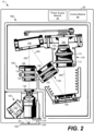
- FIG. 2 illustrates a representative block diagram of the example spectrophotometer 10 shown in FIG. 1 according to an embodiment described herein.
- a number of components of the measurement unit 100 are shown.
- a representative sample tray 102, sample tray drive motor 104, reference paddle 108, and reference paddle actuator 110 are shown.
- the reference paddle 108 is positioned within the enclosure 20, and the sample tray 102 is positioned outside the enclosure 20.
- the representative sample tray 102, sample tray drive motor 104, reference paddle 108, and reference paddle actuator 110 are described in further detail below with reference to FIGS. 6A and 6B .
- the measurement unit 100 includes a light source assembly 120, an optical focusing assembly 130, a diffraction grating 140, another optical focusing assembly 150, a digital micromirror device (DMD) 160, an optical collimating assembly 170, and a detector 180.
- the light source assembly 120 includes a light source 122 and an entrance optics assembly 124.
- the entrance optics assembly 124 is aligned with an entrance opening 126 in a cover of the measurement unit 100.
- light from the light source 122 can travel along an optical pathway 200 in the light source assembly 120, through the sample window 32, and illuminate a sample placed on, in, or over the sample tray 102.
- Light reflected (and not absorbed) off the sample can travel along an optical pathway 202, through the entrance optics assembly 124, and through the entrance opening 126 in the cover of the measurement unit 100.
- the cover of the measurement unit 100 is described in further detail below with reference to FIG. 5 .
- the light source 122 can include a halogen lamp or light bulb, although any source of broadband light suitable for the application can be relied upon among embodiments.
- the entrance optics assembly 124 can include optical elements that collimate light reflected off the sample, such as one or more spaced-apart expander and/or plano-convex lenses or other elements, without limitation.
- the entrance opening 126 can include a slit or other opening though which at least a portion of the light reflected off the sample can be passed through the cover of the measurement unit 100. In some cases, entrance opening 126 can be selectively covered and/or uncovered by a mechanical or electrical shutter (e.g., a liquid crystal, LCD, or similar device). The shutter can be actuated and controlled by the computer control module 50, for example, during various operations of the spectrophotometer 10, such as during dark scans, calibration or reference scans, and live scan operations, for example.
- a mechanical or electrical shutter e.g., a liquid crystal, LCD, or similar device
- the optical focusing assembly 130 can include one or more spaced-apart lenses, such as the lenses 132 and 134 and the optical filter 136 (e.g., optical bandwidth filter) shown in FIG. 2 .
- the lenses 132 and 134 and optical bandpass filter 136 can be secured in an optical assembly mount of a base platform of the measurement unit 100.
- the diffraction grating 140 can be embodied as a grating selected to disperse the light reflected off the sample into a range of wavelengths of light.
- the diffraction grating 140 can disperse light over the ultra-violet (UV) to visible (VIS) range of wavelengths.
- the diffraction grating 140 can disperse light over the near-infrared (NIR) to infrared (IR) range of wavelengths.
- NIR near-infrared
- the diffraction grating 140 can be selected to disperse light over any desired range of wavelengths.
- the diffraction grating 140 can be embodied as substrates of various sizes with parallel grooves replicated on their surfaces, as would be appreciated in the art.
- the diffraction grating 140 disperses the light reflected off the sample by spatially separating it according to wavelength.
- Various methods of manufacture of diffraction gratings are known in the field, and the diffraction grating 140 can be manufactured using any known method, such as by replication from master gratings, interferometric control, holographic generation, ion etching, or lithography, for example.
- the diffraction grating 140 can also include a coating of reflective material over the grooves, to reflect light.
- the diffraction grating 140 can be sourced from any manufacturer of diffraction gratings, such as Optometrics Corporation of Littleton, MA, Grating Works of Acton, MA, or Richardson Gratings TM of Rochester, NY, for example, among others.
- the optical focusing assembly 150 can include one or more spaced-apart lenses, such as the lenses 152 and 154 shown in FIG. 2 . As described in further detail below with reference to FIGS. 3 and 4 , the lenses 152 and 154 can be secured in an optical assembly mount of the base platform of the measurement unit 100.
- the DMD 160 can be embodied as an array of hundreds of thousands to millions of micromirrors.
- the micromirrors of the DMD 160 can be controlled, respectively, by the computer control module 50 (and/or additional electronic components) to scan through and reflect at least a portion of the dispersed wavelengths of light from the diffraction grating 140 along the optical pathway 206 toward the detector 180.
- the computer control module 50 and/or additional electronic components to scan through and reflect at least a portion of the dispersed wavelengths of light from the diffraction grating 140 along the optical pathway 206 toward the detector 180.
- the DMD 160 one or more wavelengths or ranges of wavelengths can be reflected toward the detector 180 for measurement over time.
- Individual wavelengths or ranges of wavelengths can be selected over time (e.g., scanned) by the computer control module 50 by selectively turning columns of micromirrors in the DMD 160 on or off, to reflect desired wavelengths to the detector 180.
- the DMD 160 allows for the use of a high-performance detector 180, while providing wavelength selection agility and speed in the spectrophotometer 10. Further, the DMD 160 allows for mechanical stability in the spectrophotometer 10 because it is not necessary to pivot or rotate the diffraction grating 140 as compared to conventional techniques.
- the optical collimating assembly 170 can include one or more spaced-apart lenses, such as the lenses 172, 174, and 176 shown in FIG. 2 . As described in further detail below with reference to FIGS. 3 and 4 , the lenses 172 and 174 can be secured in an optical assembly mount of the base platform of the measurement unit 100.
- the detector 180 is configured to measure the intensity of the light reflected off the sample (or the fraction of the light absorbed by the sample at specific wavelengths, i.e., the absorbance of the sample). The detector 180 further converts the light to one or more electrical signals for analysis by the computer control module 50.
- the electrical signals can be converted ( e.g., using one or more analog to digital converters) to data values from which a quantitative analysis of a variety of characteristics of the sample, including constituent analysis, moisture content, protein content, fat content, fiber content, amino acid content, taste, texture, viscosity, etc., can be determined.
- the detector 180 can include one or more charge-coupled device (CCD), indium gallium arsenide (InGaAs), or other ultraviolet through infrared image or light sensors that observe the reflection of light from the sample at one or more points of illumination.
- CCD charge-coupled device
- InGaAs indium gallium arsenide
- the field of view of the detector 180 can be restricted based on the relative geometry and/or placement of the lenses 172, 174, and 176 to maximize the collection of energy while minimizing the light inclusion of stray light.
- FIG. 3 illustrates a top-down view
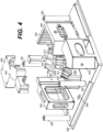
- FIG. 4 illustrates a perspective view of the base platform 300 of the measurement unit 100 in the example spectrophotometer 10 shown in FIG. 1 .
- the embodiment of the base platform 300 shown in FIGS. 3 and 4 is provided as a representative example. In other cases, the base platform 300 can include other arrangements (and numbers) of assembly mounts and seats within the assembly mounts.
- the base platform 300 includes a number of assembly mounts which are described in further detail below.
- a number of the assembly mounts are aligned along (and/or interfere with) one or more of the optical pathways 200, 202, 204, and 206.
- Some of the assembly mounts can be used to secure one or more lenses, optical filters, and/or other components in a predetermined, pre-aligned arrangement.
- Other assembly mounts can be used to secure one or more gratings, such as the diffraction grating 140, and electrical or optical-electrical components, such as the DMD 160 and the detector 180.
- the base platform 300 is formed as a single, integral unit.
- the base platform 300 is formed using an additive manufacturing process.
- Additive manufacturing processes include those processes by which three-dimensional (3D) objects can be formed by adding layer-upon-layer of the same material.
- Additive manufacturing processes include many technologies including 3D printing, rapid prototyping (RP), direct digital manufacturing (DDM), layered manufacturing, and additive fabrication.
- the process can be conducted using any suitable material, such as a plastic or polymer (e.g., acrylonitrile butadiene styrene (ABS), nylon, plastic resin, etc .) , poly-foam, Delrin ® , metal, etc.
- ABS acrylonitrile butadiene styrene
- Delrin ® poly-foam
- metal etc.
- the assembly mounts of the base platform 300 are formed to include a number of seats to secure one or more lenses, optical filters, and/or other components of the measurement unit 100 in a predetermined, pre-aligned arrangement.
- the measurement unit 100 of the spectrophotometer 10 can be assembled relatively quickly and easily in a repeatable fashion. Specifically, each of the lenses, optical filters, and/or other components of the measurement unit 100 can be inserted and secured into a corresponding seat in an assembly mount of the base platform 300.
- Each of the lenses, optical filters, and/or other components of the measurement unit 100 may take a different form, shape, and/or size.
- the seats for each of the components can, similarly, take a different form, shape, and/or size.
- each of the components will fit into one and only one seat (and possibly in only one orientation) in the base platform 300. In that case, the measurement unit 100 of the spectrophotometer 10 can be assembled in only one way.
- the base platform 300 includes the assembly mounts 320, 330, 340, 350, 360, and 370, for securing the light source assembly 120, the optical focusing assembly 130, the diffraction grating 140, the optical focusing assembly 150, the DMD 160, and the optical collimating assembly 170 and detector 180, respectively.
- the assembly mounts 320, 330, and 340 are spaced along the optical pathways 200 and 202.
- the assembly mounts 340, 350 and 360 are spaced along the optical pathway 204.
- the assembly mounts 360, 370, and 380 are spaced along the optical pathway 206.
- the light source 122 and the entrance optics assembly 124 can be secured within the assembly mount 320 by sliding them into openings within the assembly mount 320 and securing them in place using mechanical interferences or joints, mechanical fasteners (e.g., screws, rivets, pins, interlocks), adhesives, etc.
- the diffraction grating 140 can be secured within the assembly mount 340 by sliding it into the assembly mount 340 and securing it in place with any suitable means.
- the DMD 160 can also be secured within or to the assembly mount 360 by sliding it into the assembly mount 340 and securing it in place with any suitable means.
- the assembly mount 360 includes a number of baffles 362 and 364 to mitigate or block stray light within the measurement unit 100.
- the lenses 132 and 134 and the optical filter 136 of the optical focusing assembly 130 can be placed and secured into the seats 332, 334, and 336 of the assembly mount 320.
- the lenses 152 and 154 of the optical focusing assembly 150 can be placed and secured into the seats 352 and 354 of the assembly mount 350.
- the lenses 172, 174, and 176 of the optical collimating assembly 170 can also be placed and secured into the seats 372, 374, and 376 of the assembly mount 370.
- the detector 180 can be placed and secured into the seat 378 of the assembly mount 370.
- the components (e.g., lenses, filters, mirrors, gratings, detectors, etc .) of the measurement unit 100 can be secured into the seats of the base platform 300 by being placed within and, in some cases, held in place by mechanical contact, foam spacers, adhesives, or other means. Further, after various components have been seated into the seats 332, 334, 336, 352, 354, 372, 374, and 376 of the assembly mounts 330, 350, 360, and 370, the assembly mounts 330, 350, 360 and 370 can be closed using one or more assembly mount covers, such as the assembly mount cover 400 shown in FIG. 4 .
- the assembly mount cover 400 can include seats corresponding in size and position with the seats 332, 334, 336, 352, 354, 372, 374, and 376 of the assembly mounts 330, 350, and 370.
- One or more of the assembly mounts 330, 350, and 370 can include holes ( e.g., see reference 398 in FIG. 3 ), which can be threaded in some cases.
- the assembly mount cover 400 can also include holes, one of which is designated by reference 402 in FIG. 4 .
- the assembly mount cover 400 can be placed over the assembly mounts 330, 350, and 370.
- a mechanical fastener such as a screw, can be passed through the hole 402 of the assembly mount cover 400 and threaded into the hole 398 (see FIG. 3 ) of the assembly mount 350 for securing the assembly mount cover 400 over the assembly mounts 330, 350, and 370.
- each of the seats 332, 334, 336, 352, 354, 372, 374, and 376 is formed to have a predetermined size (e.g., length, width, height, radius of curvature, etc .) for a particular one of the components of the measurement unit 100.
- the placement of each of the components can be predetermined in a particular spaced-apart arrangement defined by the base platform 300 with respect to one or more of the optical pathways 200, 202, 204, and 206.
- the seats 372 and 374 are spaced apart by the distance "A" along the optical pathway 206
- the seats 374 and 376 are spaced apart by the distance "B" along the optical pathway 206.
- any of the seats shown in FIGS. 3 and 4 can be spaced-apart by other distances depending upon the types and arrangements of the components of the measurement unit 100.
- the measurement unit 100 can be assembled relatively quickly and easily as each of the lenses, optical filters, and other components of the measurement unit 100 can be inserted and secured into a corresponding assembly mount and/or seat of the base platform 300.
- each of the components will fit into one and only one assembly mount and/or seat (and possibly in only one orientation) in the base platform 300.
- the measurement unit 100 of the spectrophotometer 10 can be assembled in only one way. As compared to conventional techniques without the use of a base platform as described herein, it can be relatively time consuming and difficult to ensure that all the components of a spectrophotometer are aligned properly.
- the base platform 300 also includes number of standoffs 390-393 and eyelets 394 and 395 as shown in FIG. 3 .
- a cover can be mounted over the base platform 300, seated into and against the channel 396 along a length of the bottom edge of the base platform 300, and secured against the top ends of the standoffs 390-393 using screws or other mechanical fastening means.
- the measurement unit 100 can be secured to the support chassis 60 within the enclosure 20 of the spectrophotometer 10 as shown in FIG. 1 .
- the eyelets 394 and 395 can be used to pass wiring assemblies, harnesses, etc. between the components inside the measurement unit 100, the power supply module 40, and the computer control module 50.
- the base platform 300 illustrated in FIGS. 3 and 4 is provided as a representative example.
- Other base platforms for other instruments can include other numbers and arrangements of assembly mounts.
- other base platforms can include assembly mounts aligned along optical pathways other than those shown in FIGS 3 and 4 .
- assembly mounts can be formed at other positions in a base platform for alignment to other optical pathways at other angles with respect to each other in any suitable manner.
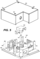
- FIG. 5 illustrates a perspective view of the base platform 300, assembly mount cover 400 of the base platform 300, and cover 500 of the measurement unit 100 in the example spectrophotometer 10 shown in FIG. 1 .
- the base platform 300 includes a number of standoffs 390-393.
- the cover 500 can be mounted over the base platform 300, seated into and against the channel 396 along a length of the bottom edge of the base platform 300, and secured against the top ends of the standoffs 390-393 using screws or other mechanical fastening means passed through holes 501-504 in the cover 500.
- the measurement unit 100 When the measurement unit 100 is fully assembled and the cover 500 of the base platform 300 is secured, the measurement unit 100 can be secured to the support chassis 60 within the enclosure 20 of the spectrophotometer 10.
- FIGS. 6A and 6B respectively, illustrate top and bottom views of a sample platform 30 of the example spectrophotometer 10 shown in FIG. 1 .
- the sample platform includes the sample window 32.
- Light from the light source assembly 120 can pass through the sample window 32 and exit the enclosure 20 of the spectrophotometer 10 along optical pathway 200 ( FIG. 2 ).
- optical pathway 200 FIG. 2
- light that passes through the sample window 32 can illuminate a sample placed on, in, or over the sample tray 102 above the sample window 32. Light reflected (and not absorbed) off the sample can travel back through the sample window 32 and into the measurement unit 100.
- a motor 600 is secured to the bottom side of the sample platform 30.
- a stepper or servo motor 630 is also secured to the bottom side of the sample platform 30.
- the computer control module 50 can also control the servo motor 630 to rotate a sample tray 102 placed over the sample window 32 in the sample platform 30.
- a reference paddle 610 is mechanically secured to a shaft of the motor 600. When assembled with the motor 600 to the sample platform 30, the reference paddle 610 occupies a recess 620 in the bottom of the sample platform 30.
- the computer control module 50 can control the motor 600 to rotate the reference paddle 610 between a first position 622 in the recess 620 and a second position 624 in the recess 620.
- the reference paddle 610 covers the sample window 32. As such, it interferes with the optical pathway 200 ( FIG. 2 ). In the first position 622, light from the light source assembly 120 falls upon and is reflected off of the reference paddle 610 rather than passing through the sample window 32.
- the reference paddle 610 includes a recessed area 612 for a reflective reference material.
- the recessed area 612 can be covered in gold plating reflective reference material for calibration of the spectrophotometer 10.
- the recessed plating area 612 can be covered or plated using other reference materials, such as polytetrafluoroethylene (PTFE), teflon, reflective metal(s), or a diffuse mirrored surface material, among others.
- FIG. 7 illustrates the sample tray 102 of the example spectrophotometer 10 shown in FIG. 1 .
- the sample tray 102 is mechanically coupled to a shaft of the stepper or servo motor 630 ( FIG. 6B ) through the sample platform 30, and the computer control module 50 can also control the servo motor 630 to rotate the sample tray 102.
- the sample tray 102 can be rotated at the direction of the computer control module 50.
- the sample tray 102 includes a sample cup adapter 700 mounted and secured thereto. As shown in FIG. 7 , the sample cup adapter 700 is mounted to the sample tray 102 above the sample window 32. When a sample for measurement is placed in or on the sample cup adapter 700, possibly in a sample cup or other fixture, it can be rotated. In other words, sample cup adapter 700 can be rotated along with the sample tray 102 using the stepper or servo motor 630. The sample cup adapter 700 can be rotated at different (or variable) speeds, for example, from a few degrees per second to about 180 degrees per second based on control provided by the computer control module 50.
- measurements can be taken in a more representative and/or comprehensive manner because light can be reflected (or absorbed) off the sample at different times or over time from different positions or orientations of the sample.
- one or more aspects of spectral region measurement stitching, spectral and calibration transfer between instruments, and the alignment of spectra with specialized wavelength standards, photometric standards, and lineshape correction methods can be incorporated into the spectrophotometer 10.
- FIG. 8 illustrates an example schematic block diagram of processing circuitry which can be employed as the computer control module 50 in the spectrophotometer 10 shown in FIG. 1 according to an embodiment described herein.
- the processing circuitry 800 can be embodied, in part, using one or more elements of a general purpose or specialized embedded computer.
- the processing circuitry 800 includes a processor 810, a Random Access Memory (RAM) 820, a Read Only Memory (ROM) 830, a memory device 840, and an Input Output (“I/O") interface 850.
- the elements of the processing circuitry 800 are communicatively coupled via a local interface 802.
- the elements of the processing circuitry 800 described herein are not intended to be limiting in nature, and the processing circuitry 800 can include other elements.
- the processor 810 can comprise any well-known general purpose arithmetic processor, programmable logic device, state machine, or Application Specific Integrated Circuit (ASIC), for example.
- the processor 810 can include one or more circuits, one or more microprocessors, ASICs, dedicated hardware, or any combination thereof.
- the processor 810 is configured to execute one or more software modules.
- the processor 810 can further include memory configured to store instructions and/or code to various functions, as further described herein.
- the processor 810 can comprise a general purpose, state machine, or ASIC processor, and various processes can be implemented or executed by the general purpose, state machine, or ASIC processor according software execution, by firmware, or a combination of a software execution and firmware.
- the RAM and ROM 820 and 830 can comprise any well-known random access and read only memory devices that store computer-readable instructions to be executed by the processor 810.
- the memory device 840 stores computer-readable instructions thereon that, when executed by the processor 810, direct the processor 810 to direct the spectrophotometer 10 to perform various aspects of the embodiments described herein.
- the memory device 840 can comprise one or more non-transitory devices or mediums including an optical disc, a magnetic disc, a semiconductor memory (i.e., a semiconductor, floating gate, or similar flash based memory), MLC Negative-AND-based flash memory, a magnetic tape memory, a removable memory, combinations thereof, or any other known memory means for storing computer-readable instructions.
- the I/O interface 850 can comprise device input and output interfaces such as keyboard, pointing device, display, communication, and/or other interfaces, such as a network interface, for example.
- the local interface 802 electrically and communicatively couples the processor 810, the RAM 820, the ROM 830, the memory device 840, and the I/O interface 850, so that data and instructions can be communicated among them.
- the processor 810 is configured to retrieve computer-readable instructions and data stored on the memory device 840, the RAM 820, the ROM 830, and/or other storage means, and copy the computer-readable instructions to the RAM 820 or the ROM 830 for execution, for example.
- the processor 810 is further configured to execute the computer-readable instructions to implement various aspects and features of the embodiments described herein.
Landscapes
- Physics & Mathematics (AREA)
- Spectroscopy & Molecular Physics (AREA)
- General Physics & Mathematics (AREA)
- Investigating Or Analysing Materials By Optical Means (AREA)
Applications Claiming Priority (1)
| Application Number | Priority Date | Filing Date | Title |
|---|---|---|---|
| US15/610,998 US10054483B1 (en) | 2017-06-01 | 2017-06-01 | Micromirror spectrophotometer assembly |
Publications (2)
| Publication Number | Publication Date |
|---|---|
| EP3410085A1 EP3410085A1 (en) | 2018-12-05 |
| EP3410085B1 true EP3410085B1 (en) | 2025-02-12 |
Family
ID=62492496
Family Applications (1)
| Application Number | Title | Priority Date | Filing Date |
|---|---|---|---|
| EP18175163.7A Active EP3410085B1 (en) | 2017-06-01 | 2018-05-30 | Micromirror spectrophotometer assembly |
Country Status (3)
| Country | Link |
|---|---|
| US (2) | US10054483B1 (da) |
| EP (1) | EP3410085B1 (da) |
| DK (1) | DK3410085T3 (da) |
Families Citing this family (5)
| Publication number | Priority date | Publication date | Assignee | Title |
|---|---|---|---|---|
| US10054483B1 (en) * | 2017-06-01 | 2018-08-21 | Westco Scientific Instruments, Inc | Micromirror spectrophotometer assembly |
| US20190021601A1 (en) * | 2017-07-19 | 2019-01-24 | Colgate-Palmolive Company | Compact Imaging System and Method Therefor |
| CN109883549B (zh) * | 2019-03-05 | 2021-03-12 | 吉林大学 | 一种基于数字微镜的弯曲谱线校正方法 |
| EP4047354B1 (en) * | 2019-11-08 | 2026-04-29 | HORIBA, Ltd. | Laser analysis device |
| USD1115568S1 (en) * | 2021-09-13 | 2026-03-03 | Byk Gardner Gmbh | Spectral photometer |
Citations (1)
| Publication number | Priority date | Publication date | Assignee | Title |
|---|---|---|---|---|
| WO2017079433A1 (en) * | 2015-11-03 | 2017-05-11 | Waters Technologies Corporation | Dmd based uv absorption detector for liquid chromatography |
Family Cites Families (5)
| Publication number | Priority date | Publication date | Assignee | Title |
|---|---|---|---|---|
| EP0296259A1 (en) * | 1987-06-22 | 1988-12-28 | Pacific Scientific Company | Spectrometer with combined visible and ultraviolet sample illumination |
| US6128078A (en) * | 1999-04-09 | 2000-10-03 | Three Lc, Inc. | Radiation filter, spectrometer and imager using a micro-mirror array |
| US7440098B2 (en) * | 2006-04-04 | 2008-10-21 | Custom Sensors And Technology | Spectroscope and method of performing spectroscopy utilizing a micro mirror array |
| US9404799B2 (en) | 2013-03-15 | 2016-08-02 | Westco Scientific Instruments, Inc. | Tandem dispersive range monochromator |
| US10054483B1 (en) * | 2017-06-01 | 2018-08-21 | Westco Scientific Instruments, Inc | Micromirror spectrophotometer assembly |
-
2017
- 2017-06-01 US US15/610,998 patent/US10054483B1/en active Active
-
2018
- 2018-05-30 EP EP18175163.7A patent/EP3410085B1/en active Active
- 2018-05-30 DK DK18175163.7T patent/DK3410085T3/da active
- 2018-07-13 US US16/035,061 patent/US10309829B2/en active Active
Patent Citations (1)
| Publication number | Priority date | Publication date | Assignee | Title |
|---|---|---|---|---|
| WO2017079433A1 (en) * | 2015-11-03 | 2017-05-11 | Waters Technologies Corporation | Dmd based uv absorption detector for liquid chromatography |
Also Published As
| Publication number | Publication date |
|---|---|
| EP3410085A1 (en) | 2018-12-05 |
| US20180348052A1 (en) | 2018-12-06 |
| US10054483B1 (en) | 2018-08-21 |
| US10309829B2 (en) | 2019-06-04 |
| DK3410085T3 (da) | 2025-04-22 |
Similar Documents
| Publication | Publication Date | Title |
|---|---|---|
| US10309829B2 (en) | Micromirror spectrophotometer assembly | |
| EP2831566B1 (en) | Optical analyzer for identification of materials using transmission spectroscopy | |
| KR101988697B1 (ko) | 휴대용 분광계 | |
| RU2457447C2 (ru) | Устройство и способ проверки образца волос | |
| AU2017343368B2 (en) | A spectrometer apparatus for measuring spectra of a liquid sample using an integrating cavity | |
| US9551612B2 (en) | Tandem dispersive range monochromator | |
| CN103620375B (zh) | 高通量准直照射器和均匀场照射的方法 | |
| US9546903B2 (en) | Data knitting tandem dispersive range monochromator | |
| US20250389644A1 (en) | Devices, Systems, and Methods for Analyzing Measurement Objects | |
| JP4192012B2 (ja) | 品質評価装置及び品質計測用設備 | |
| US8213011B2 (en) | Spatial imaging/imaging spectroscopy system and method | |
| TWI733911B (zh) | 光譜儀、計量工具及用於光譜取樣之方法 | |
| US10215635B2 (en) | Data blending multiple dispersive range monochromator | |
| Løvhaugen et al. | Dedicated spectrometers based on diffractive optics: design, modelling and evaluation | |
| Boateng et al. | Modular 3D-printed biophotonic platform for cost-effective hyperspectral and polarimetric imaging | |
| US10345228B2 (en) | Dark reference standard and measurement thereof | |
| JP2004219376A (ja) | 果菜類の品質評価装置 | |
| JP2002168772A (ja) | 分光分析装置 | |
| JP3402524B2 (ja) | 三次元分光測色器 | |
| Chia et al. | Investigating the Feasibility of a CMOS Camera in Developing a Shortwave Near Infrared Spectroscopy | |
| Chen et al. | Development of a hyperspectral imaging technique with internal scene scan for analysing the chemistry of food degradation | |
| JP4326426B2 (ja) | 分光分析装置の評価方法及び評価装置 | |
| NZ752100B2 (en) | A spectrometer apparatus for measuring spectra of a liquid sample using an integrating cavity | |
| FR2907552A1 (fr) | Systeme d'analyse spectrophotometrique a detecteur mobile |
Legal Events
| Date | Code | Title | Description |
|---|---|---|---|
| PUAI | Public reference made under article 153(3) epc to a published international application that has entered the european phase |
Free format text: ORIGINAL CODE: 0009012 |
|
| STAA | Information on the status of an ep patent application or granted ep patent |
Free format text: STATUS: THE APPLICATION HAS BEEN PUBLISHED |
|
| AK | Designated contracting states |
Kind code of ref document: A1 Designated state(s): AL AT BE BG CH CY CZ DE DK EE ES FI FR GB GR HR HU IE IS IT LI LT LU LV MC MK MT NL NO PL PT RO RS SE SI SK SM TR |
|
| AX | Request for extension of the european patent |
Extension state: BA ME |
|
| STAA | Information on the status of an ep patent application or granted ep patent |
Free format text: STATUS: REQUEST FOR EXAMINATION WAS MADE |
|
| 17P | Request for examination filed |
Effective date: 20190522 |
|
| RBV | Designated contracting states (corrected) |
Designated state(s): AL AT BE BG CH CY CZ DE DK EE ES FI FR GB GR HR HU IE IS IT LI LT LU LV MC MK MT NL NO PL PT RO RS SE SI SK SM TR |
|
| STAA | Information on the status of an ep patent application or granted ep patent |
Free format text: STATUS: EXAMINATION IS IN PROGRESS |
|
| 17Q | First examination report despatched |
Effective date: 20220506 |
|
| P01 | Opt-out of the competence of the unified patent court (upc) registered |
Effective date: 20230526 |
|
| GRAP | Despatch of communication of intention to grant a patent |
Free format text: ORIGINAL CODE: EPIDOSNIGR1 |
|
| STAA | Information on the status of an ep patent application or granted ep patent |
Free format text: STATUS: GRANT OF PATENT IS INTENDED |
|
| RIC1 | Information provided on ipc code assigned before grant |
Ipc: G01J 3/28 20060101ALN20240815BHEP Ipc: G01J 3/18 20060101ALI20240815BHEP Ipc: G01J 3/02 20060101AFI20240815BHEP |
|
| INTG | Intention to grant announced |
Effective date: 20240902 |
|
| RIC1 | Information provided on ipc code assigned before grant |
Ipc: G01J 3/28 20060101ALN20240823BHEP Ipc: G01J 3/18 20060101ALI20240823BHEP Ipc: G01J 3/02 20060101AFI20240823BHEP |
|
| GRAS | Grant fee paid |
Free format text: ORIGINAL CODE: EPIDOSNIGR3 |
|
| GRAA | (expected) grant |
Free format text: ORIGINAL CODE: 0009210 |
|
| STAA | Information on the status of an ep patent application or granted ep patent |
Free format text: STATUS: THE PATENT HAS BEEN GRANTED |
|
| AK | Designated contracting states |
Kind code of ref document: B1 Designated state(s): AL AT BE BG CH CY CZ DE DK EE ES FI FR GB GR HR HU IE IS IT LI LT LU LV MC MK MT NL NO PL PT RO RS SE SI SK SM TR |
|
| RAP1 | Party data changed (applicant data changed or rights of an application transferred) |
Owner name: KPM ANALYTICS NORTH AMERICA CORPORATION |
|
| REG | Reference to a national code |
Ref country code: GB Ref legal event code: FG4D |
|
| REG | Reference to a national code |
Ref country code: CH Ref legal event code: EP |
|
| REG | Reference to a national code |
Ref country code: DE Ref legal event code: R096 Ref document number: 602018079022 Country of ref document: DE |
|
| REG | Reference to a national code |
Ref country code: IE Ref legal event code: FG4D |
|
| REG | Reference to a national code |
Ref country code: NL Ref legal event code: FP |
|
| REG | Reference to a national code |
Ref country code: DK Ref legal event code: T3 Effective date: 20250414 |
|
| PG25 | Lapsed in a contracting state [announced via postgrant information from national office to epo] |
Ref country code: RS Free format text: LAPSE BECAUSE OF FAILURE TO SUBMIT A TRANSLATION OF THE DESCRIPTION OR TO PAY THE FEE WITHIN THE PRESCRIBED TIME-LIMIT Effective date: 20250512 |
|
| PG25 | Lapsed in a contracting state [announced via postgrant information from national office to epo] |
Ref country code: FI Free format text: LAPSE BECAUSE OF FAILURE TO SUBMIT A TRANSLATION OF THE DESCRIPTION OR TO PAY THE FEE WITHIN THE PRESCRIBED TIME-LIMIT Effective date: 20250212 |
|
| PG25 | Lapsed in a contracting state [announced via postgrant information from national office to epo] |
Ref country code: PL Free format text: LAPSE BECAUSE OF FAILURE TO SUBMIT A TRANSLATION OF THE DESCRIPTION OR TO PAY THE FEE WITHIN THE PRESCRIBED TIME-LIMIT Effective date: 20250212 |
|
| PG25 | Lapsed in a contracting state [announced via postgrant information from national office to epo] |
Ref country code: ES Free format text: LAPSE BECAUSE OF FAILURE TO SUBMIT A TRANSLATION OF THE DESCRIPTION OR TO PAY THE FEE WITHIN THE PRESCRIBED TIME-LIMIT Effective date: 20250212 |
|
| REG | Reference to a national code |
Ref country code: LT Ref legal event code: MG9D |
|
| PG25 | Lapsed in a contracting state [announced via postgrant information from national office to epo] |
Ref country code: IS Free format text: LAPSE BECAUSE OF FAILURE TO SUBMIT A TRANSLATION OF THE DESCRIPTION OR TO PAY THE FEE WITHIN THE PRESCRIBED TIME-LIMIT Effective date: 20250612 Ref country code: NO Free format text: LAPSE BECAUSE OF FAILURE TO SUBMIT A TRANSLATION OF THE DESCRIPTION OR TO PAY THE FEE WITHIN THE PRESCRIBED TIME-LIMIT Effective date: 20250512 |
|
| PG25 | Lapsed in a contracting state [announced via postgrant information from national office to epo] |
Ref country code: HR Free format text: LAPSE BECAUSE OF FAILURE TO SUBMIT A TRANSLATION OF THE DESCRIPTION OR TO PAY THE FEE WITHIN THE PRESCRIBED TIME-LIMIT Effective date: 20250212 |
|
| PG25 | Lapsed in a contracting state [announced via postgrant information from national office to epo] |
Ref country code: LV Free format text: LAPSE BECAUSE OF FAILURE TO SUBMIT A TRANSLATION OF THE DESCRIPTION OR TO PAY THE FEE WITHIN THE PRESCRIBED TIME-LIMIT Effective date: 20250212 Ref country code: PT Free format text: LAPSE BECAUSE OF FAILURE TO SUBMIT A TRANSLATION OF THE DESCRIPTION OR TO PAY THE FEE WITHIN THE PRESCRIBED TIME-LIMIT Effective date: 20250612 |
|
| PG25 | Lapsed in a contracting state [announced via postgrant information from national office to epo] |
Ref country code: BG Free format text: LAPSE BECAUSE OF FAILURE TO SUBMIT A TRANSLATION OF THE DESCRIPTION OR TO PAY THE FEE WITHIN THE PRESCRIBED TIME-LIMIT Effective date: 20250212 Ref country code: GR Free format text: LAPSE BECAUSE OF FAILURE TO SUBMIT A TRANSLATION OF THE DESCRIPTION OR TO PAY THE FEE WITHIN THE PRESCRIBED TIME-LIMIT Effective date: 20250513 |
|
| REG | Reference to a national code |
Ref country code: AT Ref legal event code: MK05 Ref document number: 1766418 Country of ref document: AT Kind code of ref document: T Effective date: 20250212 |
|
| PG25 | Lapsed in a contracting state [announced via postgrant information from national office to epo] |
Ref country code: SE Free format text: LAPSE BECAUSE OF FAILURE TO SUBMIT A TRANSLATION OF THE DESCRIPTION OR TO PAY THE FEE WITHIN THE PRESCRIBED TIME-LIMIT Effective date: 20250212 |
|
| PG25 | Lapsed in a contracting state [announced via postgrant information from national office to epo] |
Ref country code: SM Free format text: LAPSE BECAUSE OF FAILURE TO SUBMIT A TRANSLATION OF THE DESCRIPTION OR TO PAY THE FEE WITHIN THE PRESCRIBED TIME-LIMIT Effective date: 20250212 |
|
| PG25 | Lapsed in a contracting state [announced via postgrant information from national office to epo] |
Ref country code: IT Free format text: LAPSE BECAUSE OF FAILURE TO SUBMIT A TRANSLATION OF THE DESCRIPTION OR TO PAY THE FEE WITHIN THE PRESCRIBED TIME-LIMIT Effective date: 20250212 |
|
| PG25 | Lapsed in a contracting state [announced via postgrant information from national office to epo] |
Ref country code: AT Free format text: LAPSE BECAUSE OF FAILURE TO SUBMIT A TRANSLATION OF THE DESCRIPTION OR TO PAY THE FEE WITHIN THE PRESCRIBED TIME-LIMIT Effective date: 20250212 |
|
| PG25 | Lapsed in a contracting state [announced via postgrant information from national office to epo] |
Ref country code: CZ Free format text: LAPSE BECAUSE OF FAILURE TO SUBMIT A TRANSLATION OF THE DESCRIPTION OR TO PAY THE FEE WITHIN THE PRESCRIBED TIME-LIMIT Effective date: 20250212 Ref country code: EE Free format text: LAPSE BECAUSE OF FAILURE TO SUBMIT A TRANSLATION OF THE DESCRIPTION OR TO PAY THE FEE WITHIN THE PRESCRIBED TIME-LIMIT Effective date: 20250212 |
|
| PG25 | Lapsed in a contracting state [announced via postgrant information from national office to epo] |
Ref country code: RO Free format text: LAPSE BECAUSE OF FAILURE TO SUBMIT A TRANSLATION OF THE DESCRIPTION OR TO PAY THE FEE WITHIN THE PRESCRIBED TIME-LIMIT Effective date: 20250212 |
|
| PG25 | Lapsed in a contracting state [announced via postgrant information from national office to epo] |
Ref country code: SK Free format text: LAPSE BECAUSE OF FAILURE TO SUBMIT A TRANSLATION OF THE DESCRIPTION OR TO PAY THE FEE WITHIN THE PRESCRIBED TIME-LIMIT Effective date: 20250212 |
|
| REG | Reference to a national code |
Ref country code: DE Ref legal event code: R097 Ref document number: 602018079022 Country of ref document: DE |
|
| PLBE | No opposition filed within time limit |
Free format text: ORIGINAL CODE: 0009261 |
|
| STAA | Information on the status of an ep patent application or granted ep patent |
Free format text: STATUS: NO OPPOSITION FILED WITHIN TIME LIMIT |
|
| REG | Reference to a national code |
Ref country code: CH Ref legal event code: H13 Free format text: ST27 STATUS EVENT CODE: U-0-0-H10-H13 (AS PROVIDED BY THE NATIONAL OFFICE) Effective date: 20251223 |
|
| REG | Reference to a national code |
Ref country code: CH Ref legal event code: L10 Free format text: ST27 STATUS EVENT CODE: U-0-0-L10-L00 (AS PROVIDED BY THE NATIONAL OFFICE) Effective date: 20251224 |
|
| PG25 | Lapsed in a contracting state [announced via postgrant information from national office to epo] |
Ref country code: LU Free format text: LAPSE BECAUSE OF NON-PAYMENT OF DUE FEES Effective date: 20250530 |
|
| PG25 | Lapsed in a contracting state [announced via postgrant information from national office to epo] |
Ref country code: CH Free format text: LAPSE BECAUSE OF NON-PAYMENT OF DUE FEES Effective date: 20250531 |
|
| 26N | No opposition filed |
Effective date: 20251113 |
|
| REG | Reference to a national code |
Ref country code: BE Ref legal event code: MM Effective date: 20250531 |
|
| PG25 | Lapsed in a contracting state [announced via postgrant information from national office to epo] |
Ref country code: MC Free format text: LAPSE BECAUSE OF FAILURE TO SUBMIT A TRANSLATION OF THE DESCRIPTION OR TO PAY THE FEE WITHIN THE PRESCRIBED TIME-LIMIT Effective date: 20250212 |
|
| PG25 | Lapsed in a contracting state [announced via postgrant information from national office to epo] |
Ref country code: IE Free format text: LAPSE BECAUSE OF NON-PAYMENT OF DUE FEES Effective date: 20250530 |
|
| PG25 | Lapsed in a contracting state [announced via postgrant information from national office to epo] |
Ref country code: BE Free format text: LAPSE BECAUSE OF NON-PAYMENT OF DUE FEES Effective date: 20250531 |
|
| PGFP | Annual fee paid to national office [announced via postgrant information from national office to epo] |
Ref country code: NL Payment date: 20260526 Year of fee payment: 9 |
|
| PG25 | Lapsed in a contracting state [announced via postgrant information from national office to epo] |
Ref country code: LT Free format text: LAPSE BECAUSE OF FAILURE TO SUBMIT A TRANSLATION OF THE DESCRIPTION OR TO PAY THE FEE WITHIN THE PRESCRIBED TIME-LIMIT Effective date: 20250212 |
|
| PGFP | Annual fee paid to national office [announced via postgrant information from national office to epo] |
Ref country code: GB Payment date: 20260527 Year of fee payment: 9 Ref country code: DK Payment date: 20260625 Year of fee payment: 9 |
|
| PGFP | Annual fee paid to national office [announced via postgrant information from national office to epo] |
Ref country code: DE Payment date: 20260629 Year of fee payment: 9 |
|
| PGFP | Annual fee paid to national office [announced via postgrant information from national office to epo] |
Ref country code: FR Payment date: 20260625 Year of fee payment: 9 |
|
| PG25 | Lapsed in a contracting state [announced via postgrant information from national office to epo] |
Ref country code: CY Free format text: LAPSE BECAUSE OF FAILURE TO SUBMIT A TRANSLATION OF THE DESCRIPTION OR TO PAY THE FEE WITHIN THE PRESCRIBED TIME-LIMIT Effective date: 20250212 |