EP3410592B1 - Cellule de convertisseur à cellule photovoltaïque intégrée - Google Patents
Cellule de convertisseur à cellule photovoltaïque intégrée Download PDFInfo
- Publication number
- EP3410592B1 EP3410592B1 EP18175153.8A EP18175153A EP3410592B1 EP 3410592 B1 EP3410592 B1 EP 3410592B1 EP 18175153 A EP18175153 A EP 18175153A EP 3410592 B1 EP3410592 B1 EP 3410592B1
- Authority
- EP
- European Patent Office
- Prior art keywords
- converter
- cell
- controller
- cells
- photovoltaic
- Prior art date
- Legal status (The legal status is an assumption and is not a legal conclusion. Google has not performed a legal analysis and makes no representation as to the accuracy of the status listed.)
- Active
Links
Images

Classifications
-
- H—ELECTRICITY
- H02—GENERATION; CONVERSION OR DISTRIBUTION OF ELECTRIC POWER
- H02M—APPARATUS FOR CONVERSION BETWEEN AC AND AC, BETWEEN AC AND DC, OR BETWEEN DC AND DC, AND FOR USE WITH MAINS OR SIMILAR POWER SUPPLY SYSTEMS; CONVERSION OF DC OR AC INPUT POWER INTO SURGE OUTPUT POWER; CONTROL OR REGULATION THEREOF
- H02M1/00—Details of apparatus for conversion
- H02M1/32—Means for protecting converters other than automatic disconnection
-
- H—ELECTRICITY
- H02—GENERATION; CONVERSION OR DISTRIBUTION OF ELECTRIC POWER
- H02M—APPARATUS FOR CONVERSION BETWEEN AC AND AC, BETWEEN AC AND DC, OR BETWEEN DC AND DC, AND FOR USE WITH MAINS OR SIMILAR POWER SUPPLY SYSTEMS; CONVERSION OF DC OR AC INPUT POWER INTO SURGE OUTPUT POWER; CONTROL OR REGULATION THEREOF
- H02M3/00—Conversion of DC power input into DC power output
- H02M3/02—Conversion of DC power input into DC power output without intermediate conversion into AC
- H02M3/04—Conversion of DC power input into DC power output without intermediate conversion into AC by static converters
- H02M3/10—Conversion of DC power input into DC power output without intermediate conversion into AC by static converters using discharge tubes with control electrode or semiconductor devices with control electrode
- H02M3/145—Conversion of DC power input into DC power output without intermediate conversion into AC by static converters using discharge tubes with control electrode or semiconductor devices with control electrode using devices of a triode or transistor type requiring continuous application of a control signal
- H02M3/155—Conversion of DC power input into DC power output without intermediate conversion into AC by static converters using discharge tubes with control electrode or semiconductor devices with control electrode using devices of a triode or transistor type requiring continuous application of a control signal using semiconductor devices only
- H02M3/156—Conversion of DC power input into DC power output without intermediate conversion into AC by static converters using discharge tubes with control electrode or semiconductor devices with control electrode using devices of a triode or transistor type requiring continuous application of a control signal using semiconductor devices only with automatic control of output voltage or current, e.g. switching regulators
- H02M3/158—Conversion of DC power input into DC power output without intermediate conversion into AC by static converters using discharge tubes with control electrode or semiconductor devices with control electrode using devices of a triode or transistor type requiring continuous application of a control signal using semiconductor devices only with automatic control of output voltage or current, e.g. switching regulators including plural semiconductor devices as final control devices for a single load
-
- H—ELECTRICITY
- H02—GENERATION; CONVERSION OR DISTRIBUTION OF ELECTRIC POWER
- H02J—ELECTRIC POWER NETWORKS; CIRCUIT ARRANGEMENTS OR SYSTEMS FOR SUPPLYING OR DISTRIBUTING ELECTRIC POWER; SYSTEMS FOR STORING ELECTRIC ENERGY
- H02J7/00—Circuit arrangements for charging or discharging batteries or for supplying loads from batteries
- H02J7/34—Parallel operation in networks using both storage and other DC sources, e.g. providing buffering
- H02J7/35—Parallel operation in networks using both storage and other DC sources, e.g. providing buffering with light sensitive cells
-
- H—ELECTRICITY
- H02—GENERATION; CONVERSION OR DISTRIBUTION OF ELECTRIC POWER
- H02J—ELECTRIC POWER NETWORKS; CIRCUIT ARRANGEMENTS OR SYSTEMS FOR SUPPLYING OR DISTRIBUTING ELECTRIC POWER; SYSTEMS FOR STORING ELECTRIC ENERGY
- H02J7/00—Circuit arrangements for charging or discharging batteries or for supplying loads from batteries
- H02J7/865—Battery or charger load switching, e.g. concurrent charging and load supply
-
- H—ELECTRICITY
- H02—GENERATION; CONVERSION OR DISTRIBUTION OF ELECTRIC POWER
- H02M—APPARATUS FOR CONVERSION BETWEEN AC AND AC, BETWEEN AC AND DC, OR BETWEEN DC AND DC, AND FOR USE WITH MAINS OR SIMILAR POWER SUPPLY SYSTEMS; CONVERSION OF DC OR AC INPUT POWER INTO SURGE OUTPUT POWER; CONTROL OR REGULATION THEREOF
- H02M1/00—Details of apparatus for conversion
- H02M1/36—Means for starting or stopping converters
-
- H—ELECTRICITY
- H02—GENERATION; CONVERSION OR DISTRIBUTION OF ELECTRIC POWER
- H02M—APPARATUS FOR CONVERSION BETWEEN AC AND AC, BETWEEN AC AND DC, OR BETWEEN DC AND DC, AND FOR USE WITH MAINS OR SIMILAR POWER SUPPLY SYSTEMS; CONVERSION OF DC OR AC INPUT POWER INTO SURGE OUTPUT POWER; CONTROL OR REGULATION THEREOF
- H02M7/00—Conversion of AC power input into DC power output; Conversion of DC power input into AC power output
- H02M7/42—Conversion of DC power input into AC power output without possibility of reversal
- H02M7/44—Conversion of DC power input into AC power output without possibility of reversal by static converters
- H02M7/48—Conversion of DC power input into AC power output without possibility of reversal by static converters using discharge tubes with control electrode or semiconductor devices with control electrode
- H02M7/483—Converters with outputs that each can have more than two voltages levels
-
- H—ELECTRICITY
- H02—GENERATION; CONVERSION OR DISTRIBUTION OF ELECTRIC POWER
- H02M—APPARATUS FOR CONVERSION BETWEEN AC AND AC, BETWEEN AC AND DC, OR BETWEEN DC AND DC, AND FOR USE WITH MAINS OR SIMILAR POWER SUPPLY SYSTEMS; CONVERSION OF DC OR AC INPUT POWER INTO SURGE OUTPUT POWER; CONTROL OR REGULATION THEREOF
- H02M7/00—Conversion of AC power input into DC power output; Conversion of DC power input into AC power output
- H02M7/42—Conversion of DC power input into AC power output without possibility of reversal
- H02M7/44—Conversion of DC power input into AC power output without possibility of reversal by static converters
- H02M7/48—Conversion of DC power input into AC power output without possibility of reversal by static converters using discharge tubes with control electrode or semiconductor devices with control electrode
- H02M7/483—Converters with outputs that each can have more than two voltages levels
- H02M7/4835—Converters with outputs that each can have more than two voltages levels comprising two or more cells, each including a switchable capacitor, the capacitors having a nominal charge voltage which corresponds to a given fraction of the input voltage, and the capacitors being selectively connected in series to determine the instantaneous output voltage
-
- H—ELECTRICITY
- H02—GENERATION; CONVERSION OR DISTRIBUTION OF ELECTRIC POWER
- H02M—APPARATUS FOR CONVERSION BETWEEN AC AND AC, BETWEEN AC AND DC, OR BETWEEN DC AND DC, AND FOR USE WITH MAINS OR SIMILAR POWER SUPPLY SYSTEMS; CONVERSION OF DC OR AC INPUT POWER INTO SURGE OUTPUT POWER; CONTROL OR REGULATION THEREOF
- H02M7/00—Conversion of AC power input into DC power output; Conversion of DC power input into AC power output
- H02M7/42—Conversion of DC power input into AC power output without possibility of reversal
- H02M7/44—Conversion of DC power input into AC power output without possibility of reversal by static converters
- H02M7/48—Conversion of DC power input into AC power output without possibility of reversal by static converters using discharge tubes with control electrode or semiconductor devices with control electrode
- H02M7/53—Conversion of DC power input into AC power output without possibility of reversal by static converters using discharge tubes with control electrode or semiconductor devices with control electrode using devices of a triode or transistor type requiring continuous application of a control signal
- H02M7/537—Conversion of DC power input into AC power output without possibility of reversal by static converters using discharge tubes with control electrode or semiconductor devices with control electrode using devices of a triode or transistor type requiring continuous application of a control signal using semiconductor devices only, e.g. single switched pulse inverters
- H02M7/5387—Conversion of DC power input into AC power output without possibility of reversal by static converters using discharge tubes with control electrode or semiconductor devices with control electrode using devices of a triode or transistor type requiring continuous application of a control signal using semiconductor devices only, e.g. single switched pulse inverters in a bridge configuration
-
- H—ELECTRICITY
- H02—GENERATION; CONVERSION OR DISTRIBUTION OF ELECTRIC POWER
- H02S—GENERATION OF ELECTRIC POWER BY CONVERSION OF INFRARED RADIATION, VISIBLE LIGHT OR ULTRAVIOLET LIGHT, e.g. USING PHOTOVOLTAIC [PV] MODULES
- H02S40/00—Components or accessories in combination with PV modules, not provided for in groups H02S10/00 - H02S30/00
- H02S40/30—Electrical components
- H02S40/32—Electrical components comprising DC/AC inverter means associated with the PV module itself, e.g. AC modules
-
- H—ELECTRICITY
- H02—GENERATION; CONVERSION OR DISTRIBUTION OF ELECTRIC POWER
- H02S—GENERATION OF ELECTRIC POWER BY CONVERSION OF INFRARED RADIATION, VISIBLE LIGHT OR ULTRAVIOLET LIGHT, e.g. USING PHOTOVOLTAIC [PV] MODULES
- H02S40/00—Components or accessories in combination with PV modules, not provided for in groups H02S10/00 - H02S30/00
- H02S40/30—Electrical components
- H02S40/38—Energy storage means, e.g. batteries, structurally associated with PV modules
-
- H—ELECTRICITY
- H02—GENERATION; CONVERSION OR DISTRIBUTION OF ELECTRIC POWER
- H02J—ELECTRIC POWER NETWORKS; CIRCUIT ARRANGEMENTS OR SYSTEMS FOR SUPPLYING OR DISTRIBUTING ELECTRIC POWER; SYSTEMS FOR STORING ELECTRIC ENERGY
- H02J3/00—Circuit arrangements for AC mains or AC distribution networks
- H02J3/38—Arrangements for feeding a single network from two or more generators or sources in parallel; Arrangements for feeding already energised networks from additional generators or sources in parallel
-
- H—ELECTRICITY
- H02—GENERATION; CONVERSION OR DISTRIBUTION OF ELECTRIC POWER
- H02J—ELECTRIC POWER NETWORKS; CIRCUIT ARRANGEMENTS OR SYSTEMS FOR SUPPLYING OR DISTRIBUTING ELECTRIC POWER; SYSTEMS FOR STORING ELECTRIC ENERGY
- H02J7/00—Circuit arrangements for charging or discharging batteries or for supplying loads from batteries
- H02J7/34—Parallel operation in networks using both storage and other DC sources, e.g. providing buffering
- H02J7/345—Parallel operation in networks using both storage and other DC sources, e.g. providing buffering using capacitors as storage or buffering devices
-
- H—ELECTRICITY
- H02—GENERATION; CONVERSION OR DISTRIBUTION OF ELECTRIC POWER
- H02M—APPARATUS FOR CONVERSION BETWEEN AC AND AC, BETWEEN AC AND DC, OR BETWEEN DC AND DC, AND FOR USE WITH MAINS OR SIMILAR POWER SUPPLY SYSTEMS; CONVERSION OF DC OR AC INPUT POWER INTO SURGE OUTPUT POWER; CONTROL OR REGULATION THEREOF
- H02M1/00—Details of apparatus for conversion
- H02M1/0003—Details of control, feedback or regulation circuits
- H02M1/0006—Arrangements for supplying an adequate voltage to the control circuit of converters
-
- Y—GENERAL TAGGING OF NEW TECHNOLOGICAL DEVELOPMENTS; GENERAL TAGGING OF CROSS-SECTIONAL TECHNOLOGIES SPANNING OVER SEVERAL SECTIONS OF THE IPC; TECHNICAL SUBJECTS COVERED BY FORMER USPC CROSS-REFERENCE ART COLLECTIONS [XRACs] AND DIGESTS
- Y02—TECHNOLOGIES OR APPLICATIONS FOR MITIGATION OR ADAPTATION AGAINST CLIMATE CHANGE
- Y02B—CLIMATE CHANGE MITIGATION TECHNOLOGIES RELATED TO BUILDINGS, e.g. HOUSING, HOUSE APPLIANCES OR RELATED END-USER APPLICATIONS
- Y02B10/00—Integration of renewable energy sources in buildings
- Y02B10/10—Photovoltaic [PV]
-
- Y—GENERAL TAGGING OF NEW TECHNOLOGICAL DEVELOPMENTS; GENERAL TAGGING OF CROSS-SECTIONAL TECHNOLOGIES SPANNING OVER SEVERAL SECTIONS OF THE IPC; TECHNICAL SUBJECTS COVERED BY FORMER USPC CROSS-REFERENCE ART COLLECTIONS [XRACs] AND DIGESTS
- Y02—TECHNOLOGIES OR APPLICATIONS FOR MITIGATION OR ADAPTATION AGAINST CLIMATE CHANGE
- Y02E—REDUCTION OF GREENHOUSE GAS [GHG] EMISSIONS, RELATED TO ENERGY GENERATION, TRANSMISSION OR DISTRIBUTION
- Y02E10/00—Energy generation through renewable energy sources
- Y02E10/50—Photovoltaic [PV] energy
- Y02E10/56—Power conversion systems, e.g. maximum power point trackers
-
- Y—GENERAL TAGGING OF NEW TECHNOLOGICAL DEVELOPMENTS; GENERAL TAGGING OF CROSS-SECTIONAL TECHNOLOGIES SPANNING OVER SEVERAL SECTIONS OF THE IPC; TECHNICAL SUBJECTS COVERED BY FORMER USPC CROSS-REFERENCE ART COLLECTIONS [XRACs] AND DIGESTS
- Y02—TECHNOLOGIES OR APPLICATIONS FOR MITIGATION OR ADAPTATION AGAINST CLIMATE CHANGE
- Y02E—REDUCTION OF GREENHOUSE GAS [GHG] EMISSIONS, RELATED TO ENERGY GENERATION, TRANSMISSION OR DISTRIBUTION
- Y02E70/00—Other energy conversion or management systems reducing GHG emissions
- Y02E70/30—Systems combining energy storage with energy generation of non-fossil origin
Definitions
- the invention relates to a converter cell for a modular converter, a modular converter and a method for operating the modular converter.
- auxiliary power for the individual converter cells to supply control electronics, signal processing, sensors and gate drivers.
- This auxiliary power is usually drawn locally from a main cell capacitor of the respective converter cell, which may simplify the system design significantly. Otherwise, each converter cell has to be supplied with auxiliary power from an additional DC/DC converter, which has to provide full voltage insulation, which may be up to several 100 kV in case of HVDC (high voltage DC) applications. This would result in a significant increase of complexity, insulation issues and cost.
- Start-up of such converters may be performed in a way that the cell capacitors are loaded in a first step.
- the converter may work as a simple passive diode bridge, and the inrushing current may have to be limited by resistors which are disconnected after a DC link is charged.
- the cell capacitors may be charged sufficiently in order to start up the auxiliary power supply of the converter cell, thus supplying control electronics, sensors and gate drivers.
- the control electronics may start generating gate signals and may activate the semiconductor switches of the converter cell in order to boost the DC link in a controlled way to the DC link voltage required for nominal operation.
- it is also possible to monitor the cell states for example with sensors for voltage, current, temperature, etc.
- the described procedure may not work when the semiconductor switches are normally-on switches like SiC-JFETs (junction gate field-effect transistors).
- SiC-JFETs junction gate field-effect transistors
- the cell capacitors of the individual converter cells have to be pre-charged or a mechanism to power the gate driver has to be provided before connecting to the grid in order to allow the normally-on switches to be in a controlled off-state for the short time during the first stage of starting up the converter.
- Batteries may be employed during the converter start up. This, however, requires a large number of batteries, for example at least one battery for each cell, and may result in a labor-intensive maintenance effort.
- inductive power transfer may require a major redesign of the converter, because mechanically complex secondary coils may have to be integrated in each converter cell. Also, the converter cells may have to provide accessible space for placing primary coils. Furthermore, the devices for inductive power transfer may have to be designed for very high voltage. Placing them next to the converter cells may require a redesign of the insulation concept of the converter.
- WO 2016 108 552 A1 shows a power control apparatus for a submodule of a modular multi-level converter.
- the auxiliary power of the converter cells is provided by loading of the cell capacitor during the first step of the start-up of the converter.
- US 2014/097804 A1 relates to a converter with series-connected converter cells. It is mentioned that high energy laser light may be used to power the electronic circuitry controlling the switches of a converter cell.
- EP 2 549 634 A1 shows a converter, in which converter cells are connected via fiber optic lines with a central controller. Each cell has a controller and a power supply, which is adapted for supplying the DC link of the cell.
- WO 2015/155 112 A1 shows a modular multilevel converter, which comprises a plurality of converter cells that are connected in series in three phase branches.
- DE 26 31 194 A1 describes a method for transferring energy via dielectric lines, which may be used in a high voltage converter.
- the present invention relates to a modular converter comprising a plurality of converter cells.
- a converter cell may be any device composed of one or more power semiconductor switches, their electrical and mechanical interconnections and optionally a housing for these components.
- the term "power” here and in the following may refer to converter cells and/or semiconductor switches adapted for processing current of more than 100 V and/or more than 10 A.
- a modular converter may be composed of a plurality of such converter cells, which may be seen as modules of the converter. The converter cells may be connected in series to switch high voltages, such as 100 kV and more.
- the converter cell comprises at least one power semiconductor switch for switching a cell current through the converter cell, a cell capacitor interconnected with the at least one power semiconductor switch, such that the cell capacitor is loadable by the cell current and a controller for switching the at least one power semiconductor switch, wherein the controller is supplyable with auxiliary power from the cell capacitor.
- Each power semiconductor switch may be provided as a semiconductor chip.
- a semiconductor switch may be a transistor or thyristor.
- the one or more power semiconductor switches may be switched in such a way, that inputs of the converter cells are short-circuited or are interconnected with the cell capacitor.
- the gate signals for this switching may be provided by the controller, which may be interconnected with the central controller of the modular converter.
- the controller may comprise control electronics, signal processing, sensors and/or gate drivers for the power semiconductor switches.
- the controller may be supplied with auxiliary power from the cell capacitor. It has to be noted, that the controller may be on the potential of the converter during normal operation of the converter. Such a potential may be 100 kV or more with respect to ground.
- the converter cell comprises a photovoltaic cell for providing initial and/or further auxiliary power to the controller.
- a photovoltaic cell may be a device that is adapted for converting light being radiated onto the photovoltaic cell into a voltage that may be used for supplying the controller.
- a wireless power transfer may be provided for the converter cell.
- artificial light sources may be used to radiate light onto the photovoltaic cell, which may be attached to the converter cell.
- the photovoltaic cell during operation of the converter cell, is on an electric potential of the converter cell.
- the photovoltaic cell may be mechanically connected to the converter cell, for example to its housing. No electrical insulation for the photovoltaic cell is necessary, which isolates the photovoltaic cell to ground.
- the converter cell further comprises an auxiliary power capacitor for storing auxiliary power for the controller and for receiving auxiliary power from the cell capacitor and the photovoltaic cell.
- the auxiliary power capacitor may have a lower voltage rating as the cell capacitor.
- the auxiliary power capacitor may be a component of the controller.
- the auxiliary power capacitor may be charged from the cell capacitor. Otherwise, for example when the cell capacitor is not charged, the auxiliary power capacitor may be charged from the photovoltaic cell.
- the converter cell further comprises a DC/DC converter for converting a cell capacitor voltage of the cell capacitor into a supply voltage for the controller.
- the DC/DC converter may be adapted for converting the cell voltage, which may be 1 kV and more to an auxiliary voltage for the controller, such as 24 V.
- the photovoltaic cell may produce a much lower voltage as the cell capacitor voltage.
- the DC/DC converter may be used for generating the auxiliary voltage for the controller and/or for charging the auxiliary power capacitor.
- the DC/DC converter is adapted for converting a voltage from the photovoltaic cell into a voltage supplied to the cell capacitor.
- the DC/DC converter can be used for charging the cell capacitor with the voltage from the photovoltaic cell. For example, doing commissioning and or maintenance, the proper operation of the modular converter may be tested in this way.
- the at least one power semiconductor switch is a normally-on switch.
- a normally-on semiconductor switch may be a semiconductor switch, which is conducting or is turned on, when no gate signal or a gate signal of substantially 0 V is applied to its gate.
- a normally-on semiconductor switch becomes blocking or is turned off, when a voltage different from 0 is applied to its gate.
- a normally-on semiconductor switch may be a JFET, i.e. junction gate field-effect transistor.
- a normally-off semiconductor switch may be a semiconductor switch, which is blocking or is turned off, when no gate signal or a gate signal of substantially 0 V is applied to its gate.
- Employing JFETs in the modular converter may allow a short circuit failure mode of the converter cells without arc and/or melting processes, since this type of semiconductor switches usually may become conducting during a failure.
- the converter cell When the converter cell is provided with normally-on switches, it may be necessary, that the converter cells are pre-charged during start-up of the modular converter, since the controller needs auxiliary power to turn the normally-on switches off and thus to interconnect the inputs of the converter cell with the cell capacitor. Such a pre-charging may be performed in a very simple and economical way described herein.
- the at least one power semiconductor switch is a normally-off switch.
- normally-off switches such as IGBTs, MOSFETs, IGCT, etc.
- the at least one power semiconductor switch is based on a wide bandgap substrate.
- Such power semiconductor switches may have rather high voltage ratings such as above 1 kV.
- a wide bandgap substrate may be SiC, GaAs, etc.
- the modular converter according to the invention is a modular multi-level converter.
- the modular converter may be of voltage-source type.
- the modular converter may be employed in high voltage DC applications, for example for switching voltages of more than 100 kV.
- the modular converter further comprises at least one light source, which is galvanically separated from the converter cells and which is adapted for radiating light on one or more of the photovoltaic cells of the converter cells.
- the one or more light sources which may be lamps, may be installed remote from the series-connected converter cells.
- the converter cells may be assembled into stacks which are arranged in an isolated portion of the building or hall accommodating the modular converter.
- the one or more light sources may be arranged inside this building or hall inner portion that need not be isolated.
- the modular converter further comprises a plurality of light sources, wherein every light source is associated with one or more photovoltaic cells.
- every light source is associated with one or more photovoltaic cells.
- one light source is used for radiating light onto the photovoltaic cells of two or more converter cells. In these cases, it may be possible, that the light source is unmovable, i.e. always directed in the same direction.
- the at least one light source comprises a laser.
- a laser may increase the efficiency of the wireless power transfer, since light with only one wavelength may be generated and photovoltaic cells usually are only very efficient in a small wavelength band.
- the modular converter further comprises at least one movable light source, such that converter cells and/or groups of converter cells are supplyable sequentially with the at least one movable light source.
- a light source may comprise a controllable actuator which is adapted for directing the light source towards different photovoltaic cells and/or converter cells.
- a laser may be provided with the mirror system adapted for directing the laser beam into different directions.
- Movable motion-controlled light sources which pre-charge converter cells or converter cell groups sequentially (one after the next), may reduce the number of light sources.
- a further aspect of the invention relates to a method for operating a modular converter as described in the above and in the following. It has to be understood that features of the method as described in the above and in the following may be features of the modular converter as described in the above and in the following, and vice versa.
- the method may be performed automatically by a central controller of the modular converter optionally together with the cell controllers of the converter cells.
- the method comprises: radiating light on photovoltaic cells of the converter cells; and supplying the controllers of the converter cells with a voltage from the photovoltaic cells.
- the light sources may be turned on, for example automatically under the control of the central controller.
- the respective photovoltaic cell may be electrically interconnected with the cell controller that a voltage generated by the photovoltaic cell is always supplied to the cell controller and/or the auxiliary power capacitor.
- an auxiliary power capacitor and/or the cell capacitor are pre-charged with the voltage from the photovoltaic cell.
- the DC/DC converter may charge the cell capacitor with the voltage from the photovoltaic cell. It has to be noted, that such a charging may be performed for different times dependent on the amount of energy needed in the respective capacitor.
- the auxiliary power capacitors may be charged from the photovoltaic cells for some seconds, for example less than 10 seconds.
- the cell capacitors may be charged from the photovoltaic cells for several hours, such as five hours or more.
- the method may be employed during start-up of the modular converter.
- the start-up of the modular converter may be the phase, when the converter cells need to be supplied with auxiliary power for switching the at least one power semiconductor switch, but when the cell capacitor is not yet charged.
- the method when the at least one semiconductor switch of the plurality of converter cells is a normally-on switch, the method further comprises: radiating light on the photovoltaic cells during a start-up of the converter; and switching the normally-on switches into a blocking state with the controller, which is supplied by the photovoltaic cell.
- the normally-on semiconductor switches In case of a modular converter with normally-on semiconductor switches like JFETs, the normally-on semiconductor switches usually need to be operated already before connecting the modular converter to an electrical grid. Otherwise, the normally-on semiconductor switches may short-circuit the DC link and/or the cell capacitors at the very beginning and, besides shorting the grid, would prevent powering-up the controllers. Therefore, an energy storage, such as the auxiliary power capacitor, needs to be pre-charged or at least partly pre-charged before connecting the modular converter to the electrical grid.
- the voltage from the photovoltaic cell may be used for supplying the controller of one or more normally-on switches, which then may be adapted for turning the normally-on switches off, such that the input of the converter cell is not short-circuited anymore and is interconnected with the cell capacitor. After that, the cell capacitor may be charged from the electrical grid, the modular converter is connected to.
- a start-up of modular voltage source converters employing normally-on switches may be enabled with the method.
- the photovoltaic cell of a converter cell may be used for providing the controller with auxiliary power, when the cell capacitor of the converter cell cannot be used as power supply, which may be the case, when the converter cell has a failure.
- the method further comprises: detecting a failure in a converter cell; radiating light on the photovoltaic cell of the failed converter cell and supplying the controller of the failed converter cell with a voltage from the photovoltaic cell, such that the controller continues operating without a power supply from the cell capacitor.
- continuous auxiliary power may be provided to single converter cells in failure mode via the light-beam based wireless power transfer.
- the controller may be kept operating for monitoring and/or for operating a kill switch, which may continuously short-circuit the failed converter cell.
- Fig. 1 shows a modular converter 10, which comprises three legs 12, each of which provides an output phase U, V, W at a middle point.
- the legs 12 are interconnected between two inputs 14 of the converter 10, at which a DC voltage is provided. In the case of HVDC applications, this voltage may be several 100 kV.
- Each leg 12 comprises two series-connected arms 16, each of which comprises a plurality of series-connected converter cells 18 and optionally a resistor 20 and/or an inductance 22, which interconnects the middle point of the leg with the converter cells 18.
- the converter 10 may be a multi-level converter and each converter cell 18 comprises a cell capacitor 24.
- a central controller 26 may control the converter cells 18 in such a way that the DC voltage between the inputs 14 is converted into an AC voltage provided in the output phases U, V, W and/or vice versa.
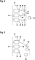
- Fig. 2 shows a part of an arm 16 of the converter 10. Every converter cell 18 comprises a photovoltaic cell 28 that, for example, is attached to a housing of the converter cell 18. When light 30 is radiated onto the photovoltaic cell 28, the photovoltaic cell 28 produces a voltage that may be supplied to the converter cell 18 and/or may be used for supplying the converter cell 18 with auxiliary power.
- the series-connected converter cells 18 are provided in stacks in a hall, in which the converter 10 is arranged. These stacks need to be galvanically isolated with respect to the high voltages processed by the converter 10. Furthermore, during operation of the converter 10, each converter cell 18 is floating on an electrical potential that may be up to the maximal voltage processed by the converter 10. Also the respective photovoltaic cell 28, which is not galvanically isolated from the rest of the converter cell 18 with respect to this high voltage, is floating on this potential.
- artificial light sources 32 may be provided distant from the photovoltaic cells 28.
- the distance may be as high, such that the light sources 32 may be grounded.
- a wireless power transfer may be performed via light 30 from the artificial light source 32, which may be controlled, such as switched on and off, by the central controller 26.
- the light sources 32 may be connected to a floor and/or a roof of the hall accommodating the converter 10. It has to be noted that the converter cells 18, the stack of converter cells 18 and/or the hall may have to be designed to allow beaming light 30 directly onto the photovoltaic cells 28.
- the light sources 32 and/or the beam of light 32 generated by them may be fixed.
- Fig. 3 shows, that one or more light sources 32' (here a laser) may be movable in such a way that a beam of light (here a laser beam) 30' may be directed onto different converter cells 18 at different times. In such a way, light 30' may be radiated sequentially onto the converter cells 18. The movement of the light source 32' may be controlled by the central controller 26.
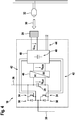
- Fig. 4 shows a converter cell 18 in more detail.
- the converter cell 18 comprises a cell capacitor 24, which is electrically connectable with semiconductor switches 34 between two outputs 36 of the converter cell 18.
- the semiconductor switches 34 are connected in series with each other and in parallel to the cell capacitor 24.
- One output 36 of the converter cell 18 is provided on an end of the series-connection and the other output is provided between the semiconductor switches 34.
- a free-wheeling diode 38 may be connected anti-parallel to each semiconductor switch 34.
- the semiconductor switches 34 may be IGBTs, i.e. normally-off devices. However, the semiconductor switches 34 also may be normally-off devices, such as SiC JFETs. Furthermore, the semiconductor switches 34 may be based on Si substrate or a wide bandgap substrate. For example, the semiconductor switches 34 may be SiC-JFETs, which may provide a rather high voltage blocking capability of more than 10 kV.
- the converter cell 18 furthermore comprises a cell controller 40, which may comprise control electronics, sensors, gate drivers, etc.
- the cell controller 40 is adapted for providing the gate signals 42 for the semiconductor switches 34. Via a link 44, the cell controller may communicate with the central controller 26.
- the cell controller 40 may further comprise a network interface for connecting the device to a data network, in particular a global data network.
- the data network may be a TCP/IP network such as Internet.
- the cell controller 40 is operatively connected to the network interface for carrying out commands received from the data network.
- the commands may include a control command for controlling the device to carry out a task such as bypassing the cell, health monitoring, documenting system status.
- the controller is adapted for carrying out the task in response to the control command.
- the commands may include a status request.
- the cell controller 40 may be adapted for sending a status information to the network interface, and the network interface is then adapted for sending the status information over the network.
- the commands may include an update command including update data.
- the cell controller 40 is adapted for initiating an update in response to the update command and using the update data.
- a DC/DC converter 46 which is interconnected between the cell capacitor 24 and the cell controller 40, is adapted for converting the cell capacitor voltage U CELL of the cell capacitor 24 into an auxiliary voltage U AUX for the controller 40.
- the auxiliary power supplied to the controller 40 may be stored in an auxiliary power capacitor 48.
- the voltage U PV of the photovoltaic cell 28 may be supplied to the controller 40 and/or stored on the auxiliary power capacitor 48.
- the cell capacitor voltage U CELL may be about 3 kV and the auxiliary voltage U AUX may be about 24 V.
- the voltage U PV of the photovoltaic cell 28 may be in this range, i.e. lower than 30 V.
- the controller 40 is supplied by the cell capacitor 24 with auxiliary power.
- the controller 40 switches a cell current through the converter cell 18 by switching the one or more semiconductor switches 34 in such a way that the cell capacitor 24 is loaded.
- the cell capacitor voltage U CELL is converted by the DC/DC converter 46 into the supply voltage U AUX for the controller 40 and/or may be stored in the auxiliary power capacitor 48.
- the photovoltaic cell 28 may be electrically disconnected from the controller 40.
- a protection mechanism such as a diode, may be placed between the photovoltaic cell 28 and the controller 40, in order to disconnect the photovoltaic cell 28 after the converter cell 18 is pre-charged during normal operation.
- the controller 40 may be supplied from the photovoltaic cell 28 and/or the auxiliary power capacitor 48 may be charged with the photovoltaic cell 28.
- the light sources 32 may be switched on by the central controller 26 and light 30 may be radiated onto the photovoltaic cells 28.
- the controller 40 may start operation. In the case of normally-on switches 34, the controller 40 may switch the switches 34 into a blocking state. After that, all converter cells 18 are blocking and a pre-charging of the cell capacitors 24 via the voltage at the inputs 14 of the converter may be started.
- the DC/DC converter 46 may convert the voltage U PV from the photovoltaic cell 28 into a voltage supplied to the cell capacitor 24.
- the auxiliary power from the photovoltaic cell 28 may be used in a failure operation mode of a converter module.
- this failure may be indicated to the central controller 26, which then may start to radiate light 30 on the specific converter cell 18. This may be performed as described with respect to Fig. 3 .
- the controller 40 of the failed converter cell 18 may be supplied with a voltage from the photovoltaic cell 28, such that the controller 40 continues operating. For example, the controller 40 may continue to gather sensor data and may send this to the central controller 26.
Landscapes
- Engineering & Computer Science (AREA)
- Power Engineering (AREA)
- Charge And Discharge Circuits For Batteries Or The Like (AREA)
- Inverter Devices (AREA)
Claims (13)
- Convertisseur modulaire (10), comprenant :
une pluralité de cellules (18) de convertisseur connectées en série, chaque cellule (18) de convertisseur comprenant :au moins un commutateur de puissance à semiconducteur (34) destiné à commuter un courant de cellule au travers de la cellule (18) de convertisseur ;un condensateur (24) de cellule interconnecté avec l'au moins un commutateur de puissance à semiconducteur (34), de façon à permettre la charge du condensateur (24) de cellule par le courant de cellule ;une unité de commande (40) destinée à commuter l'au moins un commutateur de puissance à semiconducteur (34), l'unité de commande (40) étant susceptible d'être alimentée par une puissance auxiliaire issue du condensateur (24) de cellule ;une cellule photovoltaïque (28) destinée à fournir une puissance auxiliaire supplémentaire à l'unité de commande ;un convertisseur continu-continu (46) conçu pour convertir une tension issue de la cellule photovoltaïque (28) en une tension alimentant le condensateur (24) de cellule ;le convertisseur modulaire comprenant au moins une source de lumière (32), laquelle est séparée galvaniquement des cellules (18) de convertisseur et laquelle est adaptée à rayonner de la lumière (30) sur une ou plusieurs des cellules photovoltaïques (28) des cellules (18) de convertisseur. - Convertisseur modulaire (10) selon la revendication 1,
dans lequel, lors du fonctionnement de la cellule (18) de convertisseur, la cellule photovoltaïque (28) n'est pas isolée galvaniquement du reste de la cellule (18) de convertisseur. - Convertisseur modulaire (10) selon la revendication 1 ou 2, dans lequel la cellule de convertisseur comprend un condensateur de puissance auxiliaire (48) destiné à stocker une puissance auxiliaire pour l'unité de commande (40) et destiné à recevoir une puissance auxiliaire issue du condensateur (24) de cellule et de la cellule photovoltaïque (28).
- Convertisseur modulaire (10) selon l'une des revendications précédentes, dans lequel le convertisseur continu-continu (46) est adapté à convertir une tension de condensateur de cellule du condensateur (24) de cellule en une tension d'alimentation pour l'unité de commande (40).
- Convertisseur modulaire (10) selon l'une des revendications précédentes,
dans lequel l'au moins un commutateur de puissance à semiconducteur (34) est un commutateur normalement passant. - Convertisseur modulaire (10) selon l'une des revendications précédentes,
dans lequel l'au moins un commutateur de puissance à semiconducteur (34) est basé sur un substrat à large bande interdite. - Convertisseur modulaire (10) selon l'une des revendications précédentes,
dans lequel l'unité de commande (40) de cellule comprend une interface réseau destinée à connecter le dispositif à un réseau de données,
dans lequel l'unité de commande (40) de cellule est connectée fonctionnellement à l'interface réseau pour exécuter des commandes reçues du réseau de données et/ou envoyer des informations d'état de dispositif au réseau de données. - Convertisseur modulaire (10) selon l'une des revendications précédentes, comprenant en outre :
une pluralité de sources de lumière (32), chaque source de lumière (32) étant associée à une ou plusieurs cellules photovoltaïques (28). - Convertisseur modulaire (10) selon l'une des revendications précédentes,
dans lequel l'au moins une source de lumière (32') comprend un laser. - Convertisseur modulaire (10) selon l'une des revendications précédentes, comprenant en outre :
au moins une source de lumière mobile (32'), de façon à permettre l'alimentation séquentielle de cellules (18) de convertisseur et/ou de groupes de cellules (18) de convertisseur par l'au moins une source de lumière mobile (32'). - Procédé de fonctionnement d'un convertisseur modulaire (10) selon l'une des revendications précédentes, le procédé comprenant :le rayonnement de lumière sur des cellules photovoltaïques (28) des cellules (18) de convertisseur ;l'alimentation des unités de commande (40) des cellules (18) de convertisseur par une tension issue des cellules photovoltaïques (28).
- Procédé selon la revendication 11,
dans lequel les commutateurs à semiconducteur (34) des cellules (18) de convertisseur comprennent des commutateurs normalement passants, et lequel procédé comprend :le rayonnement de lumière (30) sur les cellules photovoltaïques (28) au cours d'un démarrage du convertisseur (10) ;la commutation de l'au moins un commutateur normalement passant (34) d'une cellule (18) de convertisseur sur un état bloquant par l'unité de commande (40) de la cellule (18) de convertisseur, laquelle est alimentée par la cellule photovoltaïque (28). - Procédé selon la revendication 11 ou 12, comprenant en outre :la détection d'une défaillance dans une cellule (18) de convertisseur ;le rayonnement de lumière (30) sur la cellule photovoltaïque (28) de la cellule (18) de convertisseur défaillante et l'alimentation de l'unité de commande (40) de la cellule (18) de convertisseur défaillante par une tension issue de la cellule photovoltaïque (28), de sorte que l'unité de commande (40) continue de fonctionner sans alimentation en puissance par le condensateur (24) de cellule.
Applications Claiming Priority (1)
| Application Number | Priority Date | Filing Date | Title |
|---|---|---|---|
| LU100268 | 2017-05-30 |
Publications (2)
| Publication Number | Publication Date |
|---|---|
| EP3410592A1 EP3410592A1 (fr) | 2018-12-05 |
| EP3410592B1 true EP3410592B1 (fr) | 2019-12-25 |
Family
ID=59055244
Family Applications (1)
| Application Number | Title | Priority Date | Filing Date |
|---|---|---|---|
| EP18175153.8A Active EP3410592B1 (fr) | 2017-05-30 | 2018-05-30 | Cellule de convertisseur à cellule photovoltaïque intégrée |
Country Status (3)
| Country | Link |
|---|---|
| US (1) | US10673353B2 (fr) |
| EP (1) | EP3410592B1 (fr) |
| CN (1) | CN108988631B (fr) |
Families Citing this family (6)
| Publication number | Priority date | Publication date | Assignee | Title |
|---|---|---|---|---|
| US9312701B1 (en) * | 2015-07-16 | 2016-04-12 | Wi-Charge Ltd | System for optical wireless power supply |
| WO2018193606A1 (fr) * | 2017-04-21 | 2018-10-25 | 東芝三菱電機産業システム株式会社 | Dispositif de conversion de puissance |
| EP3654510A1 (fr) * | 2018-11-19 | 2020-05-20 | Maschinenfabrik Reinhausen GmbH | Précharge d'un convertisseur multiniveaux modulairemodulaires à plusieurs niveaux |
| CN109921454B (zh) * | 2019-04-17 | 2021-05-28 | 国家电网有限公司 | 基于模块化多电平换流器的柔性直流系统启动方法及装置 |
| CN114731117B (zh) * | 2019-09-19 | 2026-03-10 | 维斯塔斯风力系统集团公司 | 模块化多电平变流器中的同步电网侧谐波滤波器和预充电电池电容器 |
| US12549096B2 (en) | 2024-01-09 | 2026-02-10 | Delta Electronics, Inc. | Converter system |
Family Cites Families (17)
| Publication number | Priority date | Publication date | Assignee | Title |
|---|---|---|---|---|
| DE2631194B2 (de) * | 1976-07-10 | 1979-03-08 | Friedhelm Dipl.-Ing. 4630 Bochum Caspers | Anordnung zur Zuführung von Versorgungsenergie an ein MeB- und Nachrichtengerät in einer Hochspannungsanlage |
| SE515702C2 (sv) | 1996-12-17 | 2001-09-24 | Abb Ab | Anordning och förfarande för att skydda ett objekt mot felrelaterade överströmmar (Fall 3) |
| GB2345129A (en) | 1998-12-21 | 2000-06-28 | Asea Brown Boveri | Optical Sensor Using Polarised Light |
| US9442504B2 (en) * | 2009-04-17 | 2016-09-13 | Ampt, Llc | Methods and apparatus for adaptive operation of solar power systems |
| JP5378274B2 (ja) * | 2010-03-15 | 2013-12-25 | 株式会社日立製作所 | 電力変換装置 |
| WO2012167835A1 (fr) * | 2011-06-10 | 2012-12-13 | Abb Technology Ag | Procédé pour alimenter en énergie un convertisseur à maillon de chaîne, unité de commande, programmes informatiques et produits de programme informatique |
| CN202602532U (zh) * | 2012-02-24 | 2012-12-12 | 武汉朝日晟科技有限公司 | 用于光伏并网逆变器的辅助电源装置 |
| EP2680421B2 (fr) | 2012-06-29 | 2018-08-08 | Siemens Aktiengesellschaft | Convertisseur de fréquence doté d'un condensateur de circuit intermédiaire et procédé de pré-charge de celui-ci |
| WO2015155112A1 (fr) * | 2014-04-07 | 2015-10-15 | Abb Technology Ag | Convertisseur modulaire multiniveaux à cellules de convertisseur redondantes en mode veille |
| DE102014217911A1 (de) | 2014-09-08 | 2016-03-10 | Siemens Aktiengesellschaft | Anordnung und Verfahren zur galvanisch getrennten Energieübertragung |
| CN204144967U (zh) * | 2014-09-16 | 2015-02-04 | 安徽理工大学 | 基于mmc的大型光伏并网系统 |
| KR101711948B1 (ko) | 2014-12-29 | 2017-03-03 | 주식회사 효성 | Mmc 컨버터의 서브모듈용 전원제어장치 |
| GB2537868B (en) | 2015-04-29 | 2021-02-17 | General Electric Technology Gmbh | Powering voltage source converters |
| CN104914290A (zh) | 2015-06-23 | 2015-09-16 | 上海久能机电制造有限公司 | 一种光伏供电的电流变送器 |
| CN106329899B (zh) * | 2015-07-01 | 2018-10-16 | 南京南瑞继保电气有限公司 | 故障电流抑制阻尼器拓扑电路及其控制方法及换流器 |
| CN105680686A (zh) * | 2015-08-03 | 2016-06-15 | 许昌开普电气研究院 | 基于mmc的光伏发电系统新型拓扑结构 |
| JP7221877B2 (ja) | 2017-04-28 | 2023-02-14 | ヒタチ・エナジー・スウィツァーランド・アクチェンゲゼルシャフト | ノーマリオンの半導体スイッチに基づく電源モジュール |
-
2018
- 2018-05-30 EP EP18175153.8A patent/EP3410592B1/fr active Active
- 2018-05-30 CN CN201810539196.XA patent/CN108988631B/zh active Active
- 2018-05-30 US US15/993,019 patent/US10673353B2/en active Active
Non-Patent Citations (1)
| Title |
|---|
| None * |
Also Published As
| Publication number | Publication date |
|---|---|
| EP3410592A1 (fr) | 2018-12-05 |
| US10673353B2 (en) | 2020-06-02 |
| CN108988631B (zh) | 2024-05-14 |
| US20180351474A1 (en) | 2018-12-06 |
| CN108988631A (zh) | 2018-12-11 |
Similar Documents
| Publication | Publication Date | Title |
|---|---|---|
| EP3410592B1 (fr) | Cellule de convertisseur à cellule photovoltaïque intégrée | |
| US11088612B2 (en) | Flexible bootstrapping for power electronics circuits | |
| EP2795780B1 (fr) | Démarrage autonome d'un convertisseur modulaire multi-niveaux de source de tension | |
| CN102714471B (zh) | 用于对储能器充电和放电的变流器和变流器的子模块 | |
| US9812990B1 (en) | Spare on demand power cells for modular multilevel power converter | |
| JP6921319B2 (ja) | 電力変換装置 | |
| EP3242387B1 (fr) | Appareil de commande d'alimentation pour sous-module de convertisseur mmc | |
| KR101698401B1 (ko) | 냉각 부재를 포함하는 에너지 저장 장치, 및 에너지 저장 셀의 냉각 방법 | |
| US10797586B2 (en) | Power module based on normally-on semiconductor switches | |
| WO2015155112A1 (fr) | Convertisseur modulaire multiniveaux à cellules de convertisseur redondantes en mode veille | |
| US20160352239A1 (en) | Power electronic converter | |
| WO2011120572A1 (fr) | Convertisseur | |
| WO2016108571A1 (fr) | Appareil d'alimentation électrique pour sous-module de mmc | |
| WO2020165954A1 (fr) | Dispositif de conversion de puissance et système de conversion de puissance | |
| EP3621193B1 (fr) | Fonction de mode de défaillance de court-circuit stable artificiel à l'aide de modules parallèles pour chaque fonction de commutation | |
| EP4274078B1 (fr) | Convertisseur de puissance partiel cc-cc à topologie contrôlable | |
| CN110710089B (zh) | 用于电压源转换器的接地布置 | |
| CN105322609B (zh) | 用于提供电压的装置以及驱动布置和方法 | |
| US11817767B2 (en) | Control power for submodules of a MMC converter | |
| CN112868179A (zh) | 电子阀装置 | |
| EP3940936A1 (fr) | Convertisseur électrique doté d'une fonction de dérivation | |
| KR20250165515A (ko) | 전력변환장치 |
Legal Events
| Date | Code | Title | Description |
|---|---|---|---|
| PUAI | Public reference made under article 153(3) epc to a published international application that has entered the european phase |
Free format text: ORIGINAL CODE: 0009012 |
|
| STAA | Information on the status of an ep patent application or granted ep patent |
Free format text: STATUS: THE APPLICATION HAS BEEN PUBLISHED |
|
| AK | Designated contracting states |
Kind code of ref document: A1 Designated state(s): AL AT BE BG CH CY CZ DE DK EE ES FI FR GB GR HR HU IE IS IT LI LT LU LV MC MK MT NL NO PL PT RO RS SE SI SK SM TR |
|
| AX | Request for extension of the european patent |
Extension state: BA ME |
|
| STAA | Information on the status of an ep patent application or granted ep patent |
Free format text: STATUS: REQUEST FOR EXAMINATION WAS MADE |
|
| 17P | Request for examination filed |
Effective date: 20190507 |
|
| RBV | Designated contracting states (corrected) |
Designated state(s): AL AT BE BG CH CY CZ DE DK EE ES FI FR GB GR HR HU IE IS IT LI LT LU LV MC MK MT NL NO PL PT RO RS SE SI SK SM TR |
|
| GRAP | Despatch of communication of intention to grant a patent |
Free format text: ORIGINAL CODE: EPIDOSNIGR1 |
|
| STAA | Information on the status of an ep patent application or granted ep patent |
Free format text: STATUS: GRANT OF PATENT IS INTENDED |
|
| RIC1 | Information provided on ipc code assigned before grant |
Ipc: H02M 1/32 20070101ALI20190617BHEP Ipc: H02M 7/483 20070101ALI20190617BHEP Ipc: H02M 1/36 20070101AFI20190617BHEP |
|
| INTG | Intention to grant announced |
Effective date: 20190724 |
|
| GRAS | Grant fee paid |
Free format text: ORIGINAL CODE: EPIDOSNIGR3 |
|
| GRAA | (expected) grant |
Free format text: ORIGINAL CODE: 0009210 |
|
| STAA | Information on the status of an ep patent application or granted ep patent |
Free format text: STATUS: THE PATENT HAS BEEN GRANTED |
|
| AK | Designated contracting states |
Kind code of ref document: B1 Designated state(s): AL AT BE BG CH CY CZ DE DK EE ES FI FR GB GR HR HU IE IS IT LI LT LU LV MC MK MT NL NO PL PT RO RS SE SI SK SM TR |
|
| REG | Reference to a national code |
Ref country code: GB Ref legal event code: FG4D |
|
| REG | Reference to a national code |
Ref country code: CH Ref legal event code: EP |
|
| REG | Reference to a national code |
Ref country code: AT Ref legal event code: REF Ref document number: 1218240 Country of ref document: AT Kind code of ref document: T Effective date: 20200115 |
|
| REG | Reference to a national code |
Ref country code: DE Ref legal event code: R096 Ref document number: 602018001766 Country of ref document: DE |
|
| REG | Reference to a national code |
Ref country code: IE Ref legal event code: FG4D |
|
| REG | Reference to a national code |
Ref country code: NL Ref legal event code: MP Effective date: 20191225 |
|
| PG25 | Lapsed in a contracting state [announced via postgrant information from national office to epo] |
Ref country code: NO Free format text: LAPSE BECAUSE OF FAILURE TO SUBMIT A TRANSLATION OF THE DESCRIPTION OR TO PAY THE FEE WITHIN THE PRESCRIBED TIME-LIMIT Effective date: 20200325 Ref country code: LT Free format text: LAPSE BECAUSE OF FAILURE TO SUBMIT A TRANSLATION OF THE DESCRIPTION OR TO PAY THE FEE WITHIN THE PRESCRIBED TIME-LIMIT Effective date: 20191225 Ref country code: GR Free format text: LAPSE BECAUSE OF FAILURE TO SUBMIT A TRANSLATION OF THE DESCRIPTION OR TO PAY THE FEE WITHIN THE PRESCRIBED TIME-LIMIT Effective date: 20200326 Ref country code: LV Free format text: LAPSE BECAUSE OF FAILURE TO SUBMIT A TRANSLATION OF THE DESCRIPTION OR TO PAY THE FEE WITHIN THE PRESCRIBED TIME-LIMIT Effective date: 20191225 Ref country code: SE Free format text: LAPSE BECAUSE OF FAILURE TO SUBMIT A TRANSLATION OF THE DESCRIPTION OR TO PAY THE FEE WITHIN THE PRESCRIBED TIME-LIMIT Effective date: 20191225 Ref country code: FI Free format text: LAPSE BECAUSE OF FAILURE TO SUBMIT A TRANSLATION OF THE DESCRIPTION OR TO PAY THE FEE WITHIN THE PRESCRIBED TIME-LIMIT Effective date: 20191225 Ref country code: BG Free format text: LAPSE BECAUSE OF FAILURE TO SUBMIT A TRANSLATION OF THE DESCRIPTION OR TO PAY THE FEE WITHIN THE PRESCRIBED TIME-LIMIT Effective date: 20200325 |
|
| REG | Reference to a national code |
Ref country code: LT Ref legal event code: MG4D |
|
| PG25 | Lapsed in a contracting state [announced via postgrant information from national office to epo] |
Ref country code: HR Free format text: LAPSE BECAUSE OF FAILURE TO SUBMIT A TRANSLATION OF THE DESCRIPTION OR TO PAY THE FEE WITHIN THE PRESCRIBED TIME-LIMIT Effective date: 20191225 Ref country code: RS Free format text: LAPSE BECAUSE OF FAILURE TO SUBMIT A TRANSLATION OF THE DESCRIPTION OR TO PAY THE FEE WITHIN THE PRESCRIBED TIME-LIMIT Effective date: 20191225 |
|
| PG25 | Lapsed in a contracting state [announced via postgrant information from national office to epo] |
Ref country code: AL Free format text: LAPSE BECAUSE OF FAILURE TO SUBMIT A TRANSLATION OF THE DESCRIPTION OR TO PAY THE FEE WITHIN THE PRESCRIBED TIME-LIMIT Effective date: 20191225 |
|
| PG25 | Lapsed in a contracting state [announced via postgrant information from national office to epo] |
Ref country code: PT Free format text: LAPSE BECAUSE OF FAILURE TO SUBMIT A TRANSLATION OF THE DESCRIPTION OR TO PAY THE FEE WITHIN THE PRESCRIBED TIME-LIMIT Effective date: 20200520 Ref country code: NL Free format text: LAPSE BECAUSE OF FAILURE TO SUBMIT A TRANSLATION OF THE DESCRIPTION OR TO PAY THE FEE WITHIN THE PRESCRIBED TIME-LIMIT Effective date: 20191225 Ref country code: RO Free format text: LAPSE BECAUSE OF FAILURE TO SUBMIT A TRANSLATION OF THE DESCRIPTION OR TO PAY THE FEE WITHIN THE PRESCRIBED TIME-LIMIT Effective date: 20191225 Ref country code: CZ Free format text: LAPSE BECAUSE OF FAILURE TO SUBMIT A TRANSLATION OF THE DESCRIPTION OR TO PAY THE FEE WITHIN THE PRESCRIBED TIME-LIMIT Effective date: 20191225 Ref country code: EE Free format text: LAPSE BECAUSE OF FAILURE TO SUBMIT A TRANSLATION OF THE DESCRIPTION OR TO PAY THE FEE WITHIN THE PRESCRIBED TIME-LIMIT Effective date: 20191225 |
|
| PG25 | Lapsed in a contracting state [announced via postgrant information from national office to epo] |
Ref country code: IS Free format text: LAPSE BECAUSE OF FAILURE TO SUBMIT A TRANSLATION OF THE DESCRIPTION OR TO PAY THE FEE WITHIN THE PRESCRIBED TIME-LIMIT Effective date: 20200425 Ref country code: SK Free format text: LAPSE BECAUSE OF FAILURE TO SUBMIT A TRANSLATION OF THE DESCRIPTION OR TO PAY THE FEE WITHIN THE PRESCRIBED TIME-LIMIT Effective date: 20191225 Ref country code: SM Free format text: LAPSE BECAUSE OF FAILURE TO SUBMIT A TRANSLATION OF THE DESCRIPTION OR TO PAY THE FEE WITHIN THE PRESCRIBED TIME-LIMIT Effective date: 20191225 |
|
| REG | Reference to a national code |
Ref country code: DE Ref legal event code: R097 Ref document number: 602018001766 Country of ref document: DE |
|
| PG25 | Lapsed in a contracting state [announced via postgrant information from national office to epo] |
Ref country code: ES Free format text: LAPSE BECAUSE OF FAILURE TO SUBMIT A TRANSLATION OF THE DESCRIPTION OR TO PAY THE FEE WITHIN THE PRESCRIBED TIME-LIMIT Effective date: 20191225 Ref country code: DK Free format text: LAPSE BECAUSE OF FAILURE TO SUBMIT A TRANSLATION OF THE DESCRIPTION OR TO PAY THE FEE WITHIN THE PRESCRIBED TIME-LIMIT Effective date: 20191225 |
|
| PLBE | No opposition filed within time limit |
Free format text: ORIGINAL CODE: 0009261 |
|
| STAA | Information on the status of an ep patent application or granted ep patent |
Free format text: STATUS: NO OPPOSITION FILED WITHIN TIME LIMIT |
|
| REG | Reference to a national code |
Ref country code: AT Ref legal event code: MK05 Ref document number: 1218240 Country of ref document: AT Kind code of ref document: T Effective date: 20191225 |
|
| PG25 | Lapsed in a contracting state [announced via postgrant information from national office to epo] |
Ref country code: SI Free format text: LAPSE BECAUSE OF FAILURE TO SUBMIT A TRANSLATION OF THE DESCRIPTION OR TO PAY THE FEE WITHIN THE PRESCRIBED TIME-LIMIT Effective date: 20191225 |
|
| 26N | No opposition filed |
Effective date: 20200928 |
|
| PG25 | Lapsed in a contracting state [announced via postgrant information from national office to epo] |
Ref country code: MC Free format text: LAPSE BECAUSE OF FAILURE TO SUBMIT A TRANSLATION OF THE DESCRIPTION OR TO PAY THE FEE WITHIN THE PRESCRIBED TIME-LIMIT Effective date: 20191225 Ref country code: AT Free format text: LAPSE BECAUSE OF FAILURE TO SUBMIT A TRANSLATION OF THE DESCRIPTION OR TO PAY THE FEE WITHIN THE PRESCRIBED TIME-LIMIT Effective date: 20191225 Ref country code: IT Free format text: LAPSE BECAUSE OF FAILURE TO SUBMIT A TRANSLATION OF THE DESCRIPTION OR TO PAY THE FEE WITHIN THE PRESCRIBED TIME-LIMIT Effective date: 20191225 |
|
| PG25 | Lapsed in a contracting state [announced via postgrant information from national office to epo] |
Ref country code: PL Free format text: LAPSE BECAUSE OF FAILURE TO SUBMIT A TRANSLATION OF THE DESCRIPTION OR TO PAY THE FEE WITHIN THE PRESCRIBED TIME-LIMIT Effective date: 20191225 |
|
| REG | Reference to a national code |
Ref country code: BE Ref legal event code: MM Effective date: 20200531 |
|
| PG25 | Lapsed in a contracting state [announced via postgrant information from national office to epo] |
Ref country code: LU Free format text: LAPSE BECAUSE OF NON-PAYMENT OF DUE FEES Effective date: 20200530 |
|
| PG25 | Lapsed in a contracting state [announced via postgrant information from national office to epo] |
Ref country code: IE Free format text: LAPSE BECAUSE OF NON-PAYMENT OF DUE FEES Effective date: 20200530 |
|
| REG | Reference to a national code |
Ref country code: DE Ref legal event code: R081 Ref document number: 602018001766 Country of ref document: DE Owner name: HITACHI ENERGY SWITZERLAND AG, CH Free format text: FORMER OWNER: ABB SCHWEIZ AG, BADEN, CH Ref country code: DE Ref legal event code: R081 Ref document number: 602018001766 Country of ref document: DE Owner name: HITACHI ENERGY LTD, CH Free format text: FORMER OWNER: ABB SCHWEIZ AG, BADEN, CH Ref country code: DE Ref legal event code: R081 Ref document number: 602018001766 Country of ref document: DE Owner name: ABB POWER GRIDS SWITZERLAND AG, CH Free format text: FORMER OWNER: ABB SCHWEIZ AG, BADEN, CH |
|
| PG25 | Lapsed in a contracting state [announced via postgrant information from national office to epo] |
Ref country code: BE Free format text: LAPSE BECAUSE OF NON-PAYMENT OF DUE FEES Effective date: 20200531 |
|
| REG | Reference to a national code |
Ref country code: GB Ref legal event code: 732E Free format text: REGISTERED BETWEEN 20211104 AND 20211110 |
|
| REG | Reference to a national code |
Ref country code: CH Ref legal event code: PL |
|
| PG25 | Lapsed in a contracting state [announced via postgrant information from national office to epo] |
Ref country code: LI Free format text: LAPSE BECAUSE OF NON-PAYMENT OF DUE FEES Effective date: 20210531 Ref country code: CH Free format text: LAPSE BECAUSE OF NON-PAYMENT OF DUE FEES Effective date: 20210531 |
|
| PG25 | Lapsed in a contracting state [announced via postgrant information from national office to epo] |
Ref country code: TR Free format text: LAPSE BECAUSE OF FAILURE TO SUBMIT A TRANSLATION OF THE DESCRIPTION OR TO PAY THE FEE WITHIN THE PRESCRIBED TIME-LIMIT Effective date: 20191225 Ref country code: MT Free format text: LAPSE BECAUSE OF FAILURE TO SUBMIT A TRANSLATION OF THE DESCRIPTION OR TO PAY THE FEE WITHIN THE PRESCRIBED TIME-LIMIT Effective date: 20191225 Ref country code: CY Free format text: LAPSE BECAUSE OF FAILURE TO SUBMIT A TRANSLATION OF THE DESCRIPTION OR TO PAY THE FEE WITHIN THE PRESCRIBED TIME-LIMIT Effective date: 20191225 |
|
| REG | Reference to a national code |
Ref country code: DE Ref legal event code: R081 Ref document number: 602018001766 Country of ref document: DE Owner name: HITACHI ENERGY SWITZERLAND AG, CH Free format text: FORMER OWNER: ABB POWER GRIDS SWITZERLAND AG, BADEN, CH Ref country code: DE Ref legal event code: R081 Ref document number: 602018001766 Country of ref document: DE Owner name: HITACHI ENERGY LTD, CH Free format text: FORMER OWNER: ABB POWER GRIDS SWITZERLAND AG, BADEN, CH |
|
| PG25 | Lapsed in a contracting state [announced via postgrant information from national office to epo] |
Ref country code: MK Free format text: LAPSE BECAUSE OF FAILURE TO SUBMIT A TRANSLATION OF THE DESCRIPTION OR TO PAY THE FEE WITHIN THE PRESCRIBED TIME-LIMIT Effective date: 20191225 |
|
| P01 | Opt-out of the competence of the unified patent court (upc) registered |
Effective date: 20230527 |
|
| REG | Reference to a national code |
Ref country code: DE Ref legal event code: R082 Ref document number: 602018001766 Country of ref document: DE Representative=s name: DENNEMEYER & ASSOCIATES RECHTSANWALTSGESELLSCH, DE Ref country code: DE Ref legal event code: R082 Ref document number: 602018001766 Country of ref document: DE Representative=s name: DENNEMEYER & ASSOCIATES S.A., DE Ref country code: DE Ref legal event code: R081 Ref document number: 602018001766 Country of ref document: DE Owner name: HITACHI ENERGY LTD, CH Free format text: FORMER OWNER: HITACHI ENERGY SWITZERLAND AG, BADEN, CH |
|
| REG | Reference to a national code |
Ref country code: GB Ref legal event code: 732E Free format text: REGISTERED BETWEEN 20240718 AND 20240724 |
|
| REG | Reference to a national code |
Ref country code: DE Ref legal event code: R082 Ref document number: 602018001766 Country of ref document: DE Representative=s name: DENNEMEYER & ASSOCIATES RECHTSANWALTSGESELLSCH, DE |
|
| PGFP | Annual fee paid to national office [announced via postgrant information from national office to epo] |
Ref country code: DE Payment date: 20250521 Year of fee payment: 8 |
|
| PGFP | Annual fee paid to national office [announced via postgrant information from national office to epo] |
Ref country code: GB Payment date: 20250527 Year of fee payment: 8 |
|
| PGFP | Annual fee paid to national office [announced via postgrant information from national office to epo] |
Ref country code: FR Payment date: 20250528 Year of fee payment: 8 |