EP3412909B1 - System und verfahren zur verringerung von windturbinenlärm bei starkwindbedingungen - Google Patents
System und verfahren zur verringerung von windturbinenlärm bei starkwindbedingungen Download PDFInfo
- Publication number
- EP3412909B1 EP3412909B1 EP18176306.1A EP18176306A EP3412909B1 EP 3412909 B1 EP3412909 B1 EP 3412909B1 EP 18176306 A EP18176306 A EP 18176306A EP 3412909 B1 EP3412909 B1 EP 3412909B1
- Authority
- EP
- European Patent Office
- Prior art keywords
- wind
- wind turbine
- wind speed
- nacelle
- yaw
- Prior art date
- Legal status (The legal status is an assumption and is not a legal conclusion. Google has not performed a legal analysis and makes no representation as to the accuracy of the status listed.)
- Active
Links
Images




Classifications
-
- F—MECHANICAL ENGINEERING; LIGHTING; HEATING; WEAPONS; BLASTING
- F03—MACHINES OR ENGINES FOR LIQUIDS; WIND, SPRING, OR WEIGHT MOTORS; PRODUCING MECHANICAL POWER OR A REACTIVE PROPULSIVE THRUST, NOT OTHERWISE PROVIDED FOR
- F03D—WIND MOTORS
- F03D7/00—Controlling wind motors
- F03D7/02—Controlling wind motors the wind motors having rotation axis substantially parallel to the air flow entering the rotor
- F03D7/0296—Controlling wind motors the wind motors having rotation axis substantially parallel to the air flow entering the rotor to prevent, counteract or reduce noise emissions
-
- F—MECHANICAL ENGINEERING; LIGHTING; HEATING; WEAPONS; BLASTING
- F03—MACHINES OR ENGINES FOR LIQUIDS; WIND, SPRING, OR WEIGHT MOTORS; PRODUCING MECHANICAL POWER OR A REACTIVE PROPULSIVE THRUST, NOT OTHERWISE PROVIDED FOR
- F03D—WIND MOTORS
- F03D7/00—Controlling wind motors
- F03D7/02—Controlling wind motors the wind motors having rotation axis substantially parallel to the air flow entering the rotor
- F03D7/0204—Controlling wind motors the wind motors having rotation axis substantially parallel to the air flow entering the rotor for orientation in relation to wind direction
-
- G—PHYSICS
- G05—CONTROLLING; REGULATING
- G05B—CONTROL OR REGULATING SYSTEMS IN GENERAL; FUNCTIONAL ELEMENTS OF SUCH SYSTEMS; MONITORING OR TESTING ARRANGEMENTS FOR SUCH SYSTEMS OR ELEMENTS
- G05B19/00—Program-control systems
- G05B19/02—Program-control systems electric
- G05B19/18—Numerical control [NC], i.e. automatically operating machines, in particular machine tools, e.g. in a manufacturing environment, so as to execute positioning, movement or co-ordinated operations by means of program data in numerical form
- G05B19/402—Numerical control [NC], i.e. automatically operating machines, in particular machine tools, e.g. in a manufacturing environment, so as to execute positioning, movement or co-ordinated operations by means of program data in numerical form characterised by control arrangements for positioning, e.g. centring a tool relative to a hole in the workpiece, additional detection means to correct position
-
- F—MECHANICAL ENGINEERING; LIGHTING; HEATING; WEAPONS; BLASTING
- F05—INDEXING SCHEMES RELATING TO ENGINES OR PUMPS IN VARIOUS SUBCLASSES OF CLASSES F01-F04
- F05B—INDEXING SCHEME RELATING TO WIND, SPRING, WEIGHT, INERTIA OR LIKE MOTORS, TO MACHINES OR ENGINES FOR LIQUIDS COVERED BY SUBCLASSES F03B, F03D AND F03G
- F05B2260/00—Function
- F05B2260/96—Preventing, counteracting or reducing vibration or noise
-
- F—MECHANICAL ENGINEERING; LIGHTING; HEATING; WEAPONS; BLASTING
- F05—INDEXING SCHEMES RELATING TO ENGINES OR PUMPS IN VARIOUS SUBCLASSES OF CLASSES F01-F04
- F05B—INDEXING SCHEME RELATING TO WIND, SPRING, WEIGHT, INERTIA OR LIKE MOTORS, TO MACHINES OR ENGINES FOR LIQUIDS COVERED BY SUBCLASSES F03B, F03D AND F03G
- F05B2270/00—Control
- F05B2270/30—Control parameters, e.g. input parameters
- F05B2270/32—Wind speeds
-
- F—MECHANICAL ENGINEERING; LIGHTING; HEATING; WEAPONS; BLASTING
- F05—INDEXING SCHEMES RELATING TO ENGINES OR PUMPS IN VARIOUS SUBCLASSES OF CLASSES F01-F04
- F05B—INDEXING SCHEME RELATING TO WIND, SPRING, WEIGHT, INERTIA OR LIKE MOTORS, TO MACHINES OR ENGINES FOR LIQUIDS COVERED BY SUBCLASSES F03B, F03D AND F03G
- F05B2270/00—Control
- F05B2270/30—Control parameters, e.g. input parameters
- F05B2270/321—Wind directions
-
- F—MECHANICAL ENGINEERING; LIGHTING; HEATING; WEAPONS; BLASTING
- F05—INDEXING SCHEMES RELATING TO ENGINES OR PUMPS IN VARIOUS SUBCLASSES OF CLASSES F01-F04
- F05B—INDEXING SCHEME RELATING TO WIND, SPRING, WEIGHT, INERTIA OR LIKE MOTORS, TO MACHINES OR ENGINES FOR LIQUIDS COVERED BY SUBCLASSES F03B, F03D AND F03G
- F05B2270/00—Control
- F05B2270/30—Control parameters, e.g. input parameters
- F05B2270/328—Blade pitch angle
-
- F—MECHANICAL ENGINEERING; LIGHTING; HEATING; WEAPONS; BLASTING
- F05—INDEXING SCHEMES RELATING TO ENGINES OR PUMPS IN VARIOUS SUBCLASSES OF CLASSES F01-F04
- F05B—INDEXING SCHEME RELATING TO WIND, SPRING, WEIGHT, INERTIA OR LIKE MOTORS, TO MACHINES OR ENGINES FOR LIQUIDS COVERED BY SUBCLASSES F03B, F03D AND F03G
- F05B2270/00—Control
- F05B2270/30—Control parameters, e.g. input parameters
- F05B2270/329—Azimuth or yaw angle
-
- F—MECHANICAL ENGINEERING; LIGHTING; HEATING; WEAPONS; BLASTING
- F05—INDEXING SCHEMES RELATING TO ENGINES OR PUMPS IN VARIOUS SUBCLASSES OF CLASSES F01-F04
- F05B—INDEXING SCHEME RELATING TO WIND, SPRING, WEIGHT, INERTIA OR LIKE MOTORS, TO MACHINES OR ENGINES FOR LIQUIDS COVERED BY SUBCLASSES F03B, F03D AND F03G
- F05B2270/00—Control
- F05B2270/30—Control parameters, e.g. input parameters
- F05B2270/333—Noise or sound levels
-
- F—MECHANICAL ENGINEERING; LIGHTING; HEATING; WEAPONS; BLASTING
- F05—INDEXING SCHEMES RELATING TO ENGINES OR PUMPS IN VARIOUS SUBCLASSES OF CLASSES F01-F04
- F05B—INDEXING SCHEME RELATING TO WIND, SPRING, WEIGHT, INERTIA OR LIKE MOTORS, TO MACHINES OR ENGINES FOR LIQUIDS COVERED BY SUBCLASSES F03B, F03D AND F03G
- F05B2270/00—Control
- F05B2270/70—Type of control algorithm
- F05B2270/708—Type of control algorithm with comparison tables
-
- F—MECHANICAL ENGINEERING; LIGHTING; HEATING; WEAPONS; BLASTING
- F05—INDEXING SCHEMES RELATING TO ENGINES OR PUMPS IN VARIOUS SUBCLASSES OF CLASSES F01-F04
- F05B—INDEXING SCHEME RELATING TO WIND, SPRING, WEIGHT, INERTIA OR LIKE MOTORS, TO MACHINES OR ENGINES FOR LIQUIDS COVERED BY SUBCLASSES F03B, F03D AND F03G
- F05B2270/00—Control
- F05B2270/80—Devices generating input signals, e.g. transducers, sensors, cameras or strain gauges
- F05B2270/804—Optical devices
- F05B2270/8042—Lidar systems
-
- F—MECHANICAL ENGINEERING; LIGHTING; HEATING; WEAPONS; BLASTING
- F05—INDEXING SCHEMES RELATING TO ENGINES OR PUMPS IN VARIOUS SUBCLASSES OF CLASSES F01-F04
- F05B—INDEXING SCHEME RELATING TO WIND, SPRING, WEIGHT, INERTIA OR LIKE MOTORS, TO MACHINES OR ENGINES FOR LIQUIDS COVERED BY SUBCLASSES F03B, F03D AND F03G
- F05B2270/00—Control
- F05B2270/80—Devices generating input signals, e.g. transducers, sensors, cameras or strain gauges
- F05B2270/807—Accelerometers
-
- G—PHYSICS
- G05—CONTROLLING; REGULATING
- G05B—CONTROL OR REGULATING SYSTEMS IN GENERAL; FUNCTIONAL ELEMENTS OF SUCH SYSTEMS; MONITORING OR TESTING ARRANGEMENTS FOR SUCH SYSTEMS OR ELEMENTS
- G05B2219/00—Program-control systems
- G05B2219/20—Pc systems
- G05B2219/26—Pc applications
- G05B2219/2619—Wind turbines
-
- Y—GENERAL TAGGING OF NEW TECHNOLOGICAL DEVELOPMENTS; GENERAL TAGGING OF CROSS-SECTIONAL TECHNOLOGIES SPANNING OVER SEVERAL SECTIONS OF THE IPC; TECHNICAL SUBJECTS COVERED BY FORMER USPC CROSS-REFERENCE ART COLLECTIONS [XRACs] AND DIGESTS
- Y02—TECHNOLOGIES OR APPLICATIONS FOR MITIGATION OR ADAPTATION AGAINST CLIMATE CHANGE
- Y02E—REDUCTION OF GREENHOUSE GAS [GHG] EMISSIONS, RELATED TO ENERGY GENERATION, TRANSMISSION OR DISTRIBUTION
- Y02E10/00—Energy generation through renewable energy sources
- Y02E10/70—Wind energy
- Y02E10/72—Wind turbines with rotation axis in wind direction
Definitions
- the present disclosure relates generally to wind turbines, and more particularly to systems and methods for reducing noise of a wind turbine during high wind speed conditions via nacelle position control.
- Wind power is considered one of the cleanest, most environmentally friendly energy sources presently available, and wind turbines have gained increased attention in this regard.
- a modern wind turbine typically includes a tower, a generator, a gearbox, a nacelle, and a rotor including one or more rotor blades.
- the rotor blades capture kinetic energy from wind using known foil principles and transmit the kinetic energy through rotational energy to turn a shaft coupling the rotor blades to a gearbox, or if a gearbox is not used, directly to the generator.
- the generator then converts the mechanical energy to electrical energy that may be deployed to a utility grid.
- the direction of the wind which powers the wind turbine may change.
- the wind turbine may thus adjust the nacelle through, for example, a yaw adjustment about a longitudinal axis of the tower to maintain alignment with the wind direction.
- wind turbines typically use pitch control to maintain rated power in high winds. As wind speeds increase, the blades are "pitched to feather" (i.e. the pitch angle of the rotor blades is increased) to reduce lift and thrust and maintain torque and power of the wind turbine.
- the present disclosure is directed to systems and methods which actively yaw the nacelle of the wind turbine away from the nominal wind direction at high wind speeds. With the turbine yawed out of the wind, there is less available power and the blades will not be forced to pitch as excessively to maintain rated power.
- the present disclosure is directed to a method according to claim 1 for reducing noise of a wind turbine.
- the method includes determining a wind speed at the wind turbine, e.g. using sensors or an estimator in a turbine controller.
- the method also includes determining a nominal wind direction for producing rated power of the wind turbine via the turbine controller.
- the method includes determining a pitch angle of at least one rotor blade of the wind turbine.
- the method includes determining a yaw offset for a nacelle of the wind turbine based on the wind speed and/or the pitch angle.
- the method further includes changing a yaw angle of the nacelle by the yaw offset when at least one of the wind speed or the pitch angle exceeds a predetermined threshold so as to reduce noise of the wind turbine.
- the method may include changing the yaw angle of the nacelle by the yaw offset so as to increase an angle of attack on the rotor blade.
- the increase of the angle of attack reduces noise from a pressure side surface of the rotor blade.
- the step of determining the yaw offset for the nacelle of the wind turbine based on the wind speed and/or the pitch angle may include selecting a predetermined yaw offset from a look-up table when the wind speed exceeds the predetermined threshold.
- the step of determining the yaw offset for the nacelle of the wind turbine based on the wind speed and/or the pitch angle may include calculating the yaw offset as a function of the wind speed and the pitch angle when the wind speed exceeds the predetermined threshold.
- the method may include incrementally yawing the nacelle away from the nominal wind direction over a range of wind speeds. In other words, the change in the yaw angle may occur gradually.
- the method may include yawing the nacelle away from the nominal wind direction suddenly, i.e. as soon as the wind speed exceeds the predetermined threshold.
- the method may include monitoring the wind speed at the wind turbine in real-time.
- the sensor(s) may include an accelerometer, a wind vane, a LIDAR sensor, or any other suitable sensor for monitoring wind speed at the wind turbine.
- the predetermined threshold may include wind speeds greater than a wind speed at which rated power is reached.
- the yaw offset may include angles greater than about sixteen (16) degrees.
- the present disclosure is directed to a system according to claim 10 for reducing noise of a wind turbine caused by excessive pitching of at least one rotor blade.
- the system includes at least one sensor configured for monitoring a wind speed at the wind turbine and a controller communicatively coupled to the at least one sensor.
- the controller includes at least one processor configured to perform one or more operations, including but not limited to determining a nominal wind direction for producing rated power of the wind turbine, determining a yaw offset for a nacelle of the wind turbine based on, at least, the wind speed, and changing a yaw angle of the nacelle by the yaw offset when the wind speed exceeds a predetermined threshold so as to increase an angle of attack on the rotor blade, wherein the increase of the angle of attack reduces noise from a pressure side surface of the rotor blade.
- the one or more operations may include determining a pitch angle of at least one rotor blade of the wind turbine, and determining the yaw offset for the nacelle of the wind turbine based on the wind speed and the pitch angle. It should be further understood that the system may further include any of the additional features as described herein.
- the present disclosure is directed to a method for reducing noise of a wind turbine.
- the method includes monitoring, via one or more sensors, a wind speed at the wind turbine.
- Another step includes determining, via a turbine controller, a nominal wind direction for producing rated power of the wind turbine.
- the method further includes determining a yaw offset for a nacelle of the wind turbine based on, at least, the wind speed.
- the method includes changing a yaw angle of the nacelle by the yaw offset when the wind speed exceeds a predetermined threshold so as to increase an angle of attack on the rotor blade.
- the increase of the angle of attack reduces noise from a pressure side surface of the rotor blade.
- the method may further include any of the additional features and/or steps as described herein.
- FIG. 1 illustrates perspective view of one embodiment of a wind turbine 10 according to the present disclosure.
- the wind turbine 10 includes a tower 12 extending from a support surface 14, a nacelle 16 mounted on the tower 12, and a rotor 18 coupled to the nacelle 16.
- the rotor 18 includes a rotatable hub 20 and at least one rotor blade 22 coupled to and extending outwardly from the hub 20.
- the rotor 18 includes three rotor blades 22.
- the rotor 18 may include more or less than three rotor blades 22.
- Each rotor blade 22 may be spaced about the hub 20 to facilitate rotating the rotor 18 to enable kinetic energy to be transferred from the wind into usable mechanical energy, and subsequently, electrical energy.
- the hub 20 may be rotatably coupled to an electric generator 24 ( FIG. 4 ) positioned within the nacelle 16 to permit electrical energy to be produced.
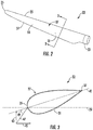
- the rotor blade 22 generally includes a blade root 24 configured for mounting the rotor blade 22 to the hub 20 of the wind turbine 10 ( FIG. 1 ) and a blade tip 23 disposed opposite the blade root 25.
- a body 27 of the rotor blade 22 may generally be configured to extend between the blade root 23 and the blade tip 25 and may serve as the outer casing/skin of the blade 22.
- the body 27 may define a substantially aerodynamic profile, such as by defining a symmetrical or cambered airfoil-shaped cross-section.
- the body 27 may include a pressure side 31 and a suction side 33 extending between a leading edge 35 and a trailing edge 37.
- a generator 24 may be disposed within the nacelle 16.
- the generator 24 may be coupled to the rotor 18 of the wind turbine 10 for generating electrical power from the rotational energy generated by the rotor 18.
- the rotor 18 may include a main shaft 40 coupled to the hub 20 for rotation therewith.
- the generator 24 may then be coupled to the main shaft 40 such that rotation of the main shaft 40 drives the generator 24.
- the generator 24 includes a generator shaft 42 rotatably coupled to the main shaft 40 through a gearbox 44.
- the generator shaft 42 may be rotatably coupled directly to the main shaft 40.
- the generator 24 may be directly rotatably coupled to the main shaft 40.
- the main shaft 40 may generally be supported within the nacelle 16 by a support frame or bedplate 46 positioned atop the wind turbine tower 12.
- the main shaft 40 may be supported by the bedplate 46 via a pair of pillow blocks 48, 50 mounted to the bedplate 46.
- the wind turbine 10 may also include a turbine control system or a turbine controller 26 within the nacelle 16.
- the turbine controller 26 is disposed within a control cabinet 52 mounted to a portion of the nacelle 16.
- the turbine controller 26 may be disposed at any location on or in the wind turbine 10, at any location on the support surface 14 or generally at any other location.
- the turbine controller 26 may generally be configured to control the various operating modes (e.g., start-up or shut-down sequences) and/or components of the wind turbine 10.
- the turbine controller 26 may also be communicatively coupled to various components of the wind turbine 10 for generally controlling the wind turbine 10 and/or such components.
- the turbine controller 26 may be communicatively coupled to the yaw drive mechanism(s) 38 of the wind turbine 10 for controlling and/or altering the yaw direction of the nacelle 16 relative to the direction 28 ( FIG. 1 ) of the wind.
- the turbine controller 26 may be configured to control a yaw angle of the nacelle 16 about a yaw axis 36 to position the rotor blades 22 with respect to the direction 28 of the wind, thereby controlling the loads acting on the wind turbine 10.
- the turbine controller 26 maybe configured to transmit control signals/commands to a yaw drive mechanism 38 ( FIG. 2 ) of the wind turbine 10, via a yaw controller or direct transmission, such that the nacelle 16 may be rotated about the yaw axis 36 via a yaw bearing 56.
- the turbine controller 26 may also be communicatively coupled to each pitch adjustment mechanism 32 of the wind turbine 10 (one of which is shown) through the pitch controller 30 for controlling and/or altering the pitch angle of the rotor blades 22 (i.e., an angle that determines a perspective of the rotor blades 22 with respect to the direction 28 of the wind).
- the turbine controller 26 and/or the pitch controller 30 may be configured to transmit a control signal/command to each pitch adjustment mechanism 32 such that one or more actuators (not shown) of the pitch adjustment mechanism 32 may be utilized to adjust the pitch angle of the rotor blades 22 by rotating the blades 22 along their pitch axes 34 via a pitch bearing 54.
- the turbine controller 26 may control the pitch angle of the rotor blades 22, either individually or simultaneously, by transmitting suitable control signals/commands to a pitch controller of the wind turbine 10, which may be configured to control the operation of a plurality of pitch drives or pitch adjustment mechanisms 32 ( FIG. 2 ) of the wind turbine, or by directly controlling the operation of the plurality of pitch drives or pitch adjustment mechanisms.
- one or more sensors 57, 58 may be provided on the wind turbine 10 for monitoring one or more conditions thereof. More specifically, as shown, the sensor(s) 57, 58 may be mounted at any suitable location for monitoring, e.g. a wind condition at or near the wind turbine 10.
- the illustrated wind turbine 10 includes a sensor 57 mounted to one or more of the rotor blades 22 and a wind sensor 58 mounted to the nacelle 16 of the wind turbine 10.
- the wind sensor 58 which may for example be a wind vane, an anemometer, a LIDAR sensor, and/or another suitable sensor, may measure wind speed and/or wind direction.
- such sensor(s) 57, 58 may be configured to monitor the wind conditions in real-time. Further, the sensors 57, 58 may be in communication with the controller 26, and may provide related information to the controller 26. For example, yawing of the wind turbine 10 may occur due to sensing of changes in the wind speed and/or wind direction 28.
- the term "monitor" and variations thereof indicates that the various sensors of the wind turbine 10 may be configured to provide a direct measurement of the parameters being monitored or an indirect measurement of such parameters.
- the sensors described herein may, for example, be used to generate signals relating to the parameter being monitored, which can then be utilized by the controller 26 to determine the condition.
- the controller 26 may be configured to determine an average wind speed based on a certain defined time period, e.g. 5 seconds, 10 seconds, 30 seconds, or any other suitable time period. Further, the controller 26 may similarly determine an average pitch angle based on a certain time period. Such values may also be filtered before the average is determined.
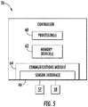
- the controller 26 may include one or more processor(s) 60 and associated memory device(s) 62 configured to perform a variety of computer-implemented functions (e.g., performing the methods, steps, calculations and the like and storing relevant data as disclosed herein). Additionally, the controller 26 may also include a communications module 64 to facilitate communications between the controller 26 and the various components of the wind turbine 10.
- the communications module 64 may include a sensor interface 66 (e.g., one or more analog-to-digital converters) to permit signals transmitted from the sensor(s) 57, 58 to be converted into signals that can be understood and processed by the processors 60.
- the sensor(s) 57, 58 may be communicatively coupled to the communications module 64 using any suitable means.
- the sensor(s) 57, 58 are coupled to the sensor interface 66 via a wired connection.
- the sensor(s) 57, 58 may be coupled to the sensor interface 66 via a wireless connection, such as by using any suitable wireless communications protocol known in the art.
- the term "processor” refers not only to integrated circuits referred to in the art as being included in a computer, but also refers to a controller, a microcontroller, a microcomputer, a programmable logic controller (PLC), an application specific integrated circuit, and other programmable circuits.
- the memory device(s) 62 may generally comprise memory element(s) including, but not limited to, computer readable medium (e.g., random access memory (RAM)), computer readable non-volatile medium (e.g., a flash memory), a floppy disk, a compact disc-read only memory (CD-ROM), a magneto-optical disk (MOD), a digital versatile disc (DVD) and/or other suitable memory elements.
- RAM random access memory
- CD-ROM compact disc-read only memory
- MOD magneto-optical disk
- DVD digital versatile disc
- Such memory device(s) 62 may generally be configured to store suitable computer-readable instructions that, when implemented by the processor(s) 60, configure the controller 26 to perform various functions including, but not limited to, transmitting suitable control signals to implement corrective action(s) in response to a distance signal exceeding a predetermined threshold as described herein, as well as various other suitable computer-implemented functions.
- a wind turbine 10 such as the nacelle 16 thereof, may rotate about the yaw axis 36 as required.
- rotation about the yaw axis 36 may occur due to changes in the wind speed and/or wind direction 28, such that the rotor 18 is aligned with the nominal wind direction 28 (i.e. the wind direction 28 that allows the wind turbine 10 to operate at rated power).
- the wind turbine 10 may actively yaw away from the nominal wind direction 28 to decrease pitch, thereby reducing noise associated with excessive blade pitching, e.g. during high winds.
- the nacelle 16 may be actively yawed in a direction opposite of the pitch.
- the turbine controller 26 is configured to implement a control strategy when the wind speed and/or the pitch angle increases above a predetermined threshold so as to reduce noise of the wind turbine 10.
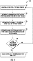
- the method 100 includes monitoring a wind speed at the wind turbine 10.
- the wind speed may be monitored via one or more of the sensors 57, 58.
- the controller 26 is further configured to determine a nominal wind direction for producing rated power of the wind turbine 10. As the wind speed rises above the cut-in speed, the level of electrical output power rises rapidly. However, typically somewhere between 12 and 17 meters per second, the power output reaches the limit that the electrical generator is capable of. This limit to the generator output is the rated power output. The wind speed at which the rated power is reached is the rated wind speed.
- the method 100 includes determining a pitch angle of at least one rotor blade 22 of the wind turbine 10. As shown at 108, the method 100 includes determining a yaw offset for the nacelle 16 of the wind turbine 10 based on the wind speed and/or the pitch angle. As used herein, the yaw offset generally refers to the angular difference between the nacelle orientation and the wind direction 28. As shown at 110, the method 100 is configured to determine whether the wind speed exceeds a predetermined threshold.
- the method 100 includes changing a yaw angle of the nacelle 16 by the yaw offset so as to reduce noise of the wind turbine 10.
- the turbine controller 26 is configured to actively yaw the nacelle 16 of the wind turbine 10 away from the nominal wind direction at high wind speeds to reduce noise created thereby.
- changing the yaw angle of the nacelle 16 by the yaw offset is configured to increase an angle of attack 49 ( FIG. 3 ) on the rotor blade 22.
- FIG. 3 non-limiting example of a snapshot of a cross-section of the rotor blade 22 rotating in a rotor plane 39 in the presence of wind 43 that is useful in understanding some technical features of the disclosed embodiments of the invention.
- the view is along the length of the blade 22 radially outwardly from the hub 20.
- a second component 45 of air flow is present (i.e. directed opposite to the movement of the section of the rotor blade 22), so that the apparent wind 47 is the vector sum of the wind 43 and the second component 45 of air flow.
- the apparent wind 47 direction relative to the chord line 41 of the blade 22 determines the angle of attack 49.
- the predetermined threshold may include wind speeds greater than a wind speed at which rated power occurs.
- the predetermined threshold may be any suitable wind speed that allows the wind turbine 10 to operate at rated power.
- this threshold may be any suitable pitch angle above the minimum pitch setting of the wind turbine 10.
- FIGS. 7 and 8 various graphs 120, 130 are provided to illustrate several benefits of the present disclosure.
- FIG. 7 illustrates a graph 120 of pitch angle/yaw offset and sound power (y-axes) versus hub height wind speed (x-axis) for conventional operation
- FIG. 8 illustrates a graph 130 of pitch angle/yaw offset and sound power (y-axes) versus hub height wind speed (x-axis) for the present disclosure.
- the yaw offset 126 is zero since the rotor 18 of the nacelle 16 is pointed directly into the wind during conventional operation.
- sound power 122 initially increases with rotor speed and then plateaus or decreases as shown between 125 and 127.
- wind speeds or pitch angles 124 exceed a certain threshold (e.g. as shown at 127)
- the pressure-side boundary layer of the rotor blade 22 thickens and/or flow separation can occur, which causes another increase in the sound power 122.
- FIG. 8 illustrates one example of operation of wind turbine 10 according to the present disclosure.
- the yaw offset 136 is changed as a function of the wind speed, such that pitch angle 134 and the sound power 132 remain constant.
- the controller 26 of the present disclosure increases (or decreases) the yaw offset 136 so as to reduce or maintain (i.e. not increase) the sound power 132 of the wind turbine 10.
- the yaw offset 136 may include any suitable angle, such as, e.g. 5 degrees, 10 degrees, 15 degrees, or 30 degrees.
- the yaw offset 136 may include angles greater than about sixteen (16) degrees.
- the yaw offset 136 may include angles less than 16 degrees.
- the term offset generally refers to an absolute value of an angle and can therefore include both positive and negative directions.
- the yaw offset 136 may not be able to be changed sufficiently to maintain constant blade pitch.
- the controller 26 is configured to pitch the rotor blades 22 above a certain wind speed, but at a reduced rate relative to conventional operation.
- such an operation provides a reduction in sound power 132 as compared to conventional operation ( FIG. 7 ).
- the controller 26 may increase the yaw offset 136 (or similarly decrease) at a particular wind speed 137, such that pitch angle 136 and the sound power 132 are reduced.
- the change in the yaw offset 136 may be defined in any number of ways, such as linear, polynomial, or comprised of a series of steps.
- the yaw offset 136 may be a predetermined yaw offset selected from a look-up table when the wind speed exceeds the predetermined threshold.
- the turbine controller 26 may be configured to calculate the yaw offset 136 as a function of the wind speed and/or the pitch angle when the wind speed exceeds the predetermined threshold.
- the turbine controller 26 may be configured to incrementally yaw the nacelle 16 away from the nominal wind direction 28 over a range of wind speeds. In other words, the change in the yaw angle may occur gradually. Alternatively, the turbine controller 26 may be configured to yaw the nacelle 16 away from the nominal wind direction 28 suddenly, i.e. in response to the wind speed exceeding the predetermined threshold.
- the method 200 includes monitoring a wind speed at or near the wind turbine 10, e.g. via one or more sensors 57, 58.
- the method 200 includes determining a nominal wind direction for producing rated power of the wind turbine 10.
- the method 200 includes determining a yaw offset for a nacelle of the wind turbine 10 based on, at least, the wind speed.
- the method 200 includes determining whether the wind speed exceeds a predetermined threshold.
- the method 200 includes changing a yaw angle of the nacelle 16 by the yaw offset so as to increase an angle of attack on the rotor blade 22.
- the increase of the angle of attack reduces noise from a pressure side surface of the rotor blade 22.
- the method 200 may further include determining a pitch angle of at least one rotor blade 22 of the wind turbine 10 and determining the yaw offset for the nacelle 16 of the wind turbine 10 based on the wind speed and/or the pitch angle.
Landscapes
- Engineering & Computer Science (AREA)
- Mechanical Engineering (AREA)
- Sustainable Development (AREA)
- Sustainable Energy (AREA)
- Chemical & Material Sciences (AREA)
- Combustion & Propulsion (AREA)
- Life Sciences & Earth Sciences (AREA)
- General Engineering & Computer Science (AREA)
- Human Computer Interaction (AREA)
- Manufacturing & Machinery (AREA)
- Physics & Mathematics (AREA)
- General Physics & Mathematics (AREA)
- Automation & Control Theory (AREA)
- Wind Motors (AREA)
Claims (14)
- Ein Verfahren (100) zum Reduzieren von Geräuschen einer Windturbine (10), wobei das Verfahren aufweisend ist:Bestimmen (102) einer Windgeschwindigkeit an der Windturbine (10);Bestimmen (104) einer nominalen Windrichtung zur Erzeugung von Nennleistung der Windturbine (10) mittels einer Steuerung (26);Bestimmen (106) eines Anstellwinkels von mindestens einem Rotorblatt (22) der Windturbine (10);Bestimmen (108) eines Azimut-Offsets für eine Gondel (16) der Windturbine (10) basierend auf der Windgeschwindigkeit und dem Anstellwinkel; undÄndern (112) eines Azimut-Winkels der Gondel (16) weg von der nominalen Windrichtung um den Azimut-Offset, wenn mindestens eines von der Windgeschwindigkeit oder dem Anstellwinkel einen vorbestimmten Schwellenwert überschreitet, um das Geräusch der Windturbine (10) zu reduzieren und um ein übermäßiges Nicken zu begrenzen und eine unerwünschte damit verbundene Geräuschzunahme zu vermeiden.
- Das Verfahren (100) nach Anspruch 1, das ferner aufweist: Ändern des Azimut-Winkels der Gondel (16) durch den Azimut-Offset, um einen Anstellwinkel am Rotorblatt zu vergrößern, wobei die Vergrößerung des Anstellwinkels Geräusche von einer Druckseitenfläche des Rotorblatts reduziert.
- Das Verfahren (100) nach einem der vorhergehenden Ansprüche, wobei das Bestimmen des Azimut-Offsets für die Gondel (16) der Windturbine basierend auf der Windgeschwindigkeit und dem Anstellwinkel ferner das Auswählen eines vorbestimmten Azimut-Offsets aus einer Look-Up-Tabelle aufweist, wenn die Windgeschwindigkeit den vorbestimmten Schwellenwert überschreitet.
- Das Verfahren (100) nach einem der vorhergehenden Ansprüche, wobei das Bestimmen des Azimut-Offsets für die Gondel (16) der Windturbine auf der Grundlage der Windgeschwindigkeit und des Anstellwinkels ferner das Berechnen des Azimut-Offsets als eine Funktion der Windgeschwindigkeit und des Anstellwinkels aufweist, wenn die Windgeschwindigkeit den vorbestimmten Schwellenwert überschreitet.
- Das Verfahren (100) nach einem der vorhergehenden Ansprüche weist ferner auf, dass die Gondel (16) über einen Bereich von Windgeschwindigkeiten schrittweise von der nominalen Windrichtung weg geschwenkt wird.
- Das Verfahren (100) nach einem der vorhergehenden Ansprüche weist ferner auf, dass die Windgeschwindigkeit an der Windturbine (10) in Echtzeit überwacht wird.
- Das Verfahren (100) nach einem der vorhergehenden Ansprüche, wobei der eine oder die mehreren Sensoren (57, 58) mindestens einen von einem Beschleunigungsmesser, einer Windfahne, einem Anemometer oder einem LIDAR-Sensor aufweisend sind.
- Das Verfahren (100) nach einem der vorhergehenden Ansprüche, wobei der vorbestimmte Schwellenwert mindestens eine der folgenden Angaben aufweist:
Windgeschwindigkeiten, die größer sind als eine Windgeschwindigkeit, bei der die Nennleistung erreicht wird, oder Anstellwinkel, die größer sind als eine minimale Anstelleinstellung der Windturbine. - Das Verfahren (100) nach einem der vorhergehenden Ansprüche, wobei der Azimut-Offset einen Winkel von mehr als etwa 16 Grad aufweist.
- Ein System zum Reduzieren von Geräuschen einer Windturbine (10), die durch übermäßiges Pitchen von mindestens einem Rotorblatt (22) verursacht werden, wobei das System aufweist:mindestens einen Sensor (57, 58), der zur Überwachung einer Windgeschwindigkeit an der Windturbine (10) konfiguriert ist;eine Steuerung (26), die kommunikativ mit dem mindestens einen Sensor verbunden ist, wobei die Steuerung mindestens einen Prozessor aufweist, der so konfiguriert ist, dass er eine oder mehrere Operationen durchführt, wobei die eine oder die mehreren Operationen Folgendes aufweisen:Bestimmen (104) einer nominalen Windrichtung zur Erzeugung einer Nennleistung der WindturbineBestimmen (106) eines Anstellwinkels von mindestens einem Rotorblatt (22) der Windturbine;Bestimmen (108) eines Azimut-Offsets für eine Gondel (16) der Windturbine (10), basierend auf mindestens der Windgeschwindigkeit und dem Anstellwinkel; undÄndern (112) eines Azimut-Winkels der Gondel (16) weg von der nominalen Windrichtung um den Azimut-Offset, wenn die Windgeschwindigkeit einen vorbestimmten Schwellenwert überschreitet, um ein übermäßiges Pitchen zu begrenzen und eine unerwünschte, damit verbundene Geräuschzunahme zu vermeiden, und um einen Anstellwinkel an dem Rotorblatt zu vergrößern,wobei die Vergrößerung des Anstellwinkels Geräusche von einer Druckseitenfläche des Rotorblatts reduziert.
- Das System nach Anspruch 10, wobei das Bestimmen des Azimut-Offsets für die Gondel (16) der Windturbine (10) basierend auf der Windgeschwindigkeit und dem Anstellwinkel ferner das Auswählen eines vorbestimmten Azimut-Offsets aus einer Look-Up-Tabelle aufweist, wenn die Windgeschwindigkeit den vorbestimmten Schwellenwert überschreitet.
- Das System nach einem der Ansprüche 10 bis 11, wobei das Bestimmen des Azimut-Offsets für die Gondel (16) der Windturbine (10) basierend auf der Windgeschwindigkeit und dem Anstellwinkel ferner das Berechnen des Azimut-Offsets als eine Funktion der Windgeschwindigkeit und des Anstellwinkels aufweist, wenn die Windgeschwindigkeit den vorbestimmten Schwellenwert überschreitet.
- Das System nach einem der Ansprüche 10 bis 12, ferner aufweisend ein schrittweises Schwenken der Gondel (16) weg von der nominalen Windrichtung über einen Bereich von Windgeschwindigkeiten.
- Das System nach einem der Ansprüche 10 bis 13, ferner aufweisend die Überwachung der Windgeschwindigkeit an der Windturbine (10) in Echtzeit.
Applications Claiming Priority (1)
| Application Number | Priority Date | Filing Date | Title |
|---|---|---|---|
| US15/618,180 US10451039B2 (en) | 2017-06-09 | 2017-06-09 | System and method for reducing wind turbine noise during high wind speed conditions |
Publications (2)
| Publication Number | Publication Date |
|---|---|
| EP3412909A1 EP3412909A1 (de) | 2018-12-12 |
| EP3412909B1 true EP3412909B1 (de) | 2021-05-05 |
Family
ID=62562999
Family Applications (1)
| Application Number | Title | Priority Date | Filing Date |
|---|---|---|---|
| EP18176306.1A Active EP3412909B1 (de) | 2017-06-09 | 2018-06-06 | System und verfahren zur verringerung von windturbinenlärm bei starkwindbedingungen |
Country Status (5)
| Country | Link |
|---|---|
| US (1) | US10451039B2 (de) |
| EP (1) | EP3412909B1 (de) |
| CA (1) | CA3007562A1 (de) |
| DK (1) | DK3412909T3 (de) |
| ES (1) | ES2884424T3 (de) |
Families Citing this family (11)
| Publication number | Priority date | Publication date | Assignee | Title |
|---|---|---|---|---|
| US20200263665A1 (en) * | 2019-02-14 | 2020-08-20 | General Electric Company | System and Method for Protecting Wind Turbines from Flutter During High Wind Speeds |
| US11261844B2 (en) * | 2019-02-28 | 2022-03-01 | General Electric Company | System and method for predicting wind turbine shutdowns due to excessive vibration |
| CN111749845B (zh) * | 2019-03-29 | 2022-04-05 | 北京金风科创风电设备有限公司 | 用于风电机组的降载控制方法和装置 |
| CN112855438B (zh) * | 2019-11-28 | 2023-03-28 | 北京国电思达科技有限公司 | 一种风电机组偏航对风动态补偿的方法 |
| WO2021209112A1 (en) * | 2020-04-16 | 2021-10-21 | Vestas Wind Systems A/S | Wind farm wake control activation method |
| CN111577542A (zh) * | 2020-05-09 | 2020-08-25 | 中国船舶重工集团海装风电股份有限公司 | 一种风电机组的噪音控制方法、装置、设备及介质 |
| CN112443461B (zh) * | 2020-10-10 | 2022-02-08 | 东北电力大学 | 基于对称声压传感器的风力发电机组偏航误差分析方法 |
| CN112505719B (zh) * | 2020-10-15 | 2024-08-30 | 中国科学院西安光学精密机械研究所 | 多普勒频率校正二次补偿的激光测风雷达测风方法及系统 |
| WO2022118327A1 (en) * | 2020-12-01 | 2022-06-09 | Sunit Tyagi | Apparatus and method for wind turbines operating in high winds and hurricanes |
| CN116838535B (zh) * | 2022-03-23 | 2024-12-10 | 江苏金风科技有限公司 | 风力发电机组的偏航控制方法及装置 |
| JP2024126410A (ja) * | 2023-03-07 | 2024-09-20 | 株式会社東芝 | 風力発電装置および風力発電装置の運転方法 |
Family Cites Families (24)
| Publication number | Priority date | Publication date | Assignee | Title |
|---|---|---|---|---|
| EP1744058A1 (de) * | 2004-05-07 | 2007-01-17 | Mitsubishi Denki Kabushiki Kaisha | Windkraftwerkbeurteilungssystem und vorhersagesteuerdienstsystem für windkraftwerk |
| US7387491B2 (en) | 2004-12-23 | 2008-06-17 | General Electric Company | Active flow modifications on wind turbine blades |
| NZ565921A (en) | 2005-07-15 | 2011-05-27 | Southwest Windpower Inc | Wind turbine and method of manufacture |
| US7476985B2 (en) | 2005-07-22 | 2009-01-13 | Gamesa Innovation & Technology, S.L. | Method of operating a wind turbine |
| US7883317B2 (en) | 2007-02-02 | 2011-02-08 | General Electric Company | Method for optimizing the operation of a wind turbine |
| US20090232635A1 (en) | 2008-03-12 | 2009-09-17 | General Electric Company | Independent sensing system for wind turbines |
| WO2010005289A2 (en) | 2008-07-11 | 2010-01-14 | Donqi Quandary Innovations Bv | Wind turbine with di ffuser |
| WO2010061255A2 (en) | 2008-11-01 | 2010-06-03 | Clipper Windpower, Inc. | Active blade pitch control for reduction of wind turbine noise or loads |
| US8427333B2 (en) | 2009-06-29 | 2013-04-23 | General Electric Company | System and method for detecting lightning |
| US8035241B2 (en) * | 2010-07-09 | 2011-10-11 | General Electric Company | Wind turbine, control system, and method for optimizing wind turbine power production |
| EP2489872B1 (de) | 2011-02-15 | 2013-03-20 | SSB Wind Systems GmbH & Co. KG | Schaufellastverringerung für Windrad |
| DK2686550T3 (en) | 2011-03-17 | 2016-10-24 | Vestas Wind Sys As | An apparatus for gaining access to the nacelle of a wind turbine and associated methods |
| EP2712402B1 (de) * | 2011-05-06 | 2020-12-23 | Seawind Ocean Technology Holding BV | Verfahren zur minimierung des für die leistungsabgabekontrolle erforderliche gierdrehmoments , für windenergieanlagen mit zwei taumelnd blättern |
| EP2565442A1 (de) | 2011-09-05 | 2013-03-06 | Siemens Aktiengesellschaft | System und Verfahren zum Betreiben einer Windturbine unter Verwendung anpassungsfähiger Bezugsvariabeln |
| CN103797244B (zh) | 2011-08-16 | 2017-09-12 | 维斯塔斯风力系统集团公司 | 用于风力涡轮机的声噪声监测系统 |
| DE102012222323A1 (de) | 2012-12-05 | 2014-06-05 | Wobben Properties Gmbh | Windenergieanlage sowie Verfahren zum Betreiben einer Windenergieanlage |
| US9562515B2 (en) | 2013-02-01 | 2017-02-07 | General Electric Company | Method and apparatus for wind turbine noise reduction |
| US9759068B2 (en) | 2013-02-28 | 2017-09-12 | General Electric Company | System and method for controlling a wind turbine based on identified surface conditions of the rotor blades |
| DK177928B1 (en) | 2013-06-17 | 2015-01-19 | Envision Energy Denmark Aps | Wind turbine blade with extended shell section |
| GB2515578A (en) | 2013-06-30 | 2014-12-31 | Wind Farm Analytics Ltd | Wind Turbine Nacelle Based Doppler Velocimetry Method and Apparatus |
| US10337496B2 (en) * | 2014-12-01 | 2019-07-02 | General Electric Company | System and method for controlling a wind turbine during adverse wind conditions |
| EP3073108B1 (de) | 2015-03-27 | 2019-10-02 | Siemens Gamesa Renewable Energy A/S | Steuerung für eine windturbine |
| US10024304B2 (en) | 2015-05-21 | 2018-07-17 | General Electric Company | System and methods for controlling noise propagation of wind turbines |
| WO2017035325A1 (en) | 2015-08-25 | 2017-03-02 | Nrg Systems Inc. | Techniques for determining yaw misalignment of a wind turbine and system and method using the same |
-
2017
- 2017-06-09 US US15/618,180 patent/US10451039B2/en active Active
-
2018
- 2018-06-06 ES ES18176306T patent/ES2884424T3/es active Active
- 2018-06-06 EP EP18176306.1A patent/EP3412909B1/de active Active
- 2018-06-06 DK DK18176306.1T patent/DK3412909T3/da active
- 2018-06-07 CA CA3007562A patent/CA3007562A1/en active Pending
Also Published As
| Publication number | Publication date |
|---|---|
| DK3412909T3 (da) | 2021-08-09 |
| US10451039B2 (en) | 2019-10-22 |
| CA3007562A1 (en) | 2018-12-09 |
| US20180355849A1 (en) | 2018-12-13 |
| EP3412909A1 (de) | 2018-12-12 |
| ES2884424T3 (es) | 2021-12-10 |
Similar Documents
| Publication | Publication Date | Title |
|---|---|---|
| US10451039B2 (en) | System and method for reducing wind turbine noise during high wind speed conditions | |
| EP3470669B1 (de) | Verfahren zur minderung von blattausreisserlasten bei einem neigungssystemausfall | |
| EP2860394B1 (de) | System und Verfahren zur Verhinderung von übermäßigem Laden auf einer Windturbine | |
| EP3067556B1 (de) | System und verfahren zur variablen steuerung des spitzen-drehzahl-verhältnisses einer windturbine | |
| EP2840258B1 (de) | System und Verfahren zur Vermeidung einer übermassige Belastung einer Windkraftenergieanlage | |
| US9551321B2 (en) | System and method for controlling a wind turbine | |
| EP3812578B1 (de) | System und verfahren zur steuerung einer windturbine auf basis eines kollektiven neigungsversatzes | |
| EP2910777B1 (de) | Dynamische einschaltwindgeschwindigkeit für windturbinen | |
| EP3812579B1 (de) | System und verfahren zur verbesserten extremlaststeuerung für windturbinenkomponenten | |
| EP3597904B1 (de) | System und verfahren zur reduzierung der belastungen von windturbinen durch gieren der gondel in eine vorbestimmte position basierend auf dem rotorungleichgewicht | |
| CN203297036U (zh) | 用于为风力涡轮的至少一个转子叶片确定桨距角的系统 | |
| EP3631200B1 (de) | System und verfahren zur optimierung der leistungsausgabe einer windenergieanlage bei eingeschränktem betrieb | |
| EP2981710B1 (de) | Verfahren zur steuerung der axiallast bei einer windturbine | |
| EP3470670B1 (de) | System und verfahren zum betreiben von windturbinen zur vermeidung von strömungsabrissen während der leistungsherabsetzung | |
| EP3029318B1 (de) | System und verfahren zur steuerung einer windturbine während ungünstiger windverhältnisse | |
| EP3964706B1 (de) | Verfahren zum betrieb einer windturbine sowie windturbine | |
| EP3892850B1 (de) | System und verfahren zur minderung der auf ein rotorblatt einer windturbine wirkenden lasten | |
| EP3643916B1 (de) | System und verfahren zur überwachung des schaufelblattzustands von windturbinen | |
| DK201570260A1 (en) | Over-speeding a rotor to maintain turbine output power |
Legal Events
| Date | Code | Title | Description |
|---|---|---|---|
| PUAI | Public reference made under article 153(3) epc to a published international application that has entered the european phase |
Free format text: ORIGINAL CODE: 0009012 |
|
| STAA | Information on the status of an ep patent application or granted ep patent |
Free format text: STATUS: THE APPLICATION HAS BEEN PUBLISHED |
|
| AK | Designated contracting states |
Kind code of ref document: A1 Designated state(s): AL AT BE BG CH CY CZ DE DK EE ES FI FR GB GR HR HU IE IS IT LI LT LU LV MC MK MT NL NO PL PT RO RS SE SI SK SM TR |
|
| AX | Request for extension of the european patent |
Extension state: BA ME |
|
| STAA | Information on the status of an ep patent application or granted ep patent |
Free format text: STATUS: REQUEST FOR EXAMINATION WAS MADE |
|
| 17P | Request for examination filed |
Effective date: 20190612 |
|
| RBV | Designated contracting states (corrected) |
Designated state(s): AL AT BE BG CH CY CZ DE DK EE ES FI FR GB GR HR HU IE IS IT LI LT LU LV MC MK MT NL NO PL PT RO RS SE SI SK SM TR |
|
| GRAP | Despatch of communication of intention to grant a patent |
Free format text: ORIGINAL CODE: EPIDOSNIGR1 |
|
| STAA | Information on the status of an ep patent application or granted ep patent |
Free format text: STATUS: GRANT OF PATENT IS INTENDED |
|
| INTG | Intention to grant announced |
Effective date: 20201126 |
|
| GRAS | Grant fee paid |
Free format text: ORIGINAL CODE: EPIDOSNIGR3 |
|
| GRAA | (expected) grant |
Free format text: ORIGINAL CODE: 0009210 |
|
| STAA | Information on the status of an ep patent application or granted ep patent |
Free format text: STATUS: THE PATENT HAS BEEN GRANTED |
|
| AK | Designated contracting states |
Kind code of ref document: B1 Designated state(s): AL AT BE BG CH CY CZ DE DK EE ES FI FR GB GR HR HU IE IS IT LI LT LU LV MC MK MT NL NO PL PT RO RS SE SI SK SM TR |
|
| REG | Reference to a national code |
Ref country code: GB Ref legal event code: FG4D |
|
| REG | Reference to a national code |
Ref country code: CH Ref legal event code: EP |
|
| REG | Reference to a national code |
Ref country code: AT Ref legal event code: REF Ref document number: 1390114 Country of ref document: AT Kind code of ref document: T Effective date: 20210515 |
|
| REG | Reference to a national code |
Ref country code: IE Ref legal event code: FG4D |
|
| REG | Reference to a national code |
Ref country code: DE Ref legal event code: R096 Ref document number: 602018016487 Country of ref document: DE |
|
| REG | Reference to a national code |
Ref country code: DK Ref legal event code: T3 Effective date: 20210803 |
|
| REG | Reference to a national code |
Ref country code: LT Ref legal event code: MG9D |
|
| REG | Reference to a national code |
Ref country code: AT Ref legal event code: MK05 Ref document number: 1390114 Country of ref document: AT Kind code of ref document: T Effective date: 20210505 |
|
| PG25 | Lapsed in a contracting state [announced via postgrant information from national office to epo] |
Ref country code: LT Free format text: LAPSE BECAUSE OF FAILURE TO SUBMIT A TRANSLATION OF THE DESCRIPTION OR TO PAY THE FEE WITHIN THE PRESCRIBED TIME-LIMIT Effective date: 20210505 Ref country code: HR Free format text: LAPSE BECAUSE OF FAILURE TO SUBMIT A TRANSLATION OF THE DESCRIPTION OR TO PAY THE FEE WITHIN THE PRESCRIBED TIME-LIMIT Effective date: 20210505 Ref country code: FI Free format text: LAPSE BECAUSE OF FAILURE TO SUBMIT A TRANSLATION OF THE DESCRIPTION OR TO PAY THE FEE WITHIN THE PRESCRIBED TIME-LIMIT Effective date: 20210505 Ref country code: BG Free format text: LAPSE BECAUSE OF FAILURE TO SUBMIT A TRANSLATION OF THE DESCRIPTION OR TO PAY THE FEE WITHIN THE PRESCRIBED TIME-LIMIT Effective date: 20210805 Ref country code: AT Free format text: LAPSE BECAUSE OF FAILURE TO SUBMIT A TRANSLATION OF THE DESCRIPTION OR TO PAY THE FEE WITHIN THE PRESCRIBED TIME-LIMIT Effective date: 20210505 |
|
| PG25 | Lapsed in a contracting state [announced via postgrant information from national office to epo] |
Ref country code: SE Free format text: LAPSE BECAUSE OF FAILURE TO SUBMIT A TRANSLATION OF THE DESCRIPTION OR TO PAY THE FEE WITHIN THE PRESCRIBED TIME-LIMIT Effective date: 20210505 Ref country code: RS Free format text: LAPSE BECAUSE OF FAILURE TO SUBMIT A TRANSLATION OF THE DESCRIPTION OR TO PAY THE FEE WITHIN THE PRESCRIBED TIME-LIMIT Effective date: 20210505 Ref country code: PT Free format text: LAPSE BECAUSE OF FAILURE TO SUBMIT A TRANSLATION OF THE DESCRIPTION OR TO PAY THE FEE WITHIN THE PRESCRIBED TIME-LIMIT Effective date: 20210906 Ref country code: LV Free format text: LAPSE BECAUSE OF FAILURE TO SUBMIT A TRANSLATION OF THE DESCRIPTION OR TO PAY THE FEE WITHIN THE PRESCRIBED TIME-LIMIT Effective date: 20210505 Ref country code: NO Free format text: LAPSE BECAUSE OF FAILURE TO SUBMIT A TRANSLATION OF THE DESCRIPTION OR TO PAY THE FEE WITHIN THE PRESCRIBED TIME-LIMIT Effective date: 20210805 Ref country code: PL Free format text: LAPSE BECAUSE OF FAILURE TO SUBMIT A TRANSLATION OF THE DESCRIPTION OR TO PAY THE FEE WITHIN THE PRESCRIBED TIME-LIMIT Effective date: 20210505 Ref country code: GR Free format text: LAPSE BECAUSE OF FAILURE TO SUBMIT A TRANSLATION OF THE DESCRIPTION OR TO PAY THE FEE WITHIN THE PRESCRIBED TIME-LIMIT Effective date: 20210806 Ref country code: IS Free format text: LAPSE BECAUSE OF FAILURE TO SUBMIT A TRANSLATION OF THE DESCRIPTION OR TO PAY THE FEE WITHIN THE PRESCRIBED TIME-LIMIT Effective date: 20210905 |
|
| REG | Reference to a national code |
Ref country code: ES Ref legal event code: FG2A Ref document number: 2884424 Country of ref document: ES Kind code of ref document: T3 Effective date: 20211210 |
|
| REG | Reference to a national code |
Ref country code: NL Ref legal event code: MP Effective date: 20210505 |
|
| PG25 | Lapsed in a contracting state [announced via postgrant information from national office to epo] |
Ref country code: NL Free format text: LAPSE BECAUSE OF FAILURE TO SUBMIT A TRANSLATION OF THE DESCRIPTION OR TO PAY THE FEE WITHIN THE PRESCRIBED TIME-LIMIT Effective date: 20210505 |
|
| PG25 | Lapsed in a contracting state [announced via postgrant information from national office to epo] |
Ref country code: RO Free format text: LAPSE BECAUSE OF FAILURE TO SUBMIT A TRANSLATION OF THE DESCRIPTION OR TO PAY THE FEE WITHIN THE PRESCRIBED TIME-LIMIT Effective date: 20210505 Ref country code: CZ Free format text: LAPSE BECAUSE OF FAILURE TO SUBMIT A TRANSLATION OF THE DESCRIPTION OR TO PAY THE FEE WITHIN THE PRESCRIBED TIME-LIMIT Effective date: 20210505 Ref country code: SM Free format text: LAPSE BECAUSE OF FAILURE TO SUBMIT A TRANSLATION OF THE DESCRIPTION OR TO PAY THE FEE WITHIN THE PRESCRIBED TIME-LIMIT Effective date: 20210505 Ref country code: SK Free format text: LAPSE BECAUSE OF FAILURE TO SUBMIT A TRANSLATION OF THE DESCRIPTION OR TO PAY THE FEE WITHIN THE PRESCRIBED TIME-LIMIT Effective date: 20210505 Ref country code: EE Free format text: LAPSE BECAUSE OF FAILURE TO SUBMIT A TRANSLATION OF THE DESCRIPTION OR TO PAY THE FEE WITHIN THE PRESCRIBED TIME-LIMIT Effective date: 20210505 |
|
| REG | Reference to a national code |
Ref country code: CH Ref legal event code: PL |
|
| REG | Reference to a national code |
Ref country code: DE Ref legal event code: R097 Ref document number: 602018016487 Country of ref document: DE |
|
| REG | Reference to a national code |
Ref country code: BE Ref legal event code: MM Effective date: 20210630 |
|
| PLBE | No opposition filed within time limit |
Free format text: ORIGINAL CODE: 0009261 |
|
| STAA | Information on the status of an ep patent application or granted ep patent |
Free format text: STATUS: NO OPPOSITION FILED WITHIN TIME LIMIT |
|
| PG25 | Lapsed in a contracting state [announced via postgrant information from national office to epo] |
Ref country code: MC Free format text: LAPSE BECAUSE OF FAILURE TO SUBMIT A TRANSLATION OF THE DESCRIPTION OR TO PAY THE FEE WITHIN THE PRESCRIBED TIME-LIMIT Effective date: 20210505 Ref country code: LU Free format text: LAPSE BECAUSE OF NON-PAYMENT OF DUE FEES Effective date: 20210606 |
|
| 26N | No opposition filed |
Effective date: 20220208 |
|
| PG25 | Lapsed in a contracting state [announced via postgrant information from national office to epo] |
Ref country code: LI Free format text: LAPSE BECAUSE OF NON-PAYMENT OF DUE FEES Effective date: 20210630 Ref country code: IE Free format text: LAPSE BECAUSE OF NON-PAYMENT OF DUE FEES Effective date: 20210606 Ref country code: CH Free format text: LAPSE BECAUSE OF NON-PAYMENT OF DUE FEES Effective date: 20210630 |
|
| PG25 | Lapsed in a contracting state [announced via postgrant information from national office to epo] |
Ref country code: IS Free format text: LAPSE BECAUSE OF FAILURE TO SUBMIT A TRANSLATION OF THE DESCRIPTION OR TO PAY THE FEE WITHIN THE PRESCRIBED TIME-LIMIT Effective date: 20210905 Ref country code: FR Free format text: LAPSE BECAUSE OF NON-PAYMENT OF DUE FEES Effective date: 20210705 Ref country code: AL Free format text: LAPSE BECAUSE OF FAILURE TO SUBMIT A TRANSLATION OF THE DESCRIPTION OR TO PAY THE FEE WITHIN THE PRESCRIBED TIME-LIMIT Effective date: 20210505 |
|
| PG25 | Lapsed in a contracting state [announced via postgrant information from national office to epo] |
Ref country code: IT Free format text: LAPSE BECAUSE OF FAILURE TO SUBMIT A TRANSLATION OF THE DESCRIPTION OR TO PAY THE FEE WITHIN THE PRESCRIBED TIME-LIMIT Effective date: 20210505 Ref country code: BE Free format text: LAPSE BECAUSE OF NON-PAYMENT OF DUE FEES Effective date: 20210630 |
|
| GBPC | Gb: european patent ceased through non-payment of renewal fee |
Effective date: 20220606 |
|
| PG25 | Lapsed in a contracting state [announced via postgrant information from national office to epo] |
Ref country code: GB Free format text: LAPSE BECAUSE OF NON-PAYMENT OF DUE FEES Effective date: 20220606 |
|
| PG25 | Lapsed in a contracting state [announced via postgrant information from national office to epo] |
Ref country code: CY Free format text: LAPSE BECAUSE OF FAILURE TO SUBMIT A TRANSLATION OF THE DESCRIPTION OR TO PAY THE FEE WITHIN THE PRESCRIBED TIME-LIMIT Effective date: 20210505 |
|
| P01 | Opt-out of the competence of the unified patent court (upc) registered |
Effective date: 20230530 |
|
| PG25 | Lapsed in a contracting state [announced via postgrant information from national office to epo] |
Ref country code: HU Free format text: LAPSE BECAUSE OF FAILURE TO SUBMIT A TRANSLATION OF THE DESCRIPTION OR TO PAY THE FEE WITHIN THE PRESCRIBED TIME-LIMIT; INVALID AB INITIO Effective date: 20180606 |
|
| REG | Reference to a national code |
Ref country code: DE Ref legal event code: R081 Ref document number: 602018016487 Country of ref document: DE Owner name: GENERAL ELECTRIC RENOVABLES ESPANA, S.L., ES Free format text: FORMER OWNER: GENERAL ELECTRIC COMPANY, SCHENECTADY, NY, US Ref country code: DE Ref legal event code: R082 Ref document number: 602018016487 Country of ref document: DE Ref country code: DE Ref legal event code: R082 Ref document number: 602018016487 Country of ref document: DE Representative=s name: ZIMMERMANN & PARTNER PATENTANWAELTE MBB, DE |
|
| REG | Reference to a national code |
Ref country code: DE Ref legal event code: R082 Ref document number: 602018016487 Country of ref document: DE Representative=s name: ZIMMERMANN & PARTNER PATENTANWAELTE MBB, DE |
|
| PG25 | Lapsed in a contracting state [announced via postgrant information from national office to epo] |
Ref country code: MK Free format text: LAPSE BECAUSE OF FAILURE TO SUBMIT A TRANSLATION OF THE DESCRIPTION OR TO PAY THE FEE WITHIN THE PRESCRIBED TIME-LIMIT Effective date: 20210505 |
|
| REG | Reference to a national code |
Ref country code: ES Ref legal event code: PC2A Owner name: GENERAL ELECTRIC RENOVABLES ESPANA S.L. Effective date: 20240809 |
|
| PG25 | Lapsed in a contracting state [announced via postgrant information from national office to epo] |
Ref country code: MT Free format text: LAPSE BECAUSE OF FAILURE TO SUBMIT A TRANSLATION OF THE DESCRIPTION OR TO PAY THE FEE WITHIN THE PRESCRIBED TIME-LIMIT Effective date: 20210505 |
|
| PGFP | Annual fee paid to national office [announced via postgrant information from national office to epo] |
Ref country code: DE Payment date: 20250520 Year of fee payment: 8 |
|
| PGFP | Annual fee paid to national office [announced via postgrant information from national office to epo] |
Ref country code: DK Payment date: 20250520 Year of fee payment: 8 |
|
| PGFP | Annual fee paid to national office [announced via postgrant information from national office to epo] |
Ref country code: ES Payment date: 20250701 Year of fee payment: 8 |
|
| PG25 | Lapsed in a contracting state [announced via postgrant information from national office to epo] |
Ref country code: TR Free format text: LAPSE BECAUSE OF FAILURE TO SUBMIT A TRANSLATION OF THE DESCRIPTION OR TO PAY THE FEE WITHIN THE PRESCRIBED TIME-LIMIT Effective date: 20210505 |