EP3412967A1 - Brûleur - Google Patents
Brûleur Download PDFInfo
- Publication number
- EP3412967A1 EP3412967A1 EP18176067.9A EP18176067A EP3412967A1 EP 3412967 A1 EP3412967 A1 EP 3412967A1 EP 18176067 A EP18176067 A EP 18176067A EP 3412967 A1 EP3412967 A1 EP 3412967A1
- Authority
- EP
- European Patent Office
- Prior art keywords
- burner
- diffuser
- frame
- metal sheet
- extension
- Prior art date
- Legal status (The legal status is an assumption and is not a legal conclusion. Google has not performed a legal analysis and makes no representation as to the accuracy of the status listed.)
- Withdrawn
Links
Images



Classifications
-
- F—MECHANICAL ENGINEERING; LIGHTING; HEATING; WEAPONS; BLASTING
- F23—COMBUSTION APPARATUS; COMBUSTION PROCESSES
- F23D—BURNERS
- F23D14/00—Burners for combustion of a gas, e.g. of a gas stored under pressure as a liquid
- F23D14/02—Premix gas burners, i.e. in which gaseous fuel is mixed with combustion air upstream of the combustion zone
-
- F—MECHANICAL ENGINEERING; LIGHTING; HEATING; WEAPONS; BLASTING
- F23—COMBUSTION APPARATUS; COMBUSTION PROCESSES
- F23D—BURNERS
- F23D14/00—Burners for combustion of a gas, e.g. of a gas stored under pressure as a liquid
- F23D14/12—Radiant burners
- F23D14/14—Radiant burners using screens or perforated plates
-
- F—MECHANICAL ENGINEERING; LIGHTING; HEATING; WEAPONS; BLASTING
- F23—COMBUSTION APPARATUS; COMBUSTION PROCESSES
- F23D—BURNERS
- F23D14/00—Burners for combustion of a gas, e.g. of a gas stored under pressure as a liquid
- F23D14/46—Details
-
- F—MECHANICAL ENGINEERING; LIGHTING; HEATING; WEAPONS; BLASTING
- F23—COMBUSTION APPARATUS; COMBUSTION PROCESSES
- F23D—BURNERS
- F23D14/00—Burners for combustion of a gas, e.g. of a gas stored under pressure as a liquid
- F23D14/46—Details
- F23D14/48—Nozzles
- F23D14/58—Nozzles characterised by the shape or arrangement of the outlet or outlets from the nozzle, e.g. of annular configuration
-
- F—MECHANICAL ENGINEERING; LIGHTING; HEATING; WEAPONS; BLASTING
- F23—COMBUSTION APPARATUS; COMBUSTION PROCESSES
- F23D—BURNERS
- F23D14/00—Burners for combustion of a gas, e.g. of a gas stored under pressure as a liquid
- F23D14/46—Details
- F23D14/70—Baffles or like flow-disturbing devices
-
- F—MECHANICAL ENGINEERING; LIGHTING; HEATING; WEAPONS; BLASTING
- F23—COMBUSTION APPARATUS; COMBUSTION PROCESSES
- F23D—BURNERS
- F23D14/00—Burners for combustion of a gas, e.g. of a gas stored under pressure as a liquid
- F23D14/46—Details
- F23D14/84—Flame spreading or otherwise shaping
-
- F—MECHANICAL ENGINEERING; LIGHTING; HEATING; WEAPONS; BLASTING
- F23—COMBUSTION APPARATUS; COMBUSTION PROCESSES
- F23D—BURNERS
- F23D2203/00—Gaseous fuel burners
- F23D2203/10—Flame diffusing means
- F23D2203/101—Flame diffusing means characterised by surface shape
- F23D2203/1012—Flame diffusing means characterised by surface shape tubular
-
- F—MECHANICAL ENGINEERING; LIGHTING; HEATING; WEAPONS; BLASTING
- F23—COMBUSTION APPARATUS; COMBUSTION PROCESSES
- F23D—BURNERS
- F23D2203/00—Gaseous fuel burners
- F23D2203/10—Flame diffusing means
- F23D2203/101—Flame diffusing means characterised by surface shape
- F23D2203/1017—Flame diffusing means characterised by surface shape curved
-
- F—MECHANICAL ENGINEERING; LIGHTING; HEATING; WEAPONS; BLASTING
- F23—COMBUSTION APPARATUS; COMBUSTION PROCESSES
- F23D—BURNERS
- F23D2203/00—Gaseous fuel burners
- F23D2203/10—Flame diffusing means
- F23D2203/102—Flame diffusing means using perforated plates
-
- F—MECHANICAL ENGINEERING; LIGHTING; HEATING; WEAPONS; BLASTING
- F23—COMBUSTION APPARATUS; COMBUSTION PROCESSES
- F23D—BURNERS
- F23D2203/00—Gaseous fuel burners
- F23D2203/10—Flame diffusing means
- F23D2203/102—Flame diffusing means using perforated plates
- F23D2203/1026—Flame diffusing means using perforated plates with slotshaped openings
Definitions
- the present invention relates to a burner for a combustion unit, e.g. in gas boilers.
- the combustion units of the known art comprise a combustion chamber with a heat exchanger, a burner connected to the combustion chamber for generating heat by means of the combustion of a combustible gas mixture and combustion air inside the combustion chamber, and also a supply duct for supplying the gas mixture and air to the burner.
- the burner comprises:
- the combustion surface and the frame are made in a single piece of high temperature resistant sheet metal perforated at the combustion surface and impervious at the frame.
- This solution is disadvantageous due to the formation of breaks caused by increased thermal gradients between very hot areas and relatively cold areas.
- a flexible porous layer on the perforated sheet for example a fabric or a metallic fiber mesh which serves both as combustion surface, which moves the combustion area away from the sheet, and as insulating material, which shields the sheet from the high temperatures of the gases in the combustion chamber, at the cost of needing to provide and assemble an additional and expensive component.
- the sheet metal diffusors are prone to buckling phenomena (sudden instability deformations from one modal shape to another modal shape of the diffuser) due to the increased rigidity of the sheet metal in its plane and to the impossibility of completely freely extending in accordance with the thermal stresses. This results in sudden mechanical stresses combined with thermal stresses which increase the risk of premature breaking of the diffuser.
- Mesh diffusers are easily deformable both in the extension plane and outside the extension plane and they do not have the aforesaid buckling problem.
- metal meshes for burners are very expensive, the porosity thereof is subjected to statistical variations which cannot be controlled with certainty, and the manufacturing of burners with metal mesh diffusers is more complex, slower and more expensive than manufacturing burners with perforated sheet diffusers.
- a gas burner which is suitable for a combustion unit of the type having a first housing part (combustion housing) that internally delimits a combustion space, a second housing part (gas supply housing) that internally delimits a gas supply space, a burner interposed between the first housing part and the second housing part, in which the burner comprises:
- the drawings show a gas burner 1 which is suitable for a combustion unit 10 of the type having a first housing part (combustion housing) 11 that internally delimits a combustion space 12, a second housing part (gas supply housing) 13 that internally delimits a gas supply space 14, and burner 1 interposed between the first housing part 11 and the second housing part 13.
- a combustion unit 10 of the type having a first housing part (combustion housing) 11 that internally delimits a combustion space 12, a second housing part (gas supply housing) 13 that internally delimits a gas supply space 14, and burner 1 interposed between the first housing part 11 and the second housing part 13.
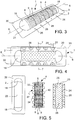
- Burner 1 comprises a frame 2 made of an impervious sheet metal having an outer peripheral portion 3 which can be connected to at least one of the first 11 and second 13 housing parts, a diffuser 4 made of perforated sheet metal, said diffuser 4 forming a combustion surface 5 surrounded by frame 2 and having an extension in a longitudinal direction 6 and an extension in a transverse direction 7, orthogonal to the longitudinal direction 6, in which the extension of the combustion surface 5 in the transverse direction 7 is smaller than the extension of the combustion surface 5 in the longitudinal direction 6, and in which the combustion surface 5 is intended to face the combustion space 12 so that a gas mixture conveyed through diffuser 4 may be combusted over the combustion surface 5 in the form of a flame scheme.
- diffuser 4 forms (at the combustion surface 5) a plurality of segments 8 of perforated sheet, mutually separated by means of through separation slits 9, and the through separation slits 9 extend in the transverse direction 7 for at least half of the extension of the combustion surface 5 in the transverse direction 7, preferably for at least three fourths of the extension of the combustion surface 5 in the transverse direction 7.
- the through separation slits 9 extend in the transverse direction 7 for substantially the whole extension of the combustion surface 5 in the transverse direction 7. This places the ends of the separation slits 9 in less hot areas of the burner and reduces thermal distortion, and the risk of formation of cracks at the ends of the separation slits 9.
- the combustion surface 5 may substantially be flat and the separation slits 9 may substantially be rectilinear and possibly parallel to one another.
- the combustion surface 5 may be the one of a shell curved towards the combustion side, advantageously a semi-cylinder or a cylinder portion, preferably with constant cross section (in a transverse plane orthogonal to the longitudinal direction 6), with the exception of the local interruptions due to the separation slits 9 and to the perforation.
- the separation slits 9 advantageously are rectilinear from a top view and in the shape of an arc of circle in cross section, as shown in figures 1 , 3 , 7 .
- the separation slits 9 advantageously are parallel to one another.
- the separation slits 9 have a width in the longitudinal direction 6 which is greater than 1/80 of the longitudinal length 15 of at least one of the adjacent segments 8 of perforated sheet (in particular, of the longest adjacent segment 8), but which is not greater than 1.5 mm. This reconciles the uncoupling need of the thermal deformations of the individual segments 8 with the need to make a perforated combustion surface 5 without excessive concentrations of pervious areas to avoid flashback phenomena and/or anomalous speed spikes of the gases.
- the perforation of diffuser 4 does not extend up to the separation slits 9 ( figure 10 ).
- the separation slits 9 ( figure 10 ) are delimited by transverse edges 17 of the segments 8 which are smooth or with continuous pattern. The smoothness of the transverse edges 17 obviates the occurrence of notching and the formation of cracks. An exception may be the formation of grooves or release holes formed at the ends of the separation slits 9, which will be described below.
- the segments 8 of perforated sheet advantageously have a length 15 in the longitudinal direction 6 which substantially is constant and/or substantially equal, in order to ensure properties of thermal capacity, temperature distribution, thermal and mechanical stresses, and also a perviousness distribution to the gas mixture, which are as uniform as possible and accordingly, to obtain operating properties of the burner which are as uniform, certain and predictable as possible.
- the segments 8 of perforated sheet advantageously have a length 15 in the longitudinal direction 6 which is less than a width 16 thereof in the transverse direction 7.
- the individual segments 8 of the combustion surface 5 are "locally” elongated in the transverse direction 7, while the whole combustion surface 5 is “globally” elongated in the longitudinal direction 6.
- the thermal expansions of the individual segments 8 in longitudinal direction 6 may not be added together due to the separation slits 9, and the thermal expansions of the individual segments 8 in transverse direction 7 may be absorbed due to a curvature outside the plane of frame 2.
- Such a curvature occurs systematically in the direction of the combustion space 12 due to the thermal flexure of diffuser 4 towards the hottest side thereof.
- burner 1 comprises two closing portions 18 of sheet metal extending outside the plane of frame 2 and closing otherwise free, longitudinal end spaces 19 between the combustion surface 5 and frame 2.
- diffuser 4 This allows the manufacturing of diffuser 4 to be simplified due to an easier forming of the perforated sheet by means of calendering or simple folding (around one longitudinal axis alone), for example in a press, and to simple portions of sheet "cap", preferably impervious, for closing burner 1 in the longitudinal end areas 19.
- a closure of the end portions required forming spherical metal mesh caps.
- the two closing portions 18 are of non-perforated sheet metal.
- the closing portions 18 may be shaped (for example, by means of a press) as part (e.g. one quarter) of a spherical cap to obtain a gradual transition between the plane of frame 2 and the upper area of the combustion surface 5.
- the closing portions 18 may be shaped as flat portions with or without stiffening ribs.
- the closing portions 18 have a double curvature cross section with a first rounded joining area between a flat portion of the frame and the closing portion 18, and with a second rounded joining area between the closing portion and the combustion surface, in which the second joining area has an offsetting curvature which is opposite to the curvature of the first joining area.
- burner 1 may comprise a distributor 23, preferably of perforated sheet with larger openings than the perforation openings of diffuser 4.
- Distributor 23 is arranged on the side of diffuser 4 opposite to the combustion side and may have a similar shape to the one of the combustion surface 5, for example a planar or curved shape or a shape of a portion of cylinder.
- distributor 23 may form a plurality of segments 8' of perforated sheet, mutually separated by means of through separation slits 9, and in which the through separation slits 9 extend in the transverse direction 7 for at least half or at least three quarters of the extension of distributor 23 in the transverse direction 7.
- the through separation slits 9' of distributor 23 extend in the transverse direction 7 for substantially the whole extension of distributor 23 in the transverse direction 7.
- the separation slits 9' may substantially be rectilinear and possibly parallel to one another.
- the separation slits 9' advantageously are rectilinear from a top view and in the shape of an arc of circle in cross section, as shown in figure 1 .
- the separation slits 9' advantageously are parallel to one another.
- the separation slits 9' of distributor 23 have a width in the longitudinal direction 6 which is greater than 1/80 of the longitudinal length 15' of at least one of the adjacent segments 8' of perforated sheet (in particular, of the longest adjacent segment 8'), but which is not greater than 1.5 mm.
- the perforation of distributor 23 does not extend up to the separation slits 9' ( figure 1 ).
- the separation slits 9' are delimited by edges of the segments 8' which are smooth or with continuous pattern.
- An exception may be the formation of grooves or release holes formed at the ends of the separation slits 9, which will be described below.
- the segments 8' of perforated sheet of distributor 23 advantageously have a substantially constant and/or substantially equal length 15' in the longitudinal direction 6.
- the segments 8' of perforated sheet of distributor 23 advantageously have a length 15' in the longitudinal direction 6 which is less than a width 16' thereof in the transverse direction 7.
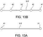
- one or both the ends of the separation slits 9, 9' of the diffuser or of the distributor may form rounded release holes or grooves which are widened with respect to the width of the separation slit 9, 9' ( figure 13a ).
- the separation slit(s) 9, 9' of the diffuser or of the distributor may form, along the extension thereof in transverse direction, a plurality of rounded holes or grooves which are widened with respect to the width of the separation slit 9, 9', and possibly arranged in an equally spaced manner. This facilitates the manufacturing and the shape accuracy of the separation slits.
- frame 2 comprises a front frame 20 of sheet metal forming a front opening 22, and a rear frame 24 of sheet metal different from the front frame 20 and forming one or more rear openings 25 overlapped with the front opening 22 of the front frame 20.
- Diffuser 4 is sandwiched and retained between the front 20 and rear 24 frames.
- the front 20 and rear 24 frames are connected to each other by mechanical fastening without welding, for example tox-clinching ( figures 3, 4 , 11 ), in a plurality of mutually spaced discrete connection positions 26.
- the sheet metal of the diffuser 4 extends at least partially around the connection positions 26 and has recesses 27 at the connection positions 26, so that the mechanical fastening without welding involves only the two sheet metals of the front 20 and rear 24 frames, but not also the metal sheet of the diffuser 4.
- the mechanical fastening without welding may be easily performed, e.g. the tox-clinching, on two sheet metals alone, thus obviating the difficulties of making mechanical fastenings without welding on more than two sheets.
- the diameter of the tox-clinching or of other airtight mechanical fastenings would be significantly larger. Carrying out the fastenings on two sheets alone saves precious space in order to increase the combustion surface and/or decrease the sizes of the frame, the overall volume of the burner being equal.
- the invention also allows carrying out the operations of mechanical fastening without welding in connection positions 26 which are distant from one another, and therefore which may be carried out simultaneously, with a saving of time and assembly cost of burner 1 which not only compensates for, rather exceeds the greater cost of material for the double sheet of frame 2.
- Mechanical fastenings without welding in particular include an airtight mechanical and/or shape connection (for example, by means of the aforesaid (tox-)clinching, non-through riveting, non-through stapling, screwing, stapling, nailing) in discrete points spaced apart from one another.
- diffuser 4 itself to have an extra level of freedom for accommodating thermal expansions.
- At least one of the front 20 and rear 24 frames forms reliefs 28 at the recesses 27 of the diffuser, said reliefs 28 having a shape which is at least partly complementary with the shape of the recesses 27 for an engagement thereof with certain mutual positioning ( figures 1 , 9, 10 ).
- the reliefs 28 may be bosses formed by pressing and having such a shape as to fill the corresponding recesses 27.
- the reliefs 28 have an outline complementary to the shape of the outline of the recesses 27.
- distance 29 (of the edge of recess 27) of the sheet metal of diffuser 4 from the connection position 26 is greater than three quarters of the diameter extension 30 or of the connection diameter (e.g. tox is 3 times less than the diameter extension 30 or the connection diameter, e.g. tox) ( figure 4 ).
- distance 29 (of the edge of recess 27) of the sheet metal of diffuser 4 from the connection position 26 is equal to or greater than the diameter extension 30 or the connection diameter (e.g. tox is 1.5 times less than the diameter extension 30 or the connection diameter, e.g. tox) ( figure 4 ).
- This facilitates the connection e.g., the tox-clinching of two sheet metals alone and at the same time allows a sufficient compacting and seal of the three overlapped sandwiched sheets.
- the reliefs 28 substantially are planar and delimited by a peripheral edge 31 thereof shaped as a step.
- the peripheral edge 31 of the reliefs 28, as well as the peripheral edge 32 of the recesses 27, preferably extends as an arc of circle around (and possibly concentric to) the connection position 26. This facilitates the positioning and centering of the pieces being pressed and carrying out the connection (for example, by means of tox-clinching) and allows an improved planarity and hold of the overlapped sandwiched sheets.
- the recesses 27 and also the reliefs 28 are "open" on an outer side thereof facing away from the combustion surface 5 ( figures 1 , 4 , 10 ), i.e. the peripheral edges 31, 32 thereof are interrupted by a cutting or by an outer side edge 34 of diffuser 4.
- the front frame 20 extends over the whole longitudinal length, laterally past the outer side edge 34 of diffuser 4 ( figure 4 ).
- connection positions 26 are arranged along two straight connection lines 33 parallel to the longitudinal direction 6 and arranged on two opposite sides of the combustion surface 5. At least three connection positions 26, preferably from 3 to 6, even more preferably 5 connection positions 26, are arranged along each connection line 33 ( figure 4 ).
- connection positions 26 positioned in sequence along a same connection line 33 preferably are equally spaced from one another.
- burner 1 is without connections outside the two connection lines 33 in order to reduce the mechanical stresses due to the prevention of thermal expansions at the connection positions 26.
- the front frame 20 and the rear frame 24 both are made of sheet metal having a lower resistance to high temperatures than the material of diffuser 4.
- the front frame 20 and the rear frame 24 are made of stainless steel sheet.
- Diffuser 4 may be made of high thermal resistance perforated sheet metal, for example ferritic stainless steel for high temperature.
- connection positions 26 between the front frame 20 and the rear frame 24 are formed in a same connection plane 35, at one or more flat portions of sheet 36 of the front frame 20 and of the rear frame 24 parallel to the connection plane 35.
- connection positions 26 in extending portions of sheet 36 tending to be planar allows using punches, presses and matrixes for making mechanical connections between the front frame 20 and the rear frame 24 in a quick and repeatable manner.
- connection position means "connection or connection point without spatial limitation to one point alone in the mathematical sense”.
- connection positions 26 are spaced apart from one another by at least 20 mm. This allows all the connections to be made simultaneously in a single step by means of a press or by means of a spot welder.
- the boundary line 37 is formed by an edge of the front frame 20 or, exceptionally and less preferably, of the rear frame 24, which extends uninterruptedly all around the combustion surface 5 and therefore, around the diffusion area.
- the outer peripheral portion 3 of frame 2 preferably is flat to facilitate a connection thereof which is impervious to housing 11, 13 of the combustion unit 10.
- the boundary line 37 extends in a single boundary plane which may be parallel or identical to the plane of the outer peripheral portion 3 of frame 2.
- the rear frame 24 forms a perforated sheet portion 38 which forms the aforesaid rear openings 25 in the shape of a perforation which serves the function of distributing the combustible gas mixture towards diffuser 4 in the desired manner.
- the perforated sheet portion 38 may have a shape which is complementary to the shape of the perforated portion of diffuser 4 and extending adjacent to or in direct contact therewith.
- the perforated sheet portion 38 may have a shape which is non-complementary to the shape of the perforated portion of diffuser 4.
- diffuser 4 forms a fold 39, extending along the boundary line 37, which forms a separation line between the combustion surface 5 and an outer edge 40 of diffuser 4, which is sandwiched between the front frame 20 and the rear frame 24.
- the front frame 20, diffuser 4 and the rear frame 24 are mutually connected to one another so as to form a preassembled, self-supporting frame-diffuser unit which may be transported, stored and mounted in the combustion unit 10 as a single piece.
- Burner 6 may be made by means of the following steps:
- the combustion unit 10 may be made by means of the following steps:
Landscapes
- Engineering & Computer Science (AREA)
- Chemical & Material Sciences (AREA)
- Combustion & Propulsion (AREA)
- Mechanical Engineering (AREA)
- General Engineering & Computer Science (AREA)
- Gas Burners (AREA)
Applications Claiming Priority (1)
| Application Number | Priority Date | Filing Date | Title |
|---|---|---|---|
| IT102017000062155A IT201700062155A1 (it) | 2017-06-07 | 2017-06-07 | Bruciatore |
Publications (1)
| Publication Number | Publication Date |
|---|---|
| EP3412967A1 true EP3412967A1 (fr) | 2018-12-12 |
Family
ID=60294148
Family Applications (1)
| Application Number | Title | Priority Date | Filing Date |
|---|---|---|---|
| EP18176067.9A Withdrawn EP3412967A1 (fr) | 2017-06-07 | 2018-06-05 | Brûleur |
Country Status (3)
| Country | Link |
|---|---|
| EP (1) | EP3412967A1 (fr) |
| CN (1) | CN109000251A (fr) |
| IT (1) | IT201700062155A1 (fr) |
Cited By (2)
| Publication number | Priority date | Publication date | Assignee | Title |
|---|---|---|---|---|
| EP3652484A1 (fr) * | 2017-07-13 | 2020-05-20 | Bekaert Combustion Technology B.V. | Brûleur à gaz à prémélange |
| EP4215814A1 (fr) | 2022-01-25 | 2023-07-26 | Beckett Thermal Solutions S.R.L. | Brûleur |
Citations (5)
| Publication number | Priority date | Publication date | Assignee | Title |
|---|---|---|---|---|
| NL8801383A (nl) * | 1988-05-30 | 1989-12-18 | Nefit Nv | Metalen branderdek. |
| US5649821A (en) * | 1994-07-08 | 1997-07-22 | Fogliani; Giuseppe | Gas burner with an improved diffuser |
| EP1030107A1 (fr) * | 1999-02-18 | 2000-08-23 | Worgas Bruciatori S.R.L. | Brûleur à prémélange gazeux |
| EP2102551A2 (fr) * | 2006-12-22 | 2009-09-23 | Worgas Bruciatori S.R.L. | Brûleur avec diffuseur résistant à des températures élevées de fonctionnement |
| US20160238243A1 (en) * | 2015-02-16 | 2016-08-18 | Worgas Bruciatori S.R.L. | Burner |
-
2017
- 2017-06-07 IT IT102017000062155A patent/IT201700062155A1/it unknown
-
2018
- 2018-06-05 EP EP18176067.9A patent/EP3412967A1/fr not_active Withdrawn
- 2018-06-07 CN CN201810582262.1A patent/CN109000251A/zh active Pending
Patent Citations (5)
| Publication number | Priority date | Publication date | Assignee | Title |
|---|---|---|---|---|
| NL8801383A (nl) * | 1988-05-30 | 1989-12-18 | Nefit Nv | Metalen branderdek. |
| US5649821A (en) * | 1994-07-08 | 1997-07-22 | Fogliani; Giuseppe | Gas burner with an improved diffuser |
| EP1030107A1 (fr) * | 1999-02-18 | 2000-08-23 | Worgas Bruciatori S.R.L. | Brûleur à prémélange gazeux |
| EP2102551A2 (fr) * | 2006-12-22 | 2009-09-23 | Worgas Bruciatori S.R.L. | Brûleur avec diffuseur résistant à des températures élevées de fonctionnement |
| US20160238243A1 (en) * | 2015-02-16 | 2016-08-18 | Worgas Bruciatori S.R.L. | Burner |
Cited By (2)
| Publication number | Priority date | Publication date | Assignee | Title |
|---|---|---|---|---|
| EP3652484A1 (fr) * | 2017-07-13 | 2020-05-20 | Bekaert Combustion Technology B.V. | Brûleur à gaz à prémélange |
| EP4215814A1 (fr) | 2022-01-25 | 2023-07-26 | Beckett Thermal Solutions S.R.L. | Brûleur |
Also Published As
| Publication number | Publication date |
|---|---|
| IT201700062155A1 (it) | 2018-12-07 |
| CN109000251A (zh) | 2018-12-14 |
Similar Documents
| Publication | Publication Date | Title |
|---|---|---|
| US20160238243A1 (en) | Burner | |
| JP6193984B2 (ja) | 表面燃焼ガスバーナ | |
| CN115127104A (zh) | 火排及其制造方法、燃烧器和热水器 | |
| EP3412967A1 (fr) | Brûleur | |
| EP2876369A1 (fr) | Brûleur à gaz | |
| TWI460379B (zh) | 燃燒加熱器 | |
| US20120244483A1 (en) | Flame hole unit structure of a gas burner | |
| EP3513122B1 (fr) | Brûleur de gaz pré-mélangé | |
| EP3412968A1 (fr) | Brûleur | |
| WO2017208107A1 (fr) | Brûleur | |
| ITMI20102181A1 (it) | Bruciatore ad elevata stabilita' | |
| EP2942564B1 (fr) | Brûleur à gaz | |
| EP4534904A1 (fr) | Brûleur à combustion totalement aéré | |
| EP4215814A1 (fr) | Brûleur | |
| ITMI20100791A1 (it) | Bruciatore a gas per caldaia | |
| EP1584868B1 (fr) | Brûleur cylindrique | |
| ITMI20060148A1 (it) | Dispositivo bruciatore ad elevata modulazione | |
| IT202000005191A1 (it) | Bruciatore | |
| US20170248306A1 (en) | Combination burner | |
| JP2025522027A (ja) | 予混合ガスバーナーおよび予混合ガスバーナーの製造方法 | |
| TWI802819B (zh) | 燃氣熱水器用燃燒器 | |
| KR200237131Y1 (ko) | 가스 보일러용 버너 | |
| JP6042837B2 (ja) | プレス仕上げ用鏝の製造方法 | |
| JP5146055B2 (ja) | 温風暖房機のルーバ構造 | |
| IT201700018574A1 (it) | Bruciatore |
Legal Events
| Date | Code | Title | Description |
|---|---|---|---|
| PUAI | Public reference made under article 153(3) epc to a published international application that has entered the european phase |
Free format text: ORIGINAL CODE: 0009012 |
|
| AK | Designated contracting states |
Kind code of ref document: A1 Designated state(s): AL AT BE BG CH CY CZ DE DK EE ES FI FR GB GR HR HU IE IS IT LI LT LU LV MC MK MT NL NO PL PT RO RS SE SI SK SM TR |
|
| AX | Request for extension of the european patent |
Extension state: BA ME |
|
| STAA | Information on the status of an ep patent application or granted ep patent |
Free format text: STATUS: THE APPLICATION IS DEEMED TO BE WITHDRAWN |
|
| 18D | Application deemed to be withdrawn |
Effective date: 20190613 |