EP3415213A1 - Élément filtrant, dispositif de pliage d'un support filtrant en forme de feuille continue et procédé de fabrication d'un élément filtrant plié en forme de zigzag - Google Patents
Élément filtrant, dispositif de pliage d'un support filtrant en forme de feuille continue et procédé de fabrication d'un élément filtrant plié en forme de zigzag Download PDFInfo
- Publication number
- EP3415213A1 EP3415213A1 EP18185865.5A EP18185865A EP3415213A1 EP 3415213 A1 EP3415213 A1 EP 3415213A1 EP 18185865 A EP18185865 A EP 18185865A EP 3415213 A1 EP3415213 A1 EP 3415213A1
- Authority
- EP
- European Patent Office
- Prior art keywords
- filter medium
- layers
- embossing
- web
- filter element
- Prior art date
- Legal status (The legal status is an assumption and is not a legal conclusion. Google has not performed a legal analysis and makes no representation as to the accuracy of the status listed.)
- Granted
Links
Images



Classifications
-
- B—PERFORMING OPERATIONS; TRANSPORTING
- B01—PHYSICAL OR CHEMICAL PROCESSES OR APPARATUS IN GENERAL
- B01D—SEPARATION
- B01D29/00—Filters with filtering elements stationary during filtration, e.g. pressure or suction filters, not covered by groups B01D24/00 - B01D27/00; Filtering elements therefor
- B01D29/01—Filters with filtering elements stationary during filtration, e.g. pressure or suction filters, not covered by groups B01D24/00 - B01D27/00; Filtering elements therefor with flat filtering elements
- B01D29/016—Filters with filtering elements stationary during filtration, e.g. pressure or suction filters, not covered by groups B01D24/00 - B01D27/00; Filtering elements therefor with flat filtering elements with corrugated, folded or wound filtering elements
-
- B—PERFORMING OPERATIONS; TRANSPORTING
- B01—PHYSICAL OR CHEMICAL PROCESSES OR APPARATUS IN GENERAL
- B01D—SEPARATION
- B01D29/00—Filters with filtering elements stationary during filtration, e.g. pressure or suction filters, not covered by groups B01D24/00 - B01D27/00; Filtering elements therefor
- B01D29/11—Filters with filtering elements stationary during filtration, e.g. pressure or suction filters, not covered by groups B01D24/00 - B01D27/00; Filtering elements therefor with bag, cage, hose, tube, sleeve or like filtering elements
- B01D29/111—Making filtering elements
-
- B—PERFORMING OPERATIONS; TRANSPORTING
- B01—PHYSICAL OR CHEMICAL PROCESSES OR APPARATUS IN GENERAL
- B01D—SEPARATION
- B01D29/00—Filters with filtering elements stationary during filtration, e.g. pressure or suction filters, not covered by groups B01D24/00 - B01D27/00; Filtering elements therefor
- B01D29/11—Filters with filtering elements stationary during filtration, e.g. pressure or suction filters, not covered by groups B01D24/00 - B01D27/00; Filtering elements therefor with bag, cage, hose, tube, sleeve or like filtering elements
- B01D29/13—Supported filter elements
- B01D29/15—Supported filter elements arranged for inward flow filtration
- B01D29/21—Supported filter elements arranged for inward flow filtration with corrugated, folded or wound sheets
-
- B—PERFORMING OPERATIONS; TRANSPORTING
- B01—PHYSICAL OR CHEMICAL PROCESSES OR APPARATUS IN GENERAL
- B01D—SEPARATION
- B01D46/00—Filters or filtering processes specially modified for separating dispersed particles from gases or vapours
- B01D46/52—Particle separators, e.g. dust precipitators, using filters embodying folded corrugated or wound sheet material
- B01D46/521—Particle separators, e.g. dust precipitators, using filters embodying folded corrugated or wound sheet material using folded, pleated material
-
- B—PERFORMING OPERATIONS; TRANSPORTING
- B01—PHYSICAL OR CHEMICAL PROCESSES OR APPARATUS IN GENERAL
- B01D—SEPARATION
- B01D46/00—Filters or filtering processes specially modified for separating dispersed particles from gases or vapours
- B01D46/52—Particle separators, e.g. dust precipitators, using filters embodying folded corrugated or wound sheet material
- B01D46/521—Particle separators, e.g. dust precipitators, using filters embodying folded corrugated or wound sheet material using folded, pleated material
- B01D46/523—Particle separators, e.g. dust precipitators, using filters embodying folded corrugated or wound sheet material using folded, pleated material with means for maintaining spacing between the pleats or folds
-
- B—PERFORMING OPERATIONS; TRANSPORTING
- B01—PHYSICAL OR CHEMICAL PROCESSES OR APPARATUS IN GENERAL
- B01D—SEPARATION
- B01D2201/00—Details relating to filtering apparatus
- B01D2201/12—Pleated filters
- B01D2201/127—Pleated filters with means for keeping the spacing between the pleats
Definitions
- the invention relates to a filter element, in particular an internal combustion engine, in particular of a motor vehicle with a filter medium from a media web, which consists of several layers and is folded along fold lines.
- the invention further relates to a device for folding a web-shaped filter medium of a filter element, in particular an internal combustion engine, in particular of a motor vehicle, with a feed device for the web-shaped filter medium, with an energy-carrying embossing unit, in particular an ultrasonic embossing unit, for embossing the web-shaped filter medium and with a folding device for folding of the web-shaped filter medium along crease lines.
- a device for folding a web-shaped filter medium of a filter element in particular an internal combustion engine, in particular of a motor vehicle
- a feed device for the web-shaped filter medium with an energy-carrying embossing unit, in particular an ultrasonic embossing unit, for embossing the web-shaped filter medium and with a folding device for folding of the web-shaped filter medium along crease lines.
- the invention relates to a method for producing a zigzag-folded filter element, in particular an internal combustion engine, in particular of a motor vehicle from a web-shaped filter medium, wherein the web-shaped filter medium via a feeder of an energy-carrying embossing unit, in particular an ultrasonic embossing unit is supplied, coined with the web-shaped filter medium is, and the filter medium is folded along fold lines by means of a folding device.
- an energy-carrying embossing unit in particular an ultrasonic embossing unit
- the filter element for removing particles from a fluid stream, in particular of particles from a fuel stream of an internal combustion engine, known.
- the filter element comprises an upper end plate, a lower end plate and an interposed, annular, star-shaped folded filter medium.
- a multilayer, web-shaped filter medium is used, which is folded into the filter element.
- the individual layers lie loosely on one another in the web-shaped filter medium.
- the filter medium is supplied by means of a feed device to a heat-carrying embossing unit, in particular an ultrasonic embossing unit, which imprints kink lines in the filter medium.
- the filter medium is then folded along the fold lines by means of a folding device.
- Layers of the multilayered filter medium are welded together by the embossing unit using the heat-carrying embossing unit during embossing.
- the invention has for its object to design a filter element, a device and a method of the type mentioned, with the / the layers of the web-shaped filter medium can be easily and precisely connected and folded together and the finished folded filter element even higher stability and filter efficiency having.
- the filter medium is embossed in at least one section between adjacent bend lines to form at least one further functional area and the layers of the multilayer filter medium are cohesively connected to one another along the embossing of the at least one functional area.
- the filter medium is embossed in at least one section to form at least one further functional area.
- the layers of the multilayer filter medium may be layers of different or the same materials.
- the layers of the filter medium along the embossments of the at least one further functional area are integrally connected to one another.
- the connection partners are held together by atomic or molecular forces.
- the cohesive connections are durable and robust against environmental influences. With the embossing and the additional cohesive connection, the stability of the filter medium is increased in the folded state.
- the functionality of the filter element in particular the filtration performance and / or the service life and / or the stability and / or a pressure difference between the clean side and the raw side of the filter medium, is improved by the combination of embossing and cohesive connection. Due to the fact that only in the area of the embossings cohesive connections and in other sections the layers of the filter medium can loosely lie against each other, a total area of the filter medium, which may be affected by embossing and connections with respect to a fluid flow, minimized. In this way, the surface of the filter medium becomes active for filtration optimized. Furthermore, advantageously, the embossing and the integral connection can be carried out in one process step, so that the manufacturing outlay can be reduced.
- embossing and cohesive connection furthermore makes it possible to combine a very wide variety of filter layers, in particular of different materials and / or different construction and / or different dimensions.
- two or more layers can be embossed and bonded together in a material-locking manner.
- the crease lines can be embossed and the layers of the multi-layered filter medium along the embossing materially connected to one another.
- embossing the fold lines wrinkles can be improved, in particular simplified and specified.
- the creases can be embossed without material connection. It can be advantageously realized a cohesive connection without embossing the fold lines.
- the at least one further functional area may be a spacing nub and / or stabilizing nub.
- the flat sections adjacent to the folded filter medium can be kept at a distance from each other. In this way it can be prevented that the sheet-like sections can directly abut each other, which would affect the flow through the filter medium.
- at least one spacer nub may be provided in each or every second section.
- a plurality of spacer knobs can advantageously be provided between two adjacent fold lines.
- corresponding spacer studs mirrored to a respective plane containing a crease line and perpendicular to the unfolded filter medium track may be configured.
- the mirrored spacer knobs can abut each other when the filter medium is folded. In this way, the spacing can be improved.
- the at least one spacer knob may have the shape of half a cylinder jacket.
- the at least one spacer nub the shape of a half cone sheath to have. This has the advantage that the spacing knot can compensate for the wedge shape of the folds when the filter medium is folded. The spacer knot can thus lie over its length on an opposite fold surface or an approximately opposite other spacer knobs.
- the axis of the cylinder jacket or the conical jacket can advantageously extend perpendicular to the fold lines.
- the at least one spacer nub may further stabilize the planar portion in which it is arranged.
- the layers of the multilayer filter medium can be laminated, calendered, welded, fused or glued along the at least one embossing. In this way, a simple cohesive connection between the layers can be realized.
- the filter medium can be folded in a zigzag shape.
- a zigzag-folded filter medium can be easily formed into a closed filter element, in particular a round filter element.
- a zigzag folded filter element can be easily formed into a flat filter element.
- At least one, preferably two, of the layers of the multilayer filter medium may be of synthetic material.
- Synthetic materials can simply be embossed by means of an energy-carrying embossing process and at the same time be bonded cohesively to one another or else to a different, even non-synthetic material. Synthetic materials can be robust. With them, long service lives can be realized. They can be easily manufactured and recycled.
- At least one of the layers of the multilayer filter medium may comprise a grid, preferably a plastic grid.
- Gratings increase the stability of the filter medium.
- Plastic can be easily heated with the energy-bearing embossing unit, embossed and materially connected to the remaining layers, in particular welded, are.
- At least one of the layers of the multilayer filter medium may advantageously have a meltblown layer.
- the meltblown layer can be achieved a very good filtration performance, which can increase the service life of the filter element.
- Meltblown layers can be simply shaped, embossed and materially bonded, in particular welded.
- the layers can be embossed by means of an energy-introducing process, in particular by means of ultrasound embossing, and connected to one another in a materially bonded manner.
- an energy-introducing process the embossing and the integral connection can be realized simultaneously.
- a prefilter layer and a fine filter layer may be joined to one another in the filter medium in the direction of flow, wherein a second support layer for receiving the longitudinal or transverse forces under tensile or compressive stress may be applied on the raw side of the prefilter layer can, wherein the two support layers may each have different average maximum tensile forces in the longitudinal or transverse direction.
- a longitudinal direction the direction is defined in which the particular web-shaped and preferably rectangular filter medium has its greatest length, in particular the feed direction in the production of the filter medium.
- transverse direction the direction is defined, which along the width of the filter medium, perpendicular to the longitudinal direction and along which the filter medium is preferably folded.
- the different strengths have the advantage that is compensated by these in the longitudinal and transverse direction of the difference in length of the outer layers to the neutral position in the middle with any deflections during lamination, Rollenschneide-, embossing and setup process and thus improves the processability or in certain media configurations is first made sure.
- the necessary for the connection of bellows and end plate of the filter element stiffness, which is required when welding the filter medium with a thermoplastic end plate or when immersing the filter medium in a viscous adhesive is advantageously achieved by means of the support layer for receiving the transverse forces.
- the support layers in corresponding embodiments can advantageously fulfill the function of a drainage to prevent the packaging of the filter medium.
- Another advantage of the support layers consists in the possibility of the wrinkles "on Block "to drive, since due to the adjacent supporting layers of the flow is ensured.
- F t denotes the mean value of the maximum tensile force in Newtons
- b 15 mm
- the length of the sample is at least 180 mm.
- At least 10 tensile tests are required to determine the maximum mean tensile force.
- the material characteristic value is the mean value of the maximum tensile force in Newtons F t specified. Since, according to standards, the width b of 15 mm is defined as a fixed test size, the width-related breaking strength can be calculated from this at any time.
- the width-related bending stiffness S determined according to DIN 53121 is used below.
- the standard provides for various measuring methods, preferably a rectangular sample with the width b is clamped along a width and loaded at a distance I from the clamping with a force F, resulting in a maximum deflection f as a shift of the force application point.
- the average maximum tensile force of the transverse forces receiving support layer of the filter medium in the longitudinal direction be greater than 10 N.
- the average maximum tensile force of the transverse forces receiving support layer of the filter medium in the transverse direction may be greater than 20 N.
- the average maximum tensile force of the longitudinal forces receiving support layer of the filter medium in the longitudinal direction be greater than 20 N.
- the average maximum tensile force of the longitudinal forces receiving support layer of the filter medium in the transverse direction be greater than 10 N.
- the width-related bending stiffness of the transverse forces receiving support layer of the filter medium in the longitudinal direction of greater than 0.1 N ⁇ mm, in particular greater than 0.15 N ⁇ mm, respectively.
- the width-related bending stiffness of the transverse forces receiving support layer of the filter medium in the transverse direction can be greater than 0.3 N ⁇ mm, in particular greater than 0.4 N ⁇ mm.
- the width-related bending stiffness of the longitudinal forces receiving support layer of the filter medium in the longitudinal direction of greater than 0.3 N ⁇ mm, more preferably greater than 0.45 N ⁇ mm, respectively.
- the width-related bending stiffness of the longitudinal forces receiving support layer of the filter medium in the transverse direction may be greater than 0.1 N ⁇ mm, more preferably greater than 0.15 N ⁇ mm.
- the support layers can each be designed in the form of a grid, which can have crossing threads, wherein the crossing threads can span a thread angle.
- the thread angle of the supporting layer of the filter medium responsible for absorbing the transverse forces can be in the range from 70 ° to 120 °, preferably in the range from 80 ° to 100 °, particularly preferably at 90 °.
- the pre-filter layer of the filter medium may be formed from a meltblown layer having a thickness in the range of 0.1 mm to 1 mm and a basis weight in the range of 10 g / m 2 to 200 g / m 2 .
- the thickness of the meltblown layer of the filter medium may be between 0.2 mm and 0.4 mm and the basis weight between 90 g / m 2 and 110 g / m 2 .
- the fiber diameter of the prefilter layer and / or the fine filter layer of the filter medium may be in the range of 0.1 .mu.m to 10 .mu.m.
- the pre-filter layer and / or the fine filter layer of the filter medium may be made of materials selected from the group consisting of polybutylene terephthalate (PBT) meltblown, polyamide (PA) meltblown, polypropylene (PP) meltblown, and polyethersulfone (PES) meltblown ,
- PBT polybutylene terephthalate
- PA polyamide
- PP polypropylene
- PES polyethersulfone
- the fine filter layer of the filter medium may be formed from a meltblown layer having a thickness in the range of 0.1 mm to 1.5 mm and a basis weight in the range of 10 g / m 2 to 200 g / m 2 .
- the thickness of the meltblown layer of the filter medium may be between 0.6 mm and 1.0 mm and the basis weight between 90 g / m 2 and 110 g / m 2 .
- the filter medium may additionally have a third filter layer.
- the third filter layer of the filter medium may be formed from a meltblown layer having a thickness in the range of 0.1 mm to 1 mm and a basis weight in the range of 10 g / m 2 to 100 g / m 2 .
- the thickness of the meltblown layer of the filter medium may be between 0.2 mm and 0.4 mm and the basis weight between 30 g / m 2 and 60 g / m 2 .
- the third filter layer of the filter medium may be made of materials selected from the group consisting of polybutylene terephthalate (PBT) meltblown, polyamide (PA) meltblown, polypropylene (PP) meltblown, and polyethersulfone (PES) meltblown.
- PBT polybutylene terephthalate
- PA polyamide
- PP polypropylene
- PES polyethersulfone
- the fiber diameter of the third filter layer of the filter medium may be in the range of 0.1 ⁇ m to 10 ⁇ m.
- the third filter layer may be formed as an absolute separator.
- the support layers and / or the fine filter layer and / or the pre-filter layer may consist of a combination selected from the group consisting of mesh spunbond, spunbond spunbond, spunbond filter layers and mesh filter layers.
- the spunbond may be a spunbonded nonwoven.
- the filter layers and / or fine filter layer and / or prefilter layer can consist of dry-laid nonwoven, in particular carded web, and / or of wet-laid nonwoven.
- a filter layer and / or fine filter layer and / or pre-filter layer may be made of materials selected from a group consisting of synthetic polymers, preferably polybutylene terephthalate (PBT), polyamide (PA), polyethersulfone (PES), polyethylene terephthalate (PET), and / or of natural polymers and / or mixtures thereof.
- synthetic polymers preferably polybutylene terephthalate (PBT), polyamide (PA), polyethersulfone (PES), polyethylene terephthalate (PET), and / or of natural polymers and / or mixtures thereof.
- the object is further achieved according to the invention with the device in that the energy-carrying embossing unit is designed for embossing and materially joining layers of the multilayer filter medium along at least one Functional area in at least a portion of the filter medium between adjacent crease lines.
- the energy-carrying embossing unit is designed so that it simultaneously embosses the filter medium and the layers there together materially joined, in particular welded.
- the filter medium is thus permanently laminated in a particularly robust manner against environmental influences along the at least one further functional region.
- the stability of the filter medium is increased in the folded state.
- the subsequent folding is facilitated and improved by the defined and stable connection of the layers.
- the layers are welded together such that the bond strength at the bond lines of the layers is at least as great as the material strength within the individual layers.
- the energy-carrying embossing unit can be designed for embossing the fold lines and / or cohesively connecting the layers of the multilayer filter medium along the fold lines. In this way, the folding can be further facilitated and improved.
- an ultrasonic embossing unit can be used as the energy-carrying embossing unit.
- the energy can alternatively also be introduced by means of a thermal calender, laser or other energy sources.
- layers of the multilayer filter medium are not connected to each other before embossing.
- the layers can be dispensed with.
- the layers lie as a separate layers until the embossing process relaxed flat against each other and are relatively displaced. Tensions between the layers that can occur during embossing and folding are easily compensated. As a result, the embossing process and the folding process are simplified.
- the energy-carrying embossing unit may be arranged downstream of a Aufstellech for zigzag folding of the web-shaped Filter medium.
- the filter medium can be folded with the erection unit directly after embossing and cohesive bonding, in particular welding.
- the layers can simply align with one another in order to reduce stresses, which further simplifies the folding process and increases the precision.
- the energy-carrying embossing unit can have an anvil roller with embossing webs, an ultrasonically driven sonotrode and an embossing stamp, which is formed at least in particular by the sonotrode.
- the web-shaped filter medium can be easily embossed and welded in one step in a continuous process.
- a particular driven nip roll can be arranged in front of and behind the anvil roll in the transport direction of the filter medium.
- the positions of the nip rolls relative to the anvil roll are changeable to adjust an entry angle and exit angle across the anvil roll.
- Powered Nippwalzen can also serve to transport the filter medium webs.
- the speed of the nip rollers can be adjusted.
- the nip rollers can be adapted in position and / or speed to the properties of the filter medium web, in particular material composition, layer thicknesses and / or dimensions, in order to enable optimal embossing and integral connection, in particular welding.
- the object is further achieved by laminating layers of the multilayer filter medium along at least one functional area in at least one section of the filter medium between adjacent fold lines with the energy-carrying embossing unit and integrally joining them during embossing.
- the buckling lines in the web-shaped filter medium can be additionally embossed with the energy-carrying embossing unit and / or the layers of the multilayer filter medium along the fold lines are materially connected.
- the filter medium by means of an anvil roll with embossing webs, an ultrasound-driven sonotrode and an embossing die, which is in particular formed by the sonotrode at least, coined and cohesively connected, in particular welded, are.
- the multilayer filter medium after embossing and cohesive bonding, in particular welding can be folded in a zigzag manner with a positioning unit.
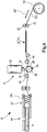
- FIG. 1 a device 10 for zigzag folding of a multilayer filter medium web 12 of a filter element 13 is shown.
- the filter element 13 is used for filtering liquid or gaseous fluids, for example engine oil, fuel, combustion air or compressed air, in motor vehicles.
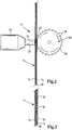
- the filter medium web 12 is, as in the FIGS. 2 and 3 shown, of three layers or layers, which initially lie loosely together.
- the two outer layers consist of plastic lattices 14. Between the plastic lattices 14, a meltblown layer 16 is arranged, which forms the middle layer.
- Alternative embodiments provide two or more layers.
- the endless filter medium web 12 is unrolled by a roller 18 in the conveying direction, indicated by an arrow 20, and passed between two transport rollers 22.
- the filter medium web 12, without being previously heated specifically, an ultrasonic embossing unit 24 is supplied.
- the ultrasonic embossing unit 24 has an anvil roller 26, which is peripherally equipped with a plurality of embossing bars 28.
- the embossing bars 28 are distributed at uniform intervals along the circumference of the anvil roller 26.
- the embossing bars 28 may also be distributed at irregular intervals along the circumference of the anvil roll 26. They each extend axially relative to the anvil roller 26, in the radial direction.
- the extent of the embossing webs 28 in the circumferential direction is in each case about 0.5 mm to 2 mm.
- the radially outer surfaces of the embossing bars 28 are smooth. Due to uneven distances of the embossing rods 28 changing fold heights can be realized.
- the ultrasonic embossing unit 24 has an ultrasound unit 30, with which ultrasound is introduced into a sonotrode 32 in a manner not of further interest here.
- the ultrasound unit 30 with the sonotrode 32 is located next to the anvil roller 26.
- the sonotrode 32 forms an embossing stamp, which cooperates with the embossing webs 28 of the anvil roller 26.
- the filter medium web 12 is moved between the anvil roll 26 and the sonotrode 32.
- the plastic grid 14 and the meltblown layer 16 can move relative to each other. In this way, mechanical stresses between the layers are reduced.
- the introduction of ultrasound at a tip 34 of the sonotrode 32 leads to heating of the filter medium web 12 in the areas defined by the embossing rods 28.
- the areas embossed in this way form creasing lines 36 for the subsequent folding of the filter medium web 12.
- the bending lines 36 are in the FIG. 3 in detail and in a finished filter element 13 in the FIGS. 4 and 5 shown.
- a flow direction of the fluid to be cleaned through the filter element 13 is in FIG. 5 indicated by arrows 41.
- the inflow side, ie the raw side of the filter element 13 is located in the FIG. 5 above.
- the downstream side, so the clean side of the filter element 13 is in FIG. 5 below.
- the heights of the embossing webs 28 in the radial direction, the distance between the tip 34 of the sonotrode 32 and the embossing webs 28 and the energy emitted by the sonotrode 32 onto the filter medium web 12 are based on the properties of the filter medium web 12, for example, the type of material, the layer thicknesses and the total thickness matched to simultaneously weld with the embossing process, the plastic mesh 14 and the meltblown layer 16 with the sonotrode 32 along the bending line 36 and so to connect materially.
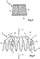
- FIG. 5 By way of example, only four of the spacer knobs 39 are shown. In reality, as in FIG. 8 shown, in each section 37 a plurality of spacer knobs 39 are arranged.
- FIG. 8 a section of the filter medium web 12 is shown in plan view.
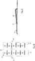
- FIG. 9 shows one of the spacing knobs 39 in section.
- the spacing knobs 39 in a section 37 are arranged next to one another in the transverse direction of the filter medium web 12, that is to say in the direction of the fold lines 36.
- the spacer nubs 39 each have the shape of half a cylinder jacket.
- the virtual axis of the cylinder jacket is approximately in the plane of the corresponding section 37. It extends transversely to the crease lines 36.
- the spacer knobs 39 are identical in shape and dimension. But it can also be provided 39 different spacer knobs.
- the course of the spacer knobs 39 can run at any angle between 0 ° and 135 ° to the crease lines 36, preferably in the range of 90 ° ⁇ 45 °.
- the spacer knobs 39 are each paired mirrored to the intermediate bending line 36 is arranged.
- the elevations of the mutually corresponding, mirrored spacing knobs 39 lie against one another and keep the fold surfaces at a distance from one another.
- the plastic grid 14 and the meltblown layer 16 are not connected to each other and can continue to align relative to each other.
- Mechanical stresses in the embossed and welded filter medium web 12 can be broken down more easily during the subsequent folding process, so that undesired wrinkling between the fold lines 36 is avoided and the folding process is simpler and more precise.
- the use of a single sonotrode 32 contributes to the avoidance of mechanical stresses and wrinkles in the filter medium web 12.
- the embossed and welded filter medium web 12 is fed via a deflection roller 38 and a deflection roller 40 at room temperature to an erection unit 42.
- the filter medium web 12 is folded in a zigzag fashion in a manner not of further interest here and cut into the filter elements 13.
- the filter elements 13 are then supplied to a not further interest folding pleat heater 44 and heated.
- FIG. 6 In a second embodiment, shown in FIG. 6 , are those elements that are those of the first, in the FIGS. 1 to 5 are similar to the described embodiment, provided with the same reference numerals, so that with respect to the description of the comments on the first embodiment reference is made.
- This embodiment differs from the first in that in the conveying direction 20 in front of and behind the anvil roll 26 in each case additionally a rotationally driven nip roll 46 is arranged, which serve to transport the filter medium web 12. On the pulleys 38 and 40 is omitted here.
- the nip rollers 46 are adjustable in their vertical position relative to the anvil roller 26, so that with them an entry angle and a discharge angle can be adjusted via the anvil roller 26.
- the positions and speeds of the nip rollers 46 are adjusted depending on the properties of the filter medium web 12 so that optimum embossing, welding and folding takes place. For some media, non-powered nip rolls may be advantageous.
- FIG. 7 a second embodiment of a filter element 13 is shown.
- the filter element 13 is configured in the second embodiment in the form of a round filter element.
- the filter medium web 12 from the FIGS. 1 to 3 . 8 and 9 here is annular, folded in a star shape and closed. At their end faces in each case a not interesting here end plate is arranged.
- a plurality of spacer studs 39 are arranged, of which in the FIG. 7 for the sake of clarity, only a few are shown.
- FIGS. 10 and 11 a second embodiment of a filter medium web 12 is shown, in which the spacer knobs 39 have the shape of a half-cone sheath.
- the tips of the cones of the spacer knobs 39 which are mirrored to a bend line 36 contained plane perpendicular to the filter medium web 12 and abut against each other when folded filter medium web 12, show each other.
- the mutually corresponding spacer knobs 39 abut each other over their axial length.
- a device 10 and a method for producing a zigzag folded filter element 13 the following modifications are possible, inter alia:
- the device 10 and the method are not limited to the production of zigzag folded filter medium webs 12 for filter elements 13 in the automotive field. Rather, they can also be used in other technical fields, for example in industrial filters for industrial engines or compressors or in water technology.
- the layers of the filter medium web 12 can also be embossed by means of a different energy-carrying process and bonded to one another in a material-locking manner. Instead of being welded together, the layers can also be connected to one another in a materially cohesive manner.
- the layers can also be laminated, calendered, fused or glued, for example.
- ultrasonic embossing unit 24 instead of the ultrasonic embossing unit 24 with a rotating anvil roll 26, a different type of ultrasonic embossing unit can also be used.
- a sonotrode traveling along with the filter medium web or a rotating sonotrode formed on a roll, for example an ultrasonic sonotrode roll, can be used.
- a filter medium web having more or less than three layers can also be embossed, cohesively bonded and folded with the device 10 according to the method.
- a composite of two grid layers and two meltblown layers can be used.
- filter medium web 12 with two plastic lattices 14 and a meltblown layer 16
- different types of multilayer filter medium webs for example of cellulose media with laminated meltblown, fleece with laminated lattices, glass fiber media, for example laminated glass fiber medium with lattice, or air filter fleece, can be cohesively bonded to the device 10, in particular, welded and folded.
- Filter media webs having at least one layer or layer of a synthetic material may be used. It may also be all layers or layers of the filter medium web of synthetic material.
- the two meltblown layers for example by means of polyurethane (PUR) hot melt adhesive in the spray application become.
- PUR polyurethane
- the two plastic lattices for example, also be laminated by means of PUR hot melt adhesive to the laminated meltblown layers.
- the two or more layers 14, 16 of the filter medium web 12 can also be unwound separately and only loosely placed against one another via corresponding transport rollers 22.
- corresponding spacer knobs 39 may be arranged only in each second section, which may abut directly on the folding surfaces of the respective other opposite sections 37 for spacing.
- the spacer knobs may also have different shape and / or orientation.
- the spacing knobs 39 can also be mutually elevated in a section 37, so that always every second spacing nub 39 is opposite in the inflow area and in the outflow area.
- spacing knobs 39 In addition or as an alternative to the spacing knobs 39, other types of functional areas, for example reinforcing webs, can also be embossed in the sections 37 between adjacent bend lines 36 and connected to one another in a material-locking manner.
- other types of functional areas for example reinforcing webs, can also be embossed in the sections 37 between adjacent bend lines 36 and connected to one another in a material-locking manner.
- the filter medium web 12 can also be heated, for example, by means of an inlet heating, for example for lamination of the individual layers, before it is fed to the ultrasonic embossing unit 24.
- stamping and / or cohesive bonding of the layers 14, 16 along the fold lines 36 can also be dispensed with in whole or in part.
- the extent of the embossing webs 28 in the circumferential direction of the anvil roller 26 may also be greater or less than 1 mm.
- the radially outer surfaces of the embossing bars 28 may be structured instead of smooth.
- non-driven nip rollers may be provided instead of the driven nip rollers 46. It can also be driven only one of the two Nippwalzen 46.
Landscapes
- Chemical & Material Sciences (AREA)
- Chemical Kinetics & Catalysis (AREA)
- Filtering Materials (AREA)
Priority Applications (1)
| Application Number | Priority Date | Filing Date | Title |
|---|---|---|---|
| PL18185865T PL3415213T3 (pl) | 2011-09-19 | 2012-08-17 | Element filtracyjny |
Applications Claiming Priority (3)
| Application Number | Priority Date | Filing Date | Title |
|---|---|---|---|
| DE102011113649A DE102011113649A1 (de) | 2011-09-19 | 2011-09-19 | Filterelement, Vorrichtung zum Falten eines bahnförmigen Filtermediums und Verfahren zur Herstellung eines zickzackförmig gefalteten Filterelements |
| PCT/EP2012/066068 WO2013041316A1 (fr) | 2011-09-19 | 2012-08-17 | Élément filtrant, dispositif pour plisser un médium filtrant en forme de bande et procédé pour fabriquer un élément filtrant plissé en accordéon |
| EP12748223.0A EP2758146B1 (fr) | 2011-09-19 | 2012-08-17 | Dispositif pour plisser un médium filtrant en forme de bande et procédé pour fabriquer un élément filtrant plissé en accordéon |
Related Parent Applications (1)
| Application Number | Title | Priority Date | Filing Date |
|---|---|---|---|
| EP12748223.0A Division EP2758146B1 (fr) | 2011-09-19 | 2012-08-17 | Dispositif pour plisser un médium filtrant en forme de bande et procédé pour fabriquer un élément filtrant plissé en accordéon |
Publications (2)
| Publication Number | Publication Date |
|---|---|
| EP3415213A1 true EP3415213A1 (fr) | 2018-12-19 |
| EP3415213B1 EP3415213B1 (fr) | 2020-12-23 |
Family
ID=46690520
Family Applications (2)
| Application Number | Title | Priority Date | Filing Date |
|---|---|---|---|
| EP12748223.0A Active EP2758146B1 (fr) | 2011-09-19 | 2012-08-17 | Dispositif pour plisser un médium filtrant en forme de bande et procédé pour fabriquer un élément filtrant plissé en accordéon |
| EP18185865.5A Active EP3415213B1 (fr) | 2011-09-19 | 2012-08-17 | Élément filtrant |
Family Applications Before (1)
| Application Number | Title | Priority Date | Filing Date |
|---|---|---|---|
| EP12748223.0A Active EP2758146B1 (fr) | 2011-09-19 | 2012-08-17 | Dispositif pour plisser un médium filtrant en forme de bande et procédé pour fabriquer un élément filtrant plissé en accordéon |
Country Status (7)
| Country | Link |
|---|---|
| US (1) | US9486719B2 (fr) |
| EP (2) | EP2758146B1 (fr) |
| CN (1) | CN103796726B (fr) |
| BR (1) | BR112014006391B1 (fr) |
| DE (1) | DE102011113649A1 (fr) |
| PL (2) | PL2758146T3 (fr) |
| WO (1) | WO2013041316A1 (fr) |
Families Citing this family (26)
| Publication number | Priority date | Publication date | Assignee | Title |
|---|---|---|---|---|
| DE102006014236A1 (de) | 2006-03-28 | 2007-10-04 | Irema-Filter Gmbh | Plissierbares Vliesmaterial und Verfahren und Vorrichtung zur Herstellung derselben |
| US8950587B2 (en) | 2009-04-03 | 2015-02-10 | Hollingsworth & Vose Company | Filter media suitable for hydraulic applications |
| DE102013008402B4 (de) | 2013-05-16 | 2025-07-17 | Irema-Filter Gmbh | Faservlies und Verfahren zur Herstellung desselben |
| EP3077078A1 (fr) | 2013-12-05 | 2016-10-12 | Mann+Hummel GmbH | Élément de filtrage avec soufflet de filtrage |
| FR3022153B1 (fr) * | 2014-06-12 | 2016-05-27 | Mecacorp | Procede et dispositif de fabrication d’un element filtrant pour filtre a air |
| DE102014014008A1 (de) * | 2014-09-25 | 2016-03-31 | Mann + Hummel Gmbh | Filterelement mit Filterbalg |
| DE102014117506A1 (de) * | 2014-11-28 | 2016-06-02 | Filta Co., Ltd | Filtermedium mit großem Faltenabstand |
| EP3777989B1 (fr) | 2015-08-17 | 2025-06-04 | Parker-Hannifin Corporation | Dispositifs de milieu de filtre, procédés de fabrication et presses de milieu de filtre |
| US11278833B2 (en) | 2015-08-17 | 2022-03-22 | Parker-Hamilton Corporation | Filter media packs, methods of making, and ultrasonic cutting or welding |
| KR102306389B1 (ko) * | 2016-03-08 | 2021-09-30 | 케이앤드엔 엔지니어링, 인크. | 초-주름형 차량 공기 필터 |
| CN105688514A (zh) * | 2016-03-21 | 2016-06-22 | 西安天厚滤清技术有限责任公司 | 用于油品过滤的聚酰胺滤材和滤芯 |
| JP6715653B2 (ja) * | 2016-04-01 | 2020-07-01 | 株式会社テクノフロンティア | 筒状フィルタ |
| JP6674823B2 (ja) * | 2016-04-01 | 2020-04-01 | 株式会社テクノフロンティア | 筒状フィルタ |
| CN109890666B (zh) * | 2016-10-20 | 2022-03-11 | 康明斯滤清系统知识产权公司 | 平坦的片的间断的定向凸起 |
| US11376541B2 (en) | 2016-12-15 | 2022-07-05 | Cummins Filtration Ip, Inc. | Tetrahedral filter media |
| JP6908901B2 (ja) * | 2017-01-26 | 2021-07-28 | 東洋精機株式会社 | 濾過シート材のひだ折り装置 |
| CN107158842A (zh) * | 2017-05-25 | 2017-09-15 | 江苏人和环保设备有限公司 | 一种具有滤材褶面凹陷部的空气滤芯 |
| FR3069455B1 (fr) * | 2017-07-28 | 2022-03-11 | Novares France | Procede de marquage d’une laize par utilisation d’ultrasons |
| JP7370695B2 (ja) * | 2018-10-17 | 2023-10-30 | 日本無機株式会社 | フィルタパック、及びエアフィルタ |
| DE102019200188A1 (de) * | 2019-01-09 | 2020-07-09 | Knorr-Bremse Systeme für Nutzfahrzeuge GmbH | Verfahren zum Verbinden eines Filtermaterials mit einem fluidtechnischen Bauteil und System aus einem fluidtechnischen Bauteil und einem damit verbindbaren Filtermaterial |
| EP3996830B1 (fr) * | 2019-08-26 | 2025-01-29 | Parker-Hannifin Corporation | Séparation améliorée d'eau de carburant à l'aide d'un gaufrage structurel |
| WO2021118524A1 (fr) | 2019-12-09 | 2021-06-17 | Cummins Filtration Inc. | Milieu filtrant façonné |
| CN112391879B (zh) * | 2020-11-17 | 2023-07-18 | 华东师范大学重庆研究院 | 一种激光诱导包覆石墨烯的导电型玻纤网制备方法和装置 |
| CN114602245A (zh) * | 2020-12-09 | 2022-06-10 | 3M创新有限公司 | 用于水过滤的层叠片材、圆筒状滤芯以及过滤套件 |
| EP4014935B1 (fr) * | 2020-12-18 | 2024-11-27 | Ontex BV | Procédé amélioré de fabrication d'un tampon |
| WO2024102211A1 (fr) | 2022-11-09 | 2024-05-16 | Baldwin Filters, Inc. | Épaisseur de milieu filtrant variable pour une performance d'écoulement et de filtre améliorée |
Citations (5)
| Publication number | Priority date | Publication date | Assignee | Title |
|---|---|---|---|---|
| EP0429805A2 (fr) * | 1989-11-27 | 1991-06-05 | Asf Air System Filter Ag | Procédé et dispositif pour la fabrication de pièces plissées à insérer dans un filtre |
| US5089202A (en) * | 1989-05-19 | 1992-02-18 | Lippold Hans Joachim | Method for the production of a filter cartridge |
| JPH0570607U (ja) * | 1992-03-03 | 1993-09-24 | 日本濾過器株式会社 | フィルタエレメント |
| DE19735993A1 (de) * | 1997-08-19 | 1999-02-25 | Mann & Hummel Filter | Filterelement, insbesondere zur Flüssigkeitsfilterung |
| US7625418B1 (en) * | 2005-06-08 | 2009-12-01 | Aaf-Mcquay, Inc. | Spacer arrangement for pleated filter |
Family Cites Families (6)
| Publication number | Priority date | Publication date | Assignee | Title |
|---|---|---|---|---|
| DE4433129A1 (de) | 1994-09-16 | 1996-03-28 | Gore W L & Ass Gmbh | Verfahren zur Herstellung eines Filtermediums |
| DE19920983C5 (de) * | 1999-05-06 | 2004-11-18 | Fibermark Gessner Gmbh & Co. Ohg | Zwei- oder mehrlagiges Filtermedium für die Luftfiltration und daraus hergestelltes Filterelement |
| US7661540B2 (en) * | 2003-12-30 | 2010-02-16 | Aaf Mcquay, Inc. | Method of forming spaced pleated filter material and product of same |
| DE502005007423D1 (de) * | 2004-03-31 | 2009-07-16 | Mann & Hummel Gmbh | Ansaugfilter für eine brennkraftmaschine eines fahrzeugs |
| DE202009003669U1 (de) | 2009-03-17 | 2010-08-12 | Mann+Hummel Gmbh | Filterelement |
| DE102010011785A1 (de) * | 2010-03-17 | 2011-09-22 | Mann+Hummel Gmbh | Vorrichtung zum Falten eines bahnförmigen Filtermediums und Verfahren zur Herstellung eines zickzackförmig gefalteten Filterelements |
-
2011
- 2011-09-19 DE DE102011113649A patent/DE102011113649A1/de not_active Ceased
-
2012
- 2012-08-17 PL PL12748223T patent/PL2758146T3/pl unknown
- 2012-08-17 PL PL18185865T patent/PL3415213T3/pl unknown
- 2012-08-17 CN CN201280045526.0A patent/CN103796726B/zh active Active
- 2012-08-17 EP EP12748223.0A patent/EP2758146B1/fr active Active
- 2012-08-17 EP EP18185865.5A patent/EP3415213B1/fr active Active
- 2012-08-17 BR BR112014006391-5A patent/BR112014006391B1/pt active IP Right Grant
- 2012-08-17 WO PCT/EP2012/066068 patent/WO2013041316A1/fr not_active Ceased
-
2014
- 2014-03-19 US US14/219,164 patent/US9486719B2/en active Active
Patent Citations (5)
| Publication number | Priority date | Publication date | Assignee | Title |
|---|---|---|---|---|
| US5089202A (en) * | 1989-05-19 | 1992-02-18 | Lippold Hans Joachim | Method for the production of a filter cartridge |
| EP0429805A2 (fr) * | 1989-11-27 | 1991-06-05 | Asf Air System Filter Ag | Procédé et dispositif pour la fabrication de pièces plissées à insérer dans un filtre |
| JPH0570607U (ja) * | 1992-03-03 | 1993-09-24 | 日本濾過器株式会社 | フィルタエレメント |
| DE19735993A1 (de) * | 1997-08-19 | 1999-02-25 | Mann & Hummel Filter | Filterelement, insbesondere zur Flüssigkeitsfilterung |
| US7625418B1 (en) * | 2005-06-08 | 2009-12-01 | Aaf-Mcquay, Inc. | Spacer arrangement for pleated filter |
Also Published As
| Publication number | Publication date |
|---|---|
| BR112014006391A2 (pt) | 2017-03-28 |
| PL3415213T3 (pl) | 2021-06-14 |
| CN103796726A (zh) | 2014-05-14 |
| EP3415213B1 (fr) | 2020-12-23 |
| US20140202123A1 (en) | 2014-07-24 |
| WO2013041316A1 (fr) | 2013-03-28 |
| EP2758146B1 (fr) | 2018-08-08 |
| DE102011113649A1 (de) | 2013-03-21 |
| PL2758146T3 (pl) | 2019-02-28 |
| EP2758146A1 (fr) | 2014-07-30 |
| CN103796726B (zh) | 2016-01-06 |
| BR112014006391B1 (pt) | 2020-11-10 |
| US9486719B2 (en) | 2016-11-08 |
Similar Documents
| Publication | Publication Date | Title |
|---|---|---|
| EP2758146B1 (fr) | Dispositif pour plisser un médium filtrant en forme de bande et procédé pour fabriquer un élément filtrant plissé en accordéon | |
| EP2547418B1 (fr) | Procédé de fabrication d'un élément filtrant plissé | |
| DE112010001186B4 (de) | Filtermedium, Verfahren zur Herstellung eines Filtermediums, und Filterelement | |
| EP0737091B9 (fr) | Cartouche de filtre et son procede de production | |
| WO1995017944A2 (fr) | Procede de fabrication d'une cartouche de filtre | |
| EP2806962B1 (fr) | Élément filtrant et procédé de fabrication d'un élément filtrant | |
| DE102009033587B4 (de) | Verstärktes Filterelement und Verfahren zum Verstärken eines Axialfilterkörpers | |
| EP1409106A1 (fr) | Procede de realisation d'une interface de connexion d'un element filtrant | |
| DE112014001189B4 (de) | Gewellte Filtermedien mit modulierten Wellen und Verfahren zur Herstellung | |
| EP2300125A1 (fr) | Bande filtrante multicouche | |
| DE102015013370A1 (de) | Filterelement, insbesondere für ein Kraftfahrzeug sowie Verfahren zum Herstellen eines Filterelements | |
| DE102008043334A1 (de) | Filter und Verfahren zu dessen Herstellung | |
| EP2512618B1 (fr) | Filtre compact, procédé de fabrication d'un filtre compact, et milieu filtrant | |
| EP2603302B1 (fr) | Procédé de fabrication d'une bande de matière filtrante | |
| WO2011160808A1 (fr) | Procédé de production d'un élément filtrant | |
| DE102018129345A1 (de) | Verfahren zum Herstellen eines Filterelements und Filterelement | |
| DE112015000874T5 (de) | Filtrationsmedien mit Flügeln und Verfahren zu deren Herstellung | |
| DE19647458B4 (de) | Flächengebilde aus zwei Außenlagen und einer klebenden Mittelschicht | |
| DE69930743T2 (de) | Faltenfilter und verfahren zur seiner herstellung | |
| WO2016046127A1 (fr) | Élément formant filtre pourvu d'un soufflet de filtre | |
| DE102020205247A1 (de) | Zickzack-gefaltetes vliesmaterial | |
| DE102011011771A1 (de) | Verfahren zum Herstellen eines Filterelements | |
| WO2019016228A1 (fr) | Matériau filtrant, paquet de plis, élément filtrant, procédé de fabrication d'un matériau filtrant et d'un paquet de plis, et procédé de filtration d'un fluide | |
| EP3124091A1 (fr) | Soufflet, element de filtre et procede | |
| EP1716905A1 (fr) | Dispositif de filtration |
Legal Events
| Date | Code | Title | Description |
|---|---|---|---|
| PUAI | Public reference made under article 153(3) epc to a published international application that has entered the european phase |
Free format text: ORIGINAL CODE: 0009012 |
|
| STAA | Information on the status of an ep patent application or granted ep patent |
Free format text: STATUS: THE APPLICATION HAS BEEN PUBLISHED |
|
| AC | Divisional application: reference to earlier application |
Ref document number: 2758146 Country of ref document: EP Kind code of ref document: P |
|
| AK | Designated contracting states |
Kind code of ref document: A1 Designated state(s): AL AT BE BG CH CY CZ DE DK EE ES FI FR GB GR HR HU IE IS IT LI LT LU LV MC MK MT NL NO PL PT RO RS SE SI SK SM TR |
|
| STAA | Information on the status of an ep patent application or granted ep patent |
Free format text: STATUS: REQUEST FOR EXAMINATION WAS MADE |
|
| 17P | Request for examination filed |
Effective date: 20190114 |
|
| RBV | Designated contracting states (corrected) |
Designated state(s): AL AT BE BG CH CY CZ DE DK EE ES FI FR GB GR HR HU IE IS IT LI LT LU LV MC MK MT NL NO PL PT RO RS SE SI SK SM TR |
|
| GRAP | Despatch of communication of intention to grant a patent |
Free format text: ORIGINAL CODE: EPIDOSNIGR1 |
|
| STAA | Information on the status of an ep patent application or granted ep patent |
Free format text: STATUS: GRANT OF PATENT IS INTENDED |
|
| INTG | Intention to grant announced |
Effective date: 20200311 |
|
| GRAJ | Information related to disapproval of communication of intention to grant by the applicant or resumption of examination proceedings by the epo deleted |
Free format text: ORIGINAL CODE: EPIDOSDIGR1 |
|
| STAA | Information on the status of an ep patent application or granted ep patent |
Free format text: STATUS: REQUEST FOR EXAMINATION WAS MADE |
|
| GRAP | Despatch of communication of intention to grant a patent |
Free format text: ORIGINAL CODE: EPIDOSNIGR1 |
|
| STAA | Information on the status of an ep patent application or granted ep patent |
Free format text: STATUS: GRANT OF PATENT IS INTENDED |
|
| INTC | Intention to grant announced (deleted) | ||
| INTG | Intention to grant announced |
Effective date: 20200805 |
|
| GRAS | Grant fee paid |
Free format text: ORIGINAL CODE: EPIDOSNIGR3 |
|
| GRAA | (expected) grant |
Free format text: ORIGINAL CODE: 0009210 |
|
| STAA | Information on the status of an ep patent application or granted ep patent |
Free format text: STATUS: THE PATENT HAS BEEN GRANTED |
|
| RIN1 | Information on inventor provided before grant (corrected) |
Inventor name: SCHOEN, MARIO Inventor name: WALZ, STEFAN |
|
| AC | Divisional application: reference to earlier application |
Ref document number: 2758146 Country of ref document: EP Kind code of ref document: P |
|
| AK | Designated contracting states |
Kind code of ref document: B1 Designated state(s): AL AT BE BG CH CY CZ DE DK EE ES FI FR GB GR HR HU IE IS IT LI LT LU LV MC MK MT NL NO PL PT RO RS SE SI SK SM TR |
|
| REG | Reference to a national code |
Ref country code: GB Ref legal event code: FG4D Free format text: NOT ENGLISH |
|
| REG | Reference to a national code |
Ref country code: DE Ref legal event code: R096 Ref document number: 502012016555 Country of ref document: DE |
|
| REG | Reference to a national code |
Ref country code: AT Ref legal event code: REF Ref document number: 1347175 Country of ref document: AT Kind code of ref document: T Effective date: 20210115 |
|
| REG | Reference to a national code |
Ref country code: IE Ref legal event code: FG4D Free format text: LANGUAGE OF EP DOCUMENT: GERMAN |
|
| PG25 | Lapsed in a contracting state [announced via postgrant information from national office to epo] |
Ref country code: RS Free format text: LAPSE BECAUSE OF FAILURE TO SUBMIT A TRANSLATION OF THE DESCRIPTION OR TO PAY THE FEE WITHIN THE PRESCRIBED TIME-LIMIT Effective date: 20201223 Ref country code: FI Free format text: LAPSE BECAUSE OF FAILURE TO SUBMIT A TRANSLATION OF THE DESCRIPTION OR TO PAY THE FEE WITHIN THE PRESCRIBED TIME-LIMIT Effective date: 20201223 Ref country code: GR Free format text: LAPSE BECAUSE OF FAILURE TO SUBMIT A TRANSLATION OF THE DESCRIPTION OR TO PAY THE FEE WITHIN THE PRESCRIBED TIME-LIMIT Effective date: 20210324 Ref country code: NO Free format text: LAPSE BECAUSE OF FAILURE TO SUBMIT A TRANSLATION OF THE DESCRIPTION OR TO PAY THE FEE WITHIN THE PRESCRIBED TIME-LIMIT Effective date: 20210323 |
|
| RAP4 | Party data changed (patent owner data changed or rights of a patent transferred) |
Owner name: MANN+HUMMEL GMBH |
|
| REG | Reference to a national code |
Ref country code: NL Ref legal event code: MP Effective date: 20201223 |
|
| PG25 | Lapsed in a contracting state [announced via postgrant information from national office to epo] |
Ref country code: BG Free format text: LAPSE BECAUSE OF FAILURE TO SUBMIT A TRANSLATION OF THE DESCRIPTION OR TO PAY THE FEE WITHIN THE PRESCRIBED TIME-LIMIT Effective date: 20210323 Ref country code: LV Free format text: LAPSE BECAUSE OF FAILURE TO SUBMIT A TRANSLATION OF THE DESCRIPTION OR TO PAY THE FEE WITHIN THE PRESCRIBED TIME-LIMIT Effective date: 20201223 Ref country code: SE Free format text: LAPSE BECAUSE OF FAILURE TO SUBMIT A TRANSLATION OF THE DESCRIPTION OR TO PAY THE FEE WITHIN THE PRESCRIBED TIME-LIMIT Effective date: 20201223 |
|
| PG25 | Lapsed in a contracting state [announced via postgrant information from national office to epo] |
Ref country code: HR Free format text: LAPSE BECAUSE OF FAILURE TO SUBMIT A TRANSLATION OF THE DESCRIPTION OR TO PAY THE FEE WITHIN THE PRESCRIBED TIME-LIMIT Effective date: 20201223 Ref country code: NL Free format text: LAPSE BECAUSE OF FAILURE TO SUBMIT A TRANSLATION OF THE DESCRIPTION OR TO PAY THE FEE WITHIN THE PRESCRIBED TIME-LIMIT Effective date: 20201223 |
|
| REG | Reference to a national code |
Ref country code: LT Ref legal event code: MG9D |
|
| PG25 | Lapsed in a contracting state [announced via postgrant information from national office to epo] |
Ref country code: SM Free format text: LAPSE BECAUSE OF FAILURE TO SUBMIT A TRANSLATION OF THE DESCRIPTION OR TO PAY THE FEE WITHIN THE PRESCRIBED TIME-LIMIT Effective date: 20201223 Ref country code: CZ Free format text: LAPSE BECAUSE OF FAILURE TO SUBMIT A TRANSLATION OF THE DESCRIPTION OR TO PAY THE FEE WITHIN THE PRESCRIBED TIME-LIMIT Effective date: 20201223 Ref country code: EE Free format text: LAPSE BECAUSE OF FAILURE TO SUBMIT A TRANSLATION OF THE DESCRIPTION OR TO PAY THE FEE WITHIN THE PRESCRIBED TIME-LIMIT Effective date: 20201223 Ref country code: PT Free format text: LAPSE BECAUSE OF FAILURE TO SUBMIT A TRANSLATION OF THE DESCRIPTION OR TO PAY THE FEE WITHIN THE PRESCRIBED TIME-LIMIT Effective date: 20210423 Ref country code: SK Free format text: LAPSE BECAUSE OF FAILURE TO SUBMIT A TRANSLATION OF THE DESCRIPTION OR TO PAY THE FEE WITHIN THE PRESCRIBED TIME-LIMIT Effective date: 20201223 Ref country code: RO Free format text: LAPSE BECAUSE OF FAILURE TO SUBMIT A TRANSLATION OF THE DESCRIPTION OR TO PAY THE FEE WITHIN THE PRESCRIBED TIME-LIMIT Effective date: 20201223 Ref country code: LT Free format text: LAPSE BECAUSE OF FAILURE TO SUBMIT A TRANSLATION OF THE DESCRIPTION OR TO PAY THE FEE WITHIN THE PRESCRIBED TIME-LIMIT Effective date: 20201223 |
|
| REG | Reference to a national code |
Ref country code: DE Ref legal event code: R097 Ref document number: 502012016555 Country of ref document: DE |
|
| PG25 | Lapsed in a contracting state [announced via postgrant information from national office to epo] |
Ref country code: IS Free format text: LAPSE BECAUSE OF FAILURE TO SUBMIT A TRANSLATION OF THE DESCRIPTION OR TO PAY THE FEE WITHIN THE PRESCRIBED TIME-LIMIT Effective date: 20210423 |
|
| PG25 | Lapsed in a contracting state [announced via postgrant information from national office to epo] |
Ref country code: AL Free format text: LAPSE BECAUSE OF FAILURE TO SUBMIT A TRANSLATION OF THE DESCRIPTION OR TO PAY THE FEE WITHIN THE PRESCRIBED TIME-LIMIT Effective date: 20201223 |
|
| PLBE | No opposition filed within time limit |
Free format text: ORIGINAL CODE: 0009261 |
|
| STAA | Information on the status of an ep patent application or granted ep patent |
Free format text: STATUS: NO OPPOSITION FILED WITHIN TIME LIMIT |
|
| PG25 | Lapsed in a contracting state [announced via postgrant information from national office to epo] |
Ref country code: DK Free format text: LAPSE BECAUSE OF FAILURE TO SUBMIT A TRANSLATION OF THE DESCRIPTION OR TO PAY THE FEE WITHIN THE PRESCRIBED TIME-LIMIT Effective date: 20201223 |
|
| 26N | No opposition filed |
Effective date: 20210924 |
|
| PG25 | Lapsed in a contracting state [announced via postgrant information from national office to epo] |
Ref country code: ES Free format text: LAPSE BECAUSE OF FAILURE TO SUBMIT A TRANSLATION OF THE DESCRIPTION OR TO PAY THE FEE WITHIN THE PRESCRIBED TIME-LIMIT Effective date: 20201223 |
|
| PG25 | Lapsed in a contracting state [announced via postgrant information from national office to epo] |
Ref country code: SI Free format text: LAPSE BECAUSE OF FAILURE TO SUBMIT A TRANSLATION OF THE DESCRIPTION OR TO PAY THE FEE WITHIN THE PRESCRIBED TIME-LIMIT Effective date: 20201223 |
|
| REG | Reference to a national code |
Ref country code: CH Ref legal event code: PL |
|
| PG25 | Lapsed in a contracting state [announced via postgrant information from national office to epo] |
Ref country code: MC Free format text: LAPSE BECAUSE OF FAILURE TO SUBMIT A TRANSLATION OF THE DESCRIPTION OR TO PAY THE FEE WITHIN THE PRESCRIBED TIME-LIMIT Effective date: 20201223 |
|
| REG | Reference to a national code |
Ref country code: BE Ref legal event code: MM Effective date: 20210831 |
|
| GBPC | Gb: european patent ceased through non-payment of renewal fee |
Effective date: 20210817 |
|
| PG25 | Lapsed in a contracting state [announced via postgrant information from national office to epo] |
Ref country code: LI Free format text: LAPSE BECAUSE OF NON-PAYMENT OF DUE FEES Effective date: 20210831 Ref country code: CH Free format text: LAPSE BECAUSE OF NON-PAYMENT OF DUE FEES Effective date: 20210831 |
|
| PG25 | Lapsed in a contracting state [announced via postgrant information from national office to epo] |
Ref country code: IS Free format text: LAPSE BECAUSE OF FAILURE TO SUBMIT A TRANSLATION OF THE DESCRIPTION OR TO PAY THE FEE WITHIN THE PRESCRIBED TIME-LIMIT Effective date: 20210423 Ref country code: LU Free format text: LAPSE BECAUSE OF NON-PAYMENT OF DUE FEES Effective date: 20210817 |
|
| PG25 | Lapsed in a contracting state [announced via postgrant information from national office to epo] |
Ref country code: IE Free format text: LAPSE BECAUSE OF NON-PAYMENT OF DUE FEES Effective date: 20210817 Ref country code: GB Free format text: LAPSE BECAUSE OF NON-PAYMENT OF DUE FEES Effective date: 20210817 Ref country code: BE Free format text: LAPSE BECAUSE OF NON-PAYMENT OF DUE FEES Effective date: 20210831 |
|
| REG | Reference to a national code |
Ref country code: AT Ref legal event code: MM01 Ref document number: 1347175 Country of ref document: AT Kind code of ref document: T Effective date: 20210817 |
|
| PG25 | Lapsed in a contracting state [announced via postgrant information from national office to epo] |
Ref country code: AT Free format text: LAPSE BECAUSE OF NON-PAYMENT OF DUE FEES Effective date: 20210817 |
|
| PG25 | Lapsed in a contracting state [announced via postgrant information from national office to epo] |
Ref country code: CY Free format text: LAPSE BECAUSE OF FAILURE TO SUBMIT A TRANSLATION OF THE DESCRIPTION OR TO PAY THE FEE WITHIN THE PRESCRIBED TIME-LIMIT Effective date: 20201223 |
|
| PG25 | Lapsed in a contracting state [announced via postgrant information from national office to epo] |
Ref country code: HU Free format text: LAPSE BECAUSE OF FAILURE TO SUBMIT A TRANSLATION OF THE DESCRIPTION OR TO PAY THE FEE WITHIN THE PRESCRIBED TIME-LIMIT; INVALID AB INITIO Effective date: 20120817 |
|
| PG25 | Lapsed in a contracting state [announced via postgrant information from national office to epo] |
Ref country code: MK Free format text: LAPSE BECAUSE OF FAILURE TO SUBMIT A TRANSLATION OF THE DESCRIPTION OR TO PAY THE FEE WITHIN THE PRESCRIBED TIME-LIMIT Effective date: 20201223 |
|
| PG25 | Lapsed in a contracting state [announced via postgrant information from national office to epo] |
Ref country code: TR Free format text: LAPSE BECAUSE OF FAILURE TO SUBMIT A TRANSLATION OF THE DESCRIPTION OR TO PAY THE FEE WITHIN THE PRESCRIBED TIME-LIMIT Effective date: 20201223 |
|
| PG25 | Lapsed in a contracting state [announced via postgrant information from national office to epo] |
Ref country code: MT Free format text: LAPSE BECAUSE OF FAILURE TO SUBMIT A TRANSLATION OF THE DESCRIPTION OR TO PAY THE FEE WITHIN THE PRESCRIBED TIME-LIMIT Effective date: 20201223 |
|
| PGFP | Annual fee paid to national office [announced via postgrant information from national office to epo] |
Ref country code: DE Payment date: 20250820 Year of fee payment: 14 |
|
| PGFP | Annual fee paid to national office [announced via postgrant information from national office to epo] |
Ref country code: IT Payment date: 20250825 Year of fee payment: 14 Ref country code: PL Payment date: 20250807 Year of fee payment: 14 |
|
| PGFP | Annual fee paid to national office [announced via postgrant information from national office to epo] |
Ref country code: FR Payment date: 20250828 Year of fee payment: 14 |