EP3415865A1 - Étalonnage de détecteur - Google Patents
Étalonnage de détecteur Download PDFInfo
- Publication number
- EP3415865A1 EP3415865A1 EP17175550.7A EP17175550A EP3415865A1 EP 3415865 A1 EP3415865 A1 EP 3415865A1 EP 17175550 A EP17175550 A EP 17175550A EP 3415865 A1 EP3415865 A1 EP 3415865A1
- Authority
- EP
- European Patent Office
- Prior art keywords
- pattern
- segments
- detector
- segment
- dark
- Prior art date
- Legal status (The legal status is an assumption and is not a legal conclusion. Google has not performed a legal analysis and makes no representation as to the accuracy of the status listed.)
- Ceased
Links
Images




Classifications
-
- G—PHYSICS
- G01—MEASURING; TESTING
- G01T—MEASUREMENT OF NUCLEAR OR X-RADIATION
- G01T7/00—Details of radiation-measuring instruments
- G01T7/005—Details of radiation-measuring instruments calibration techniques
-
- G—PHYSICS
- G01—MEASURING; TESTING
- G01D—MEASURING NOT SPECIALLY ADAPTED FOR A SPECIFIC VARIABLE; ARRANGEMENTS FOR MEASURING TWO OR MORE VARIABLES NOT COVERED IN A SINGLE OTHER SUBCLASS; TARIFF METERING APPARATUS; MEASURING OR TESTING NOT OTHERWISE PROVIDED FOR
- G01D5/00—Mechanical means for transferring the output of a sensing member; Means for converting the output of a sensing member to another variable where the form or nature of the sensing member does not constrain the means for converting; Transducers not specially adapted for a specific variable
- G01D5/26—Mechanical means for transferring the output of a sensing member; Means for converting the output of a sensing member to another variable where the form or nature of the sensing member does not constrain the means for converting; Transducers not specially adapted for a specific variable characterised by optical transfer means, i.e. using infrared, visible, or ultraviolet light
- G01D5/32—Mechanical means for transferring the output of a sensing member; Means for converting the output of a sensing member to another variable where the form or nature of the sensing member does not constrain the means for converting; Transducers not specially adapted for a specific variable characterised by optical transfer means, i.e. using infrared, visible, or ultraviolet light with attenuation or whole or partial obturation of beams of light
- G01D5/34—Mechanical means for transferring the output of a sensing member; Means for converting the output of a sensing member to another variable where the form or nature of the sensing member does not constrain the means for converting; Transducers not specially adapted for a specific variable characterised by optical transfer means, i.e. using infrared, visible, or ultraviolet light with attenuation or whole or partial obturation of beams of light the beams of light being detected by photocells
- G01D5/347—Mechanical means for transferring the output of a sensing member; Means for converting the output of a sensing member to another variable where the form or nature of the sensing member does not constrain the means for converting; Transducers not specially adapted for a specific variable characterised by optical transfer means, i.e. using infrared, visible, or ultraviolet light with attenuation or whole or partial obturation of beams of light the beams of light being detected by photocells using displacement encoding scales
- G01D5/34746—Linear encoders
-
- G—PHYSICS
- G01—MEASURING; TESTING
- G01D—MEASURING NOT SPECIALLY ADAPTED FOR A SPECIFIC VARIABLE; ARRANGEMENTS FOR MEASURING TWO OR MORE VARIABLES NOT COVERED IN A SINGLE OTHER SUBCLASS; TARIFF METERING APPARATUS; MEASURING OR TESTING NOT OTHERWISE PROVIDED FOR
- G01D5/00—Mechanical means for transferring the output of a sensing member; Means for converting the output of a sensing member to another variable where the form or nature of the sensing member does not constrain the means for converting; Transducers not specially adapted for a specific variable
- G01D5/26—Mechanical means for transferring the output of a sensing member; Means for converting the output of a sensing member to another variable where the form or nature of the sensing member does not constrain the means for converting; Transducers not specially adapted for a specific variable characterised by optical transfer means, i.e. using infrared, visible, or ultraviolet light
- G01D5/32—Mechanical means for transferring the output of a sensing member; Means for converting the output of a sensing member to another variable where the form or nature of the sensing member does not constrain the means for converting; Transducers not specially adapted for a specific variable characterised by optical transfer means, i.e. using infrared, visible, or ultraviolet light with attenuation or whole or partial obturation of beams of light
- G01D5/34—Mechanical means for transferring the output of a sensing member; Means for converting the output of a sensing member to another variable where the form or nature of the sensing member does not constrain the means for converting; Transducers not specially adapted for a specific variable characterised by optical transfer means, i.e. using infrared, visible, or ultraviolet light with attenuation or whole or partial obturation of beams of light the beams of light being detected by photocells
- G01D5/347—Mechanical means for transferring the output of a sensing member; Means for converting the output of a sensing member to another variable where the form or nature of the sensing member does not constrain the means for converting; Transducers not specially adapted for a specific variable characterised by optical transfer means, i.e. using infrared, visible, or ultraviolet light with attenuation or whole or partial obturation of beams of light the beams of light being detected by photocells using displacement encoding scales
- G01D5/34776—Absolute encoders with analogue or digital scales
Definitions
- the present invention relates to detector calibration, in particular to calibration of cameras and line-scan cameras in multiple directions.
- the calibration of detectors and other optical equipment, such as cameras, is critical to ensure that images and other data captured by the detector is accurately recorded and interpreted. Mis-calibration can lead to misinterpretation of images and obtained data. Calibration of detector equipment is often a time consuming task, requiring multiple steps and frequently requiring multiple calibration or alignment targets against which the position and focus of a detector are assessed.
- Sorting machines of different varieties require the use of detectors to produce images which are then analysed, for example, to determine whether items to be sorted should be rejected or allowed to continue in a process workflow.
- a calibration ruler is placed on the sorting belt in the scanline of the detector.
- This ruler is provided with an alternating pattern of high and low intensity segments. This allows for performing some means of reject assignment and geometric calibration of the detector.
- the present invention provides a pattern for calibration of a detector, the pattern comprising a linear series of contrasting light and dark segments; the segments being arranged such that the absolute position of any point on the pattern is determinable by a detector from a window portion of the pattern wherein the window portion includes the point; the window portion comprising a predetermined number of segments, the predetermined minimum number of segments being less than the total number of segments in the series.
- a detector may determine an absolute position on the pattern by examination of a windowed portion of the pattern.
- the window portion is dimensioned to comprise a sufficient number of pattern segments such that a position within the complete pattern may be determined.
- This is particularly advantageous for the calibration of detectors, such as for example cameras, as it obviates the need, for example, of physical marking of rulers required in calibration techniques. It further obviates the need for multiple patterns for use with multiple detectors. It further provides for a geometric calibration of the detector and accounts for chromatic aberrations.
- the pattern in the window portion is thus unique and not repeated for the same window size over the entire pattern length.
- the segments of the pattern may be rectangular shaped and comprise a length and a width.
- the width of at least one segment may be non-identical to the width of at least a second segment. This is advantageous as the rectangular shaped segments are easily identifiable by a range of detector types. Furthermore, providing segments with non-identical widths provides for identifying a horizontal position within the pattern.
- At least one segment of the pattern may be of non-uniform width along its length. This is advantageous as providing segments of non-uniform width along their lengths provides for identifying a vertical position within the pattern.
- a detector calibration system may comprise a target having the pattern applied thereto.
- the detector calibration system may be arranged such that an absolute position and orientation of the target with respect to the detector is determinable when the window portion is viewed by the detector.
- the transition between at least one of the contrasting light and dark segments of the pattern as viewed by the detector may comprise a greyscale transition.
- the transition between at least one of the contrasting light and dark segments may comprise a sinusoidal greyscale transition. This is advantageous as it provides that sub pixel accuracy of a detector position with respect to the target may be determined.
- the detector calibration system may be further arranged such that a focus of the detector with respect to the target is determinable from a standard deviation of a detected intensity of the light segments and dark segments of the pattern. This is advantageous as it provides for an initial or rough focus for the detector to be obtained.
- the detector calibration system may be further arranged such that a focus of the detector with respect to the target is determinable from a comparison of the difference between a detected intensity of a light segment with a detected intensity of a dark segment. This is advantageous as it provides for a secondary or fine focus for the detector to be obtained.
- the detector calibration system may comprise a line scan camera.
- the detector calibration may be arranged such that a vertical position and angle of the line scan camera with respect to the target is determinable from an angle between a scan line of the line scan camera and a centre line of the pattern. This is advantageous as it provides for alignment and calibration of a camera with respect to a target.
- the present invention further provides a method of producing a pattern comprising a linear series of contrasting light and dark segments comprising arranging the series of contrasting light and dark segments to correspond to a generated binary output of a linear feedback shift register (LFSR) such that a 1 bit corresponds to a light segment and a 0 bit corresponds to a dark segment.
- LFSR linear feedback shift register
- Such a method is advantageous as it provides for producing a physical pattern based on the binary output of the LFSR.
- the binary output is transformed into a series of light and dark segments which can be viewed by a detector.
- the pattern may comprise a linear series of m segments wherein the binary output of the LFSR is generated by:
- the method may further comprise applying a Manchester encoding to the binary output of the LFSR. This is advantageous as it provides that no more than two consecutive bits in the pattern will be the same. This provides sufficient edge density, i.e. sufficient transitions between contrasting light and dark segments, such that the absolute position on the pattern may be determined with improved accuracy compared to a non- Manchester encoded output.
- the linear series of contrasting light and dark segments of the pattern may correspond to the binary output:
- the window portion of the pattern may consist of 13 bits. This provides an effective minimum window size to allow an absolute position on the pattern to be determined.
- a pattern for detector calibration comprises a linear series of contrasting light and dark segments; the segments being arranged such that the absolute position of any point on the pattern is determinable from a window portion of the pattern wherein the window portion includes the point; the window portion comprising a predetermined number of segments, the predetermined minimum number of segments being less than the total number of segments in the series.
- the series of contrasting light and dark segments of the pattern are arranged to correspond to a binary output of a linear feedback shift register (LFSR).
- LFSR linear feedback shift register
- a method of producing a pattern comprising a linear series of contrasting light and dark segments comprising arranging the series of contrasting light and dark to correspond to a generated binary output of a linear feedback shift register (LFSR) such that a 1 bit corresponds to a light segment and a 0 bit corresponds to a dark segment.
- LFSR linear feedback shift register
- the pattern produced by this method may be used for calibration of a detector.
- a 1 bit may correspond to a dark segment and a 0 bit may corresponds to a light segment
- a linear feedback function as used to derive the pattern is defined by a set of taps that feed into a xor-gate network.
- the taps can be expressed as a mask. For example, if there are taps on the first, third and fourth bit, the mask is 1101 (note that the first bit is at the right).
- the result of a feedback function defined by a given mask for a certain input sequence is either 0 or 1 depending on whether the number of ones in the masked input sequence is even or odd.
- the mask can be represented as a binary number. However for large masks it is easier to convert this to a deximal or a hexadecimal number.
- the above mask is therefore Ob1101 or 13 or 0xD.
- a linear feedback shift register is defined by the size of its state (in bits) and a linear feedback function that returns 1 bit.
- the linear feedback shift register is implemented such that starting from a specific value in the register, a new register value is calculated by shifting the value by one bit and subsequently appending this value to the original value. While shifting, bits that fall outside the bit window are discarded.
- Figure 1 illustrates an example of the state space of a LFSR with a size of 4 bits wherein the feedback function comprises XOR-ing of the first and the second bit. For each value in Figure 1 , an arrow indicates the value that will be the next value using a LFSR with mask 0011.
- the LFSR of the present invention may utilize as a feedback function the XOR-ing of the bits at a subset of the bit positions. These types of LFSRs are called Fibonacci LFSRs. A number of the LFSRs with a given bit size n are called maximum-length LFSR. Such LFSRs have a loop containing 2 ⁇ n-1 states (this is all possible states except the state with all zeroes). Figure 2 illustrates a maximum-length LFSR with a state size of 4 bits with a mask 1001 or 0x9. The number of values in the cycle is 15.
- LFSR of length 2 there is only one mask resulting in a maximal length LFSR: 0x3, the same can be said for an LFSR of length 3: 0x6.
- LFSR of length 4 two maximal LFSR exist, with masks 0x9 and 0xC.
- LFSR of length 5 there exists 6 maximal LFSR with masks 0x12, 0x14, 0x17, 0x1B, 0x1D, 0x1E.
- the results from the feedback function are represented as a series of contrasting light and dark segments.
- the pattern 1110 may be represented as 3 light segments to represent the three 1's and a dark segment to represent the 0.
- n bits of an LFSR may be chained in a long sequence of bits. This sequence is the concatentation of all the generated bits.
- 000111101011001000 the following sequence is produced: 000111101011001000.
- a sequence of length 2 ⁇ n-1+(n-1) may be created wherein the last n-1 bits contain a wrap around of the first n-1 bits. Note a sequence can start at any given state, hence 2 ⁇ n-1 different sequences can be generated.
- each subsequence of 4 bits in the sequence is unique.
- a mapping can be created from a subsequence onto a position, by assigning an index position to each state in the loop.
- Table 1 below provides a look up table for the present example sequence 000111101011001000.
- Each subsequence (ii) of 4 bits is interpreted as a binary number and the resulting number is used as an index (i) in the table.
- the additional value (iii) in the table for that index is the position in the sequence of that subsequence.
- the sequence may be generated by:
- a selected number of bits in a given sequence may be termed a window.
- windows which when read as a series of bits from left to right will find a corresponding "mirrored" series of bits in the sequence when read from right to left.
- the line running across the top of the above representation indicates a 6 bit window read from left to right as 011110.
- the line running across the top of the below representation indicates a 6 bit window read from right to left also as 011110.
- a detector for example a camera
- the camera pointing at the pattern from the left may read the sequence 011110 as highlighted in the above representation of Figure 3
- a camera pointing at the pattern from the right may read the sequence 011110 as highlighted in the below representation of Figure 3 .
- a window of size 6 it is found that the sequence contains only three positions were the window contains a subsequence that occurs also as a "mirrored" sequence (See Figure 3 , wherein the sequences read left to right in the top representation correspond to the sequences read right to left in the bottom representation). Increasing the window size helps to reduce the instances in which "mirrored" series of bits occurs.
- Table 2 indicates the number of instances where a "mirrored" sequence will be found with respect to a given window size.
- a window size of 8 allows for the direction of view of a detector to be determined as there is no corresponding mirrored sequence.
- Table 2 Window size (bits) Instances of "mirrored" sequences 4 15 5 6 6 3 7 1 8 0
- bit sizes may be chosen for the LFSR that are larger than the first n for which the equation m ⁇ 2 n -1+n-1 will hold. This implies that the lookup table for the position of a subsequence in a given sequence will become larger, however a smaller window for determining direction may result.
- the patterns generated as described in the previous section may have long stretches of 0's or 1's. This may be overcome by applying Manchester encoding to the patterns. While this doubles the amount of bits in the pattern, it guarantees that no more than two consecutive bits will be the same. This provides sufficient edge density, i.e. sufficient transitions between contrasting light and dark segments, such that the absolute position on the pattern may be determined with improved accuracy compared to a non- Manchester encoded output.
- the Manchester encoding for the example sequence 000111101011001000 is: 101010010101011001100101101001010. Note that the sequences of multiple 1's and 0's from the initial sequence have been broken up.
- a detector calibration system may comprise a target having a pattern as described above applied thereto.
- the target for example, may be a ruler and the pattern may be applied along the length of the ruler.
- the detector calibration system may be arranged such that an absolute position and orientation of the target with respect to the detector is determinable when the window portion of the pattern on the ruler is viewed by the detector.
- the detector may be in use with, for example, a sorting machine.
- the ruler may extend across a conveyor of the sorting machine.
- the width of the dark and light segments of the pattern cannot be too small.
- a pattern having a segment width of 2.5 mm is found to be suitable.
- the detector may be one or more cameras, for example line scan cameras.
- a camera scan line of 2000 mm is considered suitable for a range of detection procedures.
- the ruler comprising the pattern may be made slightly wider on its sides (e.g. 50mm each side), resulting in an overall pattern width of 2100 mm.
- Table 3 shows the results for different sizes for the LFSR: Table 3 Size LFSR (n) Size window (w) Size lookup table Size window in mm (Manchester encoded) 9 16 512 80 10 15 1024 75 11 13 2048 65 12 13 4096 65
- the LFSR size n is indicated in the first column.
- the window size w is indicated in the second column. For use with a Manchester encoding, this window size should be multiplied by a factor of 2.
- a pattern segment width of 2.5 mm is selected. This provides for effective high resolution performance, i.e, allowing for camera implementations that look very close at the pattern and for effective low resolution performance, i.e, allowing for cameras that look from further away at the pattern.
- the fourth column indicates a physical size of the minimal window width to detect the position unambiguously.
- a minimal window size of 13 is thus determined.
- the sequence with the smaller look up table of 2048 is selected. This provides 196 patterns with a minimal window. It is preferable to ensure that the first and last bit of the selected pattern is a 1. This provides a symmetric ending at the two ends of the sequence and simplifies the processing of views at the edges of the ruler. As such, a pattern is selected that has a Manchester encoding starting and ending with a 1).
- the parameters are:
- the complete pattern produced (420 bits) is shown in Figure 4 .
- the corresponding Manchester encoded pattern (840 bits) is shown in Figure 5 .
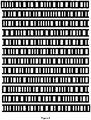
- Figure 6 displays the whole 2100 mm pattern in 1:1 scale (cut in pieces of 17,5 cm).
- the segments according to the pattern of the invention may be rectangular shaped and comprise a length and a width. Furthermore, the width of a least one segment may be of non-identical to the width of at least a second segment. Furthermore, at least one segment may be non-uniform width along its length. Such features allow vertical positioning in the pattern to be determined (See Figure 7 and 8 ).
- a region below a centre line and above the centre line of the pattern of the invention wherein the height of the region is defined by ⁇ y in [-1, 1].
- the thickness may change linearly according to ⁇ y within the region from a thickness of B -B/2 to a thickness of B +B/2.
- the thickness may change linearly according to ⁇ y within the region from 2B -B/2 to 2B +B/2.
- Pattern segments may be termed as either “odd” or “even” depending on their shape.
- the difference between “odd” and “even” white segments can be seen.
- the first (odd) white line starts thick at the top of and tapers down to thin at the bottom.
- the second (even) white line starts thin at the top of the figure and ends thick at the bottom.
- the "odd” characteristic is further shown in Figures 7 and 8 .
- the thickness of the middle part is B in Figure 7 (or 2B in Figure 8 ) plus ⁇ y B/2.
- the behavior is "swapped”: the line is thin on top and thick at the bottom. In the formula for the thickness, the sign is thus swapped from plus to minus.
- the thickness of the odd segments equals B + ⁇ y B/2, while for the even segments it equals B - ⁇ y B/2. This implies that the thickness of the dark segments remains unchanged. However their position shifts depending on ⁇ y.
- a detector for example a camera
- a calculation of ⁇ y either above or the center line may indicate a mis-alignment from centre and thus provides for the detector to be recalibrated to the centre line accordingly.
- a camera may be set to look at the pattern, but it may not be necessarily be looking parallel to the centre line of the pattern.
- a line scan camera has a single line of pixels that image across an object.
- the scan line of the camera may not be parallel with a physical centre line of the pattern. Therefore as viewed with the camera, a given pixel height position, for example in two different white segments, may appear at a different heights with respect to the scan line of the camera.
- a pixel height for each white segment of the pattern may be calculated.
- a linear line may be fitted through discrete points over a number of white segments.
- the height (y-position) for a certain x-position can be determined by evaluating the line at that position. This also provides that the angle between a centre line of the pattern and the scan line of the camera may be calculated. As such, the scan line of a camera may be defined by two values: the angle and a height at a specific position. When a camera is installed and aligned within a detector calibration system, it is desired to have both the angle and height set to zero. It may also be desirable to set different heights for different cameras if, for example, two cameras need to look at different parallel lines.
- Figure 9 shows a section of the pattern of the invention which may be utilized for camera alignment in the above described manner.
- a curved scan line rather than a linear scan line as described may be in use.
- a curve fitting may be performed on a number of discrete points to provide camera position information.
- utilizing multiple discrete points, rather than a single point, allows camera positioning to be determined for both linear and curved scan lines.
- the position on the pattern is determined by the edge locations of the light and dark segments, in effect the position data is encoded in the edges between dark and light segments.
- this allow for position detection down to a pixel level.
- the pixels within the dark areas and the pixels within the light areas of the pattern themselves are not used to determine a position within the pattern.
- the gray value of the pixel (2 pixels) at the edge may be examined.
- An alternative is to define a gray level pattern around the edge. This provides for use of multiple pixels in order to define the position of a local edge in subpixel precision.
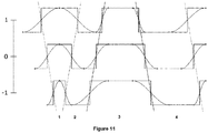
- the straight vertical and horizontal lines represent the gray values of an original pattern image.
- the curved lines are the gray values of the new image Note that the middle of the segments that are 2 bits wide are either completely light or completely dark (see straight lines in Figure 10 ).
- the image may be thresholded in the middle of the light and dark values (see dashed line) and the binarized image will have its edges at the same position as the original image. This will still result in edges at pixel positions.
- a line may be fitted through the values of the pixels around the detected edge-pixel. The intersection of this line with the threshold line will result in a sub-pixel position for the edge.
- the vertical lines indicate the linear shifting of the edges.
- the first two vertical lines indicated a narrowing of a light segment (1)
- the second and third vertical line indicate a shift in the edge position of a dark segment (2).
- the focus of a detector in a detector calibration system may be optimized by provided firstly a rough focus indication and a subsequent finer focus indication.
- a rough indication of a detectors focus on a pattern of segments may be achieved by analysing the standard deviation of the gray values in an image or frame grab obtained from the detector. For example, if the detector is out of focus the image will be a uniform gray. An intermediate indication of focus may be obtained from the difference in height (difference between maximum and minimum gray level) between segments of one bit width and two bit width. As such, the better the focus of the detector, the higher the calculated standard deviation. When the detector focus is sufficiently good to detect the pattern, a subsequent finer focus indication may be utilized.
- a first embodiment of a finer focus indication utilizes the presence of thin and thick white segments in the pattern. For a thin segment (using the sinusoidal transitions as described above) only one pixel will be at the highest intensity value. For the thick white segments there may be a whole plateau of pixels having the same high intensity. If the camera is out of focus the intensity values will be smoothed out and the top values and bottom values of the thin segments will come closer together. The ratio between the difference between top and bottom intensity values of the thin segments versus the difference of the top and bottom intensity values for the thick segments provides an indication of the quality of the detector focus. The closer the ratio value to 1, the better the focus.
- a second embodiment of a finer focus indication utilizes examining the segment edges without a sinusoidal transition. For example, every ninth segment edge may be a high contrast edge. Given that a bad focus will blur out this transition over multiple pixels, the highest difference between two adjacent pixels is measured around the segment edges without a sinusoidal transition. The higher the difference value the better the focus, i.e. indicating a strong transition from a white to black segment over two adjacent pixels.
- the fine focus measurements may be averaged out over all edges in order to get a stable indication. This provides the advantage that due to the high edge density (i.e multiple segments), the focus may be measured and optimized over a whole scan line and not only at specific points.
Landscapes
- Physics & Mathematics (AREA)
- General Physics & Mathematics (AREA)
- Health & Medical Sciences (AREA)
- Life Sciences & Earth Sciences (AREA)
- High Energy & Nuclear Physics (AREA)
- Molecular Biology (AREA)
- Spectroscopy & Molecular Physics (AREA)
- Length Measuring Devices By Optical Means (AREA)
- Focusing (AREA)
- Automatic Focus Adjustment (AREA)
Priority Applications (5)
| Application Number | Priority Date | Filing Date | Title |
|---|---|---|---|
| EP17175550.7A EP3415865A1 (fr) | 2017-06-12 | 2017-06-12 | Étalonnage de détecteur |
| US16/622,083 US20200191984A1 (en) | 2017-06-12 | 2018-06-11 | Detector calibration |
| PCT/EP2018/065362 WO2018228995A1 (fr) | 2017-06-12 | 2018-06-11 | Étalonnage de détecteur |
| JP2020518577A JP2020523611A (ja) | 2017-06-12 | 2018-06-11 | 検出器較正 |
| CN201880038887.XA CN110741222A (zh) | 2017-06-12 | 2018-06-11 | 检测器校准 |
Applications Claiming Priority (1)
| Application Number | Priority Date | Filing Date | Title |
|---|---|---|---|
| EP17175550.7A EP3415865A1 (fr) | 2017-06-12 | 2017-06-12 | Étalonnage de détecteur |
Publications (1)
| Publication Number | Publication Date |
|---|---|
| EP3415865A1 true EP3415865A1 (fr) | 2018-12-19 |
Family
ID=59257958
Family Applications (1)
| Application Number | Title | Priority Date | Filing Date |
|---|---|---|---|
| EP17175550.7A Ceased EP3415865A1 (fr) | 2017-06-12 | 2017-06-12 | Étalonnage de détecteur |
Country Status (5)
| Country | Link |
|---|---|
| US (1) | US20200191984A1 (fr) |
| EP (1) | EP3415865A1 (fr) |
| JP (1) | JP2020523611A (fr) |
| CN (1) | CN110741222A (fr) |
| WO (1) | WO2018228995A1 (fr) |
Cited By (1)
| Publication number | Priority date | Publication date | Assignee | Title |
|---|---|---|---|---|
| CN110556306A (zh) * | 2019-09-06 | 2019-12-10 | 北京施达优技术有限公司 | 缺陷检测方法和装置 |
Families Citing this family (1)
| Publication number | Priority date | Publication date | Assignee | Title |
|---|---|---|---|---|
| CN116164645B (zh) * | 2023-02-20 | 2023-08-08 | 浙江禾川科技股份有限公司 | 一种绝对位置检测方法、装置、设备及存储介质 |
Citations (5)
| Publication number | Priority date | Publication date | Assignee | Title |
|---|---|---|---|---|
| US4557599A (en) | 1984-03-06 | 1985-12-10 | General Signal Corporation | Calibration and alignment target plate |
| US5463429A (en) | 1993-11-15 | 1995-10-31 | Eastman Kodak Company | Surface inspection optical geometry alignment system |
| WO2010112082A1 (fr) * | 2009-04-03 | 2010-10-07 | Csem Centre Suisse D'electronique Et De Microtechnique Sa Recherche Et Developpement | Codeur de position unidimensionnel |
| US20150069225A1 (en) * | 2012-05-15 | 2015-03-12 | Korea Research Institute Of Standards And Science | Absolute position measurement method, absolute position measurement apparatus and scale |
| EP3064902A1 (fr) * | 2015-03-06 | 2016-09-07 | Hexagon Technology Center GmbH | Système de détermination de positions |
Family Cites Families (4)
| Publication number | Priority date | Publication date | Assignee | Title |
|---|---|---|---|---|
| CN100420259C (zh) * | 2003-11-27 | 2008-09-17 | 财团法人工业技术研究院 | 摄影机数组校准系统与方法 |
| KR101341804B1 (ko) * | 2012-05-15 | 2013-12-16 | 한국표준과학연구원 | 절대 위치 측정 방법, 절대 위치 측정 장치, 및 스케일 |
| CN105890634B (zh) * | 2016-04-07 | 2018-07-03 | 广东工业大学 | 一种绝对式编码器及其解码测量方法 |
| CN106643562B (zh) * | 2016-10-27 | 2019-05-03 | 天津大学 | 基于时域空域混合编码的结构光条纹投射方法 |
-
2017
- 2017-06-12 EP EP17175550.7A patent/EP3415865A1/fr not_active Ceased
-
2018
- 2018-06-11 WO PCT/EP2018/065362 patent/WO2018228995A1/fr not_active Ceased
- 2018-06-11 JP JP2020518577A patent/JP2020523611A/ja active Pending
- 2018-06-11 US US16/622,083 patent/US20200191984A1/en not_active Abandoned
- 2018-06-11 CN CN201880038887.XA patent/CN110741222A/zh active Pending
Patent Citations (5)
| Publication number | Priority date | Publication date | Assignee | Title |
|---|---|---|---|---|
| US4557599A (en) | 1984-03-06 | 1985-12-10 | General Signal Corporation | Calibration and alignment target plate |
| US5463429A (en) | 1993-11-15 | 1995-10-31 | Eastman Kodak Company | Surface inspection optical geometry alignment system |
| WO2010112082A1 (fr) * | 2009-04-03 | 2010-10-07 | Csem Centre Suisse D'electronique Et De Microtechnique Sa Recherche Et Developpement | Codeur de position unidimensionnel |
| US20150069225A1 (en) * | 2012-05-15 | 2015-03-12 | Korea Research Institute Of Standards And Science | Absolute position measurement method, absolute position measurement apparatus and scale |
| EP3064902A1 (fr) * | 2015-03-06 | 2016-09-07 | Hexagon Technology Center GmbH | Système de détermination de positions |
Non-Patent Citations (1)
| Title |
|---|
| LUNA ET AL., IEEE TRANSACTIONS ON INSTRUMENTATION AND MEASUREMENT, vol. 59, no. 8, August 2010 (2010-08-01) |
Cited By (1)
| Publication number | Priority date | Publication date | Assignee | Title |
|---|---|---|---|---|
| CN110556306A (zh) * | 2019-09-06 | 2019-12-10 | 北京施达优技术有限公司 | 缺陷检测方法和装置 |
Also Published As
| Publication number | Publication date |
|---|---|
| JP2020523611A (ja) | 2020-08-06 |
| WO2018228995A1 (fr) | 2018-12-20 |
| CN110741222A (zh) | 2020-01-31 |
| US20200191984A1 (en) | 2020-06-18 |
Similar Documents
| Publication | Publication Date | Title |
|---|---|---|
| EP1330111B1 (fr) | Technique d'évaluation et de correction automatique de la qualité d'image | |
| US5615003A (en) | Electromagnetic profile scanner | |
| US8139117B2 (en) | Image quality analysis with test pattern | |
| US20200371333A1 (en) | Microscopy method, microscope and computer program with verification algorithm for image processing results | |
| KR20110095344A (ko) | 성형 시트의 결함 검사 장치 | |
| US20160169818A1 (en) | Screening of electronic components for detection of counterfeit articles using automated inspection system | |
| US20140029796A1 (en) | Method for the optical identification of objects in motion | |
| US20120213425A1 (en) | Combining feature boundaries | |
| US7158690B2 (en) | Enhancing the resolution of measurement systems employing image capturing systems to measure lengths | |
| JP7062722B2 (ja) | 光学コードのモジュールサイズの特定 | |
| US20050275724A1 (en) | Image test target for visual determination of digital image resolution | |
| JP2002508069A (ja) | 測定マークおよび測定マークの検出方法並びに物体測量方法 | |
| CN111612757A (zh) | 一种屏幕裂纹的检测方法、装置、设备及存储介质 | |
| JPH10267628A (ja) | 3次元形状検出方法およびその装置並びに基板の製造方法 | |
| JP2004177139A (ja) | 検査条件データ作成支援プログラム及び検査装置及び検査条件データ作成方法 | |
| US20200191984A1 (en) | Detector calibration | |
| CN109029309A (zh) | 一种对线宽量测机进行校准的方法 | |
| CN115760860A (zh) | 一种基于dxf文件导入的多类型工件尺寸视觉测量方法 | |
| US12190543B2 (en) | Lens calibration method for digital imaging apparatus | |
| CN116485872B (zh) | 一种基于丝型像质计丝径测量的图像比例尺计算方法 | |
| JPH0339603A (ja) | パターンの輪郭検出方法及びこの方法を用いた測長装置 | |
| US6720989B2 (en) | System and method for automatically inspecting an array of periodic elements | |
| CN112129768A (zh) | 外观检查管理系统、装置、方法以及存储介质 | |
| JPH03188357A (ja) | 印字品質評価方法 | |
| CN120070599B (zh) | 缩放系数确定方法及相关装置、安检机和存储介质 |
Legal Events
| Date | Code | Title | Description |
|---|---|---|---|
| PUAI | Public reference made under article 153(3) epc to a published international application that has entered the european phase |
Free format text: ORIGINAL CODE: 0009012 |
|
| STAA | Information on the status of an ep patent application or granted ep patent |
Free format text: STATUS: THE APPLICATION HAS BEEN PUBLISHED |
|
| AK | Designated contracting states |
Kind code of ref document: A1 Designated state(s): AL AT BE BG CH CY CZ DE DK EE ES FI FR GB GR HR HU IE IS IT LI LT LU LV MC MK MT NL NO PL PT RO RS SE SI SK SM TR |
|
| AX | Request for extension of the european patent |
Extension state: BA ME |
|
| STAA | Information on the status of an ep patent application or granted ep patent |
Free format text: STATUS: REQUEST FOR EXAMINATION WAS MADE |
|
| 17P | Request for examination filed |
Effective date: 20190619 |
|
| RBV | Designated contracting states (corrected) |
Designated state(s): AL AT BE BG CH CY CZ DE DK EE ES FI FR GB GR HR HU IE IS IT LI LT LU LV MC MK MT NL NO PL PT RO RS SE SI SK SM TR |
|
| STAA | Information on the status of an ep patent application or granted ep patent |
Free format text: STATUS: EXAMINATION IS IN PROGRESS |
|
| 17Q | First examination report despatched |
Effective date: 20191023 |
|
| STAA | Information on the status of an ep patent application or granted ep patent |
Free format text: STATUS: THE APPLICATION HAS BEEN REFUSED |
|
| 18R | Application refused |
Effective date: 20210313 |