EP3417227B1 - Échangeur de chaleur, en particulier échangeur de chaleur eau-air ou échangeur de chaleur huile-eau - Google Patents
Échangeur de chaleur, en particulier échangeur de chaleur eau-air ou échangeur de chaleur huile-eau Download PDFInfo
- Publication number
- EP3417227B1 EP3417227B1 EP17707776.5A EP17707776A EP3417227B1 EP 3417227 B1 EP3417227 B1 EP 3417227B1 EP 17707776 A EP17707776 A EP 17707776A EP 3417227 B1 EP3417227 B1 EP 3417227B1
- Authority
- EP
- European Patent Office
- Prior art keywords
- heat exchanger
- fluid
- water
- oil
- receiving volume
- Prior art date
- Legal status (The legal status is an assumption and is not a legal conclusion. Google has not performed a legal analysis and makes no representation as to the accuracy of the status listed.)
- Active
Links
Images

Classifications
-
- F—MECHANICAL ENGINEERING; LIGHTING; HEATING; WEAPONS; BLASTING
- F24—HEATING; RANGES; VENTILATING
- F24D—DOMESTIC- OR SPACE-HEATING SYSTEMS, e.g. CENTRAL HEATING SYSTEMS; DOMESTIC HOT-WATER SUPPLY SYSTEMS; ELEMENTS OR COMPONENTS THEREFOR
- F24D13/00—Electric heating systems
- F24D13/04—Electric heating systems using electric heating of heat-transfer fluid in separate units of the system
-
- F—MECHANICAL ENGINEERING; LIGHTING; HEATING; WEAPONS; BLASTING
- F24—HEATING; RANGES; VENTILATING
- F24H—FLUID HEATERS, e.g. WATER OR AIR HEATERS, HAVING HEAT-GENERATING MEANS, e.g. HEAT PUMPS, IN GENERAL
- F24H9/00—Details
- F24H9/18—Arrangement or mounting of grates or heating means
- F24H9/1809—Arrangement or mounting of grates or heating means for water heaters
- F24H9/1818—Arrangement or mounting of electric heating means
-
- F—MECHANICAL ENGINEERING; LIGHTING; HEATING; WEAPONS; BLASTING
- F28—HEAT EXCHANGE IN GENERAL
- F28F—DETAILS OF HEAT-EXCHANGE AND HEAT-TRANSFER APPARATUS, OF GENERAL APPLICATION
- F28F13/00—Arrangements for modifying heat-transfer, e.g. increasing, decreasing
-
- F—MECHANICAL ENGINEERING; LIGHTING; HEATING; WEAPONS; BLASTING
- F28—HEAT EXCHANGE IN GENERAL
- F28F—DETAILS OF HEAT-EXCHANGE AND HEAT-TRANSFER APPARATUS, OF GENERAL APPLICATION
- F28F13/00—Arrangements for modifying heat-transfer, e.g. increasing, decreasing
- F28F13/18—Arrangements for modifying heat-transfer, e.g. increasing, decreasing by applying coatings, e.g. radiation-absorbing, radiation-reflecting; by surface treatment, e.g. polishing
-
- F—MECHANICAL ENGINEERING; LIGHTING; HEATING; WEAPONS; BLASTING
- F24—HEATING; RANGES; VENTILATING
- F24H—FLUID HEATERS, e.g. WATER OR AIR HEATERS, HAVING HEAT-GENERATING MEANS, e.g. HEAT PUMPS, IN GENERAL
- F24H2250/00—Electrical heat generating means
- F24H2250/02—Resistances
-
- F—MECHANICAL ENGINEERING; LIGHTING; HEATING; WEAPONS; BLASTING
- F28—HEAT EXCHANGE IN GENERAL
- F28D—HEAT-EXCHANGE APPARATUS, NOT PROVIDED FOR IN ANOTHER SUBCLASS, IN WHICH THE HEAT-EXCHANGE MEDIA DO NOT COME INTO DIRECT CONTACT
- F28D1/00—Heat-exchange apparatus having stationary conduit assemblies for one heat-exchange medium only, the media being in contact with different sides of the conduit wall, in which the other heat-exchange medium is a large body of fluid, e.g. domestic or motor car radiators
- F28D1/02—Heat-exchange apparatus having stationary conduit assemblies for one heat-exchange medium only, the media being in contact with different sides of the conduit wall, in which the other heat-exchange medium is a large body of fluid, e.g. domestic or motor car radiators with heat-exchange conduits immersed in the body of fluid
- F28D1/04—Heat-exchange apparatus having stationary conduit assemblies for one heat-exchange medium only, the media being in contact with different sides of the conduit wall, in which the other heat-exchange medium is a large body of fluid, e.g. domestic or motor car radiators with heat-exchange conduits immersed in the body of fluid with tubular conduits
- F28D1/053—Heat-exchange apparatus having stationary conduit assemblies for one heat-exchange medium only, the media being in contact with different sides of the conduit wall, in which the other heat-exchange medium is a large body of fluid, e.g. domestic or motor car radiators with heat-exchange conduits immersed in the body of fluid with tubular conduits the conduits being straight
- F28D1/05316—Assemblies of conduits connected to common headers, e.g. core type radiators
-
- F—MECHANICAL ENGINEERING; LIGHTING; HEATING; WEAPONS; BLASTING
- F28—HEAT EXCHANGE IN GENERAL
- F28D—HEAT-EXCHANGE APPARATUS, NOT PROVIDED FOR IN ANOTHER SUBCLASS, IN WHICH THE HEAT-EXCHANGE MEDIA DO NOT COME INTO DIRECT CONTACT
- F28D21/00—Heat-exchange apparatus not covered by any of the groups F28D1/00 - F28D20/00
- F28D2021/0019—Other heat exchangers for particular applications; Heat exchange systems not otherwise provided for
- F28D2021/008—Other heat exchangers for particular applications; Heat exchange systems not otherwise provided for for vehicles
- F28D2021/0089—Oil coolers
-
- F—MECHANICAL ENGINEERING; LIGHTING; HEATING; WEAPONS; BLASTING
- F28—HEAT EXCHANGE IN GENERAL
- F28D—HEAT-EXCHANGE APPARATUS, NOT PROVIDED FOR IN ANOTHER SUBCLASS, IN WHICH THE HEAT-EXCHANGE MEDIA DO NOT COME INTO DIRECT CONTACT
- F28D21/00—Heat-exchange apparatus not covered by any of the groups F28D1/00 - F28D20/00
- F28D2021/0019—Other heat exchangers for particular applications; Heat exchange systems not otherwise provided for
- F28D2021/008—Other heat exchangers for particular applications; Heat exchange systems not otherwise provided for for vehicles
- F28D2021/0091—Radiators
- F28D2021/0094—Radiators for recooling the engine coolant
-
- F—MECHANICAL ENGINEERING; LIGHTING; HEATING; WEAPONS; BLASTING
- F28—HEAT EXCHANGE IN GENERAL
- F28D—HEAT-EXCHANGE APPARATUS, NOT PROVIDED FOR IN ANOTHER SUBCLASS, IN WHICH THE HEAT-EXCHANGE MEDIA DO NOT COME INTO DIRECT CONTACT
- F28D9/00—Heat-exchange apparatus having stationary plate-like or laminated conduit assemblies for both heat-exchange media, the media being in contact with different sides of a conduit wall
- F28D9/0031—Heat-exchange apparatus having stationary plate-like or laminated conduit assemblies for both heat-exchange media, the media being in contact with different sides of a conduit wall the conduits for one heat-exchange medium being formed by paired plates touching each other
- F28D9/0043—Heat-exchange apparatus having stationary plate-like or laminated conduit assemblies for both heat-exchange media, the media being in contact with different sides of a conduit wall the conduits for one heat-exchange medium being formed by paired plates touching each other the plates having openings therein for circulation of at least one heat-exchange medium from one conduit to another
- F28D9/005—Heat-exchange apparatus having stationary plate-like or laminated conduit assemblies for both heat-exchange media, the media being in contact with different sides of a conduit wall the conduits for one heat-exchange medium being formed by paired plates touching each other the plates having openings therein for circulation of at least one heat-exchange medium from one conduit to another the plates having openings therein for both heat-exchange media
-
- F—MECHANICAL ENGINEERING; LIGHTING; HEATING; WEAPONS; BLASTING
- F28—HEAT EXCHANGE IN GENERAL
- F28F—DETAILS OF HEAT-EXCHANGE AND HEAT-TRANSFER APPARATUS, OF GENERAL APPLICATION
- F28F9/00—Casings; Header boxes; Auxiliary supports for elements; Auxiliary members within casings
- F28F9/02—Header boxes; End plates
-
- H—ELECTRICITY
- H05—ELECTRIC TECHNIQUES NOT OTHERWISE PROVIDED FOR
- H05B—ELECTRIC HEATING; ELECTRIC LIGHT SOURCES NOT OTHERWISE PROVIDED FOR; CIRCUIT ARRANGEMENTS FOR ELECTRIC LIGHT SOURCES, IN GENERAL
- H05B2203/00—Aspects relating to Ohmic resistive heating covered by group H05B3/00
- H05B2203/013—Heaters using resistive films or coatings
-
- H—ELECTRICITY
- H05—ELECTRIC TECHNIQUES NOT OTHERWISE PROVIDED FOR
- H05B—ELECTRIC HEATING; ELECTRIC LIGHT SOURCES NOT OTHERWISE PROVIDED FOR; CIRCUIT ARRANGEMENTS FOR ELECTRIC LIGHT SOURCES, IN GENERAL
- H05B3/00—Ohmic-resistance heating
- H05B3/10—Heating elements characterised by the composition or nature of the materials or by the arrangement of the conductor
- H05B3/12—Heating elements characterised by the composition or nature of the materials or by the arrangement of the conductor characterised by the composition or nature of the conductive material
Definitions
- the invention relates to a heat exchanger, in particular a water-air heat exchanger or an oil-water heat exchanger according to claim 1, and a method for producing a heat exchanger, in particular a water-air heat exchanger or an oil-water heat exchanger according to claim 6.
- EP 2 466 241 A1 describes an oil-water heat exchanger with several pan elements stacked on top of one another and soldered together.
- Such oil-water heat exchangers are usually integrated into the cooling circuit of internal combustion engines and can be used, for example, to cool the engine oil.
- an electric heater is proposed there in an interior space of the heat exchanger in order to heat one of the interacting fluids of the heat exchanger.
- DE 10 2013 010 907 A1 shows an electrical heating device for heating a first medium and a second medium according to the preamble of claim 1, comprising at least one pipe carrying the second medium, a heat exchanger which is in thermally conductive contact with the at least one pipe and which carries the first medium, and a Layer heating element that at least partially covers the surface of the at least one tube.
- FR 2 966 580 A1 shows a heat exchanger which has a collector box for receiving a coolant and a radiator in which the coolant is circulated.
- the collector box contains an electrical heating element, for example an electric immersion heater, which is provided with an active part which extends into an internal volume defined by the collector box.
- heaters are described that have an electrical heating layer that heats up when an electrical voltage is applied (or when a current flows).
- DE 10 2011 006 248 A1 A household refrigerator with a heating device is described there.
- the heating device is produced as a layer heater by painting and applied to a surface of an evaporator of the household refrigerator.
- the stratified heating is according to DE 10 2011 006 248 A1 Directly applied over a surface of the evaporator and hardly thermally insulating in order to impair the functionality of the evaporator as little as possible.
- it is considered to be disadvantageous that the production according to this prior art is comparatively complex and appears to be tailored to a very special application. It is the object of the invention to propose a heat exchanger which enables a fluid flowing through the heat exchanger to be heated in a simple and effective manner.
- a heat exchanger in particular water-air heat exchanger or oil-water heat exchanger, comprising at least one first fluid channel for guiding a first fluid (e.g. oil from an oil-water heat exchanger or water from a water-air heat exchanger ), as well as at least one second fluid channel for guiding a second fluid (e.g. water of the oil-water heat exchanger or air of the water-air heat exchanger), the at least one first fluid channel being connected to a fluid receiving volume (in particular the outlet side), the fluid receiving volume is equipped with an electrical heating coating, wherein the fluid receiving volume is provided by a separate module, wherein the separate module can be or is attached to the remaining components of the heat exchanger.
- the heat exchanger can generally be a liquid-liquid heat exchanger or a liquid-gas heat exchanger or a gas-gas heat exchanger.
- a core idea of the invention is that of the per se, for example WO 2013/186106 A1 or WO 2013/030048 A1 known electrical heating coatings to apply to a fluid receiving volume which is connected to at least one of the fluid channels.
- a fluid to be heated with the heat exchanger can effectively be additionally heated or the temperature of a heating fluid can be increased further (in particular if the electrical heating coating is connected on the inlet side to a fluid channel of the heating fluid).
- a fluid can be effectively heated, for example an oil of an oil-water heat exchanger for an internal combustion engine of a motor vehicle can be heated.
- the heat exchanger can have several first fluid channels and / or several second fluid channels.
- the fluid receiving volume is a volume of the heat exchanger before (or after) the fluid is distributed to a plurality of individual fluid channels (that is to say, for example, a fluid collecting device or fluid distributing device).
- the first fluid can be oil or water.
- the second fluid can be water or air.
- the first and / or second fluid can be liquid or gaseous.
- the fluid receiving volume is defined by a fluid receiving container, in particular an oil receiving container.
- a fluid receiving container in particular an oil receiving container, is preferably connected on the outlet side to one or more fluid channels through which oil preferably flows.
- the fluid receiving volume can be defined by a connection pipe, in particular an outlet pipe, preferably an oil-water heat exchanger.
- a connection pipe in particular an outlet pipe, preferably an oil-water heat exchanger.
- a turbulator can be provided. This is preferably provided in the vicinity of an electrical heating coating (ie in particular not further than 5 cm, in particular 2 cm away).
- the turbulator can be arranged inside the outlet pipe (provided with an electrical heating coating).
- the electrical heating coating can be arranged on an outer wall of the fluid receiving volume (for example outlet pipe) or on an inner wall of the fluid receiving volume (for example outlet pipe). If a turbulator is provided, it can optionally also be provided with an electrical heating coating itself.
- the fluid receiving volume is provided by a separate module, the separate module being attachable or being attached to the other components of the heat exchanger.
- a separate fluid receiving volume is proposed so that existing heat exchangers (in particular oil-water heat exchangers) can be further improved by a simple upgrade.
- the modular design of the fluid intake volume also has the advantage that manufacturing costs can possibly be reduced, for example by using the same fluid intake module for different types and / or sizes of heat exchangers.
- the heating coating is particularly preferably designed for operation in the low-voltage range, preferably for 12 volts, 24 volts or 48 volts.
- Appropriate electrical and / or electronic components of the oil-water heat exchanger are then preferably also designed for such a low-voltage range (12 volts, 24 volts or 48 volts).
- "Low-voltage range” should preferably be understood to mean an operating voltage of less than 100 V, in particular less than 60 V (direct current).
- the heating coating is applied indirectly, in particular via an insulation layer, to or in the fluid receiving volume.
- an insulation layer can be formed, for example, by an adhesion promoter layer or attached to the oil-water heat exchanger via such a layer.
- a polymer material or a ceramic material (for example Al 2 O 3 ) can preferably be used for the insulation layer.
- the insulating layer is provided by passivation, in particular oxidizing, in particular anodizing (of aluminum or an aluminum alloy), preferably a surface, for example an outer and / or inner surface, of the fluid receiving volume. Overall, simple yet adequate electrical insulation is provided (especially in low-voltage applications).
- the heating coating can even be applied directly to or in the fluid receiving volume (for example in low-voltage applications and / or if the substrate is not or only poorly electrically conductive).
- the heating coating and / or insulation layer is preferably applied over the entire surface of the fluid receiving volume.
- the heating coating and / or the insulation layer can have an (at least essentially) constant layer thickness.
- the heating coating and / or the insulation layer can per se be designed to be dimensionally unstable (or not self-supporting).
- a substrate can be dispensed with, so that the heating coating (and an optional insulation layer) may be formed free of a substrate.
- a possibly necessary carrying and / or support structure can be provided by the fluid receiving volume (or a wall of the same).
- the heating coating can be materially connected to a surface, in particular an outer and / or inner surface, of the fluid receiving volume.
- the heating coating is designed as a continuous (in particular unstructured and / or uninterrupted) layer.
- the heating coating can generally have at least one section within which there are no interruptions in the heating coating in two mutually perpendicular directions over a distance of at least 1 cm, preferably at least 2 cm, even more preferably at least 4 cm.
- the heating coating can comprise at least one rectangular section with a length and a width of at least 1 cm, preferably at least 2 cm, even more preferably at least 4 cm, within which there are no interruptions or possibly other structures in the heating coating.
- An “interruption” within the heating coating is to be understood as a section through which no current can flow, for example because this section remains (completely) free of material and / or is (at least partially) filled with an insulator.
- the heating coating can be (thermally) sprayed on (regardless of whether it is unstructured or structured, in the final state). In this context it has surprisingly been found that even such a simply configured heating coating can bring about sufficient heating of the oil.
- the heating coating is designed as a structured layer.
- the heating coating is preferably structured by a masking process (preferably using silicone, which can be embossed).
- a masking process preferably using silicone, which can be embossed.
- the insulating layer described above can have a thickness of at least 50 ⁇ m, preferably at least 200 ⁇ m and / or at most 1000 ⁇ m, preferably at most 500 ⁇ m.
- the heating coating preferably has a height (thickness) of at least 5 ⁇ m, preferably at least 10 ⁇ m and / or at most 1 mm, preferably at most 500 ⁇ m, even more preferably at most 30 ⁇ m, even more preferably at most 20 ⁇ m.
- a conductor path defined by the heating coating can be at least 1 mm, preferably at least 3 mm, even more preferably at least 5 mm, even more preferably at least 10 mm, more preferably at least 30 mm wide. “Width” should be understood to mean the extension of the conductor track perpendicular to its longitudinal extension (which usually also defines the direction of the current flow).
- a protective cover for example a silicone protective layer, is attached over the heating coating.
- the heating coating can also define an outside or inside of the fluid receiving volume (in an embodiment that is particularly easy to manufacture).
- the oil-water heat exchanger has a plurality of modules, in particular tub elements, which further preferably, as in FIG EP 2 466 241 A1 described, can be formed.
- the oil-water heat exchanger (apart from the fluid holding volume according to the invention) as in EP 2 466 241 A1 or US 2015/0176913 A1 described, be formed.
- the disclosure of these documents is hereby explicitly incorporated by reference.
- at least one heating coating can be arranged between two modules.
- the oil-water heat exchanger comprises several pan elements, at least one heating coating can optionally be arranged (applied) between two of these pan elements (on one of the pan elements).
- an additional heating coating can be applied to further surfaces of the heat exchanger.
- the object is also achieved by a method for producing a heat exchanger, in particular a water-air heat exchanger or an oil-water heat exchanger, in particular of the type described above, according to claim 6, comprising the provision of at least one first fluid channel for guiding a first fluid (e.g. an oil of the oil-water heat exchanger or water of the water-air heat exchanger) and at least one second fluid channel for guiding a second fluid (e.g. water of the oil-water heat exchanger or air of the water-air heat exchanger), the at least one first fluid channel is connected to a fluid receiving volume, in particular on the outlet side, the fluid receiving volume being equipped with an electrical heating coating (or a surface of the fluid receiving volume being coated directly or indirectly with the electrical heating coating).
- a first fluid channel for guiding a first fluid
- a second fluid channel e.g. water of the oil-water heat exchanger or air of the water-air heat exchanger
- the application of an insulating layer to a surface of the fluid receiving volume can be carried out (or a surface of the fluid receiving volume can be coated directly or indirectly with the insulating layer), for example by passivation (oxidation, in particular anodizing) of a substrate, for example a heat exchanger housing. If necessary, the electrical heating coating can be sprayed on (thermally).
- passivation oxygen, in particular anodizing
- the electrical heating coating can be sprayed on (thermally).
- the above-mentioned object is also achieved by using a heat exchanger of the type described above or produced according to the type described above, as a water-air heat exchanger or as an oil-water heat exchanger, in particular for the internal combustion engine of a motor vehicle.
- the insulating layer can be a ceramic material or a polymer material or consist of such a material, Al 2 O 3, for example, being considered as the ceramic material.
- the heating layer can be applied, for example, in a plasma coating process, in particular plasma spraying, or in a screen printing process, or as a resistance paste, in particular on the insulating layer.
- a plasma coating process for example, an electrically conductive layer can first be applied, in particular to the insulating layer. Areas can then be cut out of the electrically conductive layer so that one or more conductor tracks remain.
- a masking technique is preferably used.
- the conductor tracks can then form the heating resistor or several heating resistors.
- the areas mentioned can be cut out of the conductive layer, for example by means of a laser.
- the heating coating can for example be a metal layer and possibly contain nickel and / or chromium or consist of these materials. For example 70-90% nickel and 10-30% chromium can be used, with a ratio of 80% nickel and 20% chromium being considered to be suitable.
- the heating coating can, for example, occupy an area of at least 5 cm 2 , preferably at least 10 cm 2 and / or at most 200 cm 2 , preferably at most 100 cm 2 .
- the oil-water heat exchanger can have a total volume of preferably at least 200 cm 3 , even more preferably at least 500 cm 3 , even more preferably at least 800 cm 3 and / or at most 5000 cm 3 , preferably at most 2000 cm 3 .
- the oil-water heat exchanger can be 15-25 cm long and / or 8-12 cm wide and / or 3-7 cm high (thick).
- the oil-water heat exchanger preferably has one or more first fluid channels for guiding the oil and one or more second fluid channels for guiding the water.
- a bimetal switch possibly with two redundant switch devices, can be provided for controlling, in particular regulating, the electrical heating coating.
- Fig. 1 shows a schematic view of an oil-water heat exchanger (as shown in detail, for example, in EP 2 466 241 A1 is described) with several (soldered) pan elements 10, a cover 19, an inlet pipe 11 and an outlet pipe 12 for the oil flowing in the heat exchanger.
- An electrical heating coating 13 is applied at least to the outlet pipe 12 (possibly in the inlet pipe 11).
- an electrical heating coating 13 is arranged on a fluid receiving container 14.
- the fluid receiving container 14 has a (significantly) enlarged diameter compared to the outlet pipe 12 according to FIG Figure 1 or a fluid receiving container outlet pipe 15 so that the fluid (oil) can be stored in the fluid receiving container 14.
- the fluid receiving container 14 can be, for example, a cuboid or cylindrical body.
- the fluid receiving container 14 is provided as an additional module which is connected to an outlet 20 of a heat exchanger main body 21. It would also be conceivable to design the fluid receiving container 14 as an integral part of the oil-water heat exchanger, so that the outlet 20 can be omitted.
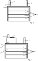
- FIG. 3 A water-air heat exchanger is shown, which has a collecting box 16 and heat exchanger tubes 17, with water for heating (or cooling) a gas (in particular air) flowing past the heat exchanger tubes 17 being provided through both the collecting container 16 and the heat exchanger tubes 17. There is an electrical heating coating 13 on the collecting box 16.
- a plurality of heat exchanger tubes 17 are connected to the collecting box 16 via connection pieces 18. At least 3, or at least 5, or at least 20 heat exchanger tubes 17 can be connected to the same collecting box 16.
- the water can enter via an inlet (inlet pipe 11) and exit via an outlet (outlet pipe 12).
Landscapes
- Engineering & Computer Science (AREA)
- Physics & Mathematics (AREA)
- Thermal Sciences (AREA)
- Mechanical Engineering (AREA)
- General Engineering & Computer Science (AREA)
- Chemical & Material Sciences (AREA)
- Combustion & Propulsion (AREA)
- Heat-Exchange Devices With Radiators And Conduit Assemblies (AREA)
- Lubrication Of Internal Combustion Engines (AREA)
Claims (7)
- Échangeur de chaleur, notamment échangeur de chaleur eau-air ou échangeur de chaleur huile-eau, comprenant au moins un premier canal de fluide pour l'acheminement d'un premier fluide, ainsi qu'au moins un deuxième canal de fluide pour l'acheminement d'un deuxième fluide,
l'au moins un premier canal de fluide étant raccordé à un volume de réception de fluide, notamment côté sortie, le volume de réception de fluide étant équipé d'un revêtement chauffant électrique (13),
caractérisé en ce que
le volume de réception de fluide est fourni par un module séparé, le module séparé pouvant être fixé ou étant fixé aux autres constituants de l'échangeur de chaleur. - Échangeur de chaleur selon la revendication 1, caractérisé en ce que le volume de réception de fluide est défini par un contenant de réception de fluide (14), notamment un contenant de réception d'huile.
- Échangeur de chaleur selon la revendication 1 ou 2, caractérisé en ce que le volume de réception de fluide est défini par un tube de raccordement, notamment un tube de sortie (12).
- Échangeur de chaleur selon l'une quelconque des revendications précédentes, caractérisé en ce qu'un générateur de turbulence est prévu, de préférence à proximité d'un revêtement chauffant électrique (13).
- Échangeur de chaleur selon l'une quelconque des revendications précédentes, caractérisé en ce que le revêtement chauffant électrique (13) est conçu pour une exploitation dans la plage basse tension, de préférence pour 12 volt, 24 volt ou 48 volt.
- Procédé de fabrication d'un échangeur de chaleur, notamment d'un échangeur de chaleur eau-air ou d'un échangeur de chaleur huile-eau, comprenant les étapes suivantes :- la fourniture d'au moins un premier canal de fluide pour l'acheminement d'un premier fluide, ainsi que d'un deuxième canal de fluide pour l'acheminement d'un deuxième fluide, l'au moins un premier canal de fluide étant raccordé à un volume de réception de fluide, notamment côté sortie, le volume de réception de fluide étant équipé d'un revêtement chauffant électrique (13), le volume de réception de fluide étant fourni par un module séparé, le module séparé pouvant être fixé ou étant fixé aux autres constituants de l'échangeur de chaleur.
- Utilisation d'un échangeur de chaleur selon l'une quelconque des revendications 1 à 5, de préférence fabriqué selon la revendication 6, en tant qu'échangeur de chaleur eau-air ou en tant qu'échangeur de chaleur huile-eau, notamment pour le moteur à combustion d'un véhicule automobile.
Applications Claiming Priority (2)
| Application Number | Priority Date | Filing Date | Title |
|---|---|---|---|
| DE102016102895.9A DE102016102895A1 (de) | 2016-02-18 | 2016-02-18 | Wärmetauscher, insbesondere Wasser-Luft-Wärmetauscher oder Öl-Wasser-Wärmetauscher |
| PCT/EP2017/053280 WO2017140668A1 (fr) | 2016-02-18 | 2017-02-14 | Échangeur de chaleur, notamment échangeur de chaleur eau-air ou échangeur de chaleur huile-eau |
Publications (2)
| Publication Number | Publication Date |
|---|---|
| EP3417227A1 EP3417227A1 (fr) | 2018-12-26 |
| EP3417227B1 true EP3417227B1 (fr) | 2021-06-23 |
Family
ID=58191391
Family Applications (1)
| Application Number | Title | Priority Date | Filing Date |
|---|---|---|---|
| EP17707776.5A Active EP3417227B1 (fr) | 2016-02-18 | 2017-02-14 | Échangeur de chaleur, en particulier échangeur de chaleur eau-air ou échangeur de chaleur huile-eau |
Country Status (7)
| Country | Link |
|---|---|
| US (1) | US11384943B2 (fr) |
| EP (1) | EP3417227B1 (fr) |
| JP (2) | JP2019507277A (fr) |
| KR (1) | KR20180112836A (fr) |
| CN (1) | CN108700383A (fr) |
| DE (1) | DE102016102895A1 (fr) |
| WO (1) | WO2017140668A1 (fr) |
Families Citing this family (5)
| Publication number | Priority date | Publication date | Assignee | Title |
|---|---|---|---|---|
| CN111819403B (zh) | 2018-03-07 | 2022-07-08 | 达纳加拿大公司 | 带有一体式电加热元件和多个流体流动通路的热交换器 |
| CN109812864A (zh) * | 2018-11-14 | 2019-05-28 | 赵荣军 | 一种分集式自然循环取暖器 |
| DE102019213319A1 (de) * | 2019-09-03 | 2021-03-04 | Mahle International Gmbh | Wärmeübertrager |
| FR3102550A1 (fr) * | 2019-10-29 | 2021-04-30 | Valeo Systemes Thermiques | Échangeur de chaleur à plaques comprenant un élément électrique chauffant |
| KR20250151820A (ko) * | 2024-04-15 | 2025-10-22 | 한온시스템 주식회사 | 열교환기 어셈블리 |
Family Cites Families (23)
| Publication number | Priority date | Publication date | Assignee | Title |
|---|---|---|---|---|
| JPH01150096A (ja) * | 1987-12-04 | 1989-06-13 | Hitachi Metals Ltd | 保温機能を有する導管 |
| JP3015829B2 (ja) * | 1992-10-02 | 2000-03-06 | 株式会社小野測器 | エンジン潤滑油温度制御装置 |
| JP3855507B2 (ja) * | 1998-12-16 | 2006-12-13 | 株式会社デンソー | 暖房用熱交換器 |
| US6178292B1 (en) * | 1997-02-06 | 2001-01-23 | Denso Corporation | Core unit of heat exchanger having electric heater |
| JP2002283835A (ja) * | 2001-03-27 | 2002-10-03 | Calsonic Kansei Corp | 暖房用加熱器及び暖房用熱交換器 |
| DE10157399B4 (de) * | 2001-11-23 | 2008-04-10 | Webasto Ag | Heizkörper mit zwei wärmezuführenden Einrichtungen |
| JP4280545B2 (ja) * | 2003-05-14 | 2009-06-17 | カルソニックカンセイ株式会社 | 複合型熱交換器 |
| JP2004352057A (ja) * | 2003-05-28 | 2004-12-16 | Denso Corp | 車両用空調装置 |
| JP4958561B2 (ja) * | 2003-12-22 | 2012-06-20 | インテグリス・インコーポレーテッド | ポッティングされた中空導管を備える交換装置および製造方法 |
| KR101138668B1 (ko) * | 2005-01-12 | 2012-07-02 | 한라공조주식회사 | 열교환기 |
| JP2010113803A (ja) * | 2007-02-14 | 2010-05-20 | Nasakoa Kk | 導電性セラミックス層を使用した加熱方法とエンジン |
| US8752615B2 (en) * | 2008-01-08 | 2014-06-17 | General Electric Company | Methods and systems for controlling temperature in a vessel |
| WO2010138835A2 (fr) * | 2009-05-28 | 2010-12-02 | Gmz Energy, Inc. | Système thermoélectrique et procédé de fonctionnement associé |
| DE102010031468A1 (de) * | 2010-07-16 | 2012-01-19 | Behr Gmbh & Co. Kg | Fluidkanal für einen Wärmetauscher |
| FR2966580B1 (fr) * | 2010-10-20 | 2014-01-03 | Valeo Systemes Thermiques | Echangeur de chaleur et installation de ventilation et de chauffage correspondante |
| DE102010063141A1 (de) | 2010-12-15 | 2012-06-21 | Mahle International Gmbh | Wärmetauscher |
| DE102011003296A1 (de) * | 2011-01-28 | 2012-08-02 | Behr Gmbh & Co. Kg | Wärmeübertrager |
| DE102011006248A1 (de) | 2011-03-28 | 2012-10-04 | BSH Bosch und Siemens Hausgeräte GmbH | Kältegerät mit einer Heizvorrichtung |
| DE102011081831A1 (de) | 2011-08-30 | 2013-02-28 | Webasto Ag | Elektrische Heizeinheit, Heizvorrichtung für ein Fahrzeug und Verfahren zur Herstellung einer Heizeinheit |
| DE102012209936A1 (de) | 2012-06-13 | 2013-12-19 | Webasto Ag | Elektrische Heizeinrichtung für ein Kraftfahrzeug |
| DE102013010907A1 (de) * | 2013-06-28 | 2014-12-31 | Webasto SE | Elektrische Heizeinrichtung und Verfahren zur Herstellung einer elektrischen Heizeinrichtung |
| US20150093523A1 (en) * | 2013-09-30 | 2015-04-02 | Kyle Ryan Kissell | Heatable coating with nanomaterials |
| WO2015089671A1 (fr) | 2013-12-19 | 2015-06-25 | Dana Canada Corporation | Échangeur thermique conique |
-
2016
- 2016-02-18 DE DE102016102895.9A patent/DE102016102895A1/de not_active Withdrawn
-
2017
- 2017-02-14 CN CN201780011980.7A patent/CN108700383A/zh active Pending
- 2017-02-14 WO PCT/EP2017/053280 patent/WO2017140668A1/fr not_active Ceased
- 2017-02-14 JP JP2018542164A patent/JP2019507277A/ja active Pending
- 2017-02-14 EP EP17707776.5A patent/EP3417227B1/fr active Active
- 2017-02-14 US US15/999,656 patent/US11384943B2/en active Active
- 2017-02-14 KR KR1020187026348A patent/KR20180112836A/ko not_active Ceased
-
2021
- 2021-02-25 JP JP2021028137A patent/JP7032683B2/ja active Active
Non-Patent Citations (1)
| Title |
|---|
| None * |
Also Published As
| Publication number | Publication date |
|---|---|
| JP2019507277A (ja) | 2019-03-14 |
| WO2017140668A1 (fr) | 2017-08-24 |
| KR20180112836A (ko) | 2018-10-12 |
| US20210207816A1 (en) | 2021-07-08 |
| JP2021101143A (ja) | 2021-07-08 |
| CN108700383A (zh) | 2018-10-23 |
| EP3417227A1 (fr) | 2018-12-26 |
| JP7032683B2 (ja) | 2022-03-09 |
| US11384943B2 (en) | 2022-07-12 |
| DE102016102895A1 (de) | 2017-08-24 |
Similar Documents
| Publication | Publication Date | Title |
|---|---|---|
| EP3417227B1 (fr) | Échangeur de chaleur, en particulier échangeur de chaleur eau-air ou échangeur de chaleur huile-eau | |
| WO2013186106A1 (fr) | Dispositif de chauffage électrique pour un véhicule a moteur | |
| DE102019133043A1 (de) | Platine und Fluidheizer | |
| EP3417210B1 (fr) | Échangeur de chaleur huile-eau, en particulier pour moteur à combustion interne d'un véhicule automobile | |
| DE102017212210B4 (de) | Energiespeicheranordnung | |
| DE102018108407A1 (de) | Elektrisches Heizgerät | |
| DE102005036299B4 (de) | Kühlanordnung | |
| DE102015108582A1 (de) | Elektrische Heizeinrichtung für mobile Anwendungen | |
| AT522500B1 (de) | Spiralwärmetauscher | |
| EP1714810B1 (fr) | Chauffage supplémentaire électrique pour un système de climatisation d'un véhicule | |
| EP3494294B1 (fr) | Corps alvéolaire pouvant être chauffé électriquement pour le traitement des gaz d'échappement comportant une pluralité d'éléments chauffants | |
| EP3417673B1 (fr) | Système d'échangeur de chaleur | |
| EP4277803B1 (fr) | Dispositif de résistance de freinage pour un véhicule | |
| EP2311571A2 (fr) | Pulvérisateur pouvant être chauffé de manière électrique | |
| DE102024205810A1 (de) | Sammelgefäß für einen Kältemittelkreislauf in einem Fahrzeug | |
| EP4049511B1 (fr) | Dispositif de chauffage électrique, notamment pour des applications mobiles | |
| EP3953646B1 (fr) | Appareil de chauffage électrique | |
| DE102024203750A1 (de) | Heizvorrichtung zum Erwärmen eines Kühlmittels | |
| EP4375050A1 (fr) | Tête d'impression pour une imprimante 3d | |
| EP2462334A1 (fr) | Dispositif de préchauffage destiné à préchauffer du carburant à l'état liquide et/ou gazeux pour un moteur à combustion interne | |
| DE102024114215A1 (de) | Elektrische Maschine für ein Kraftfahrzeug, insbesondere für einen Kraftwagen, sowie Kraftfahrzeug, insbesondere Kraftwagen | |
| CH617032A5 (en) | Cooling arrangement for tubular, heat-emitting electrical components | |
| WO2017174478A1 (fr) | Dispositif de chauffage et/ou de protection d'au moins une paroi | |
| DE102016214489A1 (de) | Metallische Folie mit aufgebrachtem flächigem elektrischem Leiter und unter Verwendung der Folie hergestellter Wabenkörper |
Legal Events
| Date | Code | Title | Description |
|---|---|---|---|
| STAA | Information on the status of an ep patent application or granted ep patent |
Free format text: STATUS: UNKNOWN |
|
| STAA | Information on the status of an ep patent application or granted ep patent |
Free format text: STATUS: THE INTERNATIONAL PUBLICATION HAS BEEN MADE |
|
| PUAI | Public reference made under article 153(3) epc to a published international application that has entered the european phase |
Free format text: ORIGINAL CODE: 0009012 |
|
| STAA | Information on the status of an ep patent application or granted ep patent |
Free format text: STATUS: REQUEST FOR EXAMINATION WAS MADE |
|
| 17P | Request for examination filed |
Effective date: 20180807 |
|
| AK | Designated contracting states |
Kind code of ref document: A1 Designated state(s): AL AT BE BG CH CY CZ DE DK EE ES FI FR GB GR HR HU IE IS IT LI LT LU LV MC MK MT NL NO PL PT RO RS SE SI SK SM TR |
|
| AX | Request for extension of the european patent |
Extension state: BA ME |
|
| DAV | Request for validation of the european patent (deleted) | ||
| DAX | Request for extension of the european patent (deleted) | ||
| STAA | Information on the status of an ep patent application or granted ep patent |
Free format text: STATUS: EXAMINATION IS IN PROGRESS |
|
| 17Q | First examination report despatched |
Effective date: 20200417 |
|
| GRAP | Despatch of communication of intention to grant a patent |
Free format text: ORIGINAL CODE: EPIDOSNIGR1 |
|
| STAA | Information on the status of an ep patent application or granted ep patent |
Free format text: STATUS: GRANT OF PATENT IS INTENDED |
|
| RIC1 | Information provided on ipc code assigned before grant |
Ipc: F28D 21/00 20060101ALI20201208BHEP Ipc: F28D 9/00 20060101ALI20201208BHEP Ipc: F28D 1/053 20060101ALI20201208BHEP Ipc: F24D 13/04 20060101ALI20201208BHEP Ipc: F28F 13/00 20060101ALI20201208BHEP Ipc: F28D 7/00 20060101ALI20201208BHEP Ipc: H05B 3/12 20060101ALI20201208BHEP Ipc: F28F 13/18 20060101ALI20201208BHEP Ipc: F24H 9/18 20060101ALI20201208BHEP Ipc: F28F 9/02 20060101ALI20201208BHEP Ipc: F28D 1/00 20060101AFI20201208BHEP |
|
| INTG | Intention to grant announced |
Effective date: 20210104 |
|
| INTG | Intention to grant announced |
Effective date: 20210113 |
|
| GRAS | Grant fee paid |
Free format text: ORIGINAL CODE: EPIDOSNIGR3 |
|
| GRAA | (expected) grant |
Free format text: ORIGINAL CODE: 0009210 |
|
| STAA | Information on the status of an ep patent application or granted ep patent |
Free format text: STATUS: THE PATENT HAS BEEN GRANTED |
|
| AK | Designated contracting states |
Kind code of ref document: B1 Designated state(s): AL AT BE BG CH CY CZ DE DK EE ES FI FR GB GR HR HU IE IS IT LI LT LU LV MC MK MT NL NO PL PT RO RS SE SI SK SM TR |
|
| REG | Reference to a national code |
Ref country code: GB Ref legal event code: FG4D Free format text: NOT ENGLISH |
|
| REG | Reference to a national code |
Ref country code: CH Ref legal event code: EP |
|
| REG | Reference to a national code |
Ref country code: DE Ref legal event code: R096 Ref document number: 502017010733 Country of ref document: DE Ref country code: AT Ref legal event code: REF Ref document number: 1404653 Country of ref document: AT Kind code of ref document: T Effective date: 20210715 |
|
| REG | Reference to a national code |
Ref country code: IE Ref legal event code: FG4D Free format text: LANGUAGE OF EP DOCUMENT: GERMAN |
|
| REG | Reference to a national code |
Ref country code: LT Ref legal event code: MG9D |
|
| PG25 | Lapsed in a contracting state [announced via postgrant information from national office to epo] |
Ref country code: HR Free format text: LAPSE BECAUSE OF FAILURE TO SUBMIT A TRANSLATION OF THE DESCRIPTION OR TO PAY THE FEE WITHIN THE PRESCRIBED TIME-LIMIT Effective date: 20210623 Ref country code: BG Free format text: LAPSE BECAUSE OF FAILURE TO SUBMIT A TRANSLATION OF THE DESCRIPTION OR TO PAY THE FEE WITHIN THE PRESCRIBED TIME-LIMIT Effective date: 20210923 Ref country code: FI Free format text: LAPSE BECAUSE OF FAILURE TO SUBMIT A TRANSLATION OF THE DESCRIPTION OR TO PAY THE FEE WITHIN THE PRESCRIBED TIME-LIMIT Effective date: 20210623 Ref country code: LT Free format text: LAPSE BECAUSE OF FAILURE TO SUBMIT A TRANSLATION OF THE DESCRIPTION OR TO PAY THE FEE WITHIN THE PRESCRIBED TIME-LIMIT Effective date: 20210623 |
|
| PG25 | Lapsed in a contracting state [announced via postgrant information from national office to epo] |
Ref country code: RS Free format text: LAPSE BECAUSE OF FAILURE TO SUBMIT A TRANSLATION OF THE DESCRIPTION OR TO PAY THE FEE WITHIN THE PRESCRIBED TIME-LIMIT Effective date: 20210623 Ref country code: SE Free format text: LAPSE BECAUSE OF FAILURE TO SUBMIT A TRANSLATION OF THE DESCRIPTION OR TO PAY THE FEE WITHIN THE PRESCRIBED TIME-LIMIT Effective date: 20210623 Ref country code: NO Free format text: LAPSE BECAUSE OF FAILURE TO SUBMIT A TRANSLATION OF THE DESCRIPTION OR TO PAY THE FEE WITHIN THE PRESCRIBED TIME-LIMIT Effective date: 20210923 Ref country code: GR Free format text: LAPSE BECAUSE OF FAILURE TO SUBMIT A TRANSLATION OF THE DESCRIPTION OR TO PAY THE FEE WITHIN THE PRESCRIBED TIME-LIMIT Effective date: 20210924 Ref country code: LV Free format text: LAPSE BECAUSE OF FAILURE TO SUBMIT A TRANSLATION OF THE DESCRIPTION OR TO PAY THE FEE WITHIN THE PRESCRIBED TIME-LIMIT Effective date: 20210623 |
|
| REG | Reference to a national code |
Ref country code: NL Ref legal event code: MP Effective date: 20210623 |
|
| PG25 | Lapsed in a contracting state [announced via postgrant information from national office to epo] |
Ref country code: EE Free format text: LAPSE BECAUSE OF FAILURE TO SUBMIT A TRANSLATION OF THE DESCRIPTION OR TO PAY THE FEE WITHIN THE PRESCRIBED TIME-LIMIT Effective date: 20210623 Ref country code: CZ Free format text: LAPSE BECAUSE OF FAILURE TO SUBMIT A TRANSLATION OF THE DESCRIPTION OR TO PAY THE FEE WITHIN THE PRESCRIBED TIME-LIMIT Effective date: 20210623 Ref country code: ES Free format text: LAPSE BECAUSE OF FAILURE TO SUBMIT A TRANSLATION OF THE DESCRIPTION OR TO PAY THE FEE WITHIN THE PRESCRIBED TIME-LIMIT Effective date: 20210623 Ref country code: NL Free format text: LAPSE BECAUSE OF FAILURE TO SUBMIT A TRANSLATION OF THE DESCRIPTION OR TO PAY THE FEE WITHIN THE PRESCRIBED TIME-LIMIT Effective date: 20210623 Ref country code: RO Free format text: LAPSE BECAUSE OF FAILURE TO SUBMIT A TRANSLATION OF THE DESCRIPTION OR TO PAY THE FEE WITHIN THE PRESCRIBED TIME-LIMIT Effective date: 20210623 Ref country code: PT Free format text: LAPSE BECAUSE OF FAILURE TO SUBMIT A TRANSLATION OF THE DESCRIPTION OR TO PAY THE FEE WITHIN THE PRESCRIBED TIME-LIMIT Effective date: 20211025 Ref country code: SK Free format text: LAPSE BECAUSE OF FAILURE TO SUBMIT A TRANSLATION OF THE DESCRIPTION OR TO PAY THE FEE WITHIN THE PRESCRIBED TIME-LIMIT Effective date: 20210623 Ref country code: SM Free format text: LAPSE BECAUSE OF FAILURE TO SUBMIT A TRANSLATION OF THE DESCRIPTION OR TO PAY THE FEE WITHIN THE PRESCRIBED TIME-LIMIT Effective date: 20210623 |
|
| PG25 | Lapsed in a contracting state [announced via postgrant information from national office to epo] |
Ref country code: PL Free format text: LAPSE BECAUSE OF FAILURE TO SUBMIT A TRANSLATION OF THE DESCRIPTION OR TO PAY THE FEE WITHIN THE PRESCRIBED TIME-LIMIT Effective date: 20210623 |
|
| REG | Reference to a national code |
Ref country code: DE Ref legal event code: R097 Ref document number: 502017010733 Country of ref document: DE |
|
| PG25 | Lapsed in a contracting state [announced via postgrant information from national office to epo] |
Ref country code: DK Free format text: LAPSE BECAUSE OF FAILURE TO SUBMIT A TRANSLATION OF THE DESCRIPTION OR TO PAY THE FEE WITHIN THE PRESCRIBED TIME-LIMIT Effective date: 20210623 |
|
| PLBE | No opposition filed within time limit |
Free format text: ORIGINAL CODE: 0009261 |
|
| STAA | Information on the status of an ep patent application or granted ep patent |
Free format text: STATUS: NO OPPOSITION FILED WITHIN TIME LIMIT |
|
| 26N | No opposition filed |
Effective date: 20220324 |
|
| PG25 | Lapsed in a contracting state [announced via postgrant information from national office to epo] |
Ref country code: AL Free format text: LAPSE BECAUSE OF FAILURE TO SUBMIT A TRANSLATION OF THE DESCRIPTION OR TO PAY THE FEE WITHIN THE PRESCRIBED TIME-LIMIT Effective date: 20210623 |
|
| PG25 | Lapsed in a contracting state [announced via postgrant information from national office to epo] |
Ref country code: MC Free format text: LAPSE BECAUSE OF FAILURE TO SUBMIT A TRANSLATION OF THE DESCRIPTION OR TO PAY THE FEE WITHIN THE PRESCRIBED TIME-LIMIT Effective date: 20210623 |
|
| REG | Reference to a national code |
Ref country code: CH Ref legal event code: PL |
|
| REG | Reference to a national code |
Ref country code: BE Ref legal event code: MM Effective date: 20220228 |
|
| GBPC | Gb: european patent ceased through non-payment of renewal fee |
Effective date: 20220214 |
|
| PG25 | Lapsed in a contracting state [announced via postgrant information from national office to epo] |
Ref country code: LU Free format text: LAPSE BECAUSE OF NON-PAYMENT OF DUE FEES Effective date: 20220214 |
|
| REG | Reference to a national code |
Ref country code: DE Ref legal event code: R082 Ref document number: 502017010733 Country of ref document: DE Representative=s name: SCHUMACHER & WILLSAU PATENTANWALTSGESELLSCHAFT, DE Ref country code: DE Ref legal event code: R082 Ref document number: 502017010733 Country of ref document: DE Representative=s name: PUSCHMANN BORCHERT KAISER KLETTNER PATENTANWAE, DE Ref country code: DE Ref legal event code: R082 Ref document number: 502017010733 Country of ref document: DE Representative=s name: PATCARE PATENTANWAELTE PARTNERSCHAFT MBB, DE |
|
| PG25 | Lapsed in a contracting state [announced via postgrant information from national office to epo] |
Ref country code: LI Free format text: LAPSE BECAUSE OF NON-PAYMENT OF DUE FEES Effective date: 20220228 Ref country code: IE Free format text: LAPSE BECAUSE OF NON-PAYMENT OF DUE FEES Effective date: 20220214 Ref country code: GB Free format text: LAPSE BECAUSE OF NON-PAYMENT OF DUE FEES Effective date: 20220214 Ref country code: CH Free format text: LAPSE BECAUSE OF NON-PAYMENT OF DUE FEES Effective date: 20220228 |
|
| PG25 | Lapsed in a contracting state [announced via postgrant information from national office to epo] |
Ref country code: BE Free format text: LAPSE BECAUSE OF NON-PAYMENT OF DUE FEES Effective date: 20220228 |
|
| REG | Reference to a national code |
Ref country code: AT Ref legal event code: MM01 Ref document number: 1404653 Country of ref document: AT Kind code of ref document: T Effective date: 20220214 |
|
| PG25 | Lapsed in a contracting state [announced via postgrant information from national office to epo] |
Ref country code: AT Free format text: LAPSE BECAUSE OF NON-PAYMENT OF DUE FEES Effective date: 20220214 |
|
| PG25 | Lapsed in a contracting state [announced via postgrant information from national office to epo] |
Ref country code: HU Free format text: LAPSE BECAUSE OF FAILURE TO SUBMIT A TRANSLATION OF THE DESCRIPTION OR TO PAY THE FEE WITHIN THE PRESCRIBED TIME-LIMIT; INVALID AB INITIO Effective date: 20170214 |
|
| PG25 | Lapsed in a contracting state [announced via postgrant information from national office to epo] |
Ref country code: MK Free format text: LAPSE BECAUSE OF FAILURE TO SUBMIT A TRANSLATION OF THE DESCRIPTION OR TO PAY THE FEE WITHIN THE PRESCRIBED TIME-LIMIT Effective date: 20210623 Ref country code: CY Free format text: LAPSE BECAUSE OF FAILURE TO SUBMIT A TRANSLATION OF THE DESCRIPTION OR TO PAY THE FEE WITHIN THE PRESCRIBED TIME-LIMIT Effective date: 20210623 |
|
| PGFP | Annual fee paid to national office [announced via postgrant information from national office to epo] |
Ref country code: IT Payment date: 20240229 Year of fee payment: 8 |
|
| PG25 | Lapsed in a contracting state [announced via postgrant information from national office to epo] |
Ref country code: MT Free format text: LAPSE BECAUSE OF FAILURE TO SUBMIT A TRANSLATION OF THE DESCRIPTION OR TO PAY THE FEE WITHIN THE PRESCRIBED TIME-LIMIT Effective date: 20210623 |
|
| PG25 | Lapsed in a contracting state [announced via postgrant information from national office to epo] |
Ref country code: TR Free format text: LAPSE BECAUSE OF FAILURE TO SUBMIT A TRANSLATION OF THE DESCRIPTION OR TO PAY THE FEE WITHIN THE PRESCRIBED TIME-LIMIT Effective date: 20210623 |
|
| PG25 | Lapsed in a contracting state [announced via postgrant information from national office to epo] |
Ref country code: IT Free format text: LAPSE BECAUSE OF NON-PAYMENT OF DUE FEES Effective date: 20250214 |
|
| REG | Reference to a national code |
Ref country code: DE Ref legal event code: R082 Ref document number: 502017010733 Country of ref document: DE Representative=s name: PUSCHMANN BORCHERT KAISER KLETTNER PATENTANWAE, DE Ref country code: DE Ref legal event code: R082 Ref document number: 502017010733 Country of ref document: DE Representative=s name: PATCARE PATENTANWAELTE PARTNERSCHAFT MBB, DE |
|
| PGFP | Annual fee paid to national office [announced via postgrant information from national office to epo] |
Ref country code: DE Payment date: 20260217 Year of fee payment: 10 |
|
| PGFP | Annual fee paid to national office [announced via postgrant information from national office to epo] |
Ref country code: FR Payment date: 20260223 Year of fee payment: 10 |