EP3419507B1 - Sonde d'imagerie avec noyau rotatif - Google Patents
Sonde d'imagerie avec noyau rotatif Download PDFInfo
- Publication number
- EP3419507B1 EP3419507B1 EP17755694.1A EP17755694A EP3419507B1 EP 3419507 B1 EP3419507 B1 EP 3419507B1 EP 17755694 A EP17755694 A EP 17755694A EP 3419507 B1 EP3419507 B1 EP 3419507B1
- Authority
- EP
- European Patent Office
- Prior art keywords
- imaging
- distal
- elongate sheath
- sheath
- catheter
- Prior art date
- Legal status (The legal status is an assumption and is not a legal conclusion. Google has not performed a legal analysis and makes no representation as to the accuracy of the status listed.)
- Active
Links
Images




Classifications
-
- A—HUMAN NECESSITIES
- A61—MEDICAL OR VETERINARY SCIENCE; HYGIENE
- A61B—DIAGNOSIS; SURGERY; IDENTIFICATION
- A61B5/00—Measuring for diagnostic purposes; Identification of persons
- A61B5/0059—Measuring for diagnostic purposes; Identification of persons using light, e.g. diagnosis by transillumination, diascopy, fluorescence
- A61B5/0062—Arrangements for scanning
- A61B5/0066—Optical coherence imaging
-
- A—HUMAN NECESSITIES
- A61—MEDICAL OR VETERINARY SCIENCE; HYGIENE
- A61B—DIAGNOSIS; SURGERY; IDENTIFICATION
- A61B8/00—Diagnosis using ultrasonic, sonic or infrasonic waves
- A61B8/44—Constructional features of the ultrasonic, sonic or infrasonic diagnostic device
- A61B8/4444—Constructional features of the ultrasonic, sonic or infrasonic diagnostic device related to the probe
- A61B8/445—Details of catheter construction
-
- A—HUMAN NECESSITIES
- A61—MEDICAL OR VETERINARY SCIENCE; HYGIENE
- A61B—DIAGNOSIS; SURGERY; IDENTIFICATION
- A61B1/00—Instruments for performing medical examinations of the interior of cavities or tubes of the body by visual or photographical inspection, e.g. endoscopes; Illuminating arrangements therefor
- A61B1/005—Flexible endoscopes
-
- A—HUMAN NECESSITIES
- A61—MEDICAL OR VETERINARY SCIENCE; HYGIENE
- A61B—DIAGNOSIS; SURGERY; IDENTIFICATION
- A61B1/00—Instruments for performing medical examinations of the interior of cavities or tubes of the body by visual or photographical inspection, e.g. endoscopes; Illuminating arrangements therefor
- A61B1/04—Instruments for performing medical examinations of the interior of cavities or tubes of the body by visual or photographical inspection, e.g. endoscopes; Illuminating arrangements therefor combined with photographic or television appliances
- A61B1/05—Instruments for performing medical examinations of the interior of cavities or tubes of the body by visual or photographical inspection, e.g. endoscopes; Illuminating arrangements therefor combined with photographic or television appliances characterised by the image sensor, e.g. camera, being in the distal end portion
-
- A—HUMAN NECESSITIES
- A61—MEDICAL OR VETERINARY SCIENCE; HYGIENE
- A61B—DIAGNOSIS; SURGERY; IDENTIFICATION
- A61B1/00—Instruments for performing medical examinations of the interior of cavities or tubes of the body by visual or photographical inspection, e.g. endoscopes; Illuminating arrangements therefor
- A61B1/06—Instruments for performing medical examinations of the interior of cavities or tubes of the body by visual or photographical inspection, e.g. endoscopes; Illuminating arrangements therefor with illuminating arrangements
- A61B1/0661—Endoscope light sources
- A61B1/0684—Endoscope light sources using light emitting diodes [LED]
-
- A—HUMAN NECESSITIES
- A61—MEDICAL OR VETERINARY SCIENCE; HYGIENE
- A61B—DIAGNOSIS; SURGERY; IDENTIFICATION
- A61B1/00—Instruments for performing medical examinations of the interior of cavities or tubes of the body by visual or photographical inspection, e.g. endoscopes; Illuminating arrangements therefor
- A61B1/06—Instruments for performing medical examinations of the interior of cavities or tubes of the body by visual or photographical inspection, e.g. endoscopes; Illuminating arrangements therefor with illuminating arrangements
- A61B1/07—Instruments for performing medical examinations of the interior of cavities or tubes of the body by visual or photographical inspection, e.g. endoscopes; Illuminating arrangements therefor with illuminating arrangements using light-conductive means, e.g. optical fibres
-
- A—HUMAN NECESSITIES
- A61—MEDICAL OR VETERINARY SCIENCE; HYGIENE
- A61B—DIAGNOSIS; SURGERY; IDENTIFICATION
- A61B1/00—Instruments for performing medical examinations of the interior of cavities or tubes of the body by visual or photographical inspection, e.g. endoscopes; Illuminating arrangements therefor
- A61B1/12—Instruments for performing medical examinations of the interior of cavities or tubes of the body by visual or photographical inspection, e.g. endoscopes; Illuminating arrangements therefor with cooling or rinsing arrangements
- A61B1/126—Instruments for performing medical examinations of the interior of cavities or tubes of the body by visual or photographical inspection, e.g. endoscopes; Illuminating arrangements therefor with cooling or rinsing arrangements provided with means for cleaning in-use
-
- A—HUMAN NECESSITIES
- A61—MEDICAL OR VETERINARY SCIENCE; HYGIENE
- A61B—DIAGNOSIS; SURGERY; IDENTIFICATION
- A61B18/00—Surgical instruments, devices or methods for transferring non-mechanical forms of energy to or from the body
- A61B18/18—Surgical instruments, devices or methods for transferring non-mechanical forms of energy to or from the body by applying electromagnetic radiation, e.g. microwaves
- A61B18/20—Surgical instruments, devices or methods for transferring non-mechanical forms of energy to or from the body by applying electromagnetic radiation, e.g. microwaves using laser
- A61B18/22—Surgical instruments, devices or methods for transferring non-mechanical forms of energy to or from the body by applying electromagnetic radiation, e.g. microwaves using laser the beam being directed along or through a flexible conduit, e.g. an optical fibre; Couplings or hand-pieces therefor
-
- A—HUMAN NECESSITIES
- A61—MEDICAL OR VETERINARY SCIENCE; HYGIENE
- A61B—DIAGNOSIS; SURGERY; IDENTIFICATION
- A61B5/00—Measuring for diagnostic purposes; Identification of persons
- A61B5/0059—Measuring for diagnostic purposes; Identification of persons using light, e.g. diagnosis by transillumination, diascopy, fluorescence
- A61B5/0075—Measuring for diagnostic purposes; Identification of persons using light, e.g. diagnosis by transillumination, diascopy, fluorescence by spectroscopy, i.e. measuring spectra, e.g. Raman spectroscopy, infrared absorption spectroscopy
-
- A—HUMAN NECESSITIES
- A61—MEDICAL OR VETERINARY SCIENCE; HYGIENE
- A61B—DIAGNOSIS; SURGERY; IDENTIFICATION
- A61B5/00—Measuring for diagnostic purposes; Identification of persons
- A61B5/02—Detecting, measuring or recording for evaluating the cardiovascular system, e.g. pulse, heart rate, blood pressure or blood flow
- A61B5/02007—Evaluating blood vessel condition, e.g. elasticity, compliance
-
- A—HUMAN NECESSITIES
- A61—MEDICAL OR VETERINARY SCIENCE; HYGIENE
- A61B—DIAGNOSIS; SURGERY; IDENTIFICATION
- A61B5/00—Measuring for diagnostic purposes; Identification of persons
- A61B5/68—Arrangements of detecting, measuring or recording means, e.g. sensors, in relation to patient
- A61B5/6846—Arrangements of detecting, measuring or recording means, e.g. sensors, in relation to patient specially adapted to be brought in contact with an internal body part, i.e. invasive
- A61B5/6847—Arrangements of detecting, measuring or recording means, e.g. sensors, in relation to patient specially adapted to be brought in contact with an internal body part, i.e. invasive mounted on an invasive device
- A61B5/6852—Catheters
-
- A—HUMAN NECESSITIES
- A61—MEDICAL OR VETERINARY SCIENCE; HYGIENE
- A61B—DIAGNOSIS; SURGERY; IDENTIFICATION
- A61B8/00—Diagnosis using ultrasonic, sonic or infrasonic waves
- A61B8/08—Clinical applications
- A61B8/0891—Clinical applications for diagnosis of blood vessels
-
- A—HUMAN NECESSITIES
- A61—MEDICAL OR VETERINARY SCIENCE; HYGIENE
- A61B—DIAGNOSIS; SURGERY; IDENTIFICATION
- A61B8/00—Diagnosis using ultrasonic, sonic or infrasonic waves
- A61B8/12—Diagnosis using ultrasonic, sonic or infrasonic waves in body cavities or body tracts, e.g. by using catheters
-
- A—HUMAN NECESSITIES
- A61—MEDICAL OR VETERINARY SCIENCE; HYGIENE
- A61B—DIAGNOSIS; SURGERY; IDENTIFICATION
- A61B8/00—Diagnosis using ultrasonic, sonic or infrasonic waves
- A61B8/42—Details of probe positioning or probe attachment to the patient
- A61B8/4245—Details of probe positioning or probe attachment to the patient involving determining the position of the probe, e.g. with respect to an external reference frame or to the patient
- A61B8/4254—Details of probe positioning or probe attachment to the patient involving determining the position of the probe, e.g. with respect to an external reference frame or to the patient using sensors mounted on the probe
-
- A—HUMAN NECESSITIES
- A61—MEDICAL OR VETERINARY SCIENCE; HYGIENE
- A61B—DIAGNOSIS; SURGERY; IDENTIFICATION
- A61B8/00—Diagnosis using ultrasonic, sonic or infrasonic waves
- A61B8/44—Constructional features of the ultrasonic, sonic or infrasonic diagnostic device
- A61B8/4444—Constructional features of the ultrasonic, sonic or infrasonic diagnostic device related to the probe
- A61B8/4461—Features of the scanning mechanism, e.g. for moving the transducer within the housing of the probe
-
- A—HUMAN NECESSITIES
- A61—MEDICAL OR VETERINARY SCIENCE; HYGIENE
- A61B—DIAGNOSIS; SURGERY; IDENTIFICATION
- A61B17/00—Surgical instruments, devices or methods
- A61B2017/00526—Methods of manufacturing
-
- A—HUMAN NECESSITIES
- A61—MEDICAL OR VETERINARY SCIENCE; HYGIENE
- A61B—DIAGNOSIS; SURGERY; IDENTIFICATION
- A61B34/00—Computer-aided surgery; Manipulators or robots specially adapted for use in surgery
- A61B34/20—Surgical navigation systems; Devices for tracking or guiding surgical instruments, e.g. for frameless stereotaxis
- A61B2034/2046—Tracking techniques
- A61B2034/2051—Electromagnetic tracking systems
-
- A—HUMAN NECESSITIES
- A61—MEDICAL OR VETERINARY SCIENCE; HYGIENE
- A61B—DIAGNOSIS; SURGERY; IDENTIFICATION
- A61B90/00—Instruments, implements or accessories specially adapted for surgery or diagnosis and not covered by any of the groups A61B1/00 - A61B50/00, e.g. for luxation treatment or for protecting wound edges
- A61B90/30—Devices for illuminating a surgical field, the devices having an interrelation with other surgical devices or with a surgical procedure
- A61B2090/309—Devices for illuminating a surgical field, the devices having an interrelation with other surgical devices or with a surgical procedure using white LEDs
-
- A—HUMAN NECESSITIES
- A61—MEDICAL OR VETERINARY SCIENCE; HYGIENE
- A61B—DIAGNOSIS; SURGERY; IDENTIFICATION
- A61B90/00—Instruments, implements or accessories specially adapted for surgery or diagnosis and not covered by any of the groups A61B1/00 - A61B50/00, e.g. for luxation treatment or for protecting wound edges
- A61B90/36—Image-producing devices or illumination devices not otherwise provided for
- A61B90/361—Image-producing devices, e.g. surgical cameras
- A61B2090/3614—Image-producing devices, e.g. surgical cameras using optical fibre
-
- A—HUMAN NECESSITIES
- A61—MEDICAL OR VETERINARY SCIENCE; HYGIENE
- A61B—DIAGNOSIS; SURGERY; IDENTIFICATION
- A61B90/00—Instruments, implements or accessories specially adapted for surgery or diagnosis and not covered by any of the groups A61B1/00 - A61B50/00, e.g. for luxation treatment or for protecting wound edges
- A61B90/36—Image-producing devices or illumination devices not otherwise provided for
- A61B90/37—Surgical systems with images on a monitor during operation
- A61B2090/373—Surgical systems with images on a monitor during operation using light, e.g. by using optical scanners
- A61B2090/3735—Optical coherence tomography [OCT]
-
- A—HUMAN NECESSITIES
- A61—MEDICAL OR VETERINARY SCIENCE; HYGIENE
- A61B—DIAGNOSIS; SURGERY; IDENTIFICATION
- A61B90/00—Instruments, implements or accessories specially adapted for surgery or diagnosis and not covered by any of the groups A61B1/00 - A61B50/00, e.g. for luxation treatment or for protecting wound edges
- A61B90/36—Image-producing devices or illumination devices not otherwise provided for
- A61B90/37—Surgical systems with images on a monitor during operation
- A61B2090/378—Surgical systems with images on a monitor during operation using ultrasound
- A61B2090/3782—Surgical systems with images on a monitor during operation using ultrasound transmitter or receiver in catheter or minimal invasive instrument
- A61B2090/3788—Surgical systems with images on a monitor during operation using ultrasound transmitter or receiver in catheter or minimal invasive instrument transmitter only
-
- A—HUMAN NECESSITIES
- A61—MEDICAL OR VETERINARY SCIENCE; HYGIENE
- A61B—DIAGNOSIS; SURGERY; IDENTIFICATION
- A61B8/00—Diagnosis using ultrasonic, sonic or infrasonic waves
- A61B8/08—Clinical applications
- A61B8/0833—Clinical applications involving detecting or locating foreign bodies or organic structures
- A61B8/0841—Clinical applications involving detecting or locating foreign bodies or organic structures for locating instruments
-
- A—HUMAN NECESSITIES
- A61—MEDICAL OR VETERINARY SCIENCE; HYGIENE
- A61B—DIAGNOSIS; SURGERY; IDENTIFICATION
- A61B8/00—Diagnosis using ultrasonic, sonic or infrasonic waves
- A61B8/08—Clinical applications
- A61B8/0883—Clinical applications for diagnosis of the heart
-
- A—HUMAN NECESSITIES
- A61—MEDICAL OR VETERINARY SCIENCE; HYGIENE
- A61B—DIAGNOSIS; SURGERY; IDENTIFICATION
- A61B90/00—Instruments, implements or accessories specially adapted for surgery or diagnosis and not covered by any of the groups A61B1/00 - A61B50/00, e.g. for luxation treatment or for protecting wound edges
- A61B90/30—Devices for illuminating a surgical field, the devices having an interrelation with other surgical devices or with a surgical procedure
-
- G—PHYSICS
- G01—MEASURING; TESTING
- G01S—RADIO DIRECTION-FINDING; RADIO NAVIGATION; DETERMINING DISTANCE OR VELOCITY BY USE OF RADIO WAVES; LOCATING OR PRESENCE-DETECTING BY USE OF THE REFLECTION OR RERADIATION OF RADIO WAVES; ANALOGOUS ARRANGEMENTS USING OTHER WAVES
- G01S15/00—Systems using the reflection or reradiation of acoustic waves, e.g. sonar systems
- G01S15/88—Sonar systems specially adapted for specific applications
- G01S15/89—Sonar systems specially adapted for specific applications for mapping or imaging
- G01S15/8906—Short-range imaging systems; Acoustic microscope systems using pulse-echo techniques
- G01S15/8934—Short-range imaging systems; Acoustic microscope systems using pulse-echo techniques using a dynamic transducer configuration
- G01S15/8947—Short-range imaging systems; Acoustic microscope systems using pulse-echo techniques using a dynamic transducer configuration using transducers movable by (electro)magnetic means
Definitions
- the present disclosure relates generally to the field of imaging probes for imaging mammalian tissues and structures using high resolution imaging, including high frequency ultrasound and optical coherence tomography.
- Minimally invasive imaging of the body serves multiple purposes, including, for example, any of i) assessing tissue structures and anatomy; ii) planning and/or guiding interventions on localized regions of the body; and iii) assessing the result of interventions that alter the structure, composition or other properties of the localized region.
- Minimally invasive imaging may refer to, for example, ultrasound and optical imaging methods.
- Minimally invasive ultrasound is very useful for intravascular and intracardiac procedures.
- the ultrasound transducers are incorporated into a catheter or other device that can be inserted into the body.
- two example implementations of minimally invasive ultrasound are intravascular ultrasound (IVUS), for imaging blood vessels, and intracardiac echocardiography (ICE) for imaging cardiac chambers. Both ICE and IVUS are minimally invasive, and involve placing one or more ultrasound transducers inside a blood vessel or cardiac chamber to take high quality images of these structures.
- IVUS intravascular ultrasound
- ICE intracardiac echocardiography
- Optical imaging methods based on fiber optic technology used in the field of medicine include optical coherence tomography, angioscopy, near infrared spectroscopy, Raman spectroscopy and fluorescence spectroscopy. These modalities typically require the use of one or more optical fibers to transmit light energy along a shaft between an imaging site and an imaging detector.
- Optical coherence tomography is an optical analog of ultrasound, and provides imaging resolutions on the order of 1- 30 microns, but does not penetrate as deeply into tissue as ultrasound in most cases. Fiber optics can also be used to deliver energy for therapeutic maneuvers such as laser ablation of tissue and photodynamic therapy.
- Additional forms of imaging related to this disclosure include angioscopy, endoscopy and other similar imaging mechanisms that involve imaging a site inside the patient using a probe to obtain images based on either the back reflection of light in the visible or infrared ranges of the spectrum.
- Further additional forms of high resolution imaging can use acoustic energy to create optical energy (sonoluminescence imaging) or optical energy to create acoustic energy (photoacoustic imaging).
- Minimally invasive imaging has been implemented in many forms for assessing several different regions of mammalian anatomy, including the gastrointestinal system, the cardiovascular system (including coronary, peripheral and neurological vasculature), skin, eyes (including the retina), the genitourinary systems, breast tissue, liver tissue and many others.
- imaging of the cardiovascular system with high frequency ultrasound or optical coherence tomography has been developed for assessing the structure and composition of arterial plaque.
- High resolution imaging has been used to measure vessel or plaque geometry, blood flow through diseased arteries and the effect of interventions on arterial plaque (such as by atherectomy, angioplasty and/or stenting).
- An area of increasing interest is the use of image guidance for procedures in structural heart disease and electrophysiology procedures. It is often necessary to place catheters within specific positions in the cardiac chambers in order to perform a therapeutic maneuver, such as the implantation of a device (such as a closure device for patent foramen ovales, valvular repair or replacement devices, left atrial appendage closure devices) or the placement of a therapeutic catheter (such as an ablation or cryotherapy catheter). It may also be necessary to guide intermediate steps in a procedure, such as crossing the atrial septum of the heart. The use of minimally invasive imaging can facilitate these steps.
- a device such as a closure device for patent foramen ovales, valvular repair or replacement devices, left atrial appendage closure devices
- a therapeutic catheter such as an ablation or cryotherapy catheter
- the center frequency of minimally invasive ultrasound typically lies within the range of 3 to 100 MHz. Higher frequencies provide higher resolution but result in lesser signal penetration and thus a smaller field of view. Depth of penetration can range from less than a millimeter to several centimeters depending on several parameters such as center frequency and geometry of the transducer, the transducer's sensitivity, the attenuation of the media through which the imaging occurs and implementation-specific specifications that affect the signal to noise ratio of the system.
- Optical coherence tomography generally has superior resolution to ultrasound and has the potential to better identify some structures or components in vascular and other tissues. It may also have better penetration than ultrasound through certain tissue components, such as calcified components. For example, fibrous cap thickness or the presence of inflammatory or necrotic regions near the surface of arteries may be better resolved with optical coherence tomography.
- optical coherence tomography is limited by its small penetration depth (on the order of 500 to 3000 microns) in most biologic media. Most such media are not optically transparent.
- Angioscopy, endoscopy, bronchoscopy and many other imaging devices have been described which allow for the visualization of internal conduits and structures (such as vessels, gastrointestinal lumens and the pulmonary system) in mammalian bodies based on the principle of illuminating a region within the body near the distal end of a rigid or flexible shaft. Images are then created by either having a photodetector array (such as a CCD array) near the end of the shaft or by having a bundle of fiber optics transmit the received light from the distal end of the shaft to the proximal end where a photodetector array or other system that allows the operator to generate or look at an image representative of the illuminated region. Fiber bundles are bulky and reduce the flexibility of the shaft among other disadvantages.
- imaging probes and flexible catheters rely on a rotatable conduit that extends through a lumen.
- the rotatable conduit is rotated by means of a rotational drive mechanism that is mechanically connectable or attached to the rotatable conduit's proximal end.
- One or more imaging assemblies reside attached to the rotatable conduit at a point remote from the proximal end of the rotatable conduit such that the imaging assemblies rotate in unison with the rotatable conduit.
- the imaging assembly may contain an emitter and/or receiver of imaging energy, such as an ultrasound transducer or optical emitter / receiver.
- Minimally invasive devices typically have an elongate section that is designed to be advanced into the body.
- the elongate section is designed to be have a small maximal cross-sectional area so that the size of any surgical entry site or orifice through which the elongate section is advanced is minimized. This tends to minimize the risk of bleeding, discomfort, trauma and other aspects related to the insertion of the device into the body.
- Catheters are used for diagnostic and/or treatment purposes and have variety of sensors and actuators mounted on them and/or embedded within their lumens.
- the catheter may be equipped with an imaging device employing an imaging modality such as optical imaging, optical spectroscopy, fluorescence, infrared cardiac endoscopy, acoustic imaging, photo-acoustic imaging, thermography, and magnetic resonance imaging.
- an ultrasound or optical imaging device may be employed to locate and diagnose a diseased portion of the body, such as, a stenosed region of an artery.
- the catheter may also be provided with a therapeutic device, such as those used for performing interventional techniques including balloon angioplasty, laser ablation, rotational atherectomy, pacing, directional atherectomy and the like.
- catheters may be equipped with sensors such as electromagnetic position/orientation tracking sensors, temperature sensors, and force measurement sensors.
- Intravascular catheters are required to have compact configuration in order to enable delivery into the vasculature.
- catheters currently employed for intravascular ultrasound and intracardiac echocardiography are approximately 0.8 to 4 mm in diameter, where the smaller sizes of probes can be delivered more distally within the vascular tree of the coronary anatomy as the vessel caliber tapers down or as diseased vessels are stenosed.
- catheters equipped with an imaging assembly are also restricted in how small and compact they can be built, thus restricting the inner diameter of the distal end of the catheter.
- Sections of the external sheath of a catheter are typically made out of one or more layers of biocompatible material, usually plastics, and may or may not be reinforced with a metallic or other braiding material.
- Most intravascular imaging catheters that rely on a rotatable conduit, such as a flexible torque cable, are assembled with an imaging core and an external sheath.
- the distal end of the external sheath may be closed, or more have a small opening in it to allow the efflux of air bubbles or other media when the inner core is flushed with a medium such as saline that allows the imaging energy to radiate out of the catheter with reduced losses and / or distortion.
- An imaging core comprises a rotatable conduit and an imaging assembly.
- a housing is coupled to the proximal end of the imaging core and is mechanically coupled in some way to the proximal end of the external sheath.
- This method of assembly restricts the sheath to have a large enough inner cross-sectional area along the portion of the sheath that extends from the proximal entry site of its lumen to the final position along the long axis of the sheath at which the imaging assembly is destined to reside during operation. This in turn limits the size of the imaging assembly and the size of the ultrasound aperture to be small enough to fit within the inner lumen of the sheath in which the rotatable conduit resides.
- the size of the inner lumen is limited to the outer size (i.e. outer diameter for a catheter with a circular cross-section, as is typically the case) less the portion of the cross-section occupied by the wall of the sheath.
- the wall must have a suitable thickness to provide the necessary mechanical performance for the catheter, as well as torquability, pushability, resistance to bursting when there is a pressure differential between the inner lumen and the surrounding environment (such as during flushing) and other similar mechanical features.
- the wall may be reinforced with reinforcement material, such as metal braiding or other materials known in the art.
- Methods of bonding in the art of manufacturing catheters and other minimally invasive devices are several, including thermal bonding, laser welding, use of adhesives (including UV-cured adhesives) ultrasonic welding, press-fitting, fastening, using connectors and many others. Each have their own advantages and disadvantages.
- thermal bonding Among the techniques used for bonding of catheter sections, such as extrusions of thermoplastic polymers (Nylon, Pebax, Polyethylene and others), one of the preferred techniques is the use of thermal bonding.
- Thermal bonding two sections of a catheter together typically involves having a mandrel in some or all of the lumens of the two catheter sections, while placing a heat shrinkable polymer tubing over the catheter sections to be joined.
- the mandrels preserve the integrity of those lumens that are subject to deform during the reflow process.
- the inner lining of the lumen may also have a liner, such as a PTFE liner.
- US Patent No. 5,108,411 discloses a catheter that comprises a flexible tubular member having a drive cable disposed in a lumen thereof.
- a work element is secured to a distal end of the lumen while a coupling member for rotating the cable secured to the proximal end thereof.
- the cable includes a more flexible end located within the distal region of the catheter and a less flexible section located within the proximal region of the catheter. In this way, the drive cable is able to transmit torque sufficiently from the proximal end to the distal end even when the catheter is subject to tortuous twisting and bending as a result of positioning within confined regions of the body, such as the vascular system.
- US Patent No. 6,017,311 discloses an ultrasound probe of the type having, successively from its head to tail end, an ultrasound scanner head assembly accommodating an ultrasound transducer element rotatably within an end cap, an elongated flexible cord having a flexible transmission shaft of tightly wound metal wire coils within an outer sheathing tube, and a tail end connector.
- the ultrasound probe is characterized by a joint construction for the ultrasound scanner head, including: a metallic joint member axially extended from the end cap of the ultrasound scanner head assembly on the proximal side thereof and joining the ultrasound scanner head with an outer sheathing tube of the flexible cord by fitting engagement therewith; a cylindrical rotating member located internally of the joint member and the outer sheathing tube, and connecting a fore end portion of the flexible transmission shaft with a rotary support member of the ultrasound transducer element at a position axially on the proximal side of a rear end of the joint member; and an insulating sleeve member fitted on the cylindrical rotating member and keeping the cylindrical rotating member out of contact with the metallic joint member for electrical insulation purposes.
- US Patent No. 5,178,150 discloses a miniature ultrasound imaging probe that may be delivered through the biopsy channel of an endoscope.
- the probe includes a probe tip mounted at the distal end of a flexible catheter.
- the probe tip includes a transducer body mounted on the distal end of a distal actuating rod with the transducer body carrying an ultrasound transducer.
- the distal actuating rod is mounted on the distal end of a plurality of concentric, springs wound in opposite directions extending concentrically through the catheter and terminating in a proximal actuating rod.
- a flexible bag filled with an acoustic coupling fluid is mounted at the distal end of the catheter. The bag surrounds the transducer body to isolate it from the external environment and retain the acoustic coupling fluid.
- the proximal actuating rod When the probe is to be inserted through a narrow passage, the proximal actuating rod is advanced into the catheter to extend the transducer body against the flexible bag. As a result, the bag elongates and its width is reduced. When the probe is to be used for imaging, the proximal actuating rod is retracted to withdraw the transducer body away from the bag and allow the bag to expand radially so that it can conform to a surface through which an image is to be obtained.
- US Patent No. 5,596,991 discloses a catheter type ultrasound probe having an elongated flexible catheter and a controller for a rotational driver for the ultrasound transducer on the catheter member.
- the device includes a flexible sheathing tube closed at the fore end, a rotatable support member located in a tip end portion of the sheathing tube, an ultrasound transducer mounted on the rotatable support member and a flexible transmission shaft including at least a transmission coil having a series of intimately contacting helices.
- the flexible transmission shaft extends through the sheathing tube and is connected at the fore end to the rotatable support member.
- a rotational shaft is coupled to the other end of the flexible transmission shaft and is rotationally driven from the rotational driver on the controller.
- a pair of fore and rear stoppers located in the fore and rear end portions of the catheter retain the flexible transmission shaft in a tensioned state between predetermined head and tail end positions.
- WO90/13253 discloses an intra-arterial device comprising a catheter having at an end to be inserted into an artery a tip or part which is movable relative to the rest of the catheter, and comprising means for causing said part or tip to rotate at a desired speed relative to the catheter and relative to operating means and control apparatus at or near the control end of the catheter, an optical fibre being provided in or connected with the catheter, which fibre extends up to the vicinity of said rotatable tip or part, and adjacent to or in the tip or part marking means being provided, which can be observed through the optical fibre at the control end of the catheter, either the fibre or the marking means being arranged to move along with the rotatable tip or part.
- the present disclosure provides for an imaging probe with a rotatable core which allows for rotating imaging assembly that is larger in diameter than the lumen in which the rotatable core resides, as well as methods to construct said probes.
- the imaging probes are generally elongate flexible imaging catheters for use in cardiovascular procedures. The ability to have a smaller lumen to hold the rotatable core simplifies the inclusion of other functional components to the catheter and may improve the quality of the images produced.
- a method of assembling an imaging probe comprising:
- an imaging probe comprising:
- the terms “comprises” and “comprising” are to be construed as being inclusive and open ended, and not exclusive. Specifically, when used in the specification and claims, the terms “comprises” and “comprising” and variations thereof mean the specified features, steps or components are included. These terms are not to be interpreted to exclude the presence of other features, steps or components.
- exemplary means “serving as an example, instance, or illustration,” and should not be construed as preferred or advantageous over other configurations disclosed herein.
- the terms “about” and “approximately” are meant to cover variations that may exist in the upper and lower limits of the ranges of values, such as variations in properties, parameters, and dimensions. Unless otherwise specified, the terms “about” and “approximately” mean plus or minus 25 percent or less.
- any specified range or group is as a shorthand way of referring to each and every member of a range or group individually, as well as each and every possible sub-range or sub -group encompassed therein and similarly with respect to any sub-ranges or sub-groups therein. Unless otherwise specified, the present disclosure relates to and explicitly incorporates each and every specific member and combination of sub-ranges or sub-groups.
- the term "on the order of”, when used in conjunction with a quantity or parameter, refers to a range spanning approximately one tenth to ten times the stated quantity or parameter.
- the present disclosure provides various example embodiments of medical probes having sheaths that have a larger inner diameter distal to a smaller inner diameter central lumen.
- the section with the larger inner diameter is remote from the proximal end of the sheath.
- the design is made possible by laser welding a distal tip to the distal end of a sheath or using localized thermal bonding with a heat shrink reflow process, in combination with a rigid reinforcement member in the catheter.
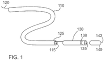
- FIG. 1 shows an exploded perspective view of several sections of a sheath of an example imaging probe 100 (e.g. a catheter) with a closed dome distal end and a deflectable tip.
- the elongate proximal section 110 has a main lumen 115, a generally circular cross section and a wall.
- There is a separate lumen 125 for a pull wire 120 which may have been constructed as is known in the art by including a separate piece of thin wall tubing, such as a polyimide tubing or as a multi-lumen extrusion.
- a softer distal section 130 with a generally softer material also has a main lumen 135 and a lumen for the pull wire 120.
- the pull wire 120 extends from the proximal end of the sheath, through the pull wire lumen 125 of the proximal section 110, through the pull wire lumen of the softer section 130 and is attached to the pull ring 138, such as by means of laser welding.
- the distal tip 140 is terminated by a distal dome 142, and is formed from a material having properties suitable for allowing the transmission of imaging energy through the wall of the distal tip 140.
- the distal tip 140 may be formed, for example, by a tip forming processes, a hot air station, or via injection molding.
- the material for the distal tip 140 may be selected for its properties such as mechanical strength, acoustic attenuation, optical clarity and others.
- the thickness of the wall of the distal tip 140 may also be designed with similar considerations.
- FIG. 2A shows a longitudinal sectional view of the walls of components of the sheath of the imaging probe 100 shown in FIG. 1 , namely the elongate proximal section 110, the softer section 130 and the distal tip 140.
- FIG. 2B shows the cross-section of the elongate proximal section 110
- FIG. 2C shows the cross-section of the portion of the softer distal section 130 where the pull ring 138 resides
- FIG. 2D shows a cross-section of the proximal portion of the distal tip 140.
- a mandrel that occupies the main lumen of the three sections, including the hollow portion of the distal tip 140, placing a heat shrink around the assembly, applying heat in a controlled manner and then removing the mandrel and heat shrink.
- a butt joint 150 is showing between the elongate proximal section 110 and the softer section 130.
- a lap joint 155 is showing between the softer section 130 and distal tip 140.
- proximal 110, softer 130 and distal tip 140 sections may be joined in discrete steps, incorporating the pull wire lumen 125 after the proximal 110 and softer 130 sections have been joined or adding braiding and an outer jacket to the proximal 110 and softer 130 sections.
- FIG. 3A shows the distal portion of the external sheath with a distal tip 140 and a pull wire 120 after the elongate proximal section, softer section and distal tip have been joined together at joints 155 and 150. If a user pulls on the proximal end of the pull wire 120 relative to the sheath, the side of the sheath on which the pull wire 120 resides will shorten and the softer section will deflect in that direction.
- FIG. 3B shows the advancement of a rotatable imaging conduit 160 (preferably a flexible torque cable) and a distal imaging assembly 170 (such as an ultrasound transducer) being advanced from the proximal end of the sheath towards the distal end.
- a rotatable imaging conduit 160 preferably a flexible torque cable
- a distal imaging assembly 170 such as an ultrasound transducer
- FIG. 3C shows the position of the rotatable imaging conduit 170 when the imaging assembly 170 is aligned with the distal tip 140, which acts as an imaging window for imaging energy, such as ultrasound waves or light, to travel between the imaging assembly 170 and a region exterior to the distal tip 140 of the catheter.
- imaging energy such as ultrasound waves or light
- an ultrasound transducer While it is desirable to minimize the cross-sectional area of the elongate section in order to be as minimally invasive as possible, it is in many cases desirable to maximize the size of a functional component within the device, such as an ultrasound transducer.
- a larger aperture ultrasound transducer tends to be more sensitive than a smaller aperture transducer.
- the ultrasound beam of a transducer tends to be better focused over a longer axial distance (i.e. along the axis of propagation of the ultrasound) with larger aperture sizes.
- imaging catheters such as those with complex scanning mechanisms as disclosed in US Patent Publication No. 20090264768
- several components of the imaging assembly may be sensitive to excessive heat, such as the insulation on electrical conductors, coatings, plastic housing components, epoxies, the imaging tip which often has a thin wall or other adhesive used in the assembly of the scanning mechanism etc.
- FIG. 4 An example embodiment of imaging catheter with an imaging assembly that addresses these problems is shown in FIG. 4 .
- the imaging assembly 170 is larger than the proximal section as shown in FIG. 4 and includes an imaging assembly 170 at the tip of the catheter that has a larger diameter than the main lumen 115 of the proximal section 110 attached to it.
- FIG. 4 shows an elongate proximal portion 110 bonded to the distal tip 140. It will be understood that the distal tip may instead be bonded to an intermediate sheath portion, as shown as the softer intermediate sheath portion in FIGS. 2-C and FIGS. 3A-C .
- the proximal sheath portion 110 may be made of a polyethylene extrusion, as well as distal tip 140, although any other medically graded plastics may alternatively be employed, provided that the two plastic extrusions are compatible with each other and can form a strong bond.
- the imaging assembly may be fully or partially rotatable.
- the imaging assembly 170 and rotatable imaging conduit 160, along with electrical leads, fiber optics, flush lumens and other components that reside within the portion of the rotatable imaging conduit 160 are inserted from the distal end of the sheath before the distal tip 140 is attached.
- Distal tip 140 is then placed on the proximal sheath portion 110 and the two plastics are bonded on the overlapped section 175 which is on top of a rigid reinforcing member 180.
- the rigid reinforcing member 180 may serve a dual purpose of the catheter design, such as the pull ring for a deflection mechanism and/or a marker band.
- the distal tip 140 is bonded to the proximal sheath portion 110 using heat shrink and the local application of heat.
- the rigid reinforcing member 180 acts in a manner similar to a mandrel by providing an outer radial force in the region 175 where the distal tip 140 and the proximal sheath portion 110 are compressed together by the heat shrink, which provides an inner radial force.
- the rigid reinforcing member 180 may be a separate hollow cylinder solely provided for this purpose.
- Low temperature heat shrink may be employed, where the low temperature heat shrink has a composition that shrinks at lower temperatures than the melting point of the plastic material forming the proximal sheath portion 110.
- polyolefin heat shrink tubing can be activated at approximately 90 degrees C compared to the melting temperature of Pebax 7233 that has a melting point of approximately 175 degrees Celsius.
- the heat shrink provides enough pressure to hold the entire assembly together. This process is not limited to the use of heat shrinks.
- Other instruments such as, but not limited to, a radial band, precision clamp, or other fixtures, can be used. Clear materials that pass laser energy therethrough can be used.
- other means of bonding regions may employed. Regions can be bonded using adhesives, such as cyanoacrylates, or various epoxies. Regions call also be joined with mechanical approaches such as press-fits, retaining pins or clips, etc.
- the overlapping region of the distal tip 140 and the proximal sheath portion 110 may be laser welded together, whereby the laser energy is localized to the joint region 175 such that the there is no collateral damage to the neighbouring parts of the catheter.
- a light absorbing material may be applied between the portions of the distal tip 140 and proximal sheath portion 110 that are to be joined together, in order to enhance the localization of the absorption of the light and thus localize the heat produced.
- the dome tip 140 is held in contact with the distal end of the sheath by heat shrink that allows the laser energy to pass therethrough. This process is not limited to the use of heat shrinks, and other instruments, such as a clear radial band, precision clear clamp made of glass or a polymer compatible with the laser energy or other fixtures that would pass the laser energy therethrough can be used.
- a light absorbing material may be used to absorb laser radiation from a YAG laser beam that passes through the top clear layer of plastic and produce heat at the intersection of the two plastic parts, thereby melting the plastic locally and bonding the two sections together.
- a YAG welding laser employs a YAG welding laser
- the present example process is not limited to utilizing a laser welder only.
- Other methods for bonding the joints with different inner diameters are for example using a focused hot air station that doesn't spread the heat much along the sheath, or using a hot iron, or other type of lasers such as diode lasers.
- thermoplastic extrusions or the use of suitable additives or pigments to the transparent plastics, such as carbon black.
- the rigid reinforcement member 180 can be used to provide structural support if the laser welding approach does not adequately localize the heat generated. Alternatively, the laser welding method may be performed in the absence of a rigid reinforcing member if the application of heat is adequately localized to the interface between distal 140 and proximal sheath portion 110.
- FIG. 5 shows an example embodiment in which a rigid reinforcement member 180 is placed over a mandrel 50, and where one end of a plastic extrusion is placed over the rigid reinforcement member 180.
- heat shrink is then placed on top of the assembly.
- a hot air station is used to melt the plastic extrusion 110 on top of the rigid reinforcement member 180. This results in a thin layer of plastic to cover a portion of the rigid reinforcement member 180 and to hold it in place at the distal end of the sheath.
- the heat shrink is then peeled off and the mandrel 50 is removed.
- a light-absorbing (e.g. Clearweld®) solution is then applied to the outer surface of the plastic sheath 110, on the portion that is on the rigid reinforcement member 180.
- the solution is given few minutes to dry.
- the proximal end of distal tip 140 is then placed on top of the rigid reinforcement member 180 and the distal end of extrusion 110, such that the overlapped section of the sheath 110 and the distal tip 140 are adequately overlap with the applied light absorbing solution.
- an overlapped bond could be made by having the distal end of the proximal section 110 on the outside layer and the proximal end of the distal tip 140 inside the distal end of the proximal section 110.
- the laser radiation is directed onto the overlapped section to bond the two layers.
- the laser beam passes through the first transparent layer and is absorbed at the intersection of the joint components, generating localized heat in return and creating an effective and reliable thermal bond.
- the overlapped section of the two plastic layers is located at or near the middle of the rigid reinforcement member 180, since directing a laser at the edge of the rigid reinforcement member 180 may result in melting and deformation of section of the plastic that is not supported by the rigid reinforcement member 180.
- this example process facilitates the fabrication of a catheter having a rotatable imaging conduit supporting an imaging assembly, where the imaging assembly is housed at or near the distal end of the catheter, and where the imaging assembly has a cross-sectional shape and size that is larger than what the lumen of the sheath would have otherwise accommodated by inserting the imaging assembly into the catheter sheath in a proximal to distal fashion.
- the imaging assembly can have a larger size than it otherwise would have according to the conventional proximal-to-distal insertion method.
- the wall of the sheath proximal to the distal tip can be made thicker and therefore can be made to include more functional components, as will be explained later.
- the distal section of the sheath may not need a separate rigid reinforcement member, as the sheath may have a thick enough wall thickness to withstand any inward radial forces applied by the heat shrink, and may also be thick enough to dissipate any localized heat used to create the thermal bond between the distal tip and section of the sheath 110 thus preventing the heat from deforming or otherwise damaging the catheter or its internal components.
- a pull wire and pull ring were included as components of the catheter to demonstrate that the inclusion of a feature such as a pull wire lumen along the elongate portion of the catheter requires space within the overall area of the cross-section of the elongate portion, thus limiting the size of the main lumen, and in turn, limiting the radial extent (size and shape) of an imaging assembly that is housed within the main lumen.
- many example embodiments of the present disclosure do not constrain the radial extent of the imaging assembly even in the presence of a pull-wire lumen.
- the cross section of the imaging portion of the distal tip may be designed to be larger than the cross-section of the main lumen by virtue of having a thinner wall thickness in the distal tip (for better imaging properties) than the wall surrounding the main lumen for of ease of manufacture, cost and / or structural integrity of the elongate portions of the catheter, such as the proximal elongate portion and the softer portion as in the exemplary embodiment.
- the imaging assembly may include more than an ultrasound transducer.
- the ultrasound transducer may be mounted on a housing and pivot assembly that allows the ultrasound transducer to pivot around a tilt access to enable 3D imaging, as disclosed in US Patent Publication No. 20090264768 .
- a 3D forward looking scanning mechanism may benefit from additional space in the distal tip of the catheter for the imaging assembly, where the additional space be used, for example, to accommodate a larger imaging assembly, which may then be used to make more room for components of the imaging assembly, including by not limited to a potentially larger ultrasound transducer than may otherwise be accommodated.
- the 3D scanning mechanism would preferably, but not necessarily, be located near the distal end of the catheter so that there is a relatively unobstructed line of sight free through the dome shaped imaging window, especially when the beam is emitted in a more forward-looking direction.
- the example methods of the present disclosure that permit the imaging assembly to be inserted from the distal end, allows the catheter be configured to have smaller inner lumen along its sheath. Such a smaller central lumen would allow for thicker wall diameter. This additional space may be employed, for example, to add off-centered lumens within the sheath.
- additional side lumens are the incorporation of additional pull wires that allow better maneuvering of the catheter. Maneuverability of catheters is especially important for ablation procedures, where the catheter is used to burn specific abnormal heart tissues that are arrhythmogenic sites within the atria and ventricles. In case of imaging catheters, this extra maneuverability allows for greater control of the field of view.
- Another use of side lumen is possibility of adding one or more flush lumens and/or one or more other fluid delivery lumens to the catheter.
- the additional cross-section space in the sheath that is made available by employing a central lumen that has a diameter this less than the lateral extent of the imaging assembly (or other distal functional device or element) can also or alternatively be used to insert or otherwise incorporate additional sensors into the catheter that are isolated from the central lumen, such as, but not limited to, temperature sensors, electromagnetic sensors for electro-anatomical mapping, fiber optics for rotary encoders (particularly synergistic as the reduced diameter of the torque cable might make the imaging system more susceptible to NURD) or pass through isolated wires attached to electrodes used for sensing intracardiac electrograms and/or cardiac pacing.
- additional sensors such as, but not limited to, temperature sensors, electromagnetic sensors for electro-anatomical mapping, fiber optics for rotary encoders (particularly synergistic as the reduced diameter of the torque cable might make the imaging system more susceptible to NURD) or pass through isolated wires attached to electrodes used for sensing intracardiac electrograms and/or cardiac pacing.
- the addition of many of these function-enhancing components may be preferred if the distalmost portion of the function-enhancing component is located proximal to the imaging assembly along the long (longitudinal) axis of the catheter.
- wires, fibers, and/or lumens used to enable the functionality of these components may interfere to a minimal or significant extent with the imaging performed by the imaging assembly if they were to cross the field of view of the imaging assembly.
- wires can cause shadowing in ultrasound imaging, so the aforementioned embodiments may be preferred for the case of ultrasound, but it may not be necessary for a pacing electrode and its associated wire to be located proximal to the imaging assembly.
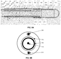
- FIGS. 6A and 6B show a distal section of the catheter that includes both a pose sensor 200 within the wall of sheath 110, wired electrically conductive conduits 205, torque cable (rotatable imaging conduit) 160, imaging distal tip 140, imaging assembly 170 and structurally rigid member 180.
- the structurally rigid member 180 is shown embedded in sheath 110, but in other example implementations (see, for example, FIG. 4 ), the structurally rigid member 180 can contact an inner surface of the sheath 110.
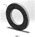
- fiber optic 210 also included to provide rotational encoding capabilities are fiber optic 210, optional imaging spacer 212 and optional lens 214 incorporated into the sheath, as well as encoding substrate 220 that rotates in unison with a rotating component such as the imaging assembly 170.
- a perspective view of the encoding substrate 220 is shown in FIG. 7 .
- the central circle in FIG. 6B shows an electrical coaxial cable 172 for delivering an ultrasound signal to and from the imaging assembly 170.
- a synergistic effect may be achieved by combining a smaller torque cable with a rotary encoder for detecting rotational motion.
- a smaller main lumen and smaller torque cable generally tends to negatively impact the rotational performance of the torque cable in terms of how closely the rotation of the proximal end of the torque cable translates into an equal amount of rotation of the distal end.
- a rotary encoder reduces the need for one-to-one transmission along the length of the torque cable. This relieves several design constraints of the rotating conduit and may allow a smaller and/or simpler design of torque cable, or even substitution of the torque cable with a simpler structure, such as a hollow polymer extrusion. Therefore, the rotary encoder enables a smaller diameter and potentially simpler torque transmission means, which in turn provides space within the wall of the catheter for the rotary encoder to be included in the catheter design.
- the pose sensor 200 may be, for example, one of those known in the art such as those supplied by NDI, Ascension Technology, or as found in a Carto system (Biosense Webster).
- NDI Ascension Technology
- Carto system Biosense Webster
- the advantage of including a pose sensor/emitter with an imaging catheter is well known in the art, as it provides coordinates within a reference coordinate system (typically a coordinate system that is referenced to a home position relative to a patient or the table on which the patient lies) as to where the images are being collected.
- a reference coordinate system typically a coordinate system that is referenced to a home position relative to a patient or the table on which the patient lies
- US Patent No. 6,443,894 provides an example of an imaging catheter that includes a pose sensor.
- Pose sensors have previously been incorporated onto array-based intracardiac echocardiography (ICE) catheters, where there is no rotational torque cable or rotary motor. Furthermore, the position and orientation of the images relative to the position and orientation of the pose sensor are more easily determined with an array-based imaging catheter, as there is a rather fixed geometric relationship between the pose sensor and the imaging array transducer. In a mechanical imaging catheter, the imaging transducer changes its position or orientation relative to the pose sensor. Therefore, in order to map the images from the imaging assembly onto the pose sensor reference frame, it is helpful to have a method of detecting the position and/or orientation of the imaging transducer.
- ICE intracardiac echocardiography
- a rotary encoder located external to the patient, coupled to a proximal portion of the torque cable (such as the rotary encoder in the patient interface module), provides some information about the rotational position of the imaging assembly.
- the precision of an external rotary encoder relative to the true rotational orientation within the sheath may not be accurate due to imprecision of the torque transmission provided by the torque cable, as it is an elongate and imperfect component that can be subject to artifacts such as non-uniform rotational distortion.
- the sheath in which the pose sensor is incorporated may be able to rotate freely relative to the rotating components within the catheter.
- the imaging assembly may be configured such that the angle at which the imaging beam is emitted is tiltable into more forward or side viewing directions, and there may be a tilt angle encoder provided, such as those described in US Patent Application Publication No. 20120197113 .
- a rotational encoder 220 between the imaging assembly and the sheath, such as that included in FIG. 6A . It may similarly be desirable to incorporate a tilt angle encoder within the imaging assembly or sheath, such as those described in US Patent Application Publication No. 20120197113 and US Patent No. 8,712,506 .
- a magnet-based pose emitter located on a rotational IVUS catheter has been built by Mediguide (owned by St. Jude), where there is a small magnet placed on the tip of an IVUS catheter to enable sensing of the position of the IVUS catheter tip.
- the Mediguide magnet does not require wires along the length of the catheter, and therefore there is no imaging artifact created by the addition of a Mediguide magnet to the catheter tip from any wires that would normally be associated with several other embodiments of a pose sensor or emitter.
- NDI supplies pose sensors that are less than 1 mm in diameter and less than a centimeter in length that can detect the position and orientation in either 5 or 6 degrees of freedom.
- pose sensors can enable the detection of the 3D position within a reference coordinate system (e.g. x,y,z), as well as two or 3 angular orientations of the sensor.
- the roll axis of the orientation e.g. rotational orientation around an axis of the sensor, such as the long axis of the sensor
- the NDI system works by having a field generator placed near the patient that creates an electromagnetic field over the patient.
- the sensor includes one or more coils and associated wiring that detect the local electromagnetic field and transmit the signal(s) to a console along the associated wiring to a processing unit to determine the position and / or orientation of the sensor.
- the field may be either a static magnetic field or a time-varying electromagnetic field.
- a commonly used system employs a time-varying electromagnetic field to achieve position and orientation sensing.
- Another form of position sensing involves the use of electric impedance measurement through the body to triangulate the position of an electrode that is in contact with the anatomy.
- This system usually has two or more (usually at least three) reference electrodes or electrode patches attached to the body from which the catheter electrode positions are triangulated or otherwise estimated.
- two sensors where one sensor has five degree-of-freedom (DOF) sensing and the other sensor has at least position sensing at roughly the same longitudinal position on the catheter can be employed to provide the information needed to determine the sixth degree of freedom (roll) if the two sensors are positioned relative to each other in a known configuration.
- An advantage of using two sensors to provide six degrees of positioning and orientation, rather than a single six DOF sensor is that the two sensors (in and of themselves that are less than six DOF) may each might be smaller than a six DOF sensor.
- a large single sensor might force the main lumen to be smaller than what two smaller sensors positioned at two different places around the main lumen might require.
- Electromagnetic sensors may be more accurate and precise than a simple electrode.
- a pose sensor to a mechanical scanned imaging catheter has several advantages. It makes it easier for the user to understand the relationship of the maneuvers applied to the catheter (made by the user or an actuator such as a robotic mechanism outside of the body) to the position and orientation relative to the reference frame. It allows the imaging data to be mapped to a 3D or 4D (3D + time, such as ECG-gated time windows) dataset and if Doppler is enabled, a 5D dataset (3D + time + flow). Furthermore, image quality with imaging catheters is dependent on several aspects of the catheter.
- Imaging data acquired within a preferred region where the imaging beams are more focused, such as in the near field of a single element of a single element ultrasound transducer (as opposed to an array transducer) generally has better quality than imaging data outside of that region. Therefore, by moving the distal portion of the imaging catheter within the body, some imaging data will be of better quality as the catheter moves closer to the tissue of interest.
- 3D or 4D imaging data that was acquired outside of the preferred region can be updated with the imaging data that is later acquired within a preferred or optimal region to improve the overall quality of the dataset.
- ultrasound image quality can be somewhat dependent on the angle of incidence between the ultrasound beam and the structures imaged. Therefore, in some example embodiments, images may be obtained of the same structure from multiple viewpoints, and the approximate angle of incidence may be estimated using segmentation algorithms known in the art. For example, often optimal imaging signal is at normal incidence. In some cases, at normal incidence, reverberation artifacts are present and it is preferred to be near normal incidence, but off by a small amount (approximately 3-10 degrees). The imaging data that was collected with the most preferred angles of incidence may be employed to create the 3D or 4D composite imaging data sets.
- ultrasound image quality can be somewhat dependent on the distance between the ultrasound transducer and the structures being imaged.
- the transducer is a focused transducer
- optimal imaging will occur within the focal region.
- the focal region is often defined as the full width half maximum (FWHM) region along the depth direction along a given A-scan line.
- FWHM full width half maximum
- Approximate distance may be estimated using segmentation algorithms known in the art.
- the imaging data that was collected with the most preferred distance may be employed to create the 3D or 4D composite imaging data sets.
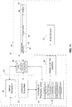
- FIG. 10 a flow chart is shown the illustrates such an example method, in which the computed angle of incidence and/or proximity associated with image data is employed to selectively update a 3D image.
- a 3D or 4D image data set is initially acquired, as shown at 400, and a 3D representation is reconstructed from the data set, as shown at 410, using information provided by the POSE sensor.
- Additional incremental imaging data is then acquired, which may be 2D, 3D or 4D, as shown at 420.
- POSE information the incremental image data is processed to determine if it corresponds, at least in part, to previously acquired image data, as shown at 430.
- the POSE information is then employed to determine, at step 440 an angle of incidence and/or proximity information associated with the incremental imaging data.
- the insertable portion is configured to be flexible, especially when advanced into the vasculature, which has some tortuosity to it. Accordingly, if the rigid reinforcement member 180 is too long, it will make produce local stiffness that is undesirable.
- the length of the rigid member may be less than 20 times the outer diameter of the probe, less than 10 times the outer diameter of the probe, less than 5 times the outer diameter of the probe, less than 3 times the outer diameter of the probe or less than 1 times the outer diameter of the probe.
- FIG. 8 shows an example embodiment in which the distal region of a catheter sheath incorporates a winding 240 that surrounds the main lumen.
- the winding may be in electrical communication with external electronics via electrically conductive conduits 245.
- the example winding shown in FIG. 8 could be used for several applications, such as, but not limited to:
- a potential advantage of providing a POSE sensor that surrounds the main lumen 115 (as in FIG. 8 ) as opposed to adjacent to the main lumen 115 (as in FIG. 6A ) is that it such a configuration may accommodate a larger main lumen than the embodiment of FIG. 6A , and may enable a more radially symmetric design.
- FIG. 9 An example implementation in which the winding 240 is capable of actuating motion within the probe involves the incorporation of a magnet within the backing of a tiltable transducer.
- FIG. 9 An example of such an embodiment is shown in FIG. 9 , where the tiltable transducer 260 tilts around a pivot axis 265 and is pivotally mounted to a shell 270, where the tiltable transducer 260 has a magnet 280 attached thereto, recessed therein, or otherwise mechanically supported.
- the ultrasound transducer 260 is connected via conductive springs (not shown) to one or more electrical signal conduits (not shown) within the torque cable.
- a magnetic field can be generated that tilts tiltable transducer 260 via attractive / repelling forces between the transducer magnet 280 and the winding 240.
- the magnet 280 does not need to necessarily be attached directly to the transducer 260.
- the magnet could be attached to a push rod or shaft to cause a transducer within the imaging assembly to tilt or translate.
- the winding conduits 245 are typically electrically insulated from each other and, either supplied with insulation or insulated as a result of their incorporation into the catheter wall.
- the winding conduits 245 could be incorporated into a reinforcement braiding in the sheath to reduce the use of cross-sectional area along the main portion of the sheath.
- the distal tip region may be configured to include multiple transducers supported by one or more imaging assemblies, where the imaging assemblies and/or transducers have a lateral extent that is larger than the inner diameter of the main lumen of the catheter.
- distal tip described and shown herein which includes a distal dome-shaped profile, provides a non-limiting example of a distal tip configuration, and that other distal tip geometries and profiles may be employed without departing from the intended scope of the present disclosure.
- distal tip may include one or more openings or ports.
- an imaging system comprising imaging probe 44, which connects via patient interface module 36 to image processing and display system 49.
- Image processing and display system 49 includes hardware to support one or more imaging modalities, such as ultrasound, optical coherence tomography, angioscopy, infrared imaging, near infrared imaging, Raman spectroscopy-based imaging, or fluorescence imaging.
- imaging modalities such as ultrasound, optical coherence tomography, angioscopy, infrared imaging, near infrared imaging, Raman spectroscopy-based imaging, or fluorescence imaging.
- Specific embodiments of ultrasonic imaging probes and combined ultrasonic and optical imaging probes are disclosed by Courtney et al. in US Patent Publication No. 20080177183 , titled “Imaging Probe with Combined Ultrasounds and Optical Means of Imaging” and filed on January 22, 2008 , US Patent Publication No. 20080177138 , titled “Scanning Mechanisms for Imaging Probe” and filed on January 22, 2008 and US Patent Publication No.
- Controller and processing unit 34 is employed to facilitate the coordinated activity of the many functional units of the system, and may contain some or all of the components shown in the Figure and listed herein. Controller and processing unit 34, or a separate computing device or system, may also be employed to implement the methods associated with the flow chart shown in FIG. 10 .
- An operator interacts with system 50 via display and/or user interface 38.
- System 10 may further include electrode sensors 40 to acquire electrocardiogram signals from the body of the patient being imaged.
- the electrocardiogram signals may be used to time the acquisition of imaging data in situations where cardiac motion may have an impact on image quality.
- the electrocardiogram may also serve as a trigger for when to begin an acquisition sequence, such as when to begin changing the speed of rotation of a motor in order to cause a desired scan pattern to take effect.
- electrocardiogram triggered initiation of an imaging sequence may enable images to be acquired during a particular phase of the cardiac cycle, such as systole or diastole.
- Optical subsystem 30, if included in a particular implementation of an imaging system may include any or all of the following components: interferometer components, one or more optical reference arms, optical multiplexors, optical demultiplexers, light sources, photodetectors, spectrometers, polarization filters, polarization controllers, timing circuitry, analog to digital converters, parallel processing arrays and other components known to facilitate any of the optical imaging techniques.
- Ultrasound subsystem 32 may include any or all of the following components: pulse generators, electronic filters, analog to digital converters, parallel processing arrays, envelope detectors, amplifiers including time gain compensation amplifiers and other components known to facilitate acoustic imaging techniques.
- Controller and processing units 34 if included in a particular implementation of the imaging system, serve multiple purposes. Those skilled in the art will appreciate that specific components required depend on the needs of a particular type of imaging system.
- controller and processing units may include any combination of a motor drive controller, data storage components (such as memory, hard drives, removable storage devices, readers and recorders for media such as CDs, DVDs, and BlurayTM discs), position sensing circuitry and/or software, angle detection circuitry and/or software, timing circuitry and/or software, cardiac gating functionality, volumetric imaging processors, scan converters and others.
- display and user interface 38 is also optionally provided for either real time display or display of data at a time later than the time at which imaging data is acquired.
- patient interface module 36 and controller and processing units 34 are but one example illustration of the selection and organization of hardware subsystems, and that many other implementations are possible.
- patient interface module 36 may be housed with controller and processing units 34 within processing and display system 49.
- Example imaging probe 44 includes an imaging assembly 50, optional imaging conduit 46 along a substantial portion of its length, and connector 48 at its proximal end 47.
- Imaging assembly 50 is located near distal end 41 of imaging probe 44.
- Imaging assembly 50 generally refers to the components of the imaging probe 44 from which the signals (either acoustic, optical or both) are collected for the purposes of imaging a region that is proximate to imaging assembly 50.
- Imaging assembly 50 may house transducers for transmitting and/or receiving imaging radiation.
- the emitter and receiver may be a single component, as is often the case with a piezoelectric transducer.
- imaging assembly 50 typically contains the distal tip of a fiber optic, as well as a combination of optical components such as a lens (for instance, a ball lens or a GRIN lens).
- a mirror and/or prism may be included for use in beam delivery and/or collection.
- Imaging probe 44 may contain ports at one or more points along its length to facilitate flushing.
- imaging assembly 50, connector 48 and/or imaging conduit 46 may be filled and / or surrounded with a fluid such as saline, and may be flushed.
- imaging probe 44 may be filled with a gas.
- the gas may include carbon dioxide or another readily dissolved gas with minimal biotoxicity.
- imaging assembly 50 may be compartmentalized to include at least one gas-filled compartment or lumen for optical imaging and at least one fluid filled compartment or chamber for acoustic imaging.
- Imaging conduit 46 includes at least one conductive wire (optionally two or more) that connect an emitter and/or receiver via connection to an adapter, herein referred to as patient interface module 36.
- Imaging conduit 46 may include a fiber optic, for example, wrapped by two layers of electrical wire that are electrically insulated from one another. Imaging conduit 46 may further be reinforced by other structural features, such as helically wrapped wires or other designs used to construct imaging torque cables for rotating scan mechanisms.
- imaging conduit 46 may contain electrical conductors, and a rotational mechanism may be located remote from the proximal end for imparting rotary motion to the imaging assembly.
- One example mechanism includes a micro-motor and a slip ring in close proximity to the imaging assembly.
- the imaging probe 44 may optionally include memory, such as an EEPROM for storing information including calibration information, serial information, probe design information, desired filter information, and any other probe specific information. This memory may reside in connector 48.
- memory such as an EEPROM for storing information including calibration information, serial information, probe design information, desired filter information, and any other probe specific information. This memory may reside in connector 48.
- Patient interface module 36 facilitates transmission of signals within any fibers and/or wires to the appropriate image processing units. It may contain a motor drive unit for imparting rotational motion to the components of the imaging mechanism. Additional sensors may be incorporated as part of patient interface module 36, such as position sensing circuitry, for example, to sense the angle of rotation of a rotary component within the imaging probe 44 and/or for detecting the angle of deflection of a member at the distal end 41 of the imaging probe 44. Additionally, patient interface module 36 may include amplifiers to improve the transmission of electrical signals or power between the imaging probe 44 and the rest of the system.
Landscapes
- Health & Medical Sciences (AREA)
- Life Sciences & Earth Sciences (AREA)
- Surgery (AREA)
- Physics & Mathematics (AREA)
- Engineering & Computer Science (AREA)
- Biomedical Technology (AREA)
- Veterinary Medicine (AREA)
- Heart & Thoracic Surgery (AREA)
- Medical Informatics (AREA)
- Molecular Biology (AREA)
- Animal Behavior & Ethology (AREA)
- General Health & Medical Sciences (AREA)
- Public Health (AREA)
- Pathology (AREA)
- Biophysics (AREA)
- Nuclear Medicine, Radiotherapy & Molecular Imaging (AREA)
- Radiology & Medical Imaging (AREA)
- Optics & Photonics (AREA)
- Vascular Medicine (AREA)
- Cardiology (AREA)
- Spectroscopy & Molecular Physics (AREA)
- Electromagnetism (AREA)
- Otolaryngology (AREA)
- Physiology (AREA)
- Microelectronics & Electronic Packaging (AREA)
- Ultra Sonic Daignosis Equipment (AREA)
- Endoscopes (AREA)
Claims (11)
- Procédé d'assemblage d'une sonde d'imagerie, le procédé comprenant :l'utilisation d'une gaine allongée (110) ayant une lumière interne (115) et une ouverture distale, un élément de renforcement rigide (180) étant fixé à une surface interne de ladite gaine allongée ou étant noyé en son sein dans la région distale de ladite gaine allongée ;l'insertion, à travers l'ouverture distale de la gaine allongée, d'un conduit rotatif (160) ayant un ensemble d'imagerie (170) connecté à une extrémité distale du conduit rotatif, une étendue latérale de l'ensemble d'imagerie étant supérieure au diamètre de la lumière interne de la gaine allongée, de sorte que l'ensemble d'imagerie s'étende depuis l'ouverture distale de la gaine allongée ;l'utilisation d'une pointe distale (140) ayant une extrémité distale et une extrémité proximale ouverte ;l'insertion de la pointe distale sur l'ensemble d'imagerie, de telle sorte que la partie proximale de la pointe distale entre en contact avec la gaine allongée et la chevauche sur une région de contact (175) qui est adjacente à l'élément de renforcement rigide ; etla fixation de la pointe distale à la gaine allongée, la fixation étant effectuée par application locale de chaleur sur la région de contact.
- Procédé selon la revendication 1, dans lequel l'élément de renforcement rigide est inséré dans l'ouverture distale de la gaine allongée de telle sorte que l'élément de renforcement rigide s'étende dans une direction distale par rapport à l'ouverture distale de la gaine allongée.
- Procédé selon la revendication 1 ou 2, dans lequel la pointe distale est fixée à la gaine allongée par soudage au laser.
- Procédé selon la revendication 3, dans lequel un milieu absorbant optique est placé entre la partie proximale de la pointe distale et la gaine allongée.
- Sonde d'imagerie comprenant :une gaine allongée (110) ayant une lumière interne (115) et une ouverture distale, un élément de renforcement rigide (180) est fixé à une surface interne de ladite gaine allongée ou étant noyé en son sein dans la région distale de ladite gaine allongée ;un conduit rotatif (160) s'étendant à travers ladite lumière interne, ledit conduit rotatif ayant un ensemble d'imagerie (170) connecté à son extrémité distale, une étendue latérale dudit ensemble d'imagerie étant supérieure au diamètre de ladite lumière interne de ladite gaine allongée de sorte qu'au moins une partie dudit ensemble d'imagerie se trouve distalement par rapport à l'extrémité distale de ladite gaine allongée ;une pointe distale (140) logeant ledit ensemble d'imagerie, une partie proximale de la pointe distale étant fixée à une région distale de ladite gaine allongée sur une région de contact (175) qui est adjacente à l'élément de renforcement rigide.
- Sonde d'imagerie selon la revendication 5, dans laquelle ledit élément de renforcement rigide est une bague de traction (138) pour un mécanisme de déviation.
- Sonde d'imagerie selon la revendication 5, dans laquelle ledit élément de renforcement rigide est une bande de repérage.
- Sonde d'imagerie selon l'une quelconque des revendications 5 à 7, dans laquelle ladite gaine allongée comprend une pluralité de lumières latérales.
- Sonde d'imagerie selon la revendication 8, dans laquelle une ou plusieurs desdites lumières latérales comprennent au moins une partie d'un mécanisme de détection.
- Sonde d'imagerie selon la revendication 8, dans laquelle une ou plusieurs desdites lumières latérales comprennent un capteur de pose (200).
- Sonde d'imagerie selon la revendication 5, dans laquelle une étendue longitudinale dudit élément de renforcement rigide est inférieure à un diamètre extérieur de ladite sonde d'imagerie.
Applications Claiming Priority (2)
| Application Number | Priority Date | Filing Date | Title |
|---|---|---|---|
| US201662300583P | 2016-02-26 | 2016-02-26 | |
| PCT/CA2017/050248 WO2017143457A1 (fr) | 2016-02-26 | 2017-02-27 | Sonde d'imagerie avec noyau rotatif |
Publications (3)
| Publication Number | Publication Date |
|---|---|
| EP3419507A1 EP3419507A1 (fr) | 2019-01-02 |
| EP3419507A4 EP3419507A4 (fr) | 2019-09-11 |
| EP3419507B1 true EP3419507B1 (fr) | 2021-06-30 |
Family
ID=59684840
Family Applications (1)
| Application Number | Title | Priority Date | Filing Date |
|---|---|---|---|
| EP17755694.1A Active EP3419507B1 (fr) | 2016-02-26 | 2017-02-27 | Sonde d'imagerie avec noyau rotatif |
Country Status (7)
| Country | Link |
|---|---|
| US (3) | US11317891B2 (fr) |
| EP (1) | EP3419507B1 (fr) |
| JP (2) | JP6923545B2 (fr) |
| KR (1) | KR102755164B1 (fr) |
| CN (2) | CN109068995B (fr) |
| CA (1) | CA3015404A1 (fr) |
| WO (1) | WO2017143457A1 (fr) |
Families Citing this family (40)
| Publication number | Priority date | Publication date | Assignee | Title |
|---|---|---|---|---|
| KR101903074B1 (ko) * | 2016-08-24 | 2018-10-01 | 울산과학기술원 | 회전형 동축 광-전자기 도파관 집합체를 포함하는 광음향-초음파 내시경 시스템과 그 구현 방법 |
| US11331074B2 (en) | 2017-09-15 | 2022-05-17 | Infraredx, Inc. | Method of using an imaging catheter with a reinforced section |
| CN111432732B (zh) * | 2017-12-07 | 2024-10-29 | 皇家飞利浦有限公司 | 用于腔内成像装置的柔性尖端及相关装置、系统和方法 |
| WO2019213594A1 (fr) * | 2018-05-03 | 2019-11-07 | The General Hospital Corporation | Systèmes, procédés et supports pour endoscopie multimode basée sur une capsule |
| US12507984B2 (en) | 2019-01-07 | 2025-12-30 | Philips Image Guided Therapy Corporation | Strain relief for intraluminal ultrasound imaging and associated devices, systems, and methods |
| JP7539900B2 (ja) * | 2019-01-29 | 2024-08-26 | キヤノン ユーエスエイ,インコーポレイテッド | 遠位端付近のエンコーダからの回転位置のリアルタイム信号を用いたイメージング再構成 |
| WO2020181280A1 (fr) * | 2019-03-07 | 2020-09-10 | Procept Biorobotics Corporation | Gaine rigide de sonde d'imagerie |
| CN109946786A (zh) * | 2019-03-25 | 2019-06-28 | 北京大学口腔医学院 | 一种可控自变形光纤的多功能激光手术刀和激光加工设备 |
| US20220175256A1 (en) * | 2019-04-25 | 2022-06-09 | Opsens, Inc. | Guidewire with internal pressure sensor |
| CN110115599B (zh) * | 2019-05-16 | 2021-09-24 | 声索生物科技(上海)有限公司 | 鞘管组件、超声探头及其组装方法 |
| US11931073B2 (en) * | 2019-05-17 | 2024-03-19 | Boston Scientific Scimed, Inc. | Medical imaging devices, systems, and methods |
| CN110587996A (zh) * | 2019-09-09 | 2019-12-20 | 江苏美安医药股份有限公司 | 两个间隙配合产品的激光焊接方法 |
| CN113318324B (zh) | 2020-02-28 | 2026-05-12 | 巴德阿克塞斯系统股份有限公司 | 具有光学形状感测能力的导管 |
| WO2021173861A1 (fr) | 2020-02-28 | 2021-09-02 | Bard Access Systems, Inc. | Systèmes de connexion optique et procédés associés |
| WO2021178578A1 (fr) | 2020-03-03 | 2021-09-10 | Bard Access Systems, Inc. | Système et procédé de détection de forme optique et de conduction de signal électrique |
| CN115209827A (zh) * | 2020-03-10 | 2022-10-18 | 圣犹达医疗用品心脏病学部门有限公司 | 具有集成的电子封装体的导管尖端和包含其的导管 |
| US11931179B2 (en) | 2020-03-30 | 2024-03-19 | Bard Access Systems, Inc. | Optical and electrical diagnostic systems and methods thereof |
| US11899249B2 (en) | 2020-10-13 | 2024-02-13 | Bard Access Systems, Inc. | Disinfecting covers for functional connectors of medical devices and methods thereof |
| CN216558785U (zh) | 2020-11-18 | 2022-05-17 | 巴德阿克塞斯系统股份有限公司 | 光纤管心针保持器 |
| WO2022115624A1 (fr) | 2020-11-24 | 2022-06-02 | Bard Access Systems, Inc. | Instrument médical allongé activé par détection de forme de fibre optique orientable |
| US11730548B2 (en) | 2020-12-17 | 2023-08-22 | Industrial Technology Research Institute | Optical coherence tomography scanning probe |
| CN113171185A (zh) * | 2021-04-26 | 2021-07-27 | 吉林大学 | 一种磁力引导的肠道病变标记物微创探测追踪及位置锁定装置 |
| CN115813547A (zh) | 2021-09-16 | 2023-03-21 | 巴德阿克塞斯系统股份有限公司 | 连接部件和执行医疗操作的方法 |
| JP2024546080A (ja) * | 2021-12-02 | 2024-12-17 | エンスペクトラ・ヘルス・インコーポレイテッド | 光操作のためのシステム及び方法 |
| US12318149B2 (en) | 2022-03-08 | 2025-06-03 | Bard Access Systems, Inc. | Medical shape sensing devices and systems |
| US12426956B2 (en) | 2022-03-16 | 2025-09-30 | Bard Access Systems, Inc. | Medical system and method for monitoring medical device insertion and illumination patterns |
| US12089815B2 (en) * | 2022-03-17 | 2024-09-17 | Bard Access Systems, Inc. | Fiber optic medical systems and devices with atraumatic tip |
| US12605116B2 (en) | 2022-04-11 | 2026-04-21 | Bard Access Systems, Inc. | Fiber optic medical systems and devices with electrical tip |
| US12575893B2 (en) | 2022-06-24 | 2026-03-17 | Bard Access Systems, Inc. | Shape sensing fiber optic tip protection systems and devices |
| US12564340B2 (en) | 2022-07-12 | 2026-03-03 | Bard Access Systems, Inc. | Eccentric single-core fiber-optic enabled medical device |
| US20240023929A1 (en) * | 2022-07-20 | 2024-01-25 | SoundCath, Inc. | Ultrasonic catheter |
| CN115299996A (zh) * | 2022-08-16 | 2022-11-08 | 苏州大学附属第二医院 | 一种用于内窥镜的超声探头、脊柱内镜组件及超声设备 |
| JP2024051351A (ja) * | 2022-09-30 | 2024-04-11 | テルモ株式会社 | 画像処理装置、画像表示システム、画像表示方法、及び画像処理プログラム |
| US12599360B2 (en) | 2022-10-24 | 2026-04-14 | Boston Scientific Scimed, Inc. | Ultrasonic imaging ablation catheter system and method |
| US12622670B2 (en) | 2023-02-08 | 2026-05-12 | Boston Scientific Scimed, Inc. | Integrated cardiac mapping and piezoelectric micromachined ultrasonic transducer (pMUT) ultrasonic imaging catheter system and method |
| US12599361B2 (en) | 2023-02-14 | 2026-04-14 | Boston Scientific Scimed, Inc. | Ultrasonic imaging system and method |
| CN117357152A (zh) * | 2023-11-06 | 2024-01-09 | 深圳心寰科技有限公司 | 前视机械四维心腔内超声成像系统 |
| WO2025117703A1 (fr) * | 2023-11-27 | 2025-06-05 | Worcester Polytechnic Institute | Imagerie à tolérance magnétique |
| WO2025221036A1 (fr) * | 2024-04-19 | 2025-10-23 | 울산과학기술원 | Microscope photoacoustique ultra-miniature |
| WO2026077845A1 (fr) * | 2024-10-10 | 2026-04-16 | Koninklijke Philips N.V. | Cathéter d'échographie intracardiaque avec capteur électromagnétique intégré |
Family Cites Families (62)
| Publication number | Priority date | Publication date | Assignee | Title |
|---|---|---|---|---|
| US4142592A (en) | 1973-05-25 | 1979-03-06 | N.V. Raychem S.A. | Repairable assembly for protecting a cable junction and method of assembling same |
| US4794931A (en) | 1986-02-28 | 1989-01-03 | Cardiovascular Imaging Systems, Inc. | Catheter apparatus, system and method for intravascular two-dimensional ultrasonography |
| JP2751173B2 (ja) | 1988-01-26 | 1998-05-18 | 松下電器産業株式会社 | 画像表示装置用真空容器 |
| US4905698A (en) * | 1988-09-13 | 1990-03-06 | Pharmacia Deltec Inc. | Method and apparatus for catheter location determination |
| NL8901084A (nl) * | 1989-04-28 | 1990-11-16 | Du Med Bv | Intra-luminale inrichting. |
| US5108411A (en) * | 1990-03-28 | 1992-04-28 | Cardiovascular Imaging Systems, Inc. | Flexible catheter drive cable |
| US5178150A (en) * | 1991-02-25 | 1993-01-12 | Silverstein Fred E | Miniature ultrasound imaging probe |
| US5373845A (en) | 1992-05-22 | 1994-12-20 | Echo Cath, Ltd. | Apparatus and method for forward looking volume imaging |
| JPH07155327A (ja) * | 1993-12-03 | 1995-06-20 | Terumo Corp | 体腔内超音波プローブ |
| US5427107A (en) * | 1993-12-07 | 1995-06-27 | Devices For Vascular Intervention, Inc. | Optical encoder for catheter device |
| JP3248344B2 (ja) * | 1994-04-07 | 2002-01-21 | 富士写真光機株式会社 | 体内挿入型超音波診断装置 |
| US5569221A (en) | 1994-07-07 | 1996-10-29 | Ep Technologies, Inc. | Catheter component bond and method |
| CN2223112Y (zh) * | 1995-01-08 | 1996-03-27 | 王共先 | 一种专治宫颈疾病的腔内射频电极导管 |
| US5727553A (en) * | 1996-03-25 | 1998-03-17 | Saad; Saad A. | Catheter with integral electromagnetic location identification device |
| JPH10230016A (ja) * | 1996-12-18 | 1998-09-02 | Masahiro Ogami | 医療器具の位置検出方法と、それに用いる医療器具セットと、それらに使用する医療器具、医療器具先端位置検出用部材及び医療器具先端位置検出装置 |
| JP3525700B2 (ja) * | 1997-09-24 | 2004-05-10 | 富士写真光機株式会社 | 超音波プローブ |
| US6443894B1 (en) | 1999-09-29 | 2002-09-03 | Acuson Corporation | Medical diagnostic ultrasound system and method for mapping surface data for three dimensional imaging |
| US6394956B1 (en) * | 2000-02-29 | 2002-05-28 | Scimed Life Systems, Inc. | RF ablation and ultrasound catheter for crossing chronic total occlusions |
| JP2003052696A (ja) * | 2001-08-20 | 2003-02-25 | Fuji Photo Optical Co Ltd | 回転式超音波プローブ |
| US6891984B2 (en) * | 2002-07-25 | 2005-05-10 | Lightlab Imaging, Llc | Scanning miniature optical probes with optical distortion correction and rotational control |
| US7575568B2 (en) * | 2003-12-10 | 2009-08-18 | Boston Scientific Scimed, Inc. | Catheter distal tip |
| AU2005228956B2 (en) | 2004-03-23 | 2011-08-18 | Boston Scientific Limited | In-vivo visualization system |
| JP4668592B2 (ja) * | 2004-11-25 | 2011-04-13 | オリンパス株式会社 | 体腔内プローブ装置 |
| US7666143B2 (en) * | 2004-12-14 | 2010-02-23 | Siemens Medical Solutions Usa, Inc. | Array rotation for ultrasound catheters |
| US7621874B2 (en) | 2004-12-14 | 2009-11-24 | Scimed Life Systems, Inc. | Systems and methods for improved three-dimensional imaging of a body lumen |
| US20060182907A1 (en) * | 2005-02-11 | 2006-08-17 | Boston Scientific Scimed, Inc. | Novel microfibrillar reinforced polymer-polymer composites for use in medical devices |
| US20070167821A1 (en) | 2005-11-30 | 2007-07-19 | Warren Lee | Rotatable transducer array for volumetric ultrasound |
| US7867169B2 (en) | 2005-12-02 | 2011-01-11 | Abbott Cardiovascular Systems Inc. | Echogenic needle catheter configured to produce an improved ultrasound image |
| US7794393B2 (en) * | 2006-04-13 | 2010-09-14 | Larsen Dane M | Resectoscopic device and method |
| US20070260222A1 (en) * | 2006-05-08 | 2007-11-08 | Kraus Robert G | Catheter having reinforcing rings and method of use |
| CN103222846B (zh) | 2007-01-19 | 2017-04-26 | 桑尼布鲁克健康科学中心 | 用于成像探头的扫描机构 |
| US8460195B2 (en) | 2007-01-19 | 2013-06-11 | Sunnybrook Health Sciences Centre | Scanning mechanisms for imaging probe |
| JP2008188304A (ja) * | 2007-02-06 | 2008-08-21 | Terumo Corp | 医療用カテーテル |
| WO2008111070A2 (fr) * | 2007-03-12 | 2008-09-18 | David Tolkowsky | Dispositifs et procédés pour effectuer des opérations médicales dans des structures luminales arborescentes |
| US8317711B2 (en) | 2007-06-16 | 2012-11-27 | St. Jude Medical, Atrial Fibrillation Division, Inc. | Oscillating phased-array ultrasound imaging catheter system |
| US20130165945A9 (en) * | 2007-08-14 | 2013-06-27 | Hansen Medical, Inc. | Methods and devices for controlling a shapeable instrument |
| US8226641B2 (en) * | 2007-12-21 | 2012-07-24 | St. Jude Medical, Atrial Fibrillation Division, Inc. | Medical catheter with deflection pull ring and distal tip attachment apparatus |
| US8162934B2 (en) | 2007-12-21 | 2012-04-24 | St. Jude Medical, Atrial Fibrillation Division, Inc. | Medical catheter assembly with deflection pull ring and distal tip interlock |
| CN102231965B (zh) | 2009-11-17 | 2014-03-12 | 奥林巴斯医疗株式会社 | 活检辅助系统 |
| CN103228198B (zh) * | 2010-09-08 | 2016-07-06 | 科维蒂恩有限合伙公司 | 具有成像组件的导管 |
| AU2011319740B9 (en) * | 2010-10-27 | 2015-09-24 | W. L. Gore & Associates, Inc. | Imaging catheter with rotatble array |
| CA3085777C (fr) | 2010-11-08 | 2022-03-15 | Conavi Medical Inc. | Systemes et procedes pour ameliorer la visualisation lors d'interventions minimalement invasives |
| CN102563272A (zh) * | 2010-12-15 | 2012-07-11 | 林青宣 | 防止塑料管接头热熔缺陷的金属固定挡板 |
| US10524765B2 (en) | 2010-12-27 | 2020-01-07 | St. Jude Medical, Atrial Fibrillation Division, Inc. | Refinement of an anatomical model using ultrasound |
| DE102011009866B4 (de) * | 2011-01-31 | 2013-09-05 | Heraeus Precious Metals Gmbh & Co. Kg | Direkt aufbringbare elektrische Durchführung |
| US9402975B2 (en) * | 2011-08-31 | 2016-08-02 | Becton, Dickinson And Company | Systems and methods to increase rigidity and snag-resistance of catheter tip |
| JP5399589B2 (ja) | 2011-10-31 | 2014-01-29 | オリンパスメディカルシステムズ株式会社 | 医療機器 |
| CN103957983B (zh) * | 2011-11-25 | 2016-10-26 | 泰尔茂株式会社 | 医疗用管和导管 |
| CN103252014B (zh) * | 2012-02-17 | 2016-12-14 | 株式会社戈德曼 | 医疗用器具 |
| CN202469290U (zh) * | 2012-03-16 | 2012-10-03 | 浙江富亿管业有限公司 | 防漏管件 |
| CN202682499U (zh) * | 2012-04-26 | 2013-01-23 | Et视觉有限公司 | 支气管导管 |
| US9717475B2 (en) * | 2012-05-11 | 2017-08-01 | Volcano Corporation | Ultrasound catheter for imaging and blood flow measurement |
| AU2013371494B2 (en) * | 2013-01-04 | 2017-01-05 | Muffin Incorporated | Ultrasound transducer direction control |
| CN103071230B (zh) * | 2013-01-28 | 2014-12-03 | 湖南埃普特医疗器械有限公司 | 可控弯导引导管及其制备方法 |
| AU2014231327C1 (en) * | 2013-03-15 | 2019-08-01 | Conavi Medical Inc. | Active localization and visualization of minimally invasive devices using ultrasound |
| CN204042237U (zh) * | 2014-08-13 | 2014-12-24 | 浙江纯雨不锈钢管业有限公司 | 新型变径不锈钢管管体连接结构 |
| WO2016168605A1 (fr) * | 2015-04-16 | 2016-10-20 | Gentuity, Llc | Sondes micro-optiques de neurologie |
| US10548467B2 (en) * | 2015-06-02 | 2020-02-04 | GI Scientific, LLC | Conductive optical element |
| CN204756206U (zh) * | 2015-06-10 | 2015-11-11 | 成都川一管业有限公司 | 一种具有防漏功能的pe管 |
| CN104931190B (zh) * | 2015-07-16 | 2018-03-09 | 吉林大学 | 一种光纤光栅渗压计无胶机械密封结构 |
| JP6558773B2 (ja) * | 2015-10-27 | 2019-08-14 | 朝日インテック株式会社 | カテーテル |
| GB2545465A (en) * | 2015-12-17 | 2017-06-21 | Creo Medical Ltd | Electrosurgical probe for delivering microwave energy |
-
2017
- 2017-02-27 EP EP17755694.1A patent/EP3419507B1/fr active Active
- 2017-02-27 KR KR1020187027558A patent/KR102755164B1/ko active Active
- 2017-02-27 US US16/080,225 patent/US11317891B2/en active Active
- 2017-02-27 CA CA3015404A patent/CA3015404A1/fr active Pending
- 2017-02-27 JP JP2018544894A patent/JP6923545B2/ja active Active
- 2017-02-27 CN CN201780024112.2A patent/CN109068995B/zh active Active
- 2017-02-27 CN CN202210448359.XA patent/CN115105018B/zh active Active
- 2017-02-27 WO PCT/CA2017/050248 patent/WO2017143457A1/fr not_active Ceased
-
2021
- 2021-07-29 JP JP2021123806A patent/JP7399140B2/ja active Active
-
2022
- 2022-04-29 US US17/733,082 patent/US11998388B2/en active Active
-
2024
- 2024-06-03 US US18/731,535 patent/US20260033805A1/en active Pending
Non-Patent Citations (1)
| Title |
|---|
| None * |
Also Published As
| Publication number | Publication date |
|---|---|
| CN115105018B (zh) | 2025-11-11 |
| JP6923545B2 (ja) | 2021-08-18 |
| US20190374196A1 (en) | 2019-12-12 |
| WO2017143457A4 (fr) | 2017-09-28 |
| CN115105018A (zh) | 2022-09-27 |
| US20220249058A1 (en) | 2022-08-11 |
| JP2019506254A (ja) | 2019-03-07 |
| CN109068995B (zh) | 2022-05-13 |
| WO2017143457A1 (fr) | 2017-08-31 |
| JP7399140B2 (ja) | 2023-12-15 |
| CA3015404A1 (fr) | 2017-08-31 |
| US11317891B2 (en) | 2022-05-03 |
| JP2021176571A (ja) | 2021-11-11 |
| CN109068995A (zh) | 2018-12-21 |
| US11998388B2 (en) | 2024-06-04 |
| KR102755164B1 (ko) | 2025-01-14 |
| EP3419507A1 (fr) | 2019-01-02 |
| EP3419507A4 (fr) | 2019-09-11 |
| US20260033805A1 (en) | 2026-02-05 |
| KR20180116375A (ko) | 2018-10-24 |
Similar Documents
| Publication | Publication Date | Title |
|---|---|---|
| US11998388B2 (en) | Imaging probe with rotatable core | |
| US9039626B2 (en) | Medical device with means to improve transmission of torque along a rotational drive shaft | |
| EP2358278B1 (fr) | Système et cathéter pour guidage d'image et leurs procédés | |
| AU2011204333B2 (en) | Improved catheter | |
| JP3367666B2 (ja) | 低輪郭の遠位端部を有する血管カテーテル | |
| JP3231316B2 (ja) | 映像能力を備えたガイドワイヤ | |
| US6315732B1 (en) | Imaging catheter and methods of use for ultrasound-guided ablation | |
| US11065052B2 (en) | Catheter electrode assemblies and methods of construction therefor | |
| EP2931131B1 (fr) | Cathéter rotatif avec support de tige d'entraînement de corps de cathéter étendu | |
| JP5688160B2 (ja) | 撮像を伴う可撓性減量カテーテル、および、その使用および製造方法 | |
| JP6073295B2 (ja) | 流体回転ジョイントを備える医療用プローブ | |
| JP4065167B2 (ja) | カテーテル | |
| US20180317880A1 (en) | Method and system for imaging, diagnosing, and/or treating an area of interest in a patient's body | |
| JP2010531718A (ja) | 改良されたカテーテル | |
| US20250195847A1 (en) | Medical catheter | |
| JP6591987B2 (ja) | 医療用デバイス | |
| US20200315431A1 (en) | Intracardiac imaging catheter |
Legal Events
| Date | Code | Title | Description |
|---|---|---|---|
| STAA | Information on the status of an ep patent application or granted ep patent |
Free format text: STATUS: THE INTERNATIONAL PUBLICATION HAS BEEN MADE |
|
| PUAI | Public reference made under article 153(3) epc to a published international application that has entered the european phase |
Free format text: ORIGINAL CODE: 0009012 |
|
| STAA | Information on the status of an ep patent application or granted ep patent |
Free format text: STATUS: REQUEST FOR EXAMINATION WAS MADE |
|
| 17P | Request for examination filed |
Effective date: 20180904 |
|
| AK | Designated contracting states |
Kind code of ref document: A1 Designated state(s): AL AT BE BG CH CY CZ DE DK EE ES FI FR GB GR HR HU IE IS IT LI LT LU LV MC MK MT NL NO PL PT RO RS SE SI SK SM TR |
|
| AX | Request for extension of the european patent |
Extension state: BA ME |
|
| DAV | Request for validation of the european patent (deleted) | ||
| DAX | Request for extension of the european patent (deleted) | ||
| A4 | Supplementary search report drawn up and despatched |
Effective date: 20190808 |
|
| RIC1 | Information provided on ipc code assigned before grant |
Ipc: A61B 17/00 20060101ALI20190802BHEP Ipc: A61B 18/22 20060101ALI20190802BHEP Ipc: A61B 18/20 20060101ALI20190802BHEP Ipc: A61B 8/12 20060101ALI20190802BHEP Ipc: A61B 34/20 20160101ALI20190802BHEP Ipc: A61B 90/00 20160101ALI20190802BHEP Ipc: A61B 5/00 20060101AFI20190802BHEP Ipc: A61B 90/30 20160101ALI20190802BHEP Ipc: A61B 34/10 20160101ALI20190802BHEP Ipc: A61B 8/08 20060101ALI20190802BHEP Ipc: A61B 8/00 20060101ALI20190802BHEP |
|
| STAA | Information on the status of an ep patent application or granted ep patent |
Free format text: STATUS: EXAMINATION IS IN PROGRESS |
|
| 17Q | First examination report despatched |
Effective date: 20200508 |
|
| GRAP | Despatch of communication of intention to grant a patent |
Free format text: ORIGINAL CODE: EPIDOSNIGR1 |
|
| STAA | Information on the status of an ep patent application or granted ep patent |
Free format text: STATUS: GRANT OF PATENT IS INTENDED |
|
| INTG | Intention to grant announced |
Effective date: 20201210 |
|
| GRAJ | Information related to disapproval of communication of intention to grant by the applicant or resumption of examination proceedings by the epo deleted |
Free format text: ORIGINAL CODE: EPIDOSDIGR1 |
|
| STAA | Information on the status of an ep patent application or granted ep patent |
Free format text: STATUS: EXAMINATION IS IN PROGRESS |
|
| GRAS | Grant fee paid |
Free format text: ORIGINAL CODE: EPIDOSNIGR3 |
|
| STAA | Information on the status of an ep patent application or granted ep patent |
Free format text: STATUS: GRANT OF PATENT IS INTENDED |
|
| GRAP | Despatch of communication of intention to grant a patent |
Free format text: ORIGINAL CODE: EPIDOSNIGR1 |
|
| INTC | Intention to grant announced (deleted) | ||
| GRAA | (expected) grant |
Free format text: ORIGINAL CODE: 0009210 |
|
| STAA | Information on the status of an ep patent application or granted ep patent |
Free format text: STATUS: THE PATENT HAS BEEN GRANTED |
|
| INTG | Intention to grant announced |
Effective date: 20210510 |
|
| RIN1 | Information on inventor provided before grant (corrected) |
Inventor name: COURTNEY, BRIAN Inventor name: SOONG, ALAN Inventor name: JAFARI, DENIZ |
|
| AK | Designated contracting states |
Kind code of ref document: B1 Designated state(s): AL AT BE BG CH CY CZ DE DK EE ES FI FR GB GR HR HU IE IS IT LI LT LU LV MC MK MT NL NO PL PT RO RS SE SI SK SM TR |
|
| REG | Reference to a national code |
Ref country code: CH Ref legal event code: EP |
|
| REG | Reference to a national code |
Ref country code: AT Ref legal event code: REF Ref document number: 1405574 Country of ref document: AT Kind code of ref document: T Effective date: 20210715 |
|
| REG | Reference to a national code |
Ref country code: DE Ref legal event code: R096 Ref document number: 602017041245 Country of ref document: DE |
|
| REG | Reference to a national code |
Ref country code: IE Ref legal event code: FG4D |
|
| REG | Reference to a national code |
Ref country code: NL Ref legal event code: FP |
|
| REG | Reference to a national code |
Ref country code: LT Ref legal event code: MG9D |
|
| PG25 | Lapsed in a contracting state [announced via postgrant information from national office to epo] |
Ref country code: HR Free format text: LAPSE BECAUSE OF FAILURE TO SUBMIT A TRANSLATION OF THE DESCRIPTION OR TO PAY THE FEE WITHIN THE PRESCRIBED TIME-LIMIT Effective date: 20210630 Ref country code: BG Free format text: LAPSE BECAUSE OF FAILURE TO SUBMIT A TRANSLATION OF THE DESCRIPTION OR TO PAY THE FEE WITHIN THE PRESCRIBED TIME-LIMIT Effective date: 20210930 Ref country code: FI Free format text: LAPSE BECAUSE OF FAILURE TO SUBMIT A TRANSLATION OF THE DESCRIPTION OR TO PAY THE FEE WITHIN THE PRESCRIBED TIME-LIMIT Effective date: 20210630 |
|
| REG | Reference to a national code |
Ref country code: AT Ref legal event code: MK05 Ref document number: 1405574 Country of ref document: AT Kind code of ref document: T Effective date: 20210630 |
|
| PG25 | Lapsed in a contracting state [announced via postgrant information from national office to epo] |
Ref country code: GR Free format text: LAPSE BECAUSE OF FAILURE TO SUBMIT A TRANSLATION OF THE DESCRIPTION OR TO PAY THE FEE WITHIN THE PRESCRIBED TIME-LIMIT Effective date: 20211001 Ref country code: NO Free format text: LAPSE BECAUSE OF FAILURE TO SUBMIT A TRANSLATION OF THE DESCRIPTION OR TO PAY THE FEE WITHIN THE PRESCRIBED TIME-LIMIT Effective date: 20210930 Ref country code: LV Free format text: LAPSE BECAUSE OF FAILURE TO SUBMIT A TRANSLATION OF THE DESCRIPTION OR TO PAY THE FEE WITHIN THE PRESCRIBED TIME-LIMIT Effective date: 20210630 Ref country code: SE Free format text: LAPSE BECAUSE OF FAILURE TO SUBMIT A TRANSLATION OF THE DESCRIPTION OR TO PAY THE FEE WITHIN THE PRESCRIBED TIME-LIMIT Effective date: 20210630 Ref country code: RS Free format text: LAPSE BECAUSE OF FAILURE TO SUBMIT A TRANSLATION OF THE DESCRIPTION OR TO PAY THE FEE WITHIN THE PRESCRIBED TIME-LIMIT Effective date: 20210630 |
|
| PG25 | Lapsed in a contracting state [announced via postgrant information from national office to epo] |
Ref country code: ES Free format text: LAPSE BECAUSE OF FAILURE TO SUBMIT A TRANSLATION OF THE DESCRIPTION OR TO PAY THE FEE WITHIN THE PRESCRIBED TIME-LIMIT Effective date: 20210630 Ref country code: RO Free format text: LAPSE BECAUSE OF FAILURE TO SUBMIT A TRANSLATION OF THE DESCRIPTION OR TO PAY THE FEE WITHIN THE PRESCRIBED TIME-LIMIT Effective date: 20210630 Ref country code: PT Free format text: LAPSE BECAUSE OF FAILURE TO SUBMIT A TRANSLATION OF THE DESCRIPTION OR TO PAY THE FEE WITHIN THE PRESCRIBED TIME-LIMIT Effective date: 20211102 Ref country code: CZ Free format text: LAPSE BECAUSE OF FAILURE TO SUBMIT A TRANSLATION OF THE DESCRIPTION OR TO PAY THE FEE WITHIN THE PRESCRIBED TIME-LIMIT Effective date: 20210630 Ref country code: EE Free format text: LAPSE BECAUSE OF FAILURE TO SUBMIT A TRANSLATION OF THE DESCRIPTION OR TO PAY THE FEE WITHIN THE PRESCRIBED TIME-LIMIT Effective date: 20210630 Ref country code: AT Free format text: LAPSE BECAUSE OF FAILURE TO SUBMIT A TRANSLATION OF THE DESCRIPTION OR TO PAY THE FEE WITHIN THE PRESCRIBED TIME-LIMIT Effective date: 20210630 Ref country code: SK Free format text: LAPSE BECAUSE OF FAILURE TO SUBMIT A TRANSLATION OF THE DESCRIPTION OR TO PAY THE FEE WITHIN THE PRESCRIBED TIME-LIMIT Effective date: 20210630 Ref country code: SM Free format text: LAPSE BECAUSE OF FAILURE TO SUBMIT A TRANSLATION OF THE DESCRIPTION OR TO PAY THE FEE WITHIN THE PRESCRIBED TIME-LIMIT Effective date: 20210630 |
|
| PG25 | Lapsed in a contracting state [announced via postgrant information from national office to epo] |
Ref country code: PL Free format text: LAPSE BECAUSE OF FAILURE TO SUBMIT A TRANSLATION OF THE DESCRIPTION OR TO PAY THE FEE WITHIN THE PRESCRIBED TIME-LIMIT Effective date: 20210630 |
|
| REG | Reference to a national code |
Ref country code: DE Ref legal event code: R097 Ref document number: 602017041245 Country of ref document: DE |
|
| PG25 | Lapsed in a contracting state [announced via postgrant information from national office to epo] |
Ref country code: DK Free format text: LAPSE BECAUSE OF FAILURE TO SUBMIT A TRANSLATION OF THE DESCRIPTION OR TO PAY THE FEE WITHIN THE PRESCRIBED TIME-LIMIT Effective date: 20210630 |
|
| PLBE | No opposition filed within time limit |
Free format text: ORIGINAL CODE: 0009261 |
|
| STAA | Information on the status of an ep patent application or granted ep patent |
Free format text: STATUS: NO OPPOSITION FILED WITHIN TIME LIMIT |
|
| PG25 | Lapsed in a contracting state [announced via postgrant information from national office to epo] |
Ref country code: AL Free format text: LAPSE BECAUSE OF FAILURE TO SUBMIT A TRANSLATION OF THE DESCRIPTION OR TO PAY THE FEE WITHIN THE PRESCRIBED TIME-LIMIT Effective date: 20210630 |
|
| 26N | No opposition filed |
Effective date: 20220331 |
|
| PG25 | Lapsed in a contracting state [announced via postgrant information from national office to epo] |
Ref country code: MC Free format text: LAPSE BECAUSE OF FAILURE TO SUBMIT A TRANSLATION OF THE DESCRIPTION OR TO PAY THE FEE WITHIN THE PRESCRIBED TIME-LIMIT Effective date: 20210630 |
|
| REG | Reference to a national code |
Ref country code: CH Ref legal event code: PL |
|
| REG | Reference to a national code |
Ref country code: BE Ref legal event code: MM Effective date: 20220228 |
|
| PG25 | Lapsed in a contracting state [announced via postgrant information from national office to epo] |
Ref country code: LU Free format text: LAPSE BECAUSE OF NON-PAYMENT OF DUE FEES Effective date: 20220227 |
|
| PG25 | Lapsed in a contracting state [announced via postgrant information from national office to epo] |
Ref country code: LI Free format text: LAPSE BECAUSE OF NON-PAYMENT OF DUE FEES Effective date: 20220228 Ref country code: CH Free format text: LAPSE BECAUSE OF NON-PAYMENT OF DUE FEES Effective date: 20220228 |
|
| PG25 | Lapsed in a contracting state [announced via postgrant information from national office to epo] |
Ref country code: BE Free format text: LAPSE BECAUSE OF NON-PAYMENT OF DUE FEES Effective date: 20220228 |
|
| PG25 | Lapsed in a contracting state [announced via postgrant information from national office to epo] |
Ref country code: LT Free format text: LAPSE BECAUSE OF FAILURE TO SUBMIT A TRANSLATION OF THE DESCRIPTION OR TO PAY THE FEE WITHIN THE PRESCRIBED TIME-LIMIT Effective date: 20210630 |
|
| PG25 | Lapsed in a contracting state [announced via postgrant information from national office to epo] |
Ref country code: HU Free format text: LAPSE BECAUSE OF FAILURE TO SUBMIT A TRANSLATION OF THE DESCRIPTION OR TO PAY THE FEE WITHIN THE PRESCRIBED TIME-LIMIT; INVALID AB INITIO Effective date: 20170227 |
|
| PG25 | Lapsed in a contracting state [announced via postgrant information from national office to epo] |
Ref country code: MK Free format text: LAPSE BECAUSE OF FAILURE TO SUBMIT A TRANSLATION OF THE DESCRIPTION OR TO PAY THE FEE WITHIN THE PRESCRIBED TIME-LIMIT Effective date: 20210630 Ref country code: CY Free format text: LAPSE BECAUSE OF FAILURE TO SUBMIT A TRANSLATION OF THE DESCRIPTION OR TO PAY THE FEE WITHIN THE PRESCRIBED TIME-LIMIT Effective date: 20210630 |
|
| PG25 | Lapsed in a contracting state [announced via postgrant information from national office to epo] |
Ref country code: TR Free format text: LAPSE BECAUSE OF FAILURE TO SUBMIT A TRANSLATION OF THE DESCRIPTION OR TO PAY THE FEE WITHIN THE PRESCRIBED TIME-LIMIT Effective date: 20210630 |
|
| PG25 | Lapsed in a contracting state [announced via postgrant information from national office to epo] |
Ref country code: MT Free format text: LAPSE BECAUSE OF FAILURE TO SUBMIT A TRANSLATION OF THE DESCRIPTION OR TO PAY THE FEE WITHIN THE PRESCRIBED TIME-LIMIT Effective date: 20210630 |
|
| PGFP | Annual fee paid to national office [announced via postgrant information from national office to epo] |
Ref country code: DE Payment date: 20250218 Year of fee payment: 9 |
|
| PGFP | Annual fee paid to national office [announced via postgrant information from national office to epo] |
Ref country code: IT Payment date: 20250224 Year of fee payment: 9 |
|
| PGFP | Annual fee paid to national office [announced via postgrant information from national office to epo] |
Ref country code: NL Payment date: 20260227 Year of fee payment: 10 |
|
| PGFP | Annual fee paid to national office [announced via postgrant information from national office to epo] |
Ref country code: GB Payment date: 20260227 Year of fee payment: 10 |
|
| PGFP | Annual fee paid to national office [announced via postgrant information from national office to epo] |
Ref country code: IE Payment date: 20260227 Year of fee payment: 10 |
|
| PGFP | Annual fee paid to national office [announced via postgrant information from national office to epo] |
Ref country code: FR Payment date: 20260227 Year of fee payment: 10 |