EP3419833B1 - Dispositif de plissage destiné à la formation de plis dans du papier et à la reliure d'articles, et machine comprenant un tel dispositif - Google Patents
Dispositif de plissage destiné à la formation de plis dans du papier et à la reliure d'articles, et machine comprenant un tel dispositif Download PDFInfo
- Publication number
- EP3419833B1 EP3419833B1 EP17717223.6A EP17717223A EP3419833B1 EP 3419833 B1 EP3419833 B1 EP 3419833B1 EP 17717223 A EP17717223 A EP 17717223A EP 3419833 B1 EP3419833 B1 EP 3419833B1
- Authority
- EP
- European Patent Office
- Prior art keywords
- tool
- stationary
- displaceable
- creasing
- displaceable member
- Prior art date
- Legal status (The legal status is an assumption and is not a legal conclusion. Google has not performed a legal analysis and makes no representation as to the accuracy of the status listed.)
- Active
Links
Images


Classifications
-
- B—PERFORMING OPERATIONS; TRANSPORTING
- B42—BOOKBINDING; ALBUMS; FILES; SPECIAL PRINTED MATTER
- B42C—BOOKBINDING
- B42C7/00—Manufacturing bookbinding cases or covers of books or loose-leaf binders
- B42C7/005—Creasing the back of covers
-
- B—PERFORMING OPERATIONS; TRANSPORTING
- B31—MAKING ARTICLES OF PAPER, CARDBOARD OR MATERIAL WORKED IN A MANNER ANALOGOUS TO PAPER; WORKING PAPER, CARDBOARD OR MATERIAL WORKED IN A MANNER ANALOGOUS TO PAPER
- B31F—MECHANICAL WORKING OR DEFORMATION OF PAPER, CARDBOARD OR MATERIAL WORKED IN A MANNER ANALOGOUS TO PAPER
- B31F1/00—Mechanical deformation without removing material, e.g. in combination with laminating
- B31F1/0003—Shaping by bending, folding, twisting, straightening, flattening or rim-rolling; Shaping by bending, folding or rim-rolling combined with joining; Apparatus therefor
-
- B—PERFORMING OPERATIONS; TRANSPORTING
- B31—MAKING ARTICLES OF PAPER, CARDBOARD OR MATERIAL WORKED IN A MANNER ANALOGOUS TO PAPER; WORKING PAPER, CARDBOARD OR MATERIAL WORKED IN A MANNER ANALOGOUS TO PAPER
- B31F—MECHANICAL WORKING OR DEFORMATION OF PAPER, CARDBOARD OR MATERIAL WORKED IN A MANNER ANALOGOUS TO PAPER
- B31F1/00—Mechanical deformation without removing material, e.g. in combination with laminating
- B31F1/07—Embossing, i.e. producing impressions formed by locally deep-drawing, e.g. using rolls provided with complementary profiles
-
- B—PERFORMING OPERATIONS; TRANSPORTING
- B31—MAKING ARTICLES OF PAPER, CARDBOARD OR MATERIAL WORKED IN A MANNER ANALOGOUS TO PAPER; WORKING PAPER, CARDBOARD OR MATERIAL WORKED IN A MANNER ANALOGOUS TO PAPER
- B31F—MECHANICAL WORKING OR DEFORMATION OF PAPER, CARDBOARD OR MATERIAL WORKED IN A MANNER ANALOGOUS TO PAPER
- B31F1/00—Mechanical deformation without removing material, e.g. in combination with laminating
- B31F1/08—Creasing
-
- B—PERFORMING OPERATIONS; TRANSPORTING
- B31—MAKING ARTICLES OF PAPER, CARDBOARD OR MATERIAL WORKED IN A MANNER ANALOGOUS TO PAPER; WORKING PAPER, CARDBOARD OR MATERIAL WORKED IN A MANNER ANALOGOUS TO PAPER
- B31F—MECHANICAL WORKING OR DEFORMATION OF PAPER, CARDBOARD OR MATERIAL WORKED IN A MANNER ANALOGOUS TO PAPER
- B31F5/00—Attaching together sheets, strips or webs; Reinforcing edges
- B31F5/005—Attaching together sheets, strips or webs; Reinforcing edges by folding
-
- B—PERFORMING OPERATIONS; TRANSPORTING
- B42—BOOKBINDING; ALBUMS; FILES; SPECIAL PRINTED MATTER
- B42C—BOOKBINDING
- B42C13/00—Bookbinding presses; Joint-creasing equipment for bookbinding; Drying or setting devices for books
-
- B—PERFORMING OPERATIONS; TRANSPORTING
- B42—BOOKBINDING; ALBUMS; FILES; SPECIAL PRINTED MATTER
- B42C—BOOKBINDING
- B42C13/00—Bookbinding presses; Joint-creasing equipment for bookbinding; Drying or setting devices for books
- B42C13/003—Joint-creasing devices
-
- B—PERFORMING OPERATIONS; TRANSPORTING
- B42—BOOKBINDING; ALBUMS; FILES; SPECIAL PRINTED MATTER
- B42C—BOOKBINDING
- B42C5/00—Preparing the edges or backs of leaves or signatures for binding
- B42C5/04—Preparing the edges or backs of leaves or signatures for binding by notching or roughening
-
- B—PERFORMING OPERATIONS; TRANSPORTING
- B31—MAKING ARTICLES OF PAPER, CARDBOARD OR MATERIAL WORKED IN A MANNER ANALOGOUS TO PAPER; WORKING PAPER, CARDBOARD OR MATERIAL WORKED IN A MANNER ANALOGOUS TO PAPER
- B31F—MECHANICAL WORKING OR DEFORMATION OF PAPER, CARDBOARD OR MATERIAL WORKED IN A MANNER ANALOGOUS TO PAPER
- B31F1/00—Mechanical deformation without removing material, e.g. in combination with laminating
- B31F1/0003—Shaping by bending, folding, twisting, straightening, flattening or rim-rolling; Shaping by bending, folding or rim-rolling combined with joining; Apparatus therefor
- B31F1/0006—Bending or folding; Folding edges combined with joining; Reinforcing edges during the folding thereof
- B31F1/0009—Bending or folding; Folding edges combined with joining; Reinforcing edges during the folding thereof of plates, sheets or webs
- B31F1/0019—Bending or folding; Folding edges combined with joining; Reinforcing edges during the folding thereof of plates, sheets or webs the plates, sheets or webs moving continuously
- B31F1/0022—Bending or folding; Folding edges combined with joining; Reinforcing edges during the folding thereof of plates, sheets or webs the plates, sheets or webs moving continuously combined with making folding lines
- B31F1/0025—Making the folding lines using rotary tools
-
- B—PERFORMING OPERATIONS; TRANSPORTING
- B31—MAKING ARTICLES OF PAPER, CARDBOARD OR MATERIAL WORKED IN A MANNER ANALOGOUS TO PAPER; WORKING PAPER, CARDBOARD OR MATERIAL WORKED IN A MANNER ANALOGOUS TO PAPER
- B31F—MECHANICAL WORKING OR DEFORMATION OF PAPER, CARDBOARD OR MATERIAL WORKED IN A MANNER ANALOGOUS TO PAPER
- B31F1/00—Mechanical deformation without removing material, e.g. in combination with laminating
- B31F1/008—Shaping of tube ends, e.g. flanging, belling, closing, rim-rolling or corrugating; Fixing elements to tube ends
- B31F1/0087—Rim-rolling
-
- B—PERFORMING OPERATIONS; TRANSPORTING
- B31—MAKING ARTICLES OF PAPER, CARDBOARD OR MATERIAL WORKED IN A MANNER ANALOGOUS TO PAPER; WORKING PAPER, CARDBOARD OR MATERIAL WORKED IN A MANNER ANALOGOUS TO PAPER
- B31F—MECHANICAL WORKING OR DEFORMATION OF PAPER, CARDBOARD OR MATERIAL WORKED IN A MANNER ANALOGOUS TO PAPER
- B31F1/00—Mechanical deformation without removing material, e.g. in combination with laminating
- B31F1/08—Creasing
- B31F1/10—Creasing by rotary tools
-
- B—PERFORMING OPERATIONS; TRANSPORTING
- B31—MAKING ARTICLES OF PAPER, CARDBOARD OR MATERIAL WORKED IN A MANNER ANALOGOUS TO PAPER; WORKING PAPER, CARDBOARD OR MATERIAL WORKED IN A MANNER ANALOGOUS TO PAPER
- B31F—MECHANICAL WORKING OR DEFORMATION OF PAPER, CARDBOARD OR MATERIAL WORKED IN A MANNER ANALOGOUS TO PAPER
- B31F2201/00—Mechanical deformation of paper or cardboard without removing material
- B31F2201/07—Embossing
- B31F2201/0707—Embossing by tools working continuously
- B31F2201/0715—The tools being rollers
-
- B—PERFORMING OPERATIONS; TRANSPORTING
- B31—MAKING ARTICLES OF PAPER, CARDBOARD OR MATERIAL WORKED IN A MANNER ANALOGOUS TO PAPER; WORKING PAPER, CARDBOARD OR MATERIAL WORKED IN A MANNER ANALOGOUS TO PAPER
- B31F—MECHANICAL WORKING OR DEFORMATION OF PAPER, CARDBOARD OR MATERIAL WORKED IN A MANNER ANALOGOUS TO PAPER
- B31F2201/00—Mechanical deformation of paper or cardboard without removing material
- B31F2201/07—Embossing
- B31F2201/0707—Embossing by tools working continuously
- B31F2201/0715—The tools being rollers
- B31F2201/0741—Roller cooperating with a non-even counter roller
-
- B—PERFORMING OPERATIONS; TRANSPORTING
- B31—MAKING ARTICLES OF PAPER, CARDBOARD OR MATERIAL WORKED IN A MANNER ANALOGOUS TO PAPER; WORKING PAPER, CARDBOARD OR MATERIAL WORKED IN A MANNER ANALOGOUS TO PAPER
- B31F—MECHANICAL WORKING OR DEFORMATION OF PAPER, CARDBOARD OR MATERIAL WORKED IN A MANNER ANALOGOUS TO PAPER
- B31F5/00—Attaching together sheets, strips or webs; Reinforcing edges
- B31F5/02—Attaching together sheets, strips or webs; Reinforcing edges by crimping or slotting or perforating
- B31F5/022—Attaching together sheets, strips or webs; Reinforcing edges by crimping or slotting or perforating using a rotary tool
Definitions
- the present invention generally finds application in bookbinding and particularly relates to a creasing device for forming creases in paper articles, such as book covers and stacks of sheets to be bound in general.
- the invention further relates to a machine for forming creases, which incorporates such device.
- one or more creases may be selectively formed with changing positioning patterns, without having to turn the article to be creased upside down.
- Another drawback is that the device has a very large size and a highly complex construction.
- the guide means comprise at least one slot formed on the sidewall of the tool and a pin which slides within the slot along a substantially curvilinear path.
- the invention relates to a machine for forming creases, incorporating the aforementioned device, as defined in dependent claim 10.
- a creasing device for forming creases C in paper and bookbinding articles A such as hard or semi-hard covers for binding stacks of sheets and sheet-like elements, is shown and generally designated by numeral 1.
- the device 1 is designed to form creases C D defining the spine of the article A, hinge creases C C and flap creases C A using the same tools and without requiring the article A to be turned upside down during processing.
- the stationary tool 5 comprises a stationary member 12 that is rigidly joined to the frame 2, and at least one displaceable member 13 which is adjustable in height relative to the stationary member 12 and is operatively independent of the latter, as shown.
- the stationary member 12 and the displaceable member 13 consists of substantially vertical elongate rectangular plates of a given thickness, in mutual sliding contact relationship. Each plate may be formed with a respective recess 9 or a respective punch 7, facing a corresponding punch 8 or a corresponding recess 10 formed on the movable tool 6.
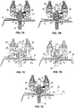
- the displaceable member 13 is adapted to move between a first end position P 1 , as shown in FIG. 6A , in which it is designed to interact with the movable tool 6 when the latter is vertically translated and a second end position P 2 , as shown in FIG. 6B , in which it cannot interact with movable tool 6.
- the displaceable member 13 is translated from the first end position P 1 to the second end position P 2 and vice versa by second actuator means 14 which act upon the displaceable member 13 to selectively change the configuration of the stationary tool 5 and form adjacent creases C with opposite orientations, without having to turn the article A upside down.
- the stationary member 12 is stably held in the first end position P 1 to interact with the movable tool 6 each time the latter is lifted to contact the respective face F I of the article A to form the crease C.
- the movable tool 6 consisting of a single elongate plate, has a median recess 10 and a pair of lateral punches 8, 8', facing the median punch 7 and the lateral recesses 9, 9' of the stationary tool 5, respectively.
- These guide means 19 are not connected to the control means and ensure repeatable, consistent positioning of the displaceable member 13, without requiring intensive maintenance.
- the slot comprises a first horizontal portion 22 and a second portion 23 substantially sloped inclined downwards relative to the horizontal.
- the first 22 and second 23 portions define respective sections of the curvilinear path T of the guide means 19 and form an angle ⁇ ranging from 160° to 170° at their junction.
- each displaceable member 13, 13' may comprise at least one respective slot 20, 20' formed on the side wall 24, 24' opposite to the one that contacts the stationary member 12.
- each pin 21, 21' fits in respective holes 30, 30' formed at the transverse ends 25, 26 of the stationary member 12 and has a smooth ground central portion 31 that is slidingly inserted in the slotted holes 20, 20'; 29, 29' and a head 32 at one longitudinal end for engagement of a wrench tool.
- a threaded portion 33 is provided at the opposite longitudinal end of the pin 21 for tightening a locknut 34, at least one elastic element, e.g. a disk spring 35, being interposed between the locknut 34 and the displaceable member 13'.
- a locknut 34 at least one elastic element, e.g. a disk spring 35, being interposed between the locknut 34 and the displaceable member 13'.
- the device 1 may comprise eccentric guide means 19 with a predetermined eccentricity, defining a substantially arc-shaped curvilinear path T.
- creases C are formed by first placing the cover A on the support surface 3 and feeding it toward the pair of tools 5, 6.
- the cover A is fed on the support surface 3 and the stationary tool 5 is configured with the displaceable members 13, 13' alternately placed in the first end position P 1 proximal to the cover A, with the pins 21, 21' alternately placed in the horizontal portion 22 of their respective slots 20, 29.
- Each interaction of the movable tool 6 with the stationary tool 5, in this configuration, will cause the formation of a pair of creases C, i.e. a downwardly directed crease and an upwardly directed crease, which correspond to a spine crease C D and a hinge crease respectively C C .
- both displaceable members 13, 13' will afford the formation of a pair of creases, a spine crease C D and a hinge crease C C .
- the invention relates to a machine, not shown, for creasing sheet-like covers A, which comprises the above discussed creasing device 1.
- the machine M further comprises a loading station for loading the articles A to be creased, a discharge station for discharging the creased articles A and means for transferring a cover at a time from the loading station to the support plate.
- the machine M may be of stand-alone type, i.e. adapted to operate alone or be mounted to a known sheet-binding apparatus.
- the present invention may find application in industry, because it can be produced on an industrial scale in the publishing and bookbinding industries.
Landscapes
- Engineering & Computer Science (AREA)
- Mechanical Engineering (AREA)
- Manufacturing & Machinery (AREA)
- Folding Of Thin Sheet-Like Materials, Special Discharging Devices, And Others (AREA)
- Machines For Manufacturing Corrugated Board In Mechanical Paper-Making Processes (AREA)
Claims (10)
- Un dispositif de rainage (1) pour former des rainures (C) dans du papier et des articles de reliure (A), ledit dispositif comprenant:un châssis (2) avec une surface de support sensiblement horizontale (3) pour supporter un article (A) à onduler et pour introduire l'article selon une direction sensiblement longitudinale (L);une paire d'outils opposés, un outil fixe (5) et un outil mobile (6), placés sur des côtés opposés de ladite surface de support (3), l'outil fixe (5) comprenant un élément fixe (12) faisant partie intégrante dudit cadre (2) et au moins un élément déplaçable (13) dont la position peut être ajustée en hauteur par rapport audit élément fixe (12);au moins un poinçon allongé (7, 8) et au moins un évidement allongé (9, 10), associés audit outil mobile (6) et audit outil fixe (5), dans des positions décalées longitudinalement;premiers moyens d'actionnement (11) agissant sur ledit outil mobile (6) pour le déplacer vers ledit outil fixe (5) et interagir avec les faces opposées (Fs, FI) de l'article (A), pour former une rainure (C);seconds moyens d'actionnement (14) agissant sur ledit élément mobile (13) pour le déplacer de manière sélective entre une première position finale (P1) dans laquelle il est conçu pour interagir avec ledit outil mobile (6), et une seconde position finale (P2) dans laquelle il ne peut pas interagir avec ledit outil mobile (6);des moyens de guidage (19) associés audit outil fixe (5) pour guider ledit au moins un élément déplaçable (13) entre ladite première position finale (P1) et ladite deuxième position finale (P2);caractérisé en ce que lesdits moyens de guidage (19) sont du type ayant un chemin curviligne (T) contenu dans un plan (π) sensiblement perpendiculaire à ladite surface de support (3) et à ladite direction longitudinale (L), lesdits moyens de guidage (19) comprenant une came constituée d'au moins une fente (20) formée sur l'un desdits éléments (12, 13) et d'au moins une broche (21) associée à l'autre desdits éléments (13, 12) pour une insertion glissante dans une fente correspondante (20), ladite fente (20) comprenant une première partie sensiblement horizontale (22) et une seconde partie sensiblement inclinée vers le bas (23) et inclinée par rapport à l'horizontale, les parties définissant respectivement les sections dudit chemin curviligne (T).
- Un dispositif selon la revendication 1, caractérisé en ce que ladite broche (21) est guidée de manière glissante par ladite partie horizontale (22) de ladite au moins une fente (20) lorsque ledit au moins un élément déplaçable (13) est dans ladite première position finale (P1), et par ladite partie inclinée (23) lorsque ledit élément déplaçable (13) est dans ladite seconde position finale (P2), ladite broche (21) pouvant être déplacée sans à-coups de ladite première partie (22) à ladite seconde partie (23) et inversement.
- Un dispositif selon la revendication 1, caractérisé en ce que ledit élément fixe (12) et ledit au moins un élément déplaçable (13) sont des plaques sensiblement rectangulaires allongées en vertical en contact glissant l'une par rapport à l'autre, ladite au moins une fente (20) étant formée sur ledit au moins un élément déplaçable (13) et ladite au moins une broche (21) étant associée audit élément fixe (12).
- Un dispositif selon la revendication 3, caractérisé en ce que ledit outil fixe (5) comprend un élément central fixe (12) et une paire d'éléments latéraux déplaçables (13, 13'), ledit élément central fixe (12) ayant un poinçon médian (7), lesdits éléments latéraux déplaçables (13, 13') présentant chacun un évidement latéral (9, 9') à la même distance dudit poinçon médian (7), ledit outil mobile (6) ayant un évidement médian (10) et une paire de poinçons latéraux (8, 8') faisant face respectivement au poinçon médian (7) et aux évidements latéraux (9, 9') dudit outil fixe (5).
- Un dispositif selon la revendication 4, caractérisé en ce que ledit élément central fixe (12) présente à ses extrémités transversales opposées (25, 26) des broches de guidage respectives (21, 21'), qui sont insérées de manière glissante dans des fentes correspondants (20, 29) formés aux extrémités transversales opposées (27, 28) de chacun desdits éléments latéraux déplaçables (13, 13').
- Un dispositif selon la revendication 4, caractérisé en ce que ledit élément fixe (12) a des trous respectifs (30, 30') au niveau de ses extrémités transversales (25, 26), pour recevoir lesdites broches de guidage (21, 21 '), ces dernières ayant une partie centrale lisse et moulue
insérée de manière glissante dans des trous oblongs respectifs (20, 29). - Un dispositif selon la revendication 5, caractérisé en ce que lesdites broches de guidage (21, 21') ont à une extrémité longitudinale une tête (32) destinée à recevoir une clé, et à l'extrémité opposée une partie filetée (33) pour visser un contre-écrou (34), au moins un élément élastique du type ressort à disque (35) étant interposé entre ledit contre-écrou (34) et ledit élément déplaçable (13).
- Un dispositif selon la revendication 1, caractérisé en ce que lesdits seconds moyens d'actionnement (14) comprennent un actionneur linéaire (15) avec une extrémité (16) articulée audit châssis (2) et une extrémité (17) articulée à chacun des éléments déplaçables (13), pour que ces dernières glissent par rapport audit élément fixe (12) le long desdits moyens de guidage (19).
- Un dispositif selon la revendication 1, caractérisé en ce que lesdits moyens de guidage (19) sont du type excentrique avec une excentricité prédéterminée et définissent ledit chemin curviligne sensiblement en forme d'arc (T).
- Machine à rainer pour former des rainures (C) dans du papier et des articles de reliure (A), comprenant un poste de chargement pour charger les articles à rainer, un poste de déchargement pour décharger les articles rainés, des moyens pour transférer les articles du poste de chargement au poste de déchargement, caractérisée en ce qu'elle comprend un dispositif de rainage (1) selon une ou plusieurs des revendications précédentes entre ledit poste de chargement et ledit poste de déchargement.
Applications Claiming Priority (2)
| Application Number | Priority Date | Filing Date | Title |
|---|---|---|---|
| ITUB2016A001084A ITUB20161084A1 (it) | 2016-02-26 | 2016-02-26 | Dispositivo di cordonatura per la realizzazione di cordoni di piegatura in articoli cartotecnici e di legatoria, nonche' macchina comprendente tale dispositivo |
| PCT/IB2017/051033 WO2017145082A1 (fr) | 2016-02-26 | 2017-02-23 | Dispositif de plissage destiné à la formation de plis dans du papier et à la reliure d'articles, et machine comprenant un tel dispositif |
Publications (2)
| Publication Number | Publication Date |
|---|---|
| EP3419833A1 EP3419833A1 (fr) | 2019-01-02 |
| EP3419833B1 true EP3419833B1 (fr) | 2019-08-28 |
Family
ID=56134471
Family Applications (1)
| Application Number | Title | Priority Date | Filing Date |
|---|---|---|---|
| EP17717223.6A Active EP3419833B1 (fr) | 2016-02-26 | 2017-02-23 | Dispositif de plissage destiné à la formation de plis dans du papier et à la reliure d'articles, et machine comprenant un tel dispositif |
Country Status (4)
| Country | Link |
|---|---|
| US (1) | US10919333B2 (fr) |
| EP (1) | EP3419833B1 (fr) |
| IT (1) | ITUB20161084A1 (fr) |
| WO (1) | WO2017145082A1 (fr) |
Families Citing this family (1)
| Publication number | Priority date | Publication date | Assignee | Title |
|---|---|---|---|---|
| CN113352700B (zh) * | 2021-07-06 | 2024-07-23 | 德日升纸制品包装河北有限公司 | 纸板导料压痕装置 |
Family Cites Families (27)
| Publication number | Priority date | Publication date | Assignee | Title |
|---|---|---|---|---|
| US3847036A (en) * | 1973-10-10 | 1974-11-12 | Centenary Central | Method of producing cutting plates for die cutting operations |
| US5709376A (en) * | 1995-01-30 | 1998-01-20 | Ricoh Company, Ltd. | Sheet finisher |
| US5797596A (en) * | 1995-04-27 | 1998-08-25 | Minolta Co., Ltd. | Finisher with a stapling function |
| NO311560B1 (no) * | 1996-02-16 | 2001-12-10 | Marbach Gmbh Karl | Fremgangsmåte til fremstilling av rillede, stansede deler fra en materialplate |
| US6364590B1 (en) * | 2000-08-01 | 2002-04-02 | Hewlett-Packard Company | Book cover preparation system |
| DE20021343U1 (de) * | 2000-12-16 | 2001-03-22 | E. Bickel GmbH, 74078 Heilbronn | Prägevorrichtung für Flachgut |
| US20060229184A1 (en) * | 2005-04-07 | 2006-10-12 | Hewlett-Packard Development Company, L.P. | Creaser |
| US7303519B2 (en) * | 2005-09-08 | 2007-12-04 | Palletkraft North America Corp. | Automatic machine and method for forming a corrugated pallet |
| BE1016747A3 (nl) * | 2005-09-27 | 2007-05-08 | Rillivo Bv Met Beperkte Aanspr | Verbeterde stansrilplaat. |
| US7770876B2 (en) * | 2007-08-28 | 2010-08-10 | Kabushiki Kaisha Toshiba | Creasing device, post-processing apparatus equipped therewith, creasing method, image forming apparatus and crease-added printing method |
| JP4869215B2 (ja) * | 2007-12-13 | 2012-02-08 | 株式会社リコー | シート折り装置、シート搬送装置、シート処理装置、及び画像形成装置 |
| JP4506836B2 (ja) * | 2008-01-14 | 2010-07-21 | 富士ゼロックス株式会社 | 折り筋装置及びこれを用いた後処理装置並びに記録材処理装置 |
| DE102008049617A1 (de) * | 2008-09-30 | 2010-04-08 | Pernuma Gmbh | Vorrichtung zum Einbringen von Nuten in einen Karton- oder Papierbogen, Verfahren hierzu sowie Verwendung einer derartigen Vorrichtung |
| DE102008060073A1 (de) * | 2008-12-02 | 2010-06-10 | Dgr-Graphic Gmbh | Rillung von Umschlägen in einem Klebebinder |
| JP5332694B2 (ja) * | 2009-02-16 | 2013-11-06 | 株式会社リコー | シート処理システム、シート供給制御方法、及びシート供給制御プログラム |
| JP2011093708A (ja) * | 2009-09-30 | 2011-05-12 | Ricoh Co Ltd | 画像形成装置 |
| JP2011111302A (ja) * | 2009-11-27 | 2011-06-09 | Ricoh Co Ltd | 折り跡付け装置、及び画像形成システム |
| CN102741058B (zh) * | 2010-02-02 | 2014-10-29 | 好利用国际株式会社 | 对于向主体粘贴前的封面加入折弯加工用的纹线的装置 |
| JP2011251816A (ja) * | 2010-06-02 | 2011-12-15 | Ricoh Co Ltd | 筋付け装置、及び画像形成システム |
| JP2011256002A (ja) * | 2010-06-08 | 2011-12-22 | Ricoh Co Ltd | 筋付け装置、及び画像形成システム |
| JP5605149B2 (ja) * | 2010-10-12 | 2014-10-15 | 株式会社リコー | 筋付け装置及び画像形成システム |
| JP5671953B2 (ja) * | 2010-11-08 | 2015-02-18 | 株式会社リコー | 筋付け装置及び画像形成システム |
| JP5625870B2 (ja) * | 2010-12-16 | 2014-11-19 | 株式会社リコー | 筋付け装置及び画像形成システム |
| EP2845829B1 (fr) * | 2012-05-01 | 2017-06-28 | Horizon International Inc. | Dispositif de rainurage et de pliage |
| US8831503B2 (en) * | 2012-06-05 | 2014-09-09 | Xerox Corporation | Creasing apparatus having rotating base with recess |
| JP5995564B2 (ja) * | 2012-07-11 | 2016-09-21 | キヤノン株式会社 | シート処理装置及び画像形成装置 |
| JP2016030671A (ja) * | 2014-07-29 | 2016-03-07 | キヤノン株式会社 | シート処理装置及びその制御方法、並びにプログラム |
-
2016
- 2016-02-26 IT ITUB2016A001084A patent/ITUB20161084A1/it unknown
-
2017
- 2017-02-23 WO PCT/IB2017/051033 patent/WO2017145082A1/fr not_active Ceased
- 2017-02-23 US US16/079,007 patent/US10919333B2/en not_active Expired - Fee Related
- 2017-02-23 EP EP17717223.6A patent/EP3419833B1/fr active Active
Non-Patent Citations (1)
| Title |
|---|
| None * |
Also Published As
| Publication number | Publication date |
|---|---|
| WO2017145082A1 (fr) | 2017-08-31 |
| US10919333B2 (en) | 2021-02-16 |
| ITUB20161084A1 (it) | 2017-08-26 |
| EP3419833A1 (fr) | 2019-01-02 |
| US20190047313A1 (en) | 2019-02-14 |
Similar Documents
| Publication | Publication Date | Title |
|---|---|---|
| US20040167002A1 (en) | Rail assembly for blanking tool insert | |
| AU710135B2 (en) | Means for a machine for cutting sheet elements, and associated arrangements | |
| US20150148210A1 (en) | Assembly for custom box blank preparation and method | |
| CN102285149B (zh) | 页张模切机的模切和/或压印站 | |
| US4410170A (en) | Machine for stapling and folding a stack of paper sheets to form a book | |
| EP3419833B1 (fr) | Dispositif de plissage destiné à la formation de plis dans du papier et à la reliure d'articles, et machine comprenant un tel dispositif | |
| KR101772752B1 (ko) | 부스바용 펀칭장치 | |
| KR100426598B1 (ko) | 복사기의 용지처리장치 | |
| EP3012053B1 (fr) | Machine pour découper des panneaux en bois, en plastique ou similaire | |
| JP7178317B2 (ja) | 寸法可変の蓋製造方法および寸法可変の蓋製造装置 | |
| NL8002766A (nl) | Ponsmachine. | |
| JP6790106B2 (ja) | インサートシートを把持するためのデバイス、装填デバイス、ブランクを受け入れるためのステーション、及びシートの形態の要素を加工するための機械 | |
| TW480215B (en) | A device for positioning sheets in a machine station | |
| JP7815260B2 (ja) | シート材料加工工具、シート材料加工ステーション及びシート材料加工機 | |
| NL9200570A (nl) | Werkwijze en inrichting voor het nieten van stapels vellen. | |
| CN116648337B (zh) | 工具夹持组件和组件 | |
| KR100997072B1 (ko) | 스테이플러 | |
| US10850414B2 (en) | Sheet material processing device and sheet material processing apparatus | |
| CN106625843A (zh) | 纸板开槽机 | |
| JP2786427B2 (ja) | 切断工具用迅速ロックチェース | |
| NL1030437C2 (nl) | Inrichting voor het registreren van vellen. | |
| KR20150005635A (ko) | 프레임을 구비한 모듈 및 이 모듈이 제공된 폴더/글루어 | |
| CN209478339U (zh) | 一种全自动模切机压纸装置 | |
| CN112313164B (zh) | 储存装置及片材状元件成型机 | |
| JP2010052105A (ja) | 半自動平盤打抜機 |
Legal Events
| Date | Code | Title | Description |
|---|---|---|---|
| STAA | Information on the status of an ep patent application or granted ep patent |
Free format text: STATUS: UNKNOWN |
|
| STAA | Information on the status of an ep patent application or granted ep patent |
Free format text: STATUS: THE INTERNATIONAL PUBLICATION HAS BEEN MADE |
|
| PUAI | Public reference made under article 153(3) epc to a published international application that has entered the european phase |
Free format text: ORIGINAL CODE: 0009012 |
|
| STAA | Information on the status of an ep patent application or granted ep patent |
Free format text: STATUS: REQUEST FOR EXAMINATION WAS MADE |
|
| 17P | Request for examination filed |
Effective date: 20180830 |
|
| AK | Designated contracting states |
Kind code of ref document: A1 Designated state(s): AL AT BE BG CH CY CZ DE DK EE ES FI FR GB GR HR HU IE IS IT LI LT LU LV MC MK MT NL NO PL PT RO RS SE SI SK SM TR |
|
| AX | Request for extension of the european patent |
Extension state: BA ME |
|
| GRAP | Despatch of communication of intention to grant a patent |
Free format text: ORIGINAL CODE: EPIDOSNIGR1 |
|
| STAA | Information on the status of an ep patent application or granted ep patent |
Free format text: STATUS: GRANT OF PATENT IS INTENDED |
|
| INTG | Intention to grant announced |
Effective date: 20190424 |
|
| DAV | Request for validation of the european patent (deleted) | ||
| DAX | Request for extension of the european patent (deleted) | ||
| GRAS | Grant fee paid |
Free format text: ORIGINAL CODE: EPIDOSNIGR3 |
|
| GRAA | (expected) grant |
Free format text: ORIGINAL CODE: 0009210 |
|
| STAA | Information on the status of an ep patent application or granted ep patent |
Free format text: STATUS: THE PATENT HAS BEEN GRANTED |
|
| AK | Designated contracting states |
Kind code of ref document: B1 Designated state(s): AL AT BE BG CH CY CZ DE DK EE ES FI FR GB GR HR HU IE IS IT LI LT LU LV MC MK MT NL NO PL PT RO RS SE SI SK SM TR |
|
| REG | Reference to a national code |
Ref country code: GB Ref legal event code: FG4D |
|
| REG | Reference to a national code |
Ref country code: CH Ref legal event code: EP |
|
| REG | Reference to a national code |
Ref country code: AT Ref legal event code: REF Ref document number: 1171933 Country of ref document: AT Kind code of ref document: T Effective date: 20190915 |
|
| REG | Reference to a national code |
Ref country code: IE Ref legal event code: FG4D |
|
| REG | Reference to a national code |
Ref country code: DE Ref legal event code: R096 Ref document number: 602017006584 Country of ref document: DE |
|
| REG | Reference to a national code |
Ref country code: SE Ref legal event code: TRGR |
|
| REG | Reference to a national code |
Ref country code: NL Ref legal event code: MP Effective date: 20190828 |
|
| REG | Reference to a national code |
Ref country code: LT Ref legal event code: MG4D |
|
| PG25 | Lapsed in a contracting state [announced via postgrant information from national office to epo] |
Ref country code: FI Free format text: LAPSE BECAUSE OF FAILURE TO SUBMIT A TRANSLATION OF THE DESCRIPTION OR TO PAY THE FEE WITHIN THE PRESCRIBED TIME-LIMIT Effective date: 20190828 Ref country code: NO Free format text: LAPSE BECAUSE OF FAILURE TO SUBMIT A TRANSLATION OF THE DESCRIPTION OR TO PAY THE FEE WITHIN THE PRESCRIBED TIME-LIMIT Effective date: 20191128 Ref country code: PT Free format text: LAPSE BECAUSE OF FAILURE TO SUBMIT A TRANSLATION OF THE DESCRIPTION OR TO PAY THE FEE WITHIN THE PRESCRIBED TIME-LIMIT Effective date: 20191230 Ref country code: BG Free format text: LAPSE BECAUSE OF FAILURE TO SUBMIT A TRANSLATION OF THE DESCRIPTION OR TO PAY THE FEE WITHIN THE PRESCRIBED TIME-LIMIT Effective date: 20191128 Ref country code: NL Free format text: LAPSE BECAUSE OF FAILURE TO SUBMIT A TRANSLATION OF THE DESCRIPTION OR TO PAY THE FEE WITHIN THE PRESCRIBED TIME-LIMIT Effective date: 20190828 Ref country code: HR Free format text: LAPSE BECAUSE OF FAILURE TO SUBMIT A TRANSLATION OF THE DESCRIPTION OR TO PAY THE FEE WITHIN THE PRESCRIBED TIME-LIMIT Effective date: 20190828 Ref country code: LT Free format text: LAPSE BECAUSE OF FAILURE TO SUBMIT A TRANSLATION OF THE DESCRIPTION OR TO PAY THE FEE WITHIN THE PRESCRIBED TIME-LIMIT Effective date: 20190828 |
|
| PG25 | Lapsed in a contracting state [announced via postgrant information from national office to epo] |
Ref country code: AL Free format text: LAPSE BECAUSE OF FAILURE TO SUBMIT A TRANSLATION OF THE DESCRIPTION OR TO PAY THE FEE WITHIN THE PRESCRIBED TIME-LIMIT Effective date: 20190828 Ref country code: LV Free format text: LAPSE BECAUSE OF FAILURE TO SUBMIT A TRANSLATION OF THE DESCRIPTION OR TO PAY THE FEE WITHIN THE PRESCRIBED TIME-LIMIT Effective date: 20190828 Ref country code: GR Free format text: LAPSE BECAUSE OF FAILURE TO SUBMIT A TRANSLATION OF THE DESCRIPTION OR TO PAY THE FEE WITHIN THE PRESCRIBED TIME-LIMIT Effective date: 20191129 Ref country code: ES Free format text: LAPSE BECAUSE OF FAILURE TO SUBMIT A TRANSLATION OF THE DESCRIPTION OR TO PAY THE FEE WITHIN THE PRESCRIBED TIME-LIMIT Effective date: 20190828 Ref country code: IS Free format text: LAPSE BECAUSE OF FAILURE TO SUBMIT A TRANSLATION OF THE DESCRIPTION OR TO PAY THE FEE WITHIN THE PRESCRIBED TIME-LIMIT Effective date: 20191228 Ref country code: RS Free format text: LAPSE BECAUSE OF FAILURE TO SUBMIT A TRANSLATION OF THE DESCRIPTION OR TO PAY THE FEE WITHIN THE PRESCRIBED TIME-LIMIT Effective date: 20190828 |
|
| REG | Reference to a national code |
Ref country code: AT Ref legal event code: MK05 Ref document number: 1171933 Country of ref document: AT Kind code of ref document: T Effective date: 20190828 |
|
| PG25 | Lapsed in a contracting state [announced via postgrant information from national office to epo] |
Ref country code: TR Free format text: LAPSE BECAUSE OF FAILURE TO SUBMIT A TRANSLATION OF THE DESCRIPTION OR TO PAY THE FEE WITHIN THE PRESCRIBED TIME-LIMIT Effective date: 20190828 |
|
| PG25 | Lapsed in a contracting state [announced via postgrant information from national office to epo] |
Ref country code: RO Free format text: LAPSE BECAUSE OF FAILURE TO SUBMIT A TRANSLATION OF THE DESCRIPTION OR TO PAY THE FEE WITHIN THE PRESCRIBED TIME-LIMIT Effective date: 20190828 Ref country code: PL Free format text: LAPSE BECAUSE OF FAILURE TO SUBMIT A TRANSLATION OF THE DESCRIPTION OR TO PAY THE FEE WITHIN THE PRESCRIBED TIME-LIMIT Effective date: 20190828 Ref country code: DK Free format text: LAPSE BECAUSE OF FAILURE TO SUBMIT A TRANSLATION OF THE DESCRIPTION OR TO PAY THE FEE WITHIN THE PRESCRIBED TIME-LIMIT Effective date: 20190828 Ref country code: EE Free format text: LAPSE BECAUSE OF FAILURE TO SUBMIT A TRANSLATION OF THE DESCRIPTION OR TO PAY THE FEE WITHIN THE PRESCRIBED TIME-LIMIT Effective date: 20190828 Ref country code: AT Free format text: LAPSE BECAUSE OF FAILURE TO SUBMIT A TRANSLATION OF THE DESCRIPTION OR TO PAY THE FEE WITHIN THE PRESCRIBED TIME-LIMIT Effective date: 20190828 |
|
| PG25 | Lapsed in a contracting state [announced via postgrant information from national office to epo] |
Ref country code: CZ Free format text: LAPSE BECAUSE OF FAILURE TO SUBMIT A TRANSLATION OF THE DESCRIPTION OR TO PAY THE FEE WITHIN THE PRESCRIBED TIME-LIMIT Effective date: 20190828 Ref country code: SM Free format text: LAPSE BECAUSE OF FAILURE TO SUBMIT A TRANSLATION OF THE DESCRIPTION OR TO PAY THE FEE WITHIN THE PRESCRIBED TIME-LIMIT Effective date: 20190828 Ref country code: IS Free format text: LAPSE BECAUSE OF FAILURE TO SUBMIT A TRANSLATION OF THE DESCRIPTION OR TO PAY THE FEE WITHIN THE PRESCRIBED TIME-LIMIT Effective date: 20200224 Ref country code: SK Free format text: LAPSE BECAUSE OF FAILURE TO SUBMIT A TRANSLATION OF THE DESCRIPTION OR TO PAY THE FEE WITHIN THE PRESCRIBED TIME-LIMIT Effective date: 20190828 |
|
| REG | Reference to a national code |
Ref country code: DE Ref legal event code: R097 Ref document number: 602017006584 Country of ref document: DE |
|
| PLBE | No opposition filed within time limit |
Free format text: ORIGINAL CODE: 0009261 |
|
| STAA | Information on the status of an ep patent application or granted ep patent |
Free format text: STATUS: NO OPPOSITION FILED WITHIN TIME LIMIT |
|
| PG2D | Information on lapse in contracting state deleted |
Ref country code: IS |
|
| 26N | No opposition filed |
Effective date: 20200603 |
|
| REG | Reference to a national code |
Ref country code: BE Ref legal event code: MM Effective date: 20200229 |
|
| PG25 | Lapsed in a contracting state [announced via postgrant information from national office to epo] |
Ref country code: MC Free format text: LAPSE BECAUSE OF FAILURE TO SUBMIT A TRANSLATION OF THE DESCRIPTION OR TO PAY THE FEE WITHIN THE PRESCRIBED TIME-LIMIT Effective date: 20190828 Ref country code: LU Free format text: LAPSE BECAUSE OF NON-PAYMENT OF DUE FEES Effective date: 20200223 |
|
| PG25 | Lapsed in a contracting state [announced via postgrant information from national office to epo] |
Ref country code: BE Free format text: LAPSE BECAUSE OF NON-PAYMENT OF DUE FEES Effective date: 20200229 |
|
| PGFP | Annual fee paid to national office [announced via postgrant information from national office to epo] |
Ref country code: IE Payment date: 20220216 Year of fee payment: 6 Ref country code: CH Payment date: 20220218 Year of fee payment: 6 |
|
| PG25 | Lapsed in a contracting state [announced via postgrant information from national office to epo] |
Ref country code: MT Free format text: LAPSE BECAUSE OF FAILURE TO SUBMIT A TRANSLATION OF THE DESCRIPTION OR TO PAY THE FEE WITHIN THE PRESCRIBED TIME-LIMIT Effective date: 20190828 Ref country code: CY Free format text: LAPSE BECAUSE OF FAILURE TO SUBMIT A TRANSLATION OF THE DESCRIPTION OR TO PAY THE FEE WITHIN THE PRESCRIBED TIME-LIMIT Effective date: 20190828 |
|
| PGFP | Annual fee paid to national office [announced via postgrant information from national office to epo] |
Ref country code: SE Payment date: 20220218 Year of fee payment: 6 |
|
| PG25 | Lapsed in a contracting state [announced via postgrant information from national office to epo] |
Ref country code: MK Free format text: LAPSE BECAUSE OF FAILURE TO SUBMIT A TRANSLATION OF THE DESCRIPTION OR TO PAY THE FEE WITHIN THE PRESCRIBED TIME-LIMIT Effective date: 20190828 |
|
| P01 | Opt-out of the competence of the unified patent court (upc) registered |
Effective date: 20230606 |
|
| PG25 | Lapsed in a contracting state [announced via postgrant information from national office to epo] |
Ref country code: SI Free format text: LAPSE BECAUSE OF FAILURE TO SUBMIT A TRANSLATION OF THE DESCRIPTION OR TO PAY THE FEE WITHIN THE PRESCRIBED TIME-LIMIT Effective date: 20190828 |
|
| REG | Reference to a national code |
Ref country code: CH Ref legal event code: PL |
|
| REG | Reference to a national code |
Ref country code: SE Ref legal event code: EUG |
|
| PG25 | Lapsed in a contracting state [announced via postgrant information from national office to epo] |
Ref country code: SE Free format text: LAPSE BECAUSE OF NON-PAYMENT OF DUE FEES Effective date: 20230224 Ref country code: LI Free format text: LAPSE BECAUSE OF NON-PAYMENT OF DUE FEES Effective date: 20230228 Ref country code: CH Free format text: LAPSE BECAUSE OF NON-PAYMENT OF DUE FEES Effective date: 20230228 |
|
| REG | Reference to a national code |
Ref country code: IE Ref legal event code: MM4A |
|
| PG25 | Lapsed in a contracting state [announced via postgrant information from national office to epo] |
Ref country code: IE Free format text: LAPSE BECAUSE OF NON-PAYMENT OF DUE FEES Effective date: 20230223 |
|
| PGFP | Annual fee paid to national office [announced via postgrant information from national office to epo] |
Ref country code: GB Payment date: 20260223 Year of fee payment: 10 |
|
| PGFP | Annual fee paid to national office [announced via postgrant information from national office to epo] |
Ref country code: DE Payment date: 20260220 Year of fee payment: 10 |
|
| PGFP | Annual fee paid to national office [announced via postgrant information from national office to epo] |
Ref country code: IT Payment date: 20260220 Year of fee payment: 10 |
|
| PGFP | Annual fee paid to national office [announced via postgrant information from national office to epo] |
Ref country code: FR Payment date: 20260224 Year of fee payment: 10 |