EP3420183B1 - Appareil et procédé de revêtement de paroi interne de conduit - Google Patents
Appareil et procédé de revêtement de paroi interne de conduit Download PDFInfo
- Publication number
- EP3420183B1 EP3420183B1 EP17714031.6A EP17714031A EP3420183B1 EP 3420183 B1 EP3420183 B1 EP 3420183B1 EP 17714031 A EP17714031 A EP 17714031A EP 3420183 B1 EP3420183 B1 EP 3420183B1
- Authority
- EP
- European Patent Office
- Prior art keywords
- piece
- conduit
- adhesive
- sheet
- wall
- Prior art date
- Legal status (The legal status is an assumption and is not a legal conclusion. Google has not performed a legal analysis and makes no representation as to the accuracy of the status listed.)
- Active
Links
Images


Classifications
-
- F—MECHANICAL ENGINEERING; LIGHTING; HEATING; WEAPONS; BLASTING
- F16—ENGINEERING ELEMENTS AND UNITS; GENERAL MEASURES FOR PRODUCING AND MAINTAINING EFFECTIVE FUNCTIONING OF MACHINES OR INSTALLATIONS; THERMAL INSULATION IN GENERAL
- F16L—PIPES; JOINTS OR FITTINGS FOR PIPES; SUPPORTS FOR PIPES, CABLES OR PROTECTIVE TUBING; MEANS FOR THERMAL INSULATION IN GENERAL
- F16L55/00—Devices or appurtenances for use in, or in connection with, pipes or pipe systems
- F16L55/16—Devices for covering leaks in pipes or hoses, e.g. hose-menders
- F16L55/162—Devices for covering leaks in pipes or hoses, e.g. hose-menders from inside the pipe
- F16L55/165—Devices for covering leaks in pipes or hoses, e.g. hose-menders from inside the pipe a pipe or flexible liner being inserted in the damaged section
- F16L55/1652—Devices for covering leaks in pipes or hoses, e.g. hose-menders from inside the pipe a pipe or flexible liner being inserted in the damaged section the flexible liner being pulled into the damaged section
- F16L55/1653—Devices for covering leaks in pipes or hoses, e.g. hose-menders from inside the pipe a pipe or flexible liner being inserted in the damaged section the flexible liner being pulled into the damaged section and being pressed into contact with the pipe by a tool which moves inside along the pipe
-
- E—FIXED CONSTRUCTIONS
- E21—EARTH OR ROCK DRILLING; MINING
- E21B—EARTH OR ROCK DRILLING; OBTAINING OIL, GAS, WATER, SOLUBLE OR MELTABLE MATERIALS OR A SLURRY OF MINERALS FROM WELLS
- E21B17/00—Drilling rods or pipes; Flexible drill strings; Kellies; Drill collars; Sucker rods; Cables; Casings; Tubings
-
- E—FIXED CONSTRUCTIONS
- E21—EARTH OR ROCK DRILLING; MINING
- E21B—EARTH OR ROCK DRILLING; OBTAINING OIL, GAS, WATER, SOLUBLE OR MELTABLE MATERIALS OR A SLURRY OF MINERALS FROM WELLS
- E21B43/00—Methods or apparatus for obtaining oil, gas, water, soluble or meltable materials or a slurry of minerals from wells
- E21B43/02—Subsoil filtering
- E21B43/10—Setting of casings, screens, liners or the like in wells
- E21B43/103—Setting of casings, screens, liners or the like in wells of expandable casings, screens, liners, or the like
- E21B43/108—Expandable screens or perforated liners
-
- F—MECHANICAL ENGINEERING; LIGHTING; HEATING; WEAPONS; BLASTING
- F16—ENGINEERING ELEMENTS AND UNITS; GENERAL MEASURES FOR PRODUCING AND MAINTAINING EFFECTIVE FUNCTIONING OF MACHINES OR INSTALLATIONS; THERMAL INSULATION IN GENERAL
- F16L—PIPES; JOINTS OR FITTINGS FOR PIPES; SUPPORTS FOR PIPES, CABLES OR PROTECTIVE TUBING; MEANS FOR THERMAL INSULATION IN GENERAL
- F16L1/00—Laying or reclaiming pipes; Repairing or joining pipes on or under water
-
- F—MECHANICAL ENGINEERING; LIGHTING; HEATING; WEAPONS; BLASTING
- F16—ENGINEERING ELEMENTS AND UNITS; GENERAL MEASURES FOR PRODUCING AND MAINTAINING EFFECTIVE FUNCTIONING OF MACHINES OR INSTALLATIONS; THERMAL INSULATION IN GENERAL
- F16L—PIPES; JOINTS OR FITTINGS FOR PIPES; SUPPORTS FOR PIPES, CABLES OR PROTECTIVE TUBING; MEANS FOR THERMAL INSULATION IN GENERAL
- F16L55/00—Devices or appurtenances for use in, or in connection with, pipes or pipe systems
- F16L55/16—Devices for covering leaks in pipes or hoses, e.g. hose-menders
- F16L55/162—Devices for covering leaks in pipes or hoses, e.g. hose-menders from inside the pipe
- F16L55/163—Devices for covering leaks in pipes or hoses, e.g. hose-menders from inside the pipe a ring, a band or a sleeve being pressed against the inner surface of the pipe
-
- F—MECHANICAL ENGINEERING; LIGHTING; HEATING; WEAPONS; BLASTING
- F16—ENGINEERING ELEMENTS AND UNITS; GENERAL MEASURES FOR PRODUCING AND MAINTAINING EFFECTIVE FUNCTIONING OF MACHINES OR INSTALLATIONS; THERMAL INSULATION IN GENERAL
- F16L—PIPES; JOINTS OR FITTINGS FOR PIPES; SUPPORTS FOR PIPES, CABLES OR PROTECTIVE TUBING; MEANS FOR THERMAL INSULATION IN GENERAL
- F16L55/00—Devices or appurtenances for use in, or in connection with, pipes or pipe systems
- F16L55/16—Devices for covering leaks in pipes or hoses, e.g. hose-menders
- F16L55/162—Devices for covering leaks in pipes or hoses, e.g. hose-menders from inside the pipe
- F16L55/165—Devices for covering leaks in pipes or hoses, e.g. hose-menders from inside the pipe a pipe or flexible liner being inserted in the damaged section
- F16L55/1656—Devices for covering leaks in pipes or hoses, e.g. hose-menders from inside the pipe a pipe or flexible liner being inserted in the damaged section materials for flexible liners
-
- F—MECHANICAL ENGINEERING; LIGHTING; HEATING; WEAPONS; BLASTING
- F16—ENGINEERING ELEMENTS AND UNITS; GENERAL MEASURES FOR PRODUCING AND MAINTAINING EFFECTIVE FUNCTIONING OF MACHINES OR INSTALLATIONS; THERMAL INSULATION IN GENERAL
- F16L—PIPES; JOINTS OR FITTINGS FOR PIPES; SUPPORTS FOR PIPES, CABLES OR PROTECTIVE TUBING; MEANS FOR THERMAL INSULATION IN GENERAL
- F16L55/00—Devices or appurtenances for use in, or in connection with, pipes or pipe systems
- F16L55/18—Appliances for use in repairing pipes
Definitions
- the present invention relates to conduits and, in particular, it relates to a method of lining at least one part of an internal wall of a wellbore conduit.
- equipment of various kinds may be emplaced (initially or during the life of the well) in the wellbore, such as sand screens, valves, sleeves, plugs, or the like.
- a sand screen or a sleeve may be installed for instance by running the screen or sleeve into the wellbore and setting packers at its respective ends. It may be desirable after a period of use, e.g. by way of a well intervention, to line part of the wall in the far reaches of the wellbore.
- the presence of previously installed equipment can reduce access to prevent such an operation from taking place, or may place constraints on the types of equipment, solutions, or processes that can be utilised in order to do so. It is an aim of the invention to obviate or mitigate difficulties or drawbacks associated with prior art techniques, and/or to improve upon prior art techniques in the above field.
- US 6138718 A Describes a method and apparatus wherein a gasket is provided with a curable sealant to repair a conduit.
- the gasket is pressurized against a wall of the conduit by a force exerted onto it from a sleeve, which in turn may be expanded by use of a pressurizing device.
- US 5186215 A discloses a method and apparatus for repair of a pipepline where an initially collapsed tube is surrounded by a circumferentially continuous gasket or sealant sleeve for sealing the pipeline.
- the tube is selectively expanded by a remotely controlled inflatable bladder or mandrel to thereby expand the circumference of the gasket sleeve and urge that sleeve against the interior wall of the pipe section to be repaired.
- the step of allowing the inserted piece of material to at least partially uncurl or unroll inside the conduit is typically performed to position the piece of material at the part of the internal wall of the conduit to be lined. By doing so, once positioned, a section of the piece of material overlaps at least one other section of the piece of material.
- the positioned piece of material may thus be arranged in layers adjacent to the wall of the conduit where the sections are in overlap.
- the laminate comprises a combination of the overlapping sections and an amount of the adhesive, or a combination of the layers and an amount of the adhesive.
- the laminate is typically a tubular laminate, e.g. if the piece of material is positioned at the part of the internal wall to be lined so as to encircle an inside circumference of the conduit, upon the piece of material at least partially uncurling or unrolling via step d.
- the laminate typically includes the adhesive and the layers formed by the overlapping sections of the piece of material.
- the piece of material When positioned at the part of the internal wall of the conduit to be lined, the piece of material is typically wound in a tubular roll wherein sections of the piece of material overlap such that the roll is provided with layers formed by the sections where the sections are in overlap.
- the method includes rolling or curling up the piece of material into a tubular roll.
- An overlapping region may be formed by the rolling or curling up the piece of material into a tubular roll.
- sections of the piece of material may overlap one another to obtain overlying layers in the roll where the sections are in overlap.
- step a the piece of material is rolled or curled up in a tubular roll having a first configuration, and in step c the tubular roll is inserted end-first into the conduit in the first configuration.
- step c the tubular roll is inserted end-first into the conduit in the first configuration.
- the step of allowing the inserted piece of material to at least partially uncurl or unroll inside the conduit is performed to position the piece of material at the part of the internal wall to be lined, such that when positioned the piece of material is configured in a tubular roll having a second configuration. In the second configuration, the tubular roll has a larger diameter than in the first configuration.
- step d the piece of material in the roll at least partially unrolls or uncurls inside the conduit thereby reducing an extent of the overlap between the sections in overlap.
- the roll thus expands diametrically to position the piece of material against the part of the internal wall to be lined.
- the piece of material is in overlap such that one section of the sheet overlaps with at least one other section of the sheet.
- the laminate obtained is a tubular laminate.
- an inner section of the piece of material When in overlap e.g. in the roll when positioned against the wall of the conduit, an inner section of the piece of material typically has a greater curvature, or a tighter arc, than an outer section (radially outwardly with respect to a central long axis of conduit).
- the inner section may thus be nested within the outer section.
- An amount of the adhesive may be disposed between an outer surface of the roll and the internal wall of the conduit.
- An amount of the adhesive may also be disposed between adjacent overlapping sections of the piece of material, e.g. between an outer surface of a first, inner section and an inner surface of a second, outer section of the piece of material.
- an amount of the adhesive may be disposed between any one or more pairs, or each pair of adjacent overlapping sections of the piece of material.
- the adhesive may thus combine with the sections of the piece of material to produce a laminate which can line the wall of the conduit and which may be secured onto the wall using the adhesive.
- the laminate can advantageously be very thin whilst providing good sealing opportunity over the part of the internal wall to which the material is applied.
- the laminate may typically be a solid structure, and be configured to withstand a pressure differential between an inside of the conduit and an outside of the conduit, e.g. during subsequent use of the lined conduit in conveying a fluid through the conduit.
- the piece of material has a thickness in the range of 0.10 to 0.40 mm.
- the laminate may typically have a thickness in the range of 0.20 to 3.00 mm.
- the adhesive may typically be provided on the piece of material, so as to be carried into the conduit on the piece of material in step c.
- the method further comprises preparing the piece of material in advance.
- the method comprises providing the piece of material with the adhesive prior to being curled or rolled up.
- the piece of material is rolled or curled up with the adhesive applied to the material.
- the method may further comprise spreading the adhesive across a surface of the piece of material.
- the method may include applying the adhesive to either or both sides of the piece of material to prepare the material in advance.
- step d the adhesive can be urged against the wall.
- the adhesive may be further utilised in step d to seal between the piece of material and said part of the internal wall of the conduit.
- the piece of material is configured to be flexible and resilient. Hence, the piece of material responds resiliently to flexure, e.g. as a spring. The material is urged toward and against the wall.
- the piece of material may be positioned at the wall of the conduit. Accordingly, the piece of material is applied against the wall by the structure expanding radially when it at least partially uncurls or unrolls.
- the piece of material may preferably comprise a sheet, typically a spring steel sheet. More generally, the sheet may be a plastics sheet or metal sheet.
- the piece of material is provided on an inserter tool in a first configuration.
- the method includes running the inserter tool to a desired location in the conduit; and releasing the piece of material from the inserter tool at the desired location.
- the inserter tool is configured to hold the piece of material in the first configuration while the inserter tool is inserted into the desired location in the conduit.
- the piece of material is then released so as to at least partially uncurl or unroll inside the conduit into a second configuration, in which the piece of material may be positioned at the part of the wall of the conduit to be lined.
- the method may further comprise moving the inserter tool out of the conduit, leaving the piece of material in place against the wall.
- the piece of material may typically expand radially within conduit upon at least partially uncurling or unrolling in step d.
- the method includes the steps of:
- the method may further comprise: using a heater which is provided as part of the inserter tool to heat the piece of material to post-cure the adhesive, so as to utilise the adhesive to secure the piece of material in place.
- the adhesive may be configured to sealingly secure the piece of material onto the wall of the conduit. In this way, a fluid tight seal between the piece of material and the internal wall of the conduit may be produced by the adhesive. Accordingly, the material may be applied to the wall to isolate an interior of the conduit from a region outside the wall.
- the piece of material may be provided with a sealer, wherein the sealer may seal between the piece of material and the internal wall of the conduit, upon the material being applied to the wall.
- the sealer may be configured for sealing between the resilient sheet and the wall of the conduit.
- the sealer may accordingly be seated between the resilient sheet and the wall to which the sheet is applied upon applying the sheet.
- the adhesive may together with the sealer provide for sealing and adhesion of the piece of material to the wall of the conduit, upon performing step d.
- the sealer may be a sealant.
- the sealer may comprise a body of rubber, e.g. an elastomer seal, or may comprise a swellable material.
- the swellable material may be adapted to swell in response to the environment in the conduit, e.g. in response to a particular fluid contained in the conduit, such as for instance any of oil, water, and/or gas.
- the swellable material may be adapted to swell in response to a property of the fluid in the conduit.
- the swellable material may be adapted to swell after exposure to the environment of the fluid for a certain period of time.
- the sealer may comprise a swelling agent for activating the swellable material to swell.
- the adhesive may be adapted to initiate swelling of the swellable material for sealing between the internal wall of the conduit and the piece of material.
- the method may include providing a structure on the piece of material for reinforcing the laminate.
- the method may include embedding at least some of the adhesive in a structure, e.g. a sponge or net structure provided on the piece of material, e.g. on a surface on either or both sides of the piece of material. This may help to reinforce the laminate.
- the material of such structures, e.g. the net may comprise carbon or another material.
- the adhesive may be embedded before rolling or curling up the piece of material.
- the conduit is a wellbore conduit.
- the conduit may comprise a section of casing or a section of a liner in a wellbore.
- the wellbore may be a wellbore of an oil and gas well.
- the conduit may comprise any type of pipe or tubing for carrying any type of fluid.
- a fluid may be in the form of liquid or gas, or a combination thereof.
- the fluid carried in the tubing may comprise a well fluid, such as for instance production fluid comprising hydrocarbons from the Earth's subsurface.
- the conduit may comprise a pipe or tubing for use in an oil and gas wellbore.
- the conduit, pipe and/or tubing may comprise one or more tubulars of metal (e.g. steel), composite, or plastics materials.
- the pipe or tubing may comprise steel, composite or plastics tubulars for use in an oil and gas well.
- the conduit may comprise a pipe or tubing for conveying water.
- the pipe or tubing may comprise steel or plastics tubulars used for conveying cold or hot water.
- the adhesive may typically comprise at least one of: epoxy; glue; thermoset adhesive; single-component adhesive; two-component adhesive; heat-responsive adhesive; a combination thereof; or any other suitable adhesive.
- the adhesive may be capable of sealing and securing the piece of material in place inside and/or onto the wall of the conduit.
- the adhesive may be configured to be activated, e.g. to soften and set, by a temperature in the conduit exceeding an activation temperature of the adhesive. Accordingly, activation of the adhesive may advantageously be delayed until the piece of material is brought into position at the part of the wall of the conduit to be lined. If required environmental heat is not present, an integrated heater device which is built into the running tool may be used to assist the adhesive to settle and/or cure.
- the piece of material may comprise a piece of sheeting, netting, membrane, lining, or fabric.
- the material may comprise metal; plastics; thermoset material; composite; or a suitable combination thereof, e.g. suitable for the piece of material to respond resiliently to flexure, for exerting a resilient force in response to flexure such that the piece of material least partially unrolls or uncurls inside the wellbore, e.g. to urge the piece of material into position against the internal wall of the conduit.
- the part of the wall to be lined may have at least one opening, and the curled or rolled up piece of material may be released such that through step d the piece of material is positioned to cover over the opening.
- the obtained laminate may thus cover over the opening.
- the opening may comprise any one or more of: a perforation; a hole produced e.g. due to corrosion; and a fluid passageway through the wall.
- the opening may comprise an opening in a sand screen, or any type of sleeve on the wall of the conduit.
- the part of the wall to be lined may be a known weak or corroded area in the wall of the conduit.
- the piece of material may thus be applied such that the piece of material and/or the obtained laminate covers over the weak area.
- the week area may advantageously be protected, e.g. from exposure to corrosive or otherwise harmful fluid inside the conduit.
- the laminate may at the same time prevent leakage as may previously have been encountered through the weak and/or corroded area.
- the part of the wall to be lined may include a sleeve or similar, e.g. a sliding sleeve, or other structure on the wall; a valve; a sand screen.
- the material may be applied such that the piece of material and/or the obtained laminate covers over the sleeve or other structure on the wall.
- the piece of material and/or the laminate may preferably form a seal to isolate the sleeve or other structure from the interior of the conduit.
- Either or both of the leading and trailing edges of the piece of material may have at least one edge formation such as for example prongs or teeth e.g. formed by way of cut-outs in the edge, or some other suitable edge formation.
- the piece of material may have a pronged edge for facilitating either or both of: rolling or curling up the lining; and partial unrolling or uncurling of the piece of material upon release.
- the piece of material may advantageously be able to be rolled up and/or at least partially unrolled more easily when sections of the piece of material are arranged overlapping configuration. Crinkling of the piece of material upon rolling or unrolling (e.g.
- the edge formation may facilitate even or uniform expansion of the rolled and/or curled up piece of material towards the wall of the conduit upon release.
- the retainer may be activated to release the piece of material from the tool when positioned in the conduit.
- the retainer may comprise at least one sleeve, typically at least one movable sleeve.
- the tool may further comprise at least one hydraulic or electric actuator for moving the sleeve along the mandrel to release the piece of material.
- the tool may comprise a housing for containing the piece of material inside the housing when rolled or curled up.
- the sleeve may be arranged to slide over the piece of material upon the mandrel for retaining and/or containing the piece of material in the housing between the sleeve and the mandrel.
- the sleeve may be configured to retain the piece of material on the inserter tool in the rolled or curled up condition.
- the sleeve may be movable, e.g. axially (relative to the mandrel) to release the piece of material.
- the movement of the sleeve may be initiated using at least one actuator, such as at least one hydraulic actuator.
- the tool may be connected to a running string, for running the tool into the conduit. Upon releasing the sheet from the tool when inside the conduit, one or several sections of the housing may be axially pulled apart for releasing the sheet inside the conduit.
- the inserter tool may then comprise a heater device.
- the heater device may be provided as part of the tool, e.g. integrated with a part of the tool.
- the piece of material is released from the tool once positioned in the conduit.
- the heater device may produce heat for facilitating activation and/or post-curing of the adhesive for securing the piece of material in place inside the conduit, e.g. if the temperature of the environment inside the conduit is not suitable.
- the heater device may be configured for heating an environment inside the wellbore.
- the heater device may be arranged to heat any of: the internal wall of the conduit; the piece of material; and the adhesive. This may activate and/or accelerate a curing process for curing the adhesive and/or a sealant when the piece of material is positioned at the wall. This may advantageously reduce the overall time for performing the method or operation.
- the invention can have advantages in convenience, versatility and ease of application to produce a laminate which lines part of an internal wall conduit, and which can be thin but strong and can seal to give pressure containment.
- the conduit may advantageously be lined quickly, reliably, and predictably.
- apparatus comprising a piece of material 1 which is to be used to line an internal wall of a conduit.
- the piece of material 1 is in the form of a steel sheet 2 and has adhesive 3a, 3b applied onto a surface of the sheet 2.
- the adhesive 3b on part of the sheet surface is typically thicker than the adhesive 3a, since it is intended that the part carrying the adhesive 3b will be brought into contact with the internal wall of the conduit to secure the sheet 2 in place and obtain a laminate.
- the adhesive may in this way accommodate possible differences in relief in the wall and can still maintain good bonding and sealing to the wall.
- the sheet 2 preferably comprises spring steel sheeting with a thickness T typically not exceeding 0.40 mm, although other thicknesses and other kinds of material for the sheet, as described elsewhere herein, may also function equally well.
- the sheet 2 is flexible and resilient so that when it is flexed, e.g. rolled or curled up into a tubular roll, forces are produced in the material of the sheet which tend to restore the sheet back to its original or another preferred configuration. In this sense, the sheet 2 can be configured to behave as a spring.
- the sheet may also have variations in thickness, such that one section of the sheet may have one thickness, and another section may have another thickness.
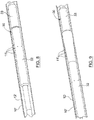
- the sheet 2 in order to apply the sheet 2 to the wall of the conduit, the sheet 2 is rolled up into a tubular rolled-up configuration, allowing the sheet to be inserted end-first into the conduit.
- the rolled-up lining In the rolled-up configuration, the rolled-up lining has a diameter that is smaller than that of the conduit to allow insertion.
- Figure 3 illustrates a typical such rolled-up configuration.
- a first section of the sheet 2 is turned into overlap within a second section of the sheet 2, and is provided with edge prongs 4 which contact against an inside of the second section.
- the edge prongs 4 help to increase the flexibility of the sheet 2 in the first section, and can help both to prevent crinkling and to curl and roll up the sheet 2 evenly into the roll configuration.
- the sheet 2 is rolled up with the applied adhesive 3a, 3b faced outwardly in the tubular roll.
- the applied adhesive 3a, 3b sticks to and stays in place on the surface of the sheet 2 after it is applied, and during rolling, such that the adhesive does not stick to overlapping sections of the sheet 2 which are curled around and brought into contact with the adhesive as the rolling-up process progresses.
- the sheet 2 is inserted into the conduit, and with reference now additionally to Figures 4 and 5 , an example such a conduit is illustrated in the form of a pipe 10 which is to be lined using the sheet 2.
- the pipe 10 has two openings 11a, 11b which extend through a wall 12 of the pipe 10. These openings may for instance allow fluid access between an interior of the pipe 10 and a region outside of the pipe 10.
- the rolled up sheet 2 is positioned in the desired location adjacent to the openings 11a, 11b, and is then allowed to unroll somewhat such that the sheet 2 is brought into position against the wall 12, covering over the openings 11a, 11b, as indicated in Figure 5 .
- the sheet 2 unrolls by itself due to the inherent resilience in the material of the sheet 2 upon being free to unroll or unravel from the initial rolled up configuration.
- the sheet 2 can be inserted in any convenient way, for example with the assistance of an inserter tool which holds the sheet 1 in the initial rolled up configuration during insertion and from which the sheet 2 can be released, but it will be appreciated that in other variants or in particular contexts, the rolled-up sheet 2 may be prepared in some other way to allow the sheet to unroll by itself when inside the conduit, or may for example be deployed by hand, depending upon the application.
- the sections of the sheet 2 can self-position against the wall 12 of the pipe 10, and can adapt to the internal diameter of the pipe.
- the sheet partially unrolls under a resilience force of the sheet and expands diametrically so that it is urged against the wall 12.
- the adhesive 3a, 3b activates and sets, such that the sheet 2 is secured to the wall 12 by means of the adhesive 3a, 3b, and forms a laminate on the wall of the wellbore.
- the adhesive 3a, 3b functions as part of the laminate both to adhere the sheet 2 in place and provide a fluid-tight seal between the sheet 2 and the wall 12.
- the adhesive 3b forms a bond between the wall of the wellbore and an outside of the sheet 2, and the adhesive 3a forms a bond between overlapping sections of the sheet 2.
- the adhesive 3a, 3b Upon exceeding the activation temperature, the adhesive 3a, 3b typically softens before setting and bonding.
- a typical configuration of the sheet 2 after expansion inside the pipe 10 is illustrated where sections of the sheet 2 overlap and a thin laminate 8 is produced on the wall 12 of the pipe 10.
- the laminate 8 is formed on the wall 12 of the pipe by a layering of curved overlapping sections of the steel sheet 2 and the adhesive 3a, 3b.
- the laminate 8 thus provides a liner structure that is well bonded and sealed to the pipe 10 and can isolate between the interior of the pipe 10 and a region behind the wall 12.
- FIG. 8 to 10 a process of applying the sheet 2 to a wall of a wellbore tubular 10' is illustrated, the process being carried out with the assistance of an inserter tool 30.
- the inserter tool 30 is connected to a string which is run into the wellbore from the surface, e.g. on a wireline, or coiled tubing or the like.
- the sheet 2 is rolled up around a mandrel 31 of the inserter tool 30, and is retained in the rolled up configuration by upper and lower retainer sleeves 32, 33 which are operable to retain the sheet 2 in the rolled up configuration.
- the sheet 2 is housed within the first and second retainer sleeves 32, 33, preventing radial expansion of the sheet 2 onto the wall, until the sheet 2 is brought into the desired position inside the tubing 10'.
- the sheet 2 is being released from the inserter tool 30.
- the first retainer sleeve 32 is moved uphole along the mandrel 31 away from the second retainer sleeve 33.
- a lower end of the rolled-up sheet 2 becomes exposed to the wellbore, and begins to unravel and expand resiliently toward the wall 12' of wellbore tubing 10'.
- the first retainer sleeve 32 is fully retracted along the mandrel 31, allowing the other end of the rolled up sheet 2 to release.
- the lining 1 has partially unrolled into engagement with the wall 12' of the wellbore tubing 10', covering over previously formed holes 11' in the wall 12'.
- the adhesive 3a, 3b on the sheet 2 then activates to secure and seal the sheet 2 in place on the wall 12' and form a laminate.
- the first and second retainer sleeves 32, 33 are movably mounted on the mandrel 31, and are moved apart by hydraulic fluid pushing on a reaction surface on either or both of the sleeves 32, 33.
- the inserter tool 30 may be activated through a signal delivered though an electrical cable to operate a hydraulic or electric actuator so that the retainer sleeves 32, 33 are driven to either side. It will be appreciated that other actuation mechanisms may be employed and/or other kinds of retainers.
- the use of retainer sleeves 32, 33 as shown may be beneficial in that the lining 1 can be protected somewhat from the wellbore environment until the desired installation location in the wellbore is reached.
- the sheet 2 can comprise a flexible spring steel sheet with an average total thickness dimension of around 0.25 mm, and the surface of the wall to which the sheet is applied may also comprise steel, such as that typical of casing sections used in a wellbore.
- the adhesive 3a, 3b is prepared by mixing together constituent components of the adhesive at a temperature above 50 °C, at which temperature the mixture has a liquid consistency allowing the components to be readily stirred and mixed.
- the mixture is spread over the sheet 2 (whilst still heated above 50 °C) in liquid form, and is left to cool down so that the mixture begins to "dry” and forms a thin film of adhesive on the steel sheet.
- the adhesive 3b in the section which is intended to form a seal against the wall of the tubular is applied more thickly, and may typically have a thickness of approximately 1 to 3 mm.
- the adhesive becomes a highly viscous non-sticky fluid with a degree of flexibility.
- the sheet 2 with the applied adhesive 3a, 3b is rolled up, while the adhesive 3a, 3b remains highly flexible and complies with the deformation and flexure of the sheet 2 as it is rolled or curled up (and/or when unrolled or uncurled).
- the sheet 2 can thus be rolled up with the applied adhesive 3a, 3b and placed into the inserter tool 30.
- the temperature may typically increase above 50 °C which will activate the adhesive.
- the adhesive 3a, 3b then softens (becomes a low-viscous fluid), and sets to secure and adhere the sheet in place on the wall of the wellbore, and forming a seal between an outside of the sheet and the wall.
- the adhesive may be sufficiently viscous to prevent flow under gravity.
- the adhesive setting process can commence when remaining above the activation temperature for a certain pre-defined period of time. The onset of the setting process for the adhesive 3a, 3b can be adjusted, e.g. by the choice of the constituent components mixed into the adhesive.
- the onset of the setting process can be delayed by for example 1 to 10 hours after being exposed to a temperature above 50 °C.
- the adhesive 3a, 3b is configured so that the setting process does not take place before the steel sheet 2 has been released onto the wall of the wellbore. This can help to allow the sheet to unroll into place on the wall without the adhesive adversely interfering with the unrolling of the sheet 2.
- the adhesive may be a thermosetting adhesive.
- the adhesive may for example comprise epoxy resin.
- the adhesive may be of another type such as any of those adhesives described elsewhere herein.
- the sheet may be provided with a sealer in addition to or in place of the adhesive.
- the sealer may be provided on the sheet and be rolled up with the sheet into a rolled configuration. Then, once inserted into the conduit, the sheet may unroll to produce a laminate and the sealer may be placed between the sheet and the wall of the conduit and seal therebetween, and held in place by the sheet of the laminate.
- the sealer may be in the form of a strip of rubber or swellable material provided on a surface of the sheet. The sheet may otherwise be deployed and applied to the wall of a conduit in a corresponding manner to that of the sheet 2 as described above.
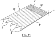
- a piece of material 1' in the form of steel sheet 2' is illustrated where a structure 9' is provided on part of the sheet for reinforcing the laminate which is produced when applying the sheet to an internal wall of a conduit.
- the structure 9' in this example is illustrated in the form of netting. In other variants, the structure can 9' can have other forms such as a sponge or webbing.
- Adhesive 3a' is provided on one part of the sheet 2', and a further amount of adhesive 3b' is embedded in the structure 9' on another part of the sheet 2'.
- the adhesive 3b' and structure 9' is on the part of the sheet which is placed outermost in the rolled up sheet for facing the internal wall of the conduit to be lined.
- the structure 9' may help to give stability and strength to the sheet 2' to support it in position against the wall. It will be appreciated that the piece of material 1' can be applied in the same manner as that of the piece of material 1 in the embodiments described above, and the adhesive 3a', 3b' may have the same properties as the adhesive 3a, 3b.
- the part of the sheet 2' with the structure 9' with the embedded adhesive 3b' may instead comprise a sealer, such as an elastomer seal or swellable material for sealing against the wall, to be positioned between the outermost part of the piece of material and the internal wall of the conduit when deployed in the conduit. Sealing by use of the sealer can be beneficial for fluid and pressure containment in the conduit.
- a sealer such as an elastomer seal or swellable material for sealing against the wall
Landscapes
- Engineering & Computer Science (AREA)
- General Engineering & Computer Science (AREA)
- Mining & Mineral Resources (AREA)
- Life Sciences & Earth Sciences (AREA)
- Geology (AREA)
- Mechanical Engineering (AREA)
- Fluid Mechanics (AREA)
- Environmental & Geological Engineering (AREA)
- Physics & Mathematics (AREA)
- General Life Sciences & Earth Sciences (AREA)
- Geochemistry & Mineralogy (AREA)
- Lining Or Joining Of Plastics Or The Like (AREA)
- Laminated Bodies (AREA)
- Protection Of Pipes Against Damage, Friction, And Corrosion (AREA)
Claims (8)
- Un procédé de revêtement d'au moins une partie d'une paroi interne (12) d'un conduit de trou de forage, le procédé comprenant les étapes consistant à :(a) fournir au moins une pièce de matériau (1) à appliquer sur la paroi interne (12) du conduit de trou de forage, la pièce de matériau (1) ayant un épaisseur (T) dans la plage de 0.1 mm à 0.4 mm;(b) appliquer un adhésif (3a, 3b) sur la pièce de matériau (1), subséquemment enroulant ou courbant la pièce de matériau (1) avec l'adhésif (3a, 3b) appliqué sur celle-ci, et fournissant la pièce de matériau (1) enroulée ou courbée sur un outil d'insertion (30);(c) insérer l'outil d'insertion (30) avec la pièce de matériau (1) enroulée ou courbée dans le conduit et entrainer l'outil d'insertion (30) dans le conduit pour y positionner le matériau (1) enroulé ou courbé ; et(d) libérer la pièce de matériau (1) de l'outil d'insertion (30), afin de laisser la pièce de matériau (1) se dérouler ou se redresser au moins partiellement, permettant à la pièce de matériau (1) insérée de se dérouler ou se redresser au moins partiellement à l'intérieur du conduit, en utilisant l'adhésif (3a, 3b) pour fixer la pièce de matériau (1) en place, de manière à appliquer le matériau et obtenir un stratifié (8) qui forme une doublure sur ladite partie de la paroi interne (12) du conduit;dans lequel la pièce de matériau (1) est configurée pour être flexible et résiliente, de sorte qu'à l'étape d la pièce de matériau (1) exerce une composante de force élastique en réponse à l'enroulement ou à la courbure par laquelle la pièce de matériau (1) est sollicitée pour se dérouler ou se redresser au moins partiellement à l'intérieur du conduit, afin d'appliquer le matériau et d'obtenir le stratifié (8) sur ladite partie de la paroi interne (12) du conduit;
dans lequel le stratifié (8) comprend une combinaison d'adhésif (3a, 3b) et de sections de pièce de matériau (1) se chevauchant;
dans lequel l'outil d'insertion (30) comprend:un mandrin (31) pour supporter la pièce de matériau (1) dans la configuration enroulée ou courbée autour du mandrin (31); etau moins un élément de retenue agencé pour retenir la pièce de matériau (1) dans la configuration enroulée ou courbée pendant l'insertion. - Un procédé selon la revendication 1, dans lequel en permettant à la pièce de matériau (1) insérée de se dérouler ou de se redresser au moins partiellement à l'intérieur du conduit, la pièce de matériau (1) est positionnée sur la partie de la paroi interne (12) du conduit, de sorte que lorsqu'elle est positionnée une section de la pièce de matériau (1) chevauche au moins une autre section de la pièce de matériau (1), moyennant quoi la pièce de matériau (1) est disposée en couches sur la paroi (12) du conduit où les sections se chevauchent, et le stratifié (8) comprend une combinaison d'adhésif (3a, 3b) et des couches.
- Un procédé selon l'une quelconque des revendications précédentes1 ou 2, dans lequel la pièce de matériau (1) comprend une tôle d'acier à ressort (2).
- Un procédé selon l'une quelconque des revendications précédentes, dans lequel la pièce de matériau (1) a des bords à dents, les bords à dents s'engageant avec une section chevauchante de la pièce de matériau (1) ou de la paroi interne (12) du conduit pour faciliter la performance de l'un ou des deux : i) enrouler ou courber la doublure; et ii) le déroulement ou le redressement partiel de la pièce de matériau.
- Un procédé selon l'une quelconque des revendications précédentes, dans lequel le stratifié (8) a une épaisseur dans la plage de 0,10 et 3,00 mm.
- Un procédé selon l'une quelconque des revendications précédentes, dans lequel l'adhésif (3a, 3b) est fourni sur un ou les deux côtés de la pièce de matériau (1).
- Le procédé selon l'une quelconque des revendications précédentes, dans lequel l'adhésif (3a, 3b) est pressé contre la paroi (12) et en outre utilisé à l'étape d pour sceller entre la pièce de matériau (1) et ladite partie de la paroi interne (12) du conduit.
- Un procédé selon l'une quelconque des revendications précédentes, qui comprend en outre: fournir un élément chauffant en tant que partie de l'outil d'insertion (30) ; et lorsque l'outil d'insertion (30) est inséré à l'intérieur du conduit, utiliser l'élément chauffant pour chauffer la pièce de matériau (1) pour durcir ou post-durcir l'adhésif (3a, 3b), de manière à utiliser l'adhésif (3a, 3b) pour fixer la pièce de matériau (1) en place.
Applications Claiming Priority (2)
| Application Number | Priority Date | Filing Date | Title |
|---|---|---|---|
| NO20160313A NO341973B1 (en) | 2016-02-24 | 2016-02-24 | Improvements relating to lining an internal wall of a conduit |
| PCT/NO2017/050051 WO2017146593A1 (fr) | 2016-02-24 | 2017-02-23 | Appareil et procédé de revêtement de paroi interne de conduit |
Publications (2)
| Publication Number | Publication Date |
|---|---|
| EP3420183A1 EP3420183A1 (fr) | 2019-01-02 |
| EP3420183B1 true EP3420183B1 (fr) | 2021-11-10 |
Family
ID=58428330
Family Applications (1)
| Application Number | Title | Priority Date | Filing Date |
|---|---|---|---|
| EP17714031.6A Active EP3420183B1 (fr) | 2016-02-24 | 2017-02-23 | Appareil et procédé de revêtement de paroi interne de conduit |
Country Status (6)
| Country | Link |
|---|---|
| US (1) | US10808876B2 (fr) |
| EP (1) | EP3420183B1 (fr) |
| DK (1) | DK3420183T3 (fr) |
| NO (1) | NO341973B1 (fr) |
| SA (1) | SA518392256B1 (fr) |
| WO (1) | WO2017146593A1 (fr) |
Families Citing this family (48)
| Publication number | Priority date | Publication date | Assignee | Title |
|---|---|---|---|---|
| US10934814B2 (en) * | 2018-06-06 | 2021-03-02 | Saudi Arabian Oil Company | Liner installation with inflatable packer |
| US10767452B2 (en) | 2018-06-06 | 2020-09-08 | Saudi Arabian Oil Company | Liner installation with inflatable packer |
| CN109236186B (zh) * | 2018-10-30 | 2020-03-06 | 中国石油大学(华东) | 钻井套管及大井眼多分支井快速钻完井方法 |
| US11346177B2 (en) | 2019-12-04 | 2022-05-31 | Saudi Arabian Oil Company | Repairable seal assemblies for oil and gas applications |
| US11261678B2 (en) | 2019-12-10 | 2022-03-01 | Saudi Arabian Oil Company | Deploying wellbore patch for mitigating lost circulation |
| US11668143B2 (en) | 2019-12-10 | 2023-06-06 | Saudi Arabian Oil Company | Deploying wellbore patch for mitigating lost circulation |
| US11125046B2 (en) | 2019-12-10 | 2021-09-21 | Saudi Arabian Oil Company | Deploying wellbore patch for mitigating lost circulation |
| BR112022018077A2 (pt) | 2020-03-23 | 2022-10-25 | Isealate As | Ferramenta de assentamento para um aparelho de fundo de poço para reparar uma parede de um conduto e um método de reparar um conduto |
| US11643878B2 (en) | 2020-03-26 | 2023-05-09 | Saudi Arabian Oil Company | Deploying material to limit losses of drilling fluid in a wellbore |
| US11286733B2 (en) | 2020-03-26 | 2022-03-29 | Saudi Arabian Oil Company | Deploying material to limit losses of drilling fluid in a wellbore |
| US11454071B2 (en) | 2020-03-26 | 2022-09-27 | Saudi Arabian Oil Company | Deploying material to limit losses of drilling fluid in a wellbore |
| US11339636B2 (en) | 2020-05-04 | 2022-05-24 | Saudi Arabian Oil Company | Determining the integrity of an isolated zone in a wellbore |
| US11414985B2 (en) | 2020-05-28 | 2022-08-16 | Saudi Arabian Oil Company | Measuring wellbore cross-sections using downhole caliper tools |
| US11414984B2 (en) | 2020-05-28 | 2022-08-16 | Saudi Arabian Oil Company | Measuring wellbore cross-sections using downhole caliper tools |
| US11631884B2 (en) | 2020-06-02 | 2023-04-18 | Saudi Arabian Oil Company | Electrolyte structure for a high-temperature, high-pressure lithium battery |
| US11149510B1 (en) | 2020-06-03 | 2021-10-19 | Saudi Arabian Oil Company | Freeing a stuck pipe from a wellbore |
| US11391104B2 (en) | 2020-06-03 | 2022-07-19 | Saudi Arabian Oil Company | Freeing a stuck pipe from a wellbore |
| US11434707B2 (en) | 2020-06-10 | 2022-09-06 | Saudi Arabian Oil Company | Lost circulation fabric, method, and deployment systems |
| US11434708B2 (en) | 2020-06-10 | 2022-09-06 | Saudi Arabian Oil Company | Lost circulation fabric, method, and deployment systems |
| US11459838B2 (en) | 2020-06-10 | 2022-10-04 | Saudi Arabian Oil Company | Lost circulation fabric, method, and deployment systems |
| US11719089B2 (en) | 2020-07-15 | 2023-08-08 | Saudi Arabian Oil Company | Analysis of drilling slurry solids by image processing |
| US11255130B2 (en) | 2020-07-22 | 2022-02-22 | Saudi Arabian Oil Company | Sensing drill bit wear under downhole conditions |
| US11506044B2 (en) | 2020-07-23 | 2022-11-22 | Saudi Arabian Oil Company | Automatic analysis of drill string dynamics |
| US11920469B2 (en) | 2020-09-08 | 2024-03-05 | Saudi Arabian Oil Company | Determining fluid parameters |
| US11519767B2 (en) | 2020-09-08 | 2022-12-06 | Saudi Arabian Oil Company | Determining fluid parameters |
| US11867008B2 (en) | 2020-11-05 | 2024-01-09 | Saudi Arabian Oil Company | System and methods for the measurement of drilling mud flow in real-time |
| US11434714B2 (en) | 2021-01-04 | 2022-09-06 | Saudi Arabian Oil Company | Adjustable seal for sealing a fluid flow at a wellhead |
| US11697991B2 (en) | 2021-01-13 | 2023-07-11 | Saudi Arabian Oil Company | Rig sensor testing and calibration |
| US11530597B2 (en) | 2021-02-18 | 2022-12-20 | Saudi Arabian Oil Company | Downhole wireless communication |
| US11572752B2 (en) | 2021-02-24 | 2023-02-07 | Saudi Arabian Oil Company | Downhole cable deployment |
| US11727555B2 (en) | 2021-02-25 | 2023-08-15 | Saudi Arabian Oil Company | Rig power system efficiency optimization through image processing |
| US11603756B2 (en) | 2021-03-03 | 2023-03-14 | Saudi Arabian Oil Company | Downhole wireless communication |
| US11846151B2 (en) | 2021-03-09 | 2023-12-19 | Saudi Arabian Oil Company | Repairing a cased wellbore |
| US11644351B2 (en) | 2021-03-19 | 2023-05-09 | Saudi Arabian Oil Company | Multiphase flow and salinity meter with dual opposite handed helical resonators |
| US11913464B2 (en) | 2021-04-15 | 2024-02-27 | Saudi Arabian Oil Company | Lubricating an electric submersible pump |
| US11619114B2 (en) | 2021-04-15 | 2023-04-04 | Saudi Arabian Oil Company | Entering a lateral branch of a wellbore with an assembly |
| CN113738271A (zh) * | 2021-08-04 | 2021-12-03 | 中煤科工集团西安研究院有限公司 | 一种煤矿井下松软煤层膨胀式割缝管完孔方法 |
| NO20211086A1 (en) * | 2021-09-09 | 2023-03-10 | Isealate As | Sand screens and related products and methods |
| CN113606424A (zh) * | 2021-09-14 | 2021-11-05 | 泉州师范学院 | 一种下水道渗水快速修复卡片及修复方法 |
| US11624265B1 (en) | 2021-11-12 | 2023-04-11 | Saudi Arabian Oil Company | Cutting pipes in wellbores using downhole autonomous jet cutting tools |
| US11867012B2 (en) | 2021-12-06 | 2024-01-09 | Saudi Arabian Oil Company | Gauge cutter and sampler apparatus |
| US11994016B2 (en) | 2021-12-09 | 2024-05-28 | Saudi Arabian Oil Company | Downhole phase separation in deviated wells |
| US11643801B1 (en) * | 2021-12-29 | 2023-05-09 | Gulf Coast Underground, LLC | System and method for sealing an annular space of a sewer connection line |
| US12085687B2 (en) | 2022-01-10 | 2024-09-10 | Saudi Arabian Oil Company | Model-constrained multi-phase virtual flow metering and forecasting with machine learning |
| EP4290047A1 (fr) * | 2022-06-10 | 2023-12-13 | Isealate AS | Ensemble tubulaire extensible de fond de trou |
| US12209470B2 (en) | 2022-11-17 | 2025-01-28 | Wireless Instrumentation Systems AS | Woven sleeves and related methods of constraining a well tool |
| US12203366B2 (en) | 2023-05-02 | 2025-01-21 | Saudi Arabian Oil Company | Collecting samples from wellbores |
| US12492600B2 (en) * | 2024-05-23 | 2025-12-09 | Saudi Arabian Oil Company | Expandable wellbore loss control patch |
Family Cites Families (15)
| Publication number | Priority date | Publication date | Assignee | Title |
|---|---|---|---|---|
| GB1026162A (en) * | 1962-02-12 | 1966-04-14 | Schermuly Ltd | Improvements in pyrotechnic devices |
| GB1594573A (en) * | 1976-11-05 | 1981-07-30 | Raychem Sa Nv | Sealing and insulating heat-recoverable article and method |
| US5119862A (en) * | 1988-10-31 | 1992-06-09 | Link-Pipe Technlogies, Inc. | Conduit repair apparatus |
| CH682945A5 (de) * | 1989-12-01 | 1993-12-15 | Sika Robotics Ag | Ferngesteuerter Schalungseinbau in nicht begehbaren Rohrverzweigungen und Einmündungen. |
| US5186215A (en) * | 1989-08-01 | 1993-02-16 | Cues, Inc. | Apparatus for repairing pipelines |
| TW347455B (en) * | 1995-11-09 | 1998-12-11 | Link Pipe Inc | Conduit lining system and method of lining a conduit |
| US5971030A (en) * | 1997-06-06 | 1999-10-26 | Maimets; Lembit | Apparatus and method for repairing pressure pipes and for securing other elements with a curable sealant |
| FR2765619B1 (fr) * | 1997-07-01 | 2000-10-06 | Schlumberger Cie Dowell | Procede et dispositif pour la completion de puits pour la production d'hydrocarbures ou analogues |
| EP0899420A1 (fr) * | 1997-08-27 | 1999-03-03 | Shell Internationale Researchmaatschappij B.V. | Procédé pour la mise en place d'une feuille souple enroulée le long de la surface intérieure d'un conduit de fluide |
| DE19741665A1 (de) * | 1997-09-16 | 1998-03-26 | Wolfgang Kuehnau | Element und Verfahren zur Sanierung von runden Abwasserrohren von 150 bis 600 mm Durchmesser |
| DE19835316A1 (de) | 1998-08-05 | 2000-02-10 | Bosch Gmbh Robert | Gesteuerte Gleichrichterbrücke mit Überspannungsschutz |
| US6138718A (en) * | 1998-10-30 | 2000-10-31 | Link-Pipe (H. K.), Ltd. | Apparatus and method for repairing pressure pipes |
| WO2007106429A2 (fr) * | 2006-03-10 | 2007-09-20 | Dynamic Tubular Systems, Inc. | Elements tubulaires extensibles pour structures geologiques |
| US20090314409A1 (en) * | 2008-06-18 | 2009-12-24 | Ehsani Mohammad R | Apparatus and Method of Reinforcing a Conduit or Vessel |
| US10386006B2 (en) * | 2017-08-18 | 2019-08-20 | Sanexen Environmental Services Inc. | Method and apparatus for rehabilitation of water conduit with lateral openings |
-
2016
- 2016-02-24 NO NO20160313A patent/NO341973B1/en unknown
-
2017
- 2017-02-23 EP EP17714031.6A patent/EP3420183B1/fr active Active
- 2017-02-23 WO PCT/NO2017/050051 patent/WO2017146593A1/fr not_active Ceased
- 2017-02-23 DK DK17714031.6T patent/DK3420183T3/da active
- 2017-02-23 US US16/078,691 patent/US10808876B2/en active Active
-
2018
- 2018-08-22 SA SA518392256A patent/SA518392256B1/ar unknown
Non-Patent Citations (2)
| Title |
|---|
| "'spring loaded' pipe lining system", REINFORCED PLASTICS, ELSEVIER ADVANCED TECHNOLOGY, NEW YORK, NY, US, vol. 53, no. 6, 1 August 2009 (2009-08-01), pages 14, XP026715768, ISSN: 0034-3617, [retrieved on 20090801], DOI: 10.1016/S0034-3617(09)70248-6 * |
| QUAKEWRAP: "PipeMedic bridges the gap in a pressurized pipe", YOUTUBE, 12 August 2010 (2010-08-12), XP055659761, Retrieved from the Internet <URL:https://www.youtube.com/watch?v=QnO2y3TZDgk> [retrieved on 20200120] * |
Also Published As
| Publication number | Publication date |
|---|---|
| NO341973B1 (en) | 2018-03-05 |
| DK3420183T3 (en) | 2022-01-31 |
| SA518392256B1 (ar) | 2023-01-04 |
| US10808876B2 (en) | 2020-10-20 |
| EP3420183A1 (fr) | 2019-01-02 |
| WO2017146593A1 (fr) | 2017-08-31 |
| US20190049054A1 (en) | 2019-02-14 |
| NO20160313A1 (en) | 2017-08-25 |
Similar Documents
| Publication | Publication Date | Title |
|---|---|---|
| EP3420183B1 (fr) | Appareil et procédé de revêtement de paroi interne de conduit | |
| CA2366874C (fr) | Technique d'isolation de puits de forage | |
| EP4180621B1 (fr) | Installation de doublure avec garniture gonflable | |
| EP2024601B1 (fr) | Procédé et appareil permettant le rapiéçage d'un puits par hydroformage d'une pièce de rapiéçage métallique tubulaire, et pièce de rapiéçage à cette fin | |
| CA2834026C (fr) | Ancrage expansible de trou en decouvert | |
| CA2856678C (fr) | Outil d'isolement de puits de forage utilisant un element d'etancheification ayant un polymere a memoire de forme | |
| EP2312119A1 (fr) | Barrière annulaire | |
| AU2012220876B2 (en) | Expandable packer with expansion induced axially movable support feature | |
| CN102428248A (zh) | 膨胀封隔器以及构造方法 | |
| US20040108626A1 (en) | Expandable composite tubulars | |
| CA3053711C (fr) | Bouchon pour colonne de production concentrique | |
| US20150337617A1 (en) | Isolation Barrier | |
| EP4290047A1 (fr) | Ensemble tubulaire extensible de fond de trou | |
| US12291938B2 (en) | Running tool for a downhole aparatus for patching a wall of conduit and a method of patching a conduit | |
| US12492600B2 (en) | Expandable wellbore loss control patch | |
| US12497867B2 (en) | Sand screens and related products and methods | |
| EA051291B1 (ru) | Спускной инструмент для скважинного снаряда для наложения заплаты на стенку трубопровода и способ наложения заплаты на трубопровод | |
| AU2008237556B2 (en) | Expandable composite tubulars | |
| US20150204160A1 (en) | Isolation Barrier |
Legal Events
| Date | Code | Title | Description |
|---|---|---|---|
| STAA | Information on the status of an ep patent application or granted ep patent |
Free format text: STATUS: UNKNOWN |
|
| STAA | Information on the status of an ep patent application or granted ep patent |
Free format text: STATUS: THE INTERNATIONAL PUBLICATION HAS BEEN MADE |
|
| PUAI | Public reference made under article 153(3) epc to a published international application that has entered the european phase |
Free format text: ORIGINAL CODE: 0009012 |
|
| STAA | Information on the status of an ep patent application or granted ep patent |
Free format text: STATUS: REQUEST FOR EXAMINATION WAS MADE |
|
| 17P | Request for examination filed |
Effective date: 20180817 |
|
| AK | Designated contracting states |
Kind code of ref document: A1 Designated state(s): AL AT BE BG CH CY CZ DE DK EE ES FI FR GB GR HR HU IE IS IT LI LT LU LV MC MK MT NL NO PL PT RO RS SE SI SK SM TR |
|
| AX | Request for extension of the european patent |
Extension state: BA ME |
|
| DAV | Request for validation of the european patent (deleted) | ||
| DAX | Request for extension of the european patent (deleted) | ||
| STAA | Information on the status of an ep patent application or granted ep patent |
Free format text: STATUS: EXAMINATION IS IN PROGRESS |
|
| 17Q | First examination report despatched |
Effective date: 20200127 |
|
| RIN1 | Information on inventor provided before grant (corrected) |
Inventor name: GUNNARSON, BENGT Inventor name: WAAGE-RASMUSSEN, EINAR Inventor name: FORSSTROEM, DAN Inventor name: HAASUM, JOHAN |
|
| GRAP | Despatch of communication of intention to grant a patent |
Free format text: ORIGINAL CODE: EPIDOSNIGR1 |
|
| STAA | Information on the status of an ep patent application or granted ep patent |
Free format text: STATUS: GRANT OF PATENT IS INTENDED |
|
| INTG | Intention to grant announced |
Effective date: 20210607 |
|
| GRAS | Grant fee paid |
Free format text: ORIGINAL CODE: EPIDOSNIGR3 |
|
| GRAA | (expected) grant |
Free format text: ORIGINAL CODE: 0009210 |
|
| STAA | Information on the status of an ep patent application or granted ep patent |
Free format text: STATUS: THE PATENT HAS BEEN GRANTED |
|
| AK | Designated contracting states |
Kind code of ref document: B1 Designated state(s): AL AT BE BG CH CY CZ DE DK EE ES FI FR GB GR HR HU IE IS IT LI LT LU LV MC MK MT NL NO PL PT RO RS SE SI SK SM TR |
|
| REG | Reference to a national code |
Ref country code: GB Ref legal event code: FG4D |
|
| REG | Reference to a national code |
Ref country code: AT Ref legal event code: REF Ref document number: 1446279 Country of ref document: AT Kind code of ref document: T Effective date: 20211115 Ref country code: CH Ref legal event code: EP |
|
| REG | Reference to a national code |
Ref country code: DE Ref legal event code: R096 Ref document number: 602017049068 Country of ref document: DE |
|
| REG | Reference to a national code |
Ref country code: IE Ref legal event code: FG4D |
|
| REG | Reference to a national code |
Ref country code: DK Ref legal event code: T3 Effective date: 20220128 |
|
| REG | Reference to a national code |
Ref country code: NL Ref legal event code: FP |
|
| REG | Reference to a national code |
Ref country code: LT Ref legal event code: MG9D |
|
| REG | Reference to a national code |
Ref country code: AT Ref legal event code: MK05 Ref document number: 1446279 Country of ref document: AT Kind code of ref document: T Effective date: 20211110 |
|
| PG25 | Lapsed in a contracting state [announced via postgrant information from national office to epo] |
Ref country code: RS Free format text: LAPSE BECAUSE OF FAILURE TO SUBMIT A TRANSLATION OF THE DESCRIPTION OR TO PAY THE FEE WITHIN THE PRESCRIBED TIME-LIMIT Effective date: 20211110 Ref country code: LT Free format text: LAPSE BECAUSE OF FAILURE TO SUBMIT A TRANSLATION OF THE DESCRIPTION OR TO PAY THE FEE WITHIN THE PRESCRIBED TIME-LIMIT Effective date: 20211110 Ref country code: FI Free format text: LAPSE BECAUSE OF FAILURE TO SUBMIT A TRANSLATION OF THE DESCRIPTION OR TO PAY THE FEE WITHIN THE PRESCRIBED TIME-LIMIT Effective date: 20211110 Ref country code: BG Free format text: LAPSE BECAUSE OF FAILURE TO SUBMIT A TRANSLATION OF THE DESCRIPTION OR TO PAY THE FEE WITHIN THE PRESCRIBED TIME-LIMIT Effective date: 20220210 Ref country code: AT Free format text: LAPSE BECAUSE OF FAILURE TO SUBMIT A TRANSLATION OF THE DESCRIPTION OR TO PAY THE FEE WITHIN THE PRESCRIBED TIME-LIMIT Effective date: 20211110 |
|
| PG25 | Lapsed in a contracting state [announced via postgrant information from national office to epo] |
Ref country code: IS Free format text: LAPSE BECAUSE OF FAILURE TO SUBMIT A TRANSLATION OF THE DESCRIPTION OR TO PAY THE FEE WITHIN THE PRESCRIBED TIME-LIMIT Effective date: 20220310 Ref country code: SE Free format text: LAPSE BECAUSE OF FAILURE TO SUBMIT A TRANSLATION OF THE DESCRIPTION OR TO PAY THE FEE WITHIN THE PRESCRIBED TIME-LIMIT Effective date: 20211110 Ref country code: PT Free format text: LAPSE BECAUSE OF FAILURE TO SUBMIT A TRANSLATION OF THE DESCRIPTION OR TO PAY THE FEE WITHIN THE PRESCRIBED TIME-LIMIT Effective date: 20220310 Ref country code: PL Free format text: LAPSE BECAUSE OF FAILURE TO SUBMIT A TRANSLATION OF THE DESCRIPTION OR TO PAY THE FEE WITHIN THE PRESCRIBED TIME-LIMIT Effective date: 20211110 Ref country code: NO Free format text: LAPSE BECAUSE OF FAILURE TO SUBMIT A TRANSLATION OF THE DESCRIPTION OR TO PAY THE FEE WITHIN THE PRESCRIBED TIME-LIMIT Effective date: 20220210 Ref country code: LV Free format text: LAPSE BECAUSE OF FAILURE TO SUBMIT A TRANSLATION OF THE DESCRIPTION OR TO PAY THE FEE WITHIN THE PRESCRIBED TIME-LIMIT Effective date: 20211110 Ref country code: HR Free format text: LAPSE BECAUSE OF FAILURE TO SUBMIT A TRANSLATION OF THE DESCRIPTION OR TO PAY THE FEE WITHIN THE PRESCRIBED TIME-LIMIT Effective date: 20211110 Ref country code: GR Free format text: LAPSE BECAUSE OF FAILURE TO SUBMIT A TRANSLATION OF THE DESCRIPTION OR TO PAY THE FEE WITHIN THE PRESCRIBED TIME-LIMIT Effective date: 20220211 Ref country code: ES Free format text: LAPSE BECAUSE OF FAILURE TO SUBMIT A TRANSLATION OF THE DESCRIPTION OR TO PAY THE FEE WITHIN THE PRESCRIBED TIME-LIMIT Effective date: 20211110 |
|
| PG25 | Lapsed in a contracting state [announced via postgrant information from national office to epo] |
Ref country code: SM Free format text: LAPSE BECAUSE OF FAILURE TO SUBMIT A TRANSLATION OF THE DESCRIPTION OR TO PAY THE FEE WITHIN THE PRESCRIBED TIME-LIMIT Effective date: 20211110 Ref country code: SK Free format text: LAPSE BECAUSE OF FAILURE TO SUBMIT A TRANSLATION OF THE DESCRIPTION OR TO PAY THE FEE WITHIN THE PRESCRIBED TIME-LIMIT Effective date: 20211110 Ref country code: RO Free format text: LAPSE BECAUSE OF FAILURE TO SUBMIT A TRANSLATION OF THE DESCRIPTION OR TO PAY THE FEE WITHIN THE PRESCRIBED TIME-LIMIT Effective date: 20211110 Ref country code: EE Free format text: LAPSE BECAUSE OF FAILURE TO SUBMIT A TRANSLATION OF THE DESCRIPTION OR TO PAY THE FEE WITHIN THE PRESCRIBED TIME-LIMIT Effective date: 20211110 Ref country code: CZ Free format text: LAPSE BECAUSE OF FAILURE TO SUBMIT A TRANSLATION OF THE DESCRIPTION OR TO PAY THE FEE WITHIN THE PRESCRIBED TIME-LIMIT Effective date: 20211110 |
|
| REG | Reference to a national code |
Ref country code: DE Ref legal event code: R097 Ref document number: 602017049068 Country of ref document: DE |
|
| PLBE | No opposition filed within time limit |
Free format text: ORIGINAL CODE: 0009261 |
|
| STAA | Information on the status of an ep patent application or granted ep patent |
Free format text: STATUS: NO OPPOSITION FILED WITHIN TIME LIMIT |
|
| PG25 | Lapsed in a contracting state [announced via postgrant information from national office to epo] |
Ref country code: MC Free format text: LAPSE BECAUSE OF FAILURE TO SUBMIT A TRANSLATION OF THE DESCRIPTION OR TO PAY THE FEE WITHIN THE PRESCRIBED TIME-LIMIT Effective date: 20211110 |
|
| REG | Reference to a national code |
Ref country code: CH Ref legal event code: PL |
|
| 26N | No opposition filed |
Effective date: 20220811 |
|
| REG | Reference to a national code |
Ref country code: BE Ref legal event code: MM Effective date: 20220228 |
|
| PG25 | Lapsed in a contracting state [announced via postgrant information from national office to epo] |
Ref country code: LU Free format text: LAPSE BECAUSE OF NON-PAYMENT OF DUE FEES Effective date: 20220223 Ref country code: AL Free format text: LAPSE BECAUSE OF FAILURE TO SUBMIT A TRANSLATION OF THE DESCRIPTION OR TO PAY THE FEE WITHIN THE PRESCRIBED TIME-LIMIT Effective date: 20211110 |
|
| PG25 | Lapsed in a contracting state [announced via postgrant information from national office to epo] |
Ref country code: SI Free format text: LAPSE BECAUSE OF FAILURE TO SUBMIT A TRANSLATION OF THE DESCRIPTION OR TO PAY THE FEE WITHIN THE PRESCRIBED TIME-LIMIT Effective date: 20211110 |
|
| PG25 | Lapsed in a contracting state [announced via postgrant information from national office to epo] |
Ref country code: LI Free format text: LAPSE BECAUSE OF NON-PAYMENT OF DUE FEES Effective date: 20220228 Ref country code: IE Free format text: LAPSE BECAUSE OF NON-PAYMENT OF DUE FEES Effective date: 20220223 Ref country code: CH Free format text: LAPSE BECAUSE OF NON-PAYMENT OF DUE FEES Effective date: 20220228 |
|
| PG25 | Lapsed in a contracting state [announced via postgrant information from national office to epo] |
Ref country code: BE Free format text: LAPSE BECAUSE OF NON-PAYMENT OF DUE FEES Effective date: 20220228 |
|
| PG25 | Lapsed in a contracting state [announced via postgrant information from national office to epo] |
Ref country code: IT Free format text: LAPSE BECAUSE OF FAILURE TO SUBMIT A TRANSLATION OF THE DESCRIPTION OR TO PAY THE FEE WITHIN THE PRESCRIBED TIME-LIMIT Effective date: 20211110 |
|
| P01 | Opt-out of the competence of the unified patent court (upc) registered |
Effective date: 20230524 |
|
| PG25 | Lapsed in a contracting state [announced via postgrant information from national office to epo] |
Ref country code: HU Free format text: LAPSE BECAUSE OF FAILURE TO SUBMIT A TRANSLATION OF THE DESCRIPTION OR TO PAY THE FEE WITHIN THE PRESCRIBED TIME-LIMIT; INVALID AB INITIO Effective date: 20170223 |
|
| PG25 | Lapsed in a contracting state [announced via postgrant information from national office to epo] |
Ref country code: MK Free format text: LAPSE BECAUSE OF FAILURE TO SUBMIT A TRANSLATION OF THE DESCRIPTION OR TO PAY THE FEE WITHIN THE PRESCRIBED TIME-LIMIT Effective date: 20211110 Ref country code: CY Free format text: LAPSE BECAUSE OF FAILURE TO SUBMIT A TRANSLATION OF THE DESCRIPTION OR TO PAY THE FEE WITHIN THE PRESCRIBED TIME-LIMIT Effective date: 20211110 |
|
| PG25 | Lapsed in a contracting state [announced via postgrant information from national office to epo] |
Ref country code: MT Free format text: LAPSE BECAUSE OF FAILURE TO SUBMIT A TRANSLATION OF THE DESCRIPTION OR TO PAY THE FEE WITHIN THE PRESCRIBED TIME-LIMIT Effective date: 20211110 |
|
| PG25 | Lapsed in a contracting state [announced via postgrant information from national office to epo] |
Ref country code: TR Free format text: LAPSE BECAUSE OF FAILURE TO SUBMIT A TRANSLATION OF THE DESCRIPTION OR TO PAY THE FEE WITHIN THE PRESCRIBED TIME-LIMIT Effective date: 20211110 |
|
| PGFP | Annual fee paid to national office [announced via postgrant information from national office to epo] |
Ref country code: NL Payment date: 20260216 Year of fee payment: 10 |
|
| PGFP | Annual fee paid to national office [announced via postgrant information from national office to epo] |
Ref country code: GB Payment date: 20260210 Year of fee payment: 10 |
|
| PGFP | Annual fee paid to national office [announced via postgrant information from national office to epo] |
Ref country code: DE Payment date: 20260213 Year of fee payment: 10 Ref country code: DK Payment date: 20260210 Year of fee payment: 10 |
|
| PGFP | Annual fee paid to national office [announced via postgrant information from national office to epo] |
Ref country code: FR Payment date: 20260212 Year of fee payment: 10 |