EP3420424B1 - Procede d'execution d'un procede de production cyclique - Google Patents
Procede d'execution d'un procede de production cyclique Download PDFInfo
- Publication number
- EP3420424B1 EP3420424B1 EP17707494.5A EP17707494A EP3420424B1 EP 3420424 B1 EP3420424 B1 EP 3420424B1 EP 17707494 A EP17707494 A EP 17707494A EP 3420424 B1 EP3420424 B1 EP 3420424B1
- Authority
- EP
- European Patent Office
- Prior art keywords
- process parameter
- zone
- determined
- parameter
- production
- Prior art date
- Legal status (The legal status is an assumption and is not a legal conclusion. Google has not performed a legal analysis and makes no representation as to the accuracy of the status listed.)
- Active
Links
Images



Classifications
-
- B—PERFORMING OPERATIONS; TRANSPORTING
- B29—WORKING OF PLASTICS; WORKING OF SUBSTANCES IN A PLASTIC STATE IN GENERAL
- B29C—SHAPING OR JOINING OF PLASTICS; SHAPING OF MATERIAL IN A PLASTIC STATE, NOT OTHERWISE PROVIDED FOR; AFTER-TREATMENT OF THE SHAPED PRODUCTS, e.g. REPAIRING
- B29C45/00—Injection moulding, i.e. forcing the required volume of moulding material through a nozzle into a closed mould; Apparatus therefor
- B29C45/17—Component parts, details or accessories; Auxiliary operations
- B29C45/76—Measuring, controlling or regulating
- B29C45/766—Measuring, controlling or regulating the setting or resetting of moulding conditions, e.g. before starting a cycle
-
- B—PERFORMING OPERATIONS; TRANSPORTING
- B29—WORKING OF PLASTICS; WORKING OF SUBSTANCES IN A PLASTIC STATE IN GENERAL
- B29C—SHAPING OR JOINING OF PLASTICS; SHAPING OF MATERIAL IN A PLASTIC STATE, NOT OTHERWISE PROVIDED FOR; AFTER-TREATMENT OF THE SHAPED PRODUCTS, e.g. REPAIRING
- B29C45/00—Injection moulding, i.e. forcing the required volume of moulding material through a nozzle into a closed mould; Apparatus therefor
- B29C45/17—Component parts, details or accessories; Auxiliary operations
- B29C45/76—Measuring, controlling or regulating
-
- B—PERFORMING OPERATIONS; TRANSPORTING
- B29—WORKING OF PLASTICS; WORKING OF SUBSTANCES IN A PLASTIC STATE IN GENERAL
- B29C—SHAPING OR JOINING OF PLASTICS; SHAPING OF MATERIAL IN A PLASTIC STATE, NOT OTHERWISE PROVIDED FOR; AFTER-TREATMENT OF THE SHAPED PRODUCTS, e.g. REPAIRING
- B29C45/00—Injection moulding, i.e. forcing the required volume of moulding material through a nozzle into a closed mould; Apparatus therefor
- B29C45/17—Component parts, details or accessories; Auxiliary operations
- B29C45/76—Measuring, controlling or regulating
- B29C45/768—Detecting defective moulding conditions
-
- B—PERFORMING OPERATIONS; TRANSPORTING
- B29—WORKING OF PLASTICS; WORKING OF SUBSTANCES IN A PLASTIC STATE IN GENERAL
- B29C—SHAPING OR JOINING OF PLASTICS; SHAPING OF MATERIAL IN A PLASTIC STATE, NOT OTHERWISE PROVIDED FOR; AFTER-TREATMENT OF THE SHAPED PRODUCTS, e.g. REPAIRING
- B29C45/00—Injection moulding, i.e. forcing the required volume of moulding material through a nozzle into a closed mould; Apparatus therefor
- B29C45/17—Component parts, details or accessories; Auxiliary operations
- B29C45/76—Measuring, controlling or regulating
- B29C45/77—Measuring, controlling or regulating of velocity or pressure of moulding material
-
- B—PERFORMING OPERATIONS; TRANSPORTING
- B29—WORKING OF PLASTICS; WORKING OF SUBSTANCES IN A PLASTIC STATE IN GENERAL
- B29C—SHAPING OR JOINING OF PLASTICS; SHAPING OF MATERIAL IN A PLASTIC STATE, NOT OTHERWISE PROVIDED FOR; AFTER-TREATMENT OF THE SHAPED PRODUCTS, e.g. REPAIRING
- B29C45/00—Injection moulding, i.e. forcing the required volume of moulding material through a nozzle into a closed mould; Apparatus therefor
- B29C45/17—Component parts, details or accessories; Auxiliary operations
- B29C45/84—Safety devices
-
- G—PHYSICS
- G05—CONTROLLING; REGULATING
- G05B—CONTROL OR REGULATING SYSTEMS IN GENERAL; FUNCTIONAL ELEMENTS OF SUCH SYSTEMS; MONITORING OR TESTING ARRANGEMENTS FOR SUCH SYSTEMS OR ELEMENTS
- G05B19/00—Program-control systems
- G05B19/02—Program-control systems electric
- G05B19/418—Total factory control, i.e. centrally controlling a plurality of machines, e.g. direct or distributed numerical control [DNC], flexible manufacturing systems [FMS], integrated manufacturing systems [IMS] or computer integrated manufacturing [CIM]
- G05B19/41875—Total factory control, i.e. centrally controlling a plurality of machines, e.g. direct or distributed numerical control [DNC], flexible manufacturing systems [FMS], integrated manufacturing systems [IMS] or computer integrated manufacturing [CIM] characterised by quality surveillance of production
-
- B—PERFORMING OPERATIONS; TRANSPORTING
- B29—WORKING OF PLASTICS; WORKING OF SUBSTANCES IN A PLASTIC STATE IN GENERAL
- B29C—SHAPING OR JOINING OF PLASTICS; SHAPING OF MATERIAL IN A PLASTIC STATE, NOT OTHERWISE PROVIDED FOR; AFTER-TREATMENT OF THE SHAPED PRODUCTS, e.g. REPAIRING
- B29C2945/00—Indexing scheme relating to injection moulding, i.e. forcing the required volume of moulding material through a nozzle into a closed mould
- B29C2945/76—Measuring, controlling or regulating
- B29C2945/76929—Controlling method
- B29C2945/76939—Using stored or historical data sets
-
- B—PERFORMING OPERATIONS; TRANSPORTING
- B29—WORKING OF PLASTICS; WORKING OF SUBSTANCES IN A PLASTIC STATE IN GENERAL
- B29C—SHAPING OR JOINING OF PLASTICS; SHAPING OF MATERIAL IN A PLASTIC STATE, NOT OTHERWISE PROVIDED FOR; AFTER-TREATMENT OF THE SHAPED PRODUCTS, e.g. REPAIRING
- B29C2945/00—Indexing scheme relating to injection moulding, i.e. forcing the required volume of moulding material through a nozzle into a closed mould
- B29C2945/76—Measuring, controlling or regulating
- B29C2945/76929—Controlling method
- B29C2945/76939—Using stored or historical data sets
- B29C2945/76949—Using stored or historical data sets using a learning system, i.e. the system accumulates experience from previous occurrences, e.g. adaptive control
-
- G—PHYSICS
- G05—CONTROLLING; REGULATING
- G05B—CONTROL OR REGULATING SYSTEMS IN GENERAL; FUNCTIONAL ELEMENTS OF SUCH SYSTEMS; MONITORING OR TESTING ARRANGEMENTS FOR SUCH SYSTEMS OR ELEMENTS
- G05B2219/00—Program-control systems
- G05B2219/20—Pc systems
- G05B2219/26—Pc applications
- G05B2219/2624—Injection molding
-
- G—PHYSICS
- G05—CONTROLLING; REGULATING
- G05B—CONTROL OR REGULATING SYSTEMS IN GENERAL; FUNCTIONAL ELEMENTS OF SUCH SYSTEMS; MONITORING OR TESTING ARRANGEMENTS FOR SUCH SYSTEMS OR ELEMENTS
- G05B2219/00—Program-control systems
- G05B2219/30—Nc systems
- G05B2219/32—Operator till task planning
- G05B2219/32186—Teaching inspection data, pictures and criteria and apply them for inspection
-
- G—PHYSICS
- G05—CONTROLLING; REGULATING
- G05B—CONTROL OR REGULATING SYSTEMS IN GENERAL; FUNCTIONAL ELEMENTS OF SUCH SYSTEMS; MONITORING OR TESTING ARRANGEMENTS FOR SUCH SYSTEMS OR ELEMENTS
- G05B2219/00—Program-control systems
- G05B2219/30—Nc systems
- G05B2219/45—Nc applications
- G05B2219/45244—Injection molding
-
- Y—GENERAL TAGGING OF NEW TECHNOLOGICAL DEVELOPMENTS; GENERAL TAGGING OF CROSS-SECTIONAL TECHNOLOGIES SPANNING OVER SEVERAL SECTIONS OF THE IPC; TECHNICAL SUBJECTS COVERED BY FORMER USPC CROSS-REFERENCE ART COLLECTIONS [XRACs] AND DIGESTS
- Y02—TECHNOLOGIES OR APPLICATIONS FOR MITIGATION OR ADAPTATION AGAINST CLIMATE CHANGE
- Y02P—CLIMATE CHANGE MITIGATION TECHNOLOGIES IN THE PRODUCTION OR PROCESSING OF GOODS
- Y02P90/00—Enabling technologies with a potential contribution to greenhouse gas [GHG] emissions mitigation
- Y02P90/02—Total factory control, e.g. smart factories, flexible manufacturing systems [FMS] or integrated manufacturing systems [IMS]
Definitions
- the invention relates to a method for carrying out a cyclical production process according to the preamble of the independent claim.
- a cyclical production process is characterized by repetitive activities in industrial production. A production cycle is complete when all activities have been completed. Examples of a cyclical production process are processes for primary molding such as casting, injection molding, sintering, etc.. Goods can therefore be produced on a production system on a recurring basis, which keeps production costs low. The same goods with the same properties and often different goods with similar properties can be produced on one and the same production facility, but in the latter case the production facility must be converted specifically for each good.
- the invention is described below using an injection molding process, but this does not exclude the use of the invention in other primary molding processes.
- WO2011101177A1 a procedure for Carrying out an injection molding process in which sensor data from an injection molding machine is recorded and evaluated by sensors. Sensor data are internal mold pressures, temperature values, etc.
- the goods produced on the injection molding machine are injection molded components.
- An online check it is checked automatically and promptly during the ongoing production process whether a quality feature of the injection molded components produced is within a quality tolerance of the injection molded components produced, i.e. whether they are good parts.
- the quality feature and quality tolerance are predefined.
- An operating point of the injection molding machine is set using process setting variables. Process setting variables are an injection speed, a holding pressure level, etc. The stability of the injection molding process is monitored using a large number of process parameters.
- Process parameters are values derived from the temporal progression of recorded sensor data, such as a maximum value of sensor data in a period of time, a time-specific increase in sensor data, a period of time of sensor data such as a holding pressure time, etc. From process parameters determined in this way, it is possible to detect a drift of the injection molding process from stability.
- the operating point of the injection molding machine is changed via the process setting variables. Different process setting variables are changed in a hierarchical sequence so that time-critical process setting variables are not changed at all or only very slowly by the reaction time of the injection molding machine.
- Kistler Group publications “Operating Instructions CoMo Injection Type 2869B", DE 198 01 881 C1 and Kistler Group: "Kistler News Plastics” disclose methods for monitoring a production process using cavity pressure curves and associated monitoring windows.
- the object of the present invention is to further improve a method for carrying out a cyclic production process.
- the invention is based on the knowledge that a determined process parameter, based on which the stability of the production process is monitored, can vary due to everyday external influences such as air temperature, air pressure, and humidity.
- the invention creates a process parameter zone within which the production process is stable and good parts are produced.
- the process parameter zone is created when the production process is set, i.e. before the actual production process, and simulates changes to the production process. Individual process steps in the creation of the process parameter zone are automated.
- An automated process in the sense of the invention is an automatic operation without the intervention of an operator of a production system in the production process.
- At least one process parameter variant is automatically determined and it is automatically checked whether the determined process parameter variant is within a process stability limit and is process stable.
- the production process is then monitored easily and promptly using the process parameter zone.
- at least one process parameter is advantageously used in the production cycle of the production process that is now running identified and monitored.
- it is advantageously monitored whether the determined process parameter lies within the process parameter zone. If yes, monitoring information is issued that the production cycle produces goods whose quality characteristic is within the quality tolerance of the goods produced. Small variations in the determined process parameter that occur within a safety distance from the process parameter limit values of the process parameter zone can then be ignored because they do not result in any loss of quality with rejects. An actual check as to whether the quality feature of the goods produced is actually within the quality tolerance of the goods produced is no longer necessary during the ongoing production process, which in turn saves time and effort.
- Fig.1 shows schematically the components of an injection molding machine 10 for carrying out a cyclical production process.
- injection molded components are produced as goods.
- the injection molding machine 10 comprises several components 11 which are not shown or described in further detail, such as the actual machine with pump and screw, a tool for binding the molded part, temperature control devices, material feed, devices for checking the injection molded components produced, a reject switch, etc.
- At least one sensor 13 records sensor data of the components 11.
- the sensor data are a mold cavity pressure, a temperature value, etc.
- the production process can be adjusted using at least one process setting variable.
- the process setting variable is an injection speed, a holding pressure level, etc.
- the process setting variable can be entered and displayed on an input and output device 12 such as a keyboard, a touch-sensitive screen, etc.
- the input and output device 12 is advantageously part of a computer.
- a control unit 14 carries out the actual control of the production process.
- the control unit 14 has at least one data memory and a processor. Data such as recorded sensor data, the entered process setting variable, etc. can be stored in the data memory. Algorithms to control the production process can be executed in the processor.
- the control unit 14 is advantageously also part of the computer. If the present invention is known, the person skilled in the art can also use a control unit instead of the control unit, which control unit then regulates the process setting variable.
- a quality control of the injection molded components produced is carried out in a control unit 15.
- the control unit 15 it is checked whether at least one quality feature of the produced injection molded components detected by the sensor 13 is within at least one quality tolerance of the produced injection molded components and whether good parts have been produced.
- the quality feature and the quality tolerance are predefined.
- the quality feature and the quality tolerance for an injection molded component are a weight, a dimensional accuracy, a size, a burr formation, a mold filling, a burn mark, etc.
- the quality tolerance is preferably stored in the data memory.
- the quality feature, the quality tolerance and the result of checking whether good parts have been produced are displayed on the input and output device 12.
- the components 11, the input and output device 12 and the control unit 14 are used to enter the process setting variable and to control the production process connected to each other via signal lines.
- Signal lines are shown as arrows.
- the components 11, the sensor 13 and the control unit 15 are also connected to one another via signal lines to record the sensor data and to transmit the recorded sensor data.
- the control unit 15 and the input and output device 12 are connected to one another via a signal line.
- the control unit 15 and the control unit 14 are connected to one another via a signal line.
- Fig. 2 shows schematically process steps for the formation of a process parameter zone.
- a process setting variable is specified.
- the specified process setting variable is preferably stored in the data memory and is displayed on the input and output device 12.
- the production process can be carried out stably with the specified process setting variables and produces good parts.
- Sensor data from the production process operated with the specified process setting variable are also specified.
- the specified sensor data are preferably also stored in the data memory and are also displayed on the input and output device 12.
- At least one process parameter is also specified and preferably also stored in the data memory and is also displayed on the input and output device 12.
- a process parameter is a value derived from the time course of sensor data, such as a maximum value of sensor data in a time period, a time-specific slope of sensor data, a time period of sensor data such as a holding pressure time, an average value of sensor data, etc.
- Concrete examples of a process parameter of an injection molding machine are a maximum cavity pressure value and an average mold wall temperature value.
- the representation of the process setting variable, the sensor data, the quality tolerance, the result of checking whether good parts have been produced and the process parameter can be done graphically and/or alphanumeric. If the present invention is known, the process setting variable, the sensor data and the process parameter can also be displayed on a screen different from the input and output device 12 or as a printout on paper.
- At least one process setting variable is changed.
- a difference between the changed process setting variable and the process setting variable is referred to as the amount of change and is different from zero.
- Process step 2 is automated.
- the formation of the process parameter zone therefore simulates changes in the process setting variable.
- the two process setting variables, injection speed and holding pressure level, are preferably changed.
- the person skilled in the art can display the changed process setting variable graphically and/or alphanumerically on the input and output device or on a screen different from the input and output device or even as a printout on paper.
- Process step 3 it is checked whether the production process can be carried out stably with the changed process setting variable, i.e. whether process stability is present.
- Process step 3 is automated.
- the process stability is tested using process parameters that are correlated with the process setting variables.
- a process setting variable is correlated with at least one process parameter.
- the correlation is specific to the injection molding machine 10 and the cyclical production process. The correlation depends on everyday external influences, it is therefore difficult to determine and usually remains undetermined. For example, if a specific injection speed is set as the process setting variable, a correlated cavity pressure maximum value is determined as the process parameter. If the process setting variable is changed, for example the injection speed is reduced or increased, the process parameter is varied according to the correlation.
- Process stability exists when the determined process parameter variants are within a process stability limit. More details follow in the description Fig. 6 .
- a check is made as to whether a quality feature of the injection molded components produced with the changed process setting value, detected by the sensor 13, is within a quality tolerance of the injection molded components produced, i.e. whether good parts are present.
- the injection molding machine 10 preferably has several cavities in which several goods are produced simultaneously in parallel in one production cycle. For example, eight goods are produced per production cycle, of which seven are good parts and one is a bad part. With a zero tolerance in quality, all eight goods must be good parts.
- decision 3.1 decides that there is no process stability (No N)
- process step 2 in iteration 2.1 is repeated in the next production cycle with a changed process setting variable until process stability is achieved. If process stability is not achieved after a predetermined number of production cycles, method step 2 is repeated in iteration 2.1 with a changed process setting variable, the absolute value of the change amount of which is smaller than that of the last process setting variable. Decision 3.1 is automated.
- process step 4 checks whether good parts or bad parts have been produced.
- Decision 4.1 is preferably made by an operator of the injection molding machine 10. The operator preferably removes produced injection molded components from the control unit 15 and checks them.
- process step 2 is repeated in iteration 2.2 with a changed process setting variable.
- process step 2 is repeated in iteration 2.2 with a changed process setting variable whose absolute value of the change amount is smaller than that of the last process setting variable.
- Method step 5 assigns the determined process parameter variant to the process parameter zone.
- Process step 5 is automated. Now it is decided whether the formation of the process parameter zone should be continued. If it is decided in decision 5.1 that the formation of the process parameter zone should not be continued (No N), the process is concluded in step 6. If it is decided in decision 5.1 that the formation of the process parameter zone should be continued (Yes Y), process step 2 is repeated in iteration 2.3 with a changed process setting variable. Preferably, in iteration 2.3, method step 2 is repeated with a changed process setting variable, the absolute value of the change amount of which is greater than that of the last process setting variable. Decision 5.1 is preferably made by an operator of the injection molding machine 10.
- the Fig. 3 to 5 show a graphical representation of the determination of process parameter variants KE', KE", KE′′′.
- a process setting variable is specified, for example an injection speed of 24mm/sec is specified as the process setting variable, with which process setting variable the production process can be carried out stably and only produces good parts.
- the cavity pressures of a production cycle are specified.
- the production cycle lasts, for example, 20 seconds.
- the dimensions of the cavity pressure are a pressure P and a time t.
- the pressure P is plotted as the ordinate and the time t as the abscissa.
- the time course of the specified cavity pressures is shown as the cavity pressure curve PG.
- a cavity pressure maximum value PM of the cavity pressure curve PG is the predetermined process parameter K.
- the person skilled in the art can display the determination of the process parameter variant graphically and / or alphanumeric on the input and output device 12 or on a screen that is different from the input and output device 12 or else realized as a printout on paper.
- the time course of the specified cavity pressure is then represented as a sequence of numbers and the maximum cavity pressure value is then represented as a numerical value.
- Fig. 3 shows a graphic representation of the determination of a first process parameter variant KE '.
- process parameter variants are first determined which are smaller in the pressure P dimension than the predetermined process parameter K to be varied (cavity cavity pressure maximum value PM).
- the injection speed is thus reduced to 22mm/sec (process step 2).
- This reduced injection speed is the changed process setting variable.
- the injection molding machine 10 is operated at the reduced injection speed and sensor data from the production process operated at the reduced injection speed are recorded as the first cavity pressures. Captured first cavity pressures are in Fig. 3 shown as the first cavity pressure curve PG ⁇ .
- a maximum cavity pressure value PM' of the first cavity pressure curve PG ⁇ forms the first process parameter variant KE'.
- the determination of variants of the specified process parameter K can be repeated as often as desired. Preferably, as few variants as possible of the specified process parameter K determined to save time and effort. Preferably two, preferably five variants of the predetermined process parameter K are determined, which are smaller in the pressure P dimension than the process parameter K to be varied.
- Fig. 4 shows a graphic representation of the determination of a second process parameter variant KE".
- process parameter variants are now determined which are larger in the pressure P dimension than the predetermined process parameter K to be varied (cavity cavity pressure maximum value PM).
- the injection speed is thus increased to 26 mm/sec (process step 2
- This increased injection speed is the changed process setting variable.
- the injection molding machine 10 is operated at the increased injection speed and sensor data from the production process operated at the increased injection speed are recorded as second cavity pressures.
- Detected second cavity pressures are in Fig. 4 shown as a second cavity pressure curve PG".
- a cavity pressure maximum value PM" of the second cavity pressure curve PG" forms the second process parameter variant KE".
- two, preferably five variants of the predetermined process parameter K are determined, which are larger in the pressure P dimension than the predetermined process parameter K to be varied.
- Fig.5 shows a graphical representation of the determination of a third process parameter variant KE′′′.
- the injection speed is increased to 27mm/sec (process step 2). This increased injection speed is the changed process setting variable.
- the injection molding machine 10 is operated with the increased injection speed and sensor data of the production process operated with the increased injection speed are recorded as third cavity pressures. Recorded third cavity pressures are in Fig.5 as the third cavity pressure curve PG′′′.
- a maximum cavity pressure value PM′′′ of the third cavity pressure curve PG′′′ forms the third process parameter variant KE′′′.
- Fig.6 shows a graphical representation of the process stability test (process step 3).
- the maximum cavity pressure value PM of a cavity pressure curve PG is used as the process parameter K and the maximum cavity pressure values PM', PM", PM′′′ of cavity pressure curves PG', PG", PG′′′ are used as process parameter variants KE ⁇ , KE", KE′′′.
- the process parameter K is according to the description of the Fig. 3 to 5
- the process parameter variants KE', KE", KE′′′ are specified according to the description of the Fig. 3 to 5 determined from sensor data.
- each process parameter K and each process parameter variant KE', KE", KE′′′ is already an average value from several production cycles.
- At least one process stability criterion such as a standard deviation ⁇ P in the dimension pressure P, a standard deviation ⁇ t in the dimension time t, an arithmetic mean M, etc. is determined in a statistical selection procedure.
- Process stability exists when the process parameter K and the process parameter variants KE', KE", KE′′′ are within a process stability limit SG.
- Fig.6 is the arithmetic mean M of the process parameter K and the process parameter variants KE', KE", KE′′′ are arranged in a center of an ellipsoid.
- a semi-axis of the ellipsoid along the ordinate with the pressure P as the dimension can be a single or multiple of the standard deviation ⁇ P.
- a semi-axis of the ellipsoid along the abscissa with the time t as the dimension can be a single or multiple of the standard deviation ⁇ t.
- a circumference of the ellipsoid can be the process stability limit.
- the process parameter K and the process parameter variants KE', KE", KE′′′ are shown as four points. Three of the four points are inside the ellipsoids, one point is outside the ellipsoids.
- the predetermined process parameter K represented by three points located within the ellipsoids and the first and second process parameter variants KE', KE" are process-stable and are also referred to as process-stable process parameter KS and process-stable process parameter variants KS', KS".
- the third process parameter variant KE′′′ represented by the point located outside the ellipsoids is process-unstable and is referred to as process-unstable process parameter variants KI′′′.
- process step 4 it is checked whether injection molded components produced with a changed process setting variable are good parts.
- a check is carried out only for those injection molded components produced whose changed process setting variable is correlated with a process-stable process parameter variant KS', KS".
- the corresponding devices for checking the produced injection molded components control at least one quality feature such as a weight of the produced injection molded components, a dimensional accuracy of the produced injection molded components, a size of the injection molded components produced, the formation of burrs on the injection molded components produced, the completeness of the mold filling during the production of the injection molded components, burn marks on the injection molded components produced, etc.
- At least one corresponding quality tolerance is predefined for each quality feature. If a quality feature of the injection molded components produced is within a quality tolerance of the produced injection molded components, the produced injection molded components are classified as good parts (decision 4.1).
- a determined process parameter variant KE', KE ", KE′′′ is assigned to the process parameter zone.
- the determined process parameter variant KE', KE", KE′′′ must be process stable and the determined process parameter variant KE', KE", KE′′′ must be correlated with a changed process setting variable with which good parts are produced in the production process.
- the first and second process parameter variants KE', KE" are process stable (and are also the first and second process-stable process parameter variants KS', KS") and correlated with a changed process setting variable with which good parts are produced in the production process.
- the process parameter zone EO is thus formed with the process-stable process parameter variants KS', KS".
- Fig. 7 shows a graphic representation of a first embodiment of a process parameter zone EO from two process-stable process parameter variants KS', KS".
- the first process-stable process parameter variant KS' is a first cavity pressure maximum value PM' of the first cavity pressure curve PG' (see Fig. 3 ).
- the second process-stable process parameter variant KS" is a second cavity pressure maximum value PM" of the second cavity pressure curve PG" (see Fig. 4 ).
- the first process-stable process parameter variant KS' is smaller in terms of the dimension pressure P than the second process-stable process parameter variant KS".
- the first process-stable process parameter variant KS' forms a first process parameter limit value EO' of the process parameter zone EO and the second process-stable process parameter variant KS" forms a second process parameter limit value EO" the process characteristic zone EO.
- the process characteristic zone EO is polygonal and in the first embodiment according to Fig. 7 the process parameter zone EO is rectangular, such that the first process parameter limit value EO' forms a lower side of the rectangle and the second process parameter limit value EO" forms an upper side of the rectangle.
- the person skilled in the art can display the process parameter zone graphically and / or alphanumeric on the entrance and output device or on a screen different from the input and output device or as a printout on paper.
- the person skilled in the art can also form a process parameter zone that consists of a single process-stable process parameter variant. In this case, the process parameter zone is line-shaped, point-shaped, etc.
- An optimized process parameter OK is arranged centered in the process parameter zone EO.
- the optimized process parameter OK is arranged equidistant from the process parameter limit values EO', EO".
- the optimized process parameter OK is therefore arranged symmetrically between the process parameter limit values EO', EO" and thus has the largest possible safety distance from the process parameter limit values EO', EO".
- the predetermined process parameter K correlated with the specified process setting variable is process-stable (and is also referred to as process-stable process parameter KS) and is arranged asymmetrically, the safety distance to the first process parameter limit EO' is greater than that to the second process parameter limit EO".
- the optimized process parameter OK is a guide when monitoring the process parameters of the ongoing production process. In this way, a process setting variable correlated with the process parameter can be changed prophylactically when process parameters of the ongoing production process move away from the optimized process parameter OK and approach a process parameter limit value EO ', EO ".
- a process parameter zone EO is a parallelogram such that the first process parameter limit value EO' forms a lower side of the parallelogram and the second process parameter limit value EO" forms an upper side of the parallelogram.
- the process parameter EO is a polygon with straight and/or curved sides, such that the first process parameter limit value EO' forms a lower side of the polygon and the second process parameter limit value EO" forms an upper side of the polygon.
- the specified process parameter K and process-stable process parameter variants KS', KS cavity pressure gradients PS, PS', PS" of the cavity pressure curves PG, PG', PG" are used.
- a cavity pressure gradient PS′′′ of the cavity pressure curves PG′′′ is used as the process-unstable process parameter variants K ⁇ .
- the process parameter zone EO is a monitoring mask for a production cycle of the ongoing production process, in which at least one process parameter KE is determined from sensor data.
- the temporal progression of the determined process parameter KE is graphically represented as a mold cavity pressure curve PME.
- the process parameter zone EO is superimposed with the determined process parameter KE and/or with the tool cavity pressure curve PME. The superimposition preferably takes place in real time, the production cycle is then the currently occurring production cycle of the ongoing production process. If so, monitoring information is output that the production cycle of the ongoing production process is producing good parts.
- the person skilled in the art can implement the superimposition of the process parameter zone EO with the recorded process parameter and/or the tool cavity pressure curve graphically and/or alphanumerically on the input and output device or on a screen different from the input and output device or also as a printout on paper.
- a maximum cavity pressure value PME of a production cycle of the current production process is determined as the process parameter KE.
- a cavity pressure increase PSE of a production cycle of the ongoing production process is determined as the process parameter KE.
- the determined process parameter KE it is monitored whether the determined process parameter KE lies within the process parameter zone EO.
- a determined process parameter KE which touches or intersects a process parameter limit value EO', EO ", EO′′′ is also within the process parameter zone EO. If the determined process parameter KE lies within the process parameter zone EO, monitoring information is output that the production cycle produces good parts.
- the maximum cavity pressure value PME is outside the process parameter zone EO, so that a monitoring information is issued that the production cycle does not produce any good parts.
- the cavity pressure increase PSE is within the process parameter zone EO, so that monitoring information is issued that the production cycle produces good parts.
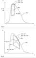
- the cavity pressure curve PGE intersects at least one process characteristic zone limit value EO', EO ", EO′′′ of the process characteristic variable zone EO. It is monitored whether the cavity pressure curve PGE intersects the first process characteristic zone limit value EO'. If the cavity pressure curve PGE intersects the first process characteristic variable zone limit value EO ' cuts, monitoring information is output that the production cycle produces good parts Fig. 10 the cavity pressure curve PGE intersects the first process parameter zone limit value EO ⁇ , so that monitoring information is output that the production cycle produces good parts. After Fig. 11 the cavity pressure curve PGE does not intersect the first process parameter zone limit value EO', so that monitoring information is output that the production cycle does not produce any good parts.
- a recorded process parameter variant that is largest in terms of the dimension time t is used as the third process parameter limit value EO′′′ of the process parameter zone. It is monitored whether the cavity pressure curve PGE intersects the third process parameter zone limit value EO′′′. If the cavity pressure curve PGE intersects the third process parameter zone limit EO′′′, monitoring information is output that the production cycle produces good parts. After 10 and 11 the cavity pressure curve PGE intersects the third process parameter zone limit EO′′′, so that monitoring information is output that the production cycle produces good parts.
- the person skilled in the art can combine the various alternatives for monitoring the determined process parameter and/or the cavity pressure curve with the process parameter zone. In this way, it can be monitored whether the tool cavity pressure curve PGE intersects the first process parameter zone limit value EO' and the third process parameter zone limit value EO′′′. If the cavity pressure curve PGE intersects the two process parameter zone limit values EO', EO′′′, monitoring information is output that the production cycle produces good parts. After Fig. 10 the cavity pressure curve PGE intersects the two process parameter zone limit values EO', EO', so that monitoring information is output that the production cycle produces good parts. After Fig. 11 the cavity pressure curve PGE does not intersect the two process parameter zone limit values EO', EO', so that monitoring information is output that the production cycle does not produce any good parts.
- the embodiments of the process parameter zone EO are coordinated with the type of quality feature of the injection molded components produced and the type of quality tolerance of the injection molded components produced.
- the embodiments of the process parameter zone EO can also be combined with one another.
- a molded part is formed in the phases of filling a cavity with a melt, compressing the melt and solidifying the molded part. The first two phases take place before the cavity pressure maximum, the third phase takes place afterwards.
- a polygonal process parameter zone EO with the maximum cavity pressure value is preferably used as a process parameter.
- a polygonal process parameter zone EO with the cavity pressure gradient as a process parameter is preferably used ( Fig. 11 ).
- a polygonal process parameter zone EO with the maximum cavity pressure value is preferably used as a process parameter ( Fig. 10 ) and/or it becomes a polygonal process parameter zone EO with the cavity pressure gradient is used as a process parameter ( Fig. 11 ).
- a determined process parameter KE can also be added to the process parameter zone EO in a production cycle of the ongoing production process. For this to happen, the determined process parameter KE must be process-stable and the determined process parameter KE must be correlated with a process setting variable with which good parts are produced in the production process. With such a determined process parameter KE added to the process parameter zone EO, process parameter zone limit values EO', EO", EO′′′ of the process parameter zone EO can be adjusted and shifted with respect to a dimension such as the pressure P.
Landscapes
- Engineering & Computer Science (AREA)
- Manufacturing & Machinery (AREA)
- Mechanical Engineering (AREA)
- General Engineering & Computer Science (AREA)
- Quality & Reliability (AREA)
- Physics & Mathematics (AREA)
- General Physics & Mathematics (AREA)
- Automation & Control Theory (AREA)
- Injection Moulding Of Plastics Or The Like (AREA)
- General Factory Administration (AREA)
Claims (14)
- Procédé pour exécuter un processus cyclique de production, processus de production qui conduit à la production des articles ; dans lequel ledit processus de production est réglé par au moins une valeur de réglage du processus ; et dans lequel au moins une caractéristique de qualité des articles produits et au moins une plage de tolérance de qualité des articles produits sont prédéfinies ;a) dans lequel au moins une valeur de réglage du processus est variée de manière automatisée;b) dans lequel pour une valeur de réglage du processus variée au moins une variante d'une valeur caractéristique du processus (KE', KE", KE‴) est déterminée de manière automatisée ;c) dans lequel on vérifie de manière automatisée si la variante d'une valeur caractéristique du processus (KE', KE", KE‴) déterminée se situe dans une limite de stabilité (SG) du processus et si elle est stable dans le processus ;dans lequel, si une décision décide qu'il n'existe pas de stabilité du processus, l'étape du processus a) est répétée dans le cycle de production suivant avec une valeur de réglage du processus variée jusqu'à ce qu'une stabilité du processus soit atteinte;d) dans lequel on contrôle si la caractéristique de qualité des articles produits en utilisant une valeur de réglage du processus variée se situe dans la plage de tolérance de qualité pour les articles produits et si, par conséquent, des pièces bonnes ont été produites ; ete) dans lequel on établie de manière automatisée, en utilisant au moins une variante d'une valeur caractéristique du processus (KE', KE", KE‴) déterminée qui est stable dans le processus et dont la valeur de réglage du processus conduit à la production de pièces bonnes, une zone de valeur caractéristique du processus (EO),dans lequel ladite zone de valeur caractéristique du processus (EO) est un masque de contrôle pour un cycle de production du processus de production en cours dans lequel au moins une valeur caractéristique du processus (KE) est déterminée à partir de données de capteur,dans lequel on surveille si la valeur caractéristique du processus (KE) déterminée se situe dans la zone de valeur caractéristique du processus (EO) est dans lequel, si la valeur caractéristique du processus (KE) déterminée se situe dans la zone de valeur caractéristique du processus (EO), une information de surveillance est donnée indiquant que le cycle de production produit des pièces bonnes.
- Procédé selon la revendication 1, caractérisé en ce qu'une première valeur limite de la zone de valeur caractéristique du processus (EO`) de la zone de valeur caractéristique du processus (EO) est déterminée en utilisant une variante d'une valeur caractéristique du processus (KE', KE") qui est la plus petite par rapport à une dimension d'une valeur caractéristique du processus ; et/ou en ce qu'une deuxième valeur limite de la zone de valeur caractéristique du processus (EO") de la zone de valeur caractéristique du processus (EO) est déterminée en utilisant une variante d'une valeur caractéristique du processus (KE', KE") qui est la plus grande par rapport à une dimension de la valeur caractéristique du processus.
- Procédé selon l'une quelconque des revendications 1 ou 2, caractérisé en ce qu'il existe, pour une valeur de réglage du processus variée, au moins une variante d'une valeur caractéristique du processus (KS', KS") qui est stable dans le processus, où ladite variante d'une valeur caractéristique du processus (KS', KS") stable dans le processus est utilisée pour établir au moins une limite de stabilité (SG) du processus dans une procédure de sélection statistique.
- Procédé selon la revendication 3, caractérisé en ce qu'une valeur de réglage du processus est prédéterminée, ladite valeur de réglage du processus étant corrélée à au moins une valeur caractéristique du processus (K), ladite valeur caractéristique du processus (K) étant également prédéterminé, et en ce que ladite variante d'une valeur caractéristique du processus (KS', KS") stable dans le processus est déterminée à partir des données de capteur.
- Procédé selon la revendication 3, caractérisé en ce que ladite valeur caractéristique du processus (K) prédéterminé et ladite variante d'une valeur caractéristique du processus (KS', KS") stable dans le processus sont utilisées pour calculer une moyenne arithmétique (M) et un écart type (σP, σt) ; en ce que la moyenne arithmétique (M) est positionnée au centre d'un ellipsoïde ; et en ce qu'on détermine, en utilisant l'écart type (σP, σt), la longueur ou un multiple de la longueur des demi-axes de l'ellipsoïde ; et en ce que la limite de stabilité (SG) du processus est calculé en utilisant un périmètre de l'ellipsoïde.
- Procédé selon l'une quelconque des revendications 3 à 5, caractérisé en ce que la contrôle de la production de pièces bonnes n'est effectuée que pour les articles produits dont la valeur de réglage du processus variée est corrélée à une variante d'une valeur caractéristique du processus (KS', KS") qui est stable dans le processus.
- Procédé selon la revendication 6, caractérisé en ce que, si la valeur caractéristique du processus (KE) déterminée se situe localement dans la zone de valeur caractéristique du processus (EO), une information de surveillance est donnée indiquant que le cycle de production produit des pièces bonnes.
- Procédé selon la revendication 6, caractérisé en ce qu'une évolution de la valeur caractéristique du processus (KE) déterminée dans le temps est représentée graphiquement ; en ce que la représentation graphique de la valeur caractéristique du processus (KE) déterminée est superposée à la zone de valeur caractéristique du processus (EO) ; en ce que l'on surveille si ladite représentation graphique de la valeur caractéristique du processus (KE) déterminée se situe localement dans la zone de valeur caractéristique du processus (EO) ; et en ce que, si la représentation graphique de la valeur caractéristique du processus (KE) déterminée se situe localement dans la zone de valeur caractéristique du processus (EO), une information de surveillance est donnée informant que le cycle de production produit des pièces bonnes.
- Procédé selon la revendication 8, caractérisé en ce que pour un cycle de production du processus de production en cours, les pressions de cavité sont utilisées en tant que valeur caractéristique du processus (KE) ; en ce que l'évolution des pressions de cavité détectées dans le temps est représentée graphiquement sous la forme d'une courbe de pression de cavité (PGE) ; en ce que la courbe de pression de cavité (PGE) est superposée à la zone de valeur caractéristique du processus (EO) ; en ce que l'on surveille si la courbe de pression de cavité (PGE) se situe localement dans la zone de valeur caractéristique du processus (EO) ; et en ce que, si la courbe de pression de cavité (PGE) se situe localement dans la zone de valeur caractéristique du processus (EO, une information de surveillance est donnée indiquant que le cycle de production produit des pièces bonnes.
- Procédé selon l'une quelconque des revendications 7 à 9, caractérisé en ce que l'on surveille si la représentation graphique de la valeur caractéristique du processus (KE) déterminée coupe au moins une valeur limite de la zone de valeur caractéristique du processus (EO', EO", EO‴).
- Procédé selon l'une quelconque des revendications 1 à 10, caractérisé en ce que le processus de production est un processus de moulage par injection dans lequel une vitesse d'injection et/ou une pression de maintien est utilisée en tant que valeur de réglage du processus prédéterminée et dans lequel des pièces de moulage par injection sont produites en tant qu'articles.
- Procédé selon la revendication 11, caractérisé en ce qu'une valeur maximale de la pression de cavité (PM, PM', PM", PM‴, PME) et/ou une pente de la pression de cavité (PS, PS', PS", PS‴, PSE) est utilisée en tant que valeur caractéristique du processus.
- Procédé selon la revendication 11, caractérisé en ce que pour contrôler le remplissage complète de la cavité du moule (Short Shot) dans la production de pièces de moulage par injection on utilise une zone de valeur caractéristique du processus (EO) polygonale avec la valeur maximale de la pression de cavité (PM, PM', PM", PM‴, PME) en tant que valeur caractéristique du processus.
- Procédé selon la revendication 11, caractérisé en ce que pour contrôler la précision dimensionnelle des pièces de moulage par injection produites et/ou la taille des pièces de moulage par injection produites et/ou la formation de bavures sur les pièces de moulage par injection produites, on utilise une zone de valeur caractéristique du processus (EO) polygonale avec la valeur maximale de la pression de cavité (PM, PM', PM", PM‴, PME) en tant que valeur caractéristique du processus ou avec la pente de la pression de cavité (PS, PS', PS'', PS''', PSE) en tant que valeur caractéristique du processus.
Applications Claiming Priority (2)
| Application Number | Priority Date | Filing Date | Title |
|---|---|---|---|
| EP16156730 | 2016-02-22 | ||
| PCT/EP2017/053510 WO2017144344A1 (fr) | 2016-02-22 | 2017-02-16 | Procédé de mise en oeuvre d'un processus de production cyclique |
Publications (3)
| Publication Number | Publication Date |
|---|---|
| EP3420424A1 EP3420424A1 (fr) | 2019-01-02 |
| EP3420424C0 EP3420424C0 (fr) | 2024-04-03 |
| EP3420424B1 true EP3420424B1 (fr) | 2024-04-03 |
Family
ID=55409780
Family Applications (1)
| Application Number | Title | Priority Date | Filing Date |
|---|---|---|---|
| EP17707494.5A Active EP3420424B1 (fr) | 2016-02-22 | 2017-02-16 | Procede d'execution d'un procede de production cyclique |
Country Status (7)
| Country | Link |
|---|---|
| US (1) | US10960591B2 (fr) |
| EP (1) | EP3420424B1 (fr) |
| JP (1) | JP6714092B2 (fr) |
| CN (1) | CN108700870B (fr) |
| ES (1) | ES2985737T3 (fr) |
| PL (1) | PL3420424T3 (fr) |
| WO (1) | WO2017144344A1 (fr) |
Families Citing this family (10)
| Publication number | Priority date | Publication date | Assignee | Title |
|---|---|---|---|---|
| MX2021002784A (es) * | 2018-09-13 | 2021-03-25 | Imflux Inc | Metodos para controlar procesos de moldeo por inyeccion con base en la presion de fusion de plastico real o la presion de cavidad. |
| AT521726A1 (de) * | 2018-10-03 | 2020-04-15 | Engel Austria Gmbh | Verfahren zum Bestimmen eines physikalischen Zusammenhangs |
| US11373457B2 (en) * | 2018-11-06 | 2022-06-28 | Zf Friedrichshafen Ag | System and method for detecting non-approved parts in a vehicle |
| DE102019127988A1 (de) | 2019-10-16 | 2021-04-22 | Günther Heisskanaltechnik Gmbh | Verfahren zum Betrieb einer Nadelverschlussdüse |
| US12036712B2 (en) * | 2020-06-05 | 2024-07-16 | Jtekt Corporation | Molding conditions determination assist device and resin state estimation device |
| JP2023530121A (ja) * | 2020-06-15 | 2023-07-13 | アイエムフラックス インコーポレイテッド | 最大空隅矩形ベースのプロセス開発 |
| PL4351860T3 (pl) | 2021-06-09 | 2025-11-12 | Kistler Holding Ag | Sposób określania anomalii w cyklicznym procesie produkcyjnym |
| JP7576007B2 (ja) * | 2021-07-27 | 2024-10-30 | 株式会社日本製鋼所 | データセット作成方法、学習モデル生成方法、コンピュータプログラム及びデータセット作成装置 |
| JP7546532B2 (ja) * | 2021-08-31 | 2024-09-06 | 株式会社日本製鋼所 | 成形条件パラメータ調整方法、コンピュータプログラム、成形条件パラメータ調整装置及び成形機 |
| DE102021127549A1 (de) * | 2021-10-22 | 2023-04-27 | Bayerische Motoren Werke Aktiengesellschaft | Verfahren zum Überwachen einer Fertigungslinie zum Herstellen von Bauteilen, insbesondere für Kraftfahrzeuge |
Family Cites Families (9)
| Publication number | Priority date | Publication date | Assignee | Title |
|---|---|---|---|---|
| AT390753B (de) * | 1988-04-11 | 1990-06-25 | Boehler Gmbh | Fuehrung von flaechenmaterial in anlagen mit rundmessern |
| JPH08281756A (ja) | 1995-04-18 | 1996-10-29 | Ube Ind Ltd | 射出成形機の運転制御方法 |
| DE19801881C1 (de) | 1998-01-20 | 1999-05-27 | Karl Hehl | Verfahren zur Beurteilung von Spritzteilen |
| JP3981911B2 (ja) | 2001-11-09 | 2007-09-26 | 有限会社 ソフトロックス | 製造工程監視方法 |
| DE102010002174A1 (de) | 2010-02-22 | 2011-08-25 | Robert Bosch GmbH, 70469 | Verfahren zur Regelung eines Spritzgießprozesses |
| CN102486199A (zh) * | 2010-12-31 | 2012-06-06 | 上汽通用五菱汽车股份有限公司 | 一种发动机连杆的加工工艺 |
| CN103071978B (zh) * | 2013-01-10 | 2015-01-28 | 太仓久信精密模具有限公司 | 一种发电机爪极温冷联合成形工艺 |
| CN103116306B (zh) * | 2013-02-05 | 2015-06-17 | 浙江大学 | 一种自动的步进式有序时段划分方法 |
| CN104008248B (zh) * | 2014-06-04 | 2017-10-10 | 广西大学 | 基于高斯过程的注塑成形工艺稳健设计与容差设计方法 |
-
2017
- 2017-02-16 US US16/075,825 patent/US10960591B2/en active Active
- 2017-02-16 WO PCT/EP2017/053510 patent/WO2017144344A1/fr not_active Ceased
- 2017-02-16 ES ES17707494T patent/ES2985737T3/es active Active
- 2017-02-16 CN CN201780012662.2A patent/CN108700870B/zh active Active
- 2017-02-16 PL PL17707494.5T patent/PL3420424T3/pl unknown
- 2017-02-16 EP EP17707494.5A patent/EP3420424B1/fr active Active
- 2017-02-16 JP JP2018544091A patent/JP6714092B2/ja active Active
Also Published As
| Publication number | Publication date |
|---|---|
| PL3420424T3 (pl) | 2024-06-10 |
| EP3420424C0 (fr) | 2024-04-03 |
| WO2017144344A1 (fr) | 2017-08-31 |
| CN108700870B (zh) | 2021-09-03 |
| US20190039274A1 (en) | 2019-02-07 |
| US10960591B2 (en) | 2021-03-30 |
| CN108700870A (zh) | 2018-10-23 |
| JP6714092B2 (ja) | 2020-06-24 |
| ES2985737T3 (es) | 2024-11-07 |
| EP3420424A1 (fr) | 2019-01-02 |
| JP2019507035A (ja) | 2019-03-14 |
Similar Documents
| Publication | Publication Date | Title |
|---|---|---|
| EP3420424A1 (fr) | Procédé de mise en oeuvre d'un processus de production cyclique | |
| DE102018106808B4 (de) | Zustandsbestimmungsvorrichtung | |
| DE112013003388B4 (de) | Kollisionsprüfvorrichtung und Numeriksteuervorrichtung | |
| WO2018072773A2 (fr) | Procédé de surveillance d'un processus de production, procédé de déduction indirecte d'une dépendance systématique, procédé d'adaptation de la qualité, procédé de démarrage d'un processus de production, procédé de fabrication d'un produit d'extrusion et installation de fabrication d'un produit d'extrusion | |
| DE19743600B4 (de) | Verfahren zur Überwachung eines zyklischen Produktionsprozesses | |
| EP3671373A1 (fr) | Méthode de prédiction pour prédire le résultat de l'usinage pour une méthode d'usinage à laser | |
| DE112017001244T5 (de) | Analysemethode für Herstellungsprozesse | |
| EP2824450B1 (fr) | Utilisation d'un procede d'evaluation d'un resultat d'une analyse thermique, produit de programme informatique et combinaison d'une installation de production ou de traitement et systeme pour la realisation de l'utilisation | |
| DE69006846T2 (de) | Verfahren zum unterscheiden nichtdefekter teile von defekten teilen bei spritzgiessmaschinen. | |
| DE102020102406A1 (de) | Managementvorrichtung und managementsystem | |
| EP3038818A1 (fr) | Procédé et dispositif de production d'un matériau de départ pour pneus de véhicules | |
| EP3961166A1 (fr) | Procédé d'impression d'un décor et dispositif correspondant | |
| DE102016106522A1 (de) | Vorrichtung für mindestens einen industriellen automatisierten Prozess | |
| WO2019233735A1 (fr) | Procédé de garantie de la qualité lors de la production d'un produit, dispositif de calcul et programme d'ordinateur | |
| EP0784535B1 (fr) | Procede concu pour influer sur des valeurs de consigne de machines, et dispositif de mise en oeuvre dudit procede | |
| DE19952834A1 (de) | Verfahren zum Überwachen eines Pressenbetriebes | |
| EP3525049A1 (fr) | Détermination de données d'état d'un système de production | |
| EP0698481B1 (fr) | Procédé de commande floue pour assurer la qualité dans la fabrication de comprimés | |
| DE4132002A1 (de) | Verfahren zur ermittlung unzulaessiger abweichungen von verfahrensparametern | |
| EP4327171B1 (fr) | Procédé de commande de processus sur des machines de traitement de matières plastiques | |
| WO2020094635A1 (fr) | Procédé et dispositif permettant de contrôler un profil d'épaisseur d'une feuille continue | |
| EP4075218A1 (fr) | Procédé, dispositif et système d'ajustement d'un processus de production | |
| DE102022127260A1 (de) | Prozesskennzahlermittlung | |
| EP4356209A1 (fr) | Surveillance de la production de panneaux de matériau, en particulier de panneaux en matériau dérivé du bois, en particulier à l'aide d'une carte auto-organisatrice | |
| EP3783448B1 (fr) | Procédé de tester d'un processus de production destiné à la fabrication de composants |
Legal Events
| Date | Code | Title | Description |
|---|---|---|---|
| STAA | Information on the status of an ep patent application or granted ep patent |
Free format text: STATUS: UNKNOWN |
|
| STAA | Information on the status of an ep patent application or granted ep patent |
Free format text: STATUS: THE INTERNATIONAL PUBLICATION HAS BEEN MADE |
|
| PUAI | Public reference made under article 153(3) epc to a published international application that has entered the european phase |
Free format text: ORIGINAL CODE: 0009012 |
|
| STAA | Information on the status of an ep patent application or granted ep patent |
Free format text: STATUS: REQUEST FOR EXAMINATION WAS MADE |
|
| 17P | Request for examination filed |
Effective date: 20180808 |
|
| AK | Designated contracting states |
Kind code of ref document: A1 Designated state(s): AL AT BE BG CH CY CZ DE DK EE ES FI FR GB GR HR HU IE IS IT LI LT LU LV MC MK MT NL NO PL PT RO RS SE SI SK SM TR |
|
| AX | Request for extension of the european patent |
Extension state: BA ME |
|
| DAV | Request for validation of the european patent (deleted) | ||
| DAX | Request for extension of the european patent (deleted) | ||
| STAA | Information on the status of an ep patent application or granted ep patent |
Free format text: STATUS: EXAMINATION IS IN PROGRESS |
|
| 17Q | First examination report despatched |
Effective date: 20200416 |
|
| GRAP | Despatch of communication of intention to grant a patent |
Free format text: ORIGINAL CODE: EPIDOSNIGR1 |
|
| STAA | Information on the status of an ep patent application or granted ep patent |
Free format text: STATUS: GRANT OF PATENT IS INTENDED |
|
| INTG | Intention to grant announced |
Effective date: 20231120 |
|
| GRAS | Grant fee paid |
Free format text: ORIGINAL CODE: EPIDOSNIGR3 |
|
| GRAA | (expected) grant |
Free format text: ORIGINAL CODE: 0009210 |
|
| STAA | Information on the status of an ep patent application or granted ep patent |
Free format text: STATUS: THE PATENT HAS BEEN GRANTED |
|
| AK | Designated contracting states |
Kind code of ref document: B1 Designated state(s): AL AT BE BG CH CY CZ DE DK EE ES FI FR GB GR HR HU IE IS IT LI LT LU LV MC MK MT NL NO PL PT RO RS SE SI SK SM TR |
|
| REG | Reference to a national code |
Ref country code: GB Ref legal event code: FG4D Free format text: NOT ENGLISH |
|
| REG | Reference to a national code |
Ref country code: CH Ref legal event code: EP |
|
| REG | Reference to a national code |
Ref country code: IE Ref legal event code: FG4D Free format text: LANGUAGE OF EP DOCUMENT: GERMAN |
|
| REG | Reference to a national code |
Ref country code: DE Ref legal event code: R096 Ref document number: 502017015986 Country of ref document: DE |
|
| U01 | Request for unitary effect filed |
Effective date: 20240403 |
|
| U07 | Unitary effect registered |
Designated state(s): AT BE BG DE DK EE FI FR IT LT LU LV MT NL PT SE SI Effective date: 20240409 |
|
| PG25 | Lapsed in a contracting state [announced via postgrant information from national office to epo] |
Ref country code: IS Free format text: LAPSE BECAUSE OF FAILURE TO SUBMIT A TRANSLATION OF THE DESCRIPTION OR TO PAY THE FEE WITHIN THE PRESCRIBED TIME-LIMIT Effective date: 20240803 |
|
| PG25 | Lapsed in a contracting state [announced via postgrant information from national office to epo] |
Ref country code: HR Free format text: LAPSE BECAUSE OF FAILURE TO SUBMIT A TRANSLATION OF THE DESCRIPTION OR TO PAY THE FEE WITHIN THE PRESCRIBED TIME-LIMIT Effective date: 20240403 |
|
| PG25 | Lapsed in a contracting state [announced via postgrant information from national office to epo] |
Ref country code: GR Free format text: LAPSE BECAUSE OF FAILURE TO SUBMIT A TRANSLATION OF THE DESCRIPTION OR TO PAY THE FEE WITHIN THE PRESCRIBED TIME-LIMIT Effective date: 20240704 |
|
| PG25 | Lapsed in a contracting state [announced via postgrant information from national office to epo] |
Ref country code: NO Free format text: LAPSE BECAUSE OF FAILURE TO SUBMIT A TRANSLATION OF THE DESCRIPTION OR TO PAY THE FEE WITHIN THE PRESCRIBED TIME-LIMIT Effective date: 20240703 Ref country code: IS Free format text: LAPSE BECAUSE OF FAILURE TO SUBMIT A TRANSLATION OF THE DESCRIPTION OR TO PAY THE FEE WITHIN THE PRESCRIBED TIME-LIMIT Effective date: 20240803 Ref country code: HR Free format text: LAPSE BECAUSE OF FAILURE TO SUBMIT A TRANSLATION OF THE DESCRIPTION OR TO PAY THE FEE WITHIN THE PRESCRIBED TIME-LIMIT Effective date: 20240403 Ref country code: GR Free format text: LAPSE BECAUSE OF FAILURE TO SUBMIT A TRANSLATION OF THE DESCRIPTION OR TO PAY THE FEE WITHIN THE PRESCRIBED TIME-LIMIT Effective date: 20240704 Ref country code: RS Free format text: LAPSE BECAUSE OF FAILURE TO SUBMIT A TRANSLATION OF THE DESCRIPTION OR TO PAY THE FEE WITHIN THE PRESCRIBED TIME-LIMIT Effective date: 20240703 |
|
| REG | Reference to a national code |
Ref country code: ES Ref legal event code: FG2A Ref document number: 2985737 Country of ref document: ES Kind code of ref document: T3 Effective date: 20241107 |
|
| REG | Reference to a national code |
Ref country code: DE Ref legal event code: R097 Ref document number: 502017015986 Country of ref document: DE |
|
| PG25 | Lapsed in a contracting state [announced via postgrant information from national office to epo] |
Ref country code: SK Free format text: LAPSE BECAUSE OF FAILURE TO SUBMIT A TRANSLATION OF THE DESCRIPTION OR TO PAY THE FEE WITHIN THE PRESCRIBED TIME-LIMIT Effective date: 20240403 Ref country code: RO Free format text: LAPSE BECAUSE OF FAILURE TO SUBMIT A TRANSLATION OF THE DESCRIPTION OR TO PAY THE FEE WITHIN THE PRESCRIBED TIME-LIMIT Effective date: 20240403 |
|
| PG25 | Lapsed in a contracting state [announced via postgrant information from national office to epo] |
Ref country code: SM Free format text: LAPSE BECAUSE OF FAILURE TO SUBMIT A TRANSLATION OF THE DESCRIPTION OR TO PAY THE FEE WITHIN THE PRESCRIBED TIME-LIMIT Effective date: 20240403 |
|
| PG25 | Lapsed in a contracting state [announced via postgrant information from national office to epo] |
Ref country code: SM Free format text: LAPSE BECAUSE OF FAILURE TO SUBMIT A TRANSLATION OF THE DESCRIPTION OR TO PAY THE FEE WITHIN THE PRESCRIBED TIME-LIMIT Effective date: 20240403 Ref country code: SK Free format text: LAPSE BECAUSE OF FAILURE TO SUBMIT A TRANSLATION OF THE DESCRIPTION OR TO PAY THE FEE WITHIN THE PRESCRIBED TIME-LIMIT Effective date: 20240403 Ref country code: RO Free format text: LAPSE BECAUSE OF FAILURE TO SUBMIT A TRANSLATION OF THE DESCRIPTION OR TO PAY THE FEE WITHIN THE PRESCRIBED TIME-LIMIT Effective date: 20240403 |
|
| PLBE | No opposition filed within time limit |
Free format text: ORIGINAL CODE: 0009261 |
|
| STAA | Information on the status of an ep patent application or granted ep patent |
Free format text: STATUS: NO OPPOSITION FILED WITHIN TIME LIMIT |
|
| 26N | No opposition filed |
Effective date: 20250106 |
|
| U20 | Renewal fee for the european patent with unitary effect paid |
Year of fee payment: 9 Effective date: 20250221 |
|
| PGFP | Annual fee paid to national office [announced via postgrant information from national office to epo] |
Ref country code: ES Payment date: 20250331 Year of fee payment: 9 |
|
| PGFP | Annual fee paid to national office [announced via postgrant information from national office to epo] |
Ref country code: CH Payment date: 20250411 Year of fee payment: 9 |
|
| PG25 | Lapsed in a contracting state [announced via postgrant information from national office to epo] |
Ref country code: MC Free format text: LAPSE BECAUSE OF FAILURE TO SUBMIT A TRANSLATION OF THE DESCRIPTION OR TO PAY THE FEE WITHIN THE PRESCRIBED TIME-LIMIT Effective date: 20240403 |
|
| PG25 | Lapsed in a contracting state [announced via postgrant information from national office to epo] |
Ref country code: IE Free format text: LAPSE BECAUSE OF NON-PAYMENT OF DUE FEES Effective date: 20250216 |
|
| U20 | Renewal fee for the european patent with unitary effect paid |
Year of fee payment: 10 Effective date: 20260225 |
|
| PGFP | Annual fee paid to national office [announced via postgrant information from national office to epo] |
Ref country code: GB Payment date: 20260219 Year of fee payment: 10 |
|
| REG | Reference to a national code |
Ref country code: CH Ref legal event code: U11 Free format text: ST27 STATUS EVENT CODE: U-0-0-U10-U11 (AS PROVIDED BY THE NATIONAL OFFICE) Effective date: 20260422 |
|
| PGFP | Annual fee paid to national office [announced via postgrant information from national office to epo] |
Ref country code: CZ Payment date: 20260212 Year of fee payment: 10 |
|
| PGFP | Annual fee paid to national office [announced via postgrant information from national office to epo] |
Ref country code: PL Payment date: 20260122 Year of fee payment: 10 |