EP3421169A1 - Schutzglas mit transponder und einbauhilfe sowie zugehöriges laserwerkzeug - Google Patents
Schutzglas mit transponder und einbauhilfe sowie zugehöriges laserwerkzeug Download PDFInfo
- Publication number
- EP3421169A1 EP3421169A1 EP18174069.7A EP18174069A EP3421169A1 EP 3421169 A1 EP3421169 A1 EP 3421169A1 EP 18174069 A EP18174069 A EP 18174069A EP 3421169 A1 EP3421169 A1 EP 3421169A1
- Authority
- EP
- European Patent Office
- Prior art keywords
- protective glass
- handle
- transponder
- protective
- cassette
- Prior art date
- Legal status (The legal status is an assumption and is not a legal conclusion. Google has not performed a legal analysis and makes no representation as to the accuracy of the status listed.)
- Granted
Links
Images

Classifications
-
- B—PERFORMING OPERATIONS; TRANSPORTING
- B23—MACHINE TOOLS; METAL-WORKING NOT OTHERWISE PROVIDED FOR
- B23K—SOLDERING OR UNSOLDERING; WELDING; CLADDING OR PLATING BY SOLDERING OR WELDING; CUTTING BY APPLYING HEAT LOCALLY, e.g. FLAME CUTTING; WORKING BY LASER BEAM
- B23K26/00—Working by laser beam, e.g. welding, cutting or boring
- B23K26/70—Auxiliary operations or equipment
- B23K26/702—Auxiliary equipment
- B23K26/706—Protective screens
-
- B—PERFORMING OPERATIONS; TRANSPORTING
- B23—MACHINE TOOLS; METAL-WORKING NOT OTHERWISE PROVIDED FOR
- B23K—SOLDERING OR UNSOLDERING; WELDING; CLADDING OR PLATING BY SOLDERING OR WELDING; CUTTING BY APPLYING HEAT LOCALLY, e.g. FLAME CUTTING; WORKING BY LASER BEAM
- B23K26/00—Working by laser beam, e.g. welding, cutting or boring
- B23K26/02—Positioning or observing the workpiece, e.g. with respect to the point of impact; Aligning, aiming or focusing the laser beam
- B23K26/03—Observing, e.g. monitoring, the workpiece
-
- B—PERFORMING OPERATIONS; TRANSPORTING
- B23—MACHINE TOOLS; METAL-WORKING NOT OTHERWISE PROVIDED FOR
- B23K—SOLDERING OR UNSOLDERING; WELDING; CLADDING OR PLATING BY SOLDERING OR WELDING; CUTTING BY APPLYING HEAT LOCALLY, e.g. FLAME CUTTING; WORKING BY LASER BEAM
- B23K26/00—Working by laser beam, e.g. welding, cutting or boring
- B23K26/02—Positioning or observing the workpiece, e.g. with respect to the point of impact; Aligning, aiming or focusing the laser beam
- B23K26/06—Shaping the laser beam, e.g. by masks or multi-focusing
- B23K26/064—Shaping the laser beam, e.g. by masks or multi-focusing by means of optical elements, e.g. lenses, mirrors or prisms
- B23K26/0648—Shaping the laser beam, e.g. by masks or multi-focusing by means of optical elements, e.g. lenses, mirrors or prisms comprising lenses
-
- B—PERFORMING OPERATIONS; TRANSPORTING
- B23—MACHINE TOOLS; METAL-WORKING NOT OTHERWISE PROVIDED FOR
- B23K—SOLDERING OR UNSOLDERING; WELDING; CLADDING OR PLATING BY SOLDERING OR WELDING; CUTTING BY APPLYING HEAT LOCALLY, e.g. FLAME CUTTING; WORKING BY LASER BEAM
- B23K26/00—Working by laser beam, e.g. welding, cutting or boring
- B23K26/14—Working by laser beam, e.g. welding, cutting or boring using a fluid stream, e.g. a jet of gas, in conjunction with the laser beam; Nozzles therefor
- B23K26/1462—Nozzles; Features related to nozzles
-
- B—PERFORMING OPERATIONS; TRANSPORTING
- B23—MACHINE TOOLS; METAL-WORKING NOT OTHERWISE PROVIDED FOR
- B23K—SOLDERING OR UNSOLDERING; WELDING; CLADDING OR PLATING BY SOLDERING OR WELDING; CUTTING BY APPLYING HEAT LOCALLY, e.g. FLAME CUTTING; WORKING BY LASER BEAM
- B23K26/00—Working by laser beam, e.g. welding, cutting or boring
- B23K26/70—Auxiliary operations or equipment
- B23K26/702—Auxiliary equipment
-
- G—PHYSICS
- G06—COMPUTING OR CALCULATING; COUNTING
- G06K—GRAPHICAL DATA READING; PRESENTATION OF DATA; RECORD CARRIERS; HANDLING RECORD CARRIERS
- G06K7/00—Methods or arrangements for sensing record carriers, e.g. for reading patterns
- G06K7/10—Methods or arrangements for sensing record carriers, e.g. for reading patterns by electromagnetic radiation, e.g. optical sensing; by corpuscular radiation
- G06K7/10009—Methods or arrangements for sensing record carriers, e.g. for reading patterns by electromagnetic radiation, e.g. optical sensing; by corpuscular radiation sensing by radiation using wavelengths larger than 0.1 mm, e.g. radio-waves or microwaves
Definitions
- the invention relates to a protective glass intended for installation in a laser tool of a laser processing machine with a transponder, in particular an RFID transponder, in which data relating to the protective glass can be stored in a contactless readable manner and / or can be stored without contact.
- Such a protective glass is for example by the DE 10 2011 078 359 A1 known.
- Laser tools (laser processing head) of laser processing machines usually have a focusing optics for focusing the directed onto a workpiece Laser beam and one of the focusing optics upstream protective glass to protect the focusing optics from contamination by the particles and vapors occurring during workpiece processing.
- the protective glass When mounting in the laser tool, the protective glass must be picked up with your fingers and placed in a protective glass holder of the laser tool, without causing fingerprints on the protective glass.
- a transponder on an optical element of the laser processing machine, in which data relating to the optical element, that is to say for example with respect to the history and the soiling state, are stored.
- the transponder for example an RFID tag, is mounted on a surface of the optical element which is not used optically or is not detected by the laser beam during operation of a laser processing machine and can be written and read without mechanical contacting.
- a protective glass for example, the permissible wavelength range, the current degree of soiling, the duration of use and a number of other parameters of the protective glass can be stored in the transponder and thus assigned directly to the respective protective glass.
- the present invention has the object, a protective glass of the type mentioned in such a way that when installed in a laser tool as possible no dirt on the protective glass can occur more, as well as specify an associated laser tool.
- the protective glass with its transponder is oriented correctly to the read / write unit of the laser tool.
- a handle supporting the transponder as installation aid in particular glued.
- the handle is from the protective glass, in particular from its peripheral surface or glass edge, radially outward.
- the handle serves both as an installation aid, which makes a direct touch of the protective glass superfluous, as well as a carrier for the transponder.
- the protective glass can be installed without touching the glass, and thus free of fingerprints.
- the transponder attached to the handle has a higher optical quality than an RFID label merely glued to the protective glass.
- the transponder can be fastened to the outside on one of the two sides of the handle or can be enclosed or grasped in the handle. In the latter case, the handle then forms at the same time the housing of the transponder, which is additionally protected by the housing.
- the handle has a coding, in particular a mechanical or optical coding, as an orientation aid for the correct installation of the protective glass and thus for the correct orientation of the transponder to a read / write device of the laser tool.
- the coding prevents twisted installation of the protective glass. This would be the case if the possibly already dirty side of the protective glass would point in the direction of the focusing optics. The dirt particles would thus be able to reach the focusing optics unhindered and damage them.
- a mechanical coding can be particularly easily formed by an asymmetric outer contour of the handle, in particular by a beveled corner of the handle, or by a non-eccentric in the thickness direction of the protective glass attachment of the handle on the peripheral surface of the protective glass.
- an optical coding can be realized by a marking applied only on one of the two sides of the handle, which marks the correct position of the mounting side.
- the handle is dimensioned so that an operator can only grasp it with his thumb and forefinger. For this it is sufficient if the width of the handle in the circumferential direction of the protective glass is at least 5mm and at most 30mm.
- the handle is a socket formed of the protective glass, which surrounds the peripheral surface of the protective glass and may advantageously be formed by a plastic injection molded part, in which both the protective glass and the transponder are integrated or embedded respectively as inserts. In this case, the transponder is completely protected by the socket.
- the invention also relates to a protective glass cassette with a receiving opening and with a protective glass formed as above, which is inserted into the receiving opening, wherein the receiving opening has an edge recess for the handle attached to the protective glass.
- the edge recess has an asymmetrical contour corresponding to an asymmetrical outer contour of the handle, in particular a beveled corner, so as to ensure the correct installation of the protective glass in the receiving opening.
- the invention further relates to a laser tool of a laser processing machine having at least one protective glass cassette constructed in the beam path of a laser beam and having at least one reading and / or writing device for non-contact data exchange with the transponder of the protective glass of the at least one built-in protective glass cassette.
- the protective glass or protective glass cassette is usually arranged at the workpiece-facing end of the laser tool in order to protect a focusing optics from the particles and vapors occurring during workpiece machining.
- the laser tool preferably has a scattered light measuring device for monitoring the protective glass of the at least one built-in protective glass cassette for contamination.
- the protective glasses of the at least two built-in protective glass cassettes are each a reading and / or writing device or a single, common reading and / or writing device for Contactless data exchange with the transponders of the protective glasses and a common scattered light measuring device for monitoring the protective glasses assigned to contamination.
- FIG. 1 shown round protective glass 1 is for installation in a laser tool 10 ( Fig. 2 ) of a laser processing machine and has an RFID transponder 2 , are stored in the data relative to the protective glass 1 read-without readable and / or stored without contact.
- a handle 4 carrying the transponder 2 is attached as an installation aid, in particular adhered laterally.
- This handle 4 is dimensioned so that an operator can hold it between the thumb and forefinger, and can be performed by a protruding from the peripheral surface 3 radially outward flag whose width in the circumferential direction of the protective glass is 1 to about 10mm.
- the transponder 2 may be attached externally on one of the two sides of the handle 4 or housed or grasped in the handle 4. In the latter case, the handle then forms the housing of the transponder 2 at the same time.
- the handle 4 is not arranged on the circumferential surface 3 in the middle in the thickness direction of the protective glass 1, but to the in Fig. 1 upper guard glass side closer than the lower guard glass side.
- This eccentric arrangement in the thickness direction of the handle 4 represents a mechanical coding 5 as an orientation aid for the correct installation of the protective glass 1.
- the handle 4 may also be provided with an optical marking of the mounting side.
- the handle 4 is formed as an annular socket 6 , which surrounds the peripheral surface 3 of the protective glass 1 and is formed by a plastic injection molded part, in which both the protective glass 1 and the transponder 2 are integrated as inserts.
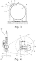
- Fig. 3 shows a protective glass cassette 6 with an upwardly open, round receiving opening 7, in which a protective glass 1 with a opposite Fig. 1 modified mechanical coding 5 is inserted from above by means of the handle 4.
- the receiving opening 7 has an edge recess 8 .
- the mechanical coding 5 is formed by an asymmetrical contour of the handle 4, here by a beveled corner of the handle 4, which cooperates with a correspondingly asymmetrical contour of the edge recess 8, here with a bevelled corner 9 of the edge recess 8.
- laser tool (laser processing head) 10 transports and focuses a laser beam 11, which via a glass fiber from a laser source comes, by means not shown here, focusing optics onto a workpiece 12.
- the laser tool 10 at its workpiece end facing two in the beam path of the laser beam 11 one above the other built-in protective glass cartridge 6, each having a Protective glass 1 on.
- the protective glass cassettes 6 with their inserted protective glasses 1 are inserted into cassette compartments of the laser tool 10 (not shown here).
- a reading and / or writing device 14 for contactless data exchange with the transponders 2 of the two built-in protective glasses 1 and a scattered light measuring device 15 for monitoring the two built-in protective glasses 1 are housed.
- the data stored in the transponders 2 can be read out and data (eg the current degree of soiling of the protective glasses 1) can be written back into the respective transponder 2.
- data eg the current degree of soiling of the protective glasses 1
Landscapes
- Engineering & Computer Science (AREA)
- Physics & Mathematics (AREA)
- Optics & Photonics (AREA)
- Plasma & Fusion (AREA)
- Mechanical Engineering (AREA)
- Toxicology (AREA)
- Health & Medical Sciences (AREA)
- Electromagnetism (AREA)
- General Health & Medical Sciences (AREA)
- Artificial Intelligence (AREA)
- Computer Vision & Pattern Recognition (AREA)
- General Physics & Mathematics (AREA)
- Theoretical Computer Science (AREA)
- Laser Beam Processing (AREA)
Abstract
Description
- Die Erfindung betrifft ein zum Einbau in ein Laserwerkzeug einer Laserbearbeitungsmaschine bestimmtes Schutzglas mit einem Transponder, insbesondere RFID-Transponder, in dem Daten bezüglich des Schutzglases berührungslos auslesbar gespeichert und/oder berührungslos speicherbar sind.
- Ein derartiges Schutzglas ist beispielsweise durch die
DE 10 2011 078 359 A1 bekannt geworden. - Laserwerkzeuge (Laserbearbeitungskopf) von Laserbearbeitungsmaschinen weisen meist eine Fokussieroptik zum Fokussieren des auf ein Werkstück gerichteten Laserstrahls und ein der Fokussieroptik vorgeordnetes Schutzglas auf, um die Fokussieroptik vor Verschmutzung durch die bei der Werkstückbearbeitung auftretenden Partikel und Dämpfe zu schützen. Beim Einbau in das Laserwerkzeug muss das Schutzglas mit den Fingern aufgenommen und in einen Schutzglashalter des Laserwerkzeugs gelegt werden, ohne dabei das Schutzglas durch Fingerabdrücke zu verschmutzen.
- Aus der
DE 10 2011 078 359 A1 ist es bekannt, an einem optischen Element der Laserbearbeitungsmaschine einen Transponder anzuordnen, in dem Daten bezüglich des optischen Elements, also beispielsweise bzgl. der Historie und des Verschmutzungszustands, gespeichert sind. Der Transponder, z.B. ein RFID-Etikett, wird auf einer im Betrieb einer Laserbearbeitungsmaschine optisch ungenutzten oder vom Laserstrahl nicht erfassten Fläche des optischen Elements angebracht und kann ohne mechanische Kontaktierung beschrieben und gelesen werden. Im Fall eines Schutzglases können im Transponder beispielsweise der zulässige Wellenlängenbereich, der aktuelle Verschmutzungsgrad, die Einsatzdauer und eine Reihe anderer Parameter des Schutzglases gespeichert und somit direkt dem jeweiligen Schutzglas zugeordnet sein. - Demgegenüber liegt der vorliegenden Erfindung die Aufgabe zugrunde, ein Schutzglas der eingangs genannten Art dahingehend weiterzubilden, dass beim Einbau in ein Laserwerkzeug möglichst keine Verschmutzungen auf dem Schutzglas mehr auftreten können, sowie ein zugehöriges Laserwerkzeug anzugeben. Insbesondere soll auch sichergestellt werden, dass beim Einbau in das Laserwerkzeug das Schutzglas mit seinem Transponder korrekt zur Schreib-/Leseeinheit des Laserwerkzeugs orientiert ist.
- Diese Aufgabe wird erfindungsgemäß dadurch gelöst, dass unmittelbar am Schutzglas, insbesondere an dessen Umfangsfläche, eine den Transponder tragende Handhabe als Einbauhilfe befestigt, insbesondere angeklebt ist. Vorzugsweise steht die Handhabe vom Schutzglas, insbesondere von dessen Umfangsfläche bzw. Glasrand, radial nach außen ab.
- Erfindungsgemäß dient die Handhabe sowohl als Einbauhilfe, die ein direktes Anfassen des Schutzglases überflüssig macht, als auch als Träger für den Transponder. Durch die Handhabe kann das Schutzglas ohne Berühren des Glases, und somit frei von Fingerabdrücken, eingebaut werden. Außerdem ist der an der Handhabe angebrachte Transponder optisch hochwertiger als ein auf das Schutzglas lediglich aufgeklebtes RFID-Etikett.
- Der Transponder kann außen auf einer der beiden Seiten der Handhabe befestigt oder aber in der Handhabe eingehaust bzw. gefasst sein. Im letzteren Fall bildet die Handhabe dann gleichzeitig das Gehäuse des Transponders, der durch das Gehäuse zusätzlich geschützt ist.
- Bevorzugt weist die Handhabe eine Kodierung, insbesondere eine mechanische oder optische Kodierung, als Orientierungshilfe für den lagerichtigen Einbau des Schutzglases und somit für die richtige Ausrichtung des Transponders zu einer Schreib-/Leseeinrichtung des Laserwerkzeugs auf. Neben der korrekten Ausrichtung des Transponders zur Schreib-/Leseeinrichtung verhindert die Kodierung ein verdrehtes Einbauen des Schutzglases. Dies wäre dann der Fall, wenn die evtl. bereits verschmutzte Seite des Schutzglases in Richtung Fokussieroptik zeigen würde. Die Schmutzpartikel würden so ungehindert an die Fokussieroptik gelangen können und diese schädigen. Eine mechanische Kodierung kann besonders einfach durch eine asymmetrische Außenkontur der Handhabe, insbesondere durch eine abgeschrägte Ecke der Handhabe, oder durch eine in Dickenrichtung des Schutzglases außermittige Befestigung der Handhabe an der Umfangsfläche des Schutzglases gebildet sein. Eine optische Kodierung kann im einfachsten Fall durch eine nur auf einer der beiden Seiten der Handhabe aufgebrachte Markierung realisiert sein, die die lagerichtige Einbauseite kennzeichnet.
- In einer bevorzugten Ausführungsform der Erfindung ist die Handhabe so bemessen, dass ein Bediener sie nur mit Daumen und Zeigefinger fassen kann. Dazu ist es ausreichend, wenn die Breite der Handhabe in Umfangsrichtung des Schutzglases mindestens 5mm und höchstens 30mm beträgt.
- In einer anderen bevorzugten Ausführungsform ist die Handhabe durch eine Fassung des Schutzglases gebildet, welche die Umfangsfläche des Schutzglases einfasst und vorteilhaft durch ein Kunststoff-Spritzgussteil gebildet sein kann, in das sowohl das Schutzglas als auch der Transponder jeweils als Einlegeteile integriert bzw. eingebettet sind. In diesem Fall ist der Transponder durch die Fassung vollständig geschützt.
- Die Erfindung betrifft auch eine Schutzglaskassette mit einer Aufnahmeöffnung und mit einem wie oben ausgebildeten Schutzglas, das in die Aufnahmeöffnung eingelegt ist, wobei die Aufnahmeöffnung eine Randaussparung für die am Schutzglas befestigte Handhabe aufweist. Besonders bevorzugt weist die Randaussparung eine einer asymmetrischen Außenkontur der Handhabe entsprechende, asymmetrischen Kontur, insbesondere eine abgeschrägte Ecke, auf, um so den lagerichtigen Einbau des Schutzglases in der Aufnahmeöffnung sicherzustellen.
- Die Erfindung betrifft weiterhin auch ein Laserwerkzeug einer Laserbearbeitungsmaschine mit mindestens einer wie oben ausgebildeten, in den Strahlengang eines Laserstrahls eingebauten Schutzglaskassette und mit mindestens einer Lese- und/oder Schreibeinrichtung zum berührungslosen Datenaustausch mit dem Transponder des Schutzglases der mindestens einen eingebauten Schutzglaskassette. Das Schutzglas bzw. die Schutzglaskassette ist meist am werkstückzugewandten Ende des Laserwerkzeugs angeordnet, um eine Fokussieroptik vor den bei der Werkstückbearbeitung auftretenden Partikeln und Dämpfen zu schützen. Bevorzugt weist das Laserwerkzeug eine Streulichtmessvorrichtung zur Überwachung des Schutzglases der mindestens einen eingebauten Schutzglaskassette auf Verschmutzung auf.
- Vorzugsweise sind im Strahlengang des Laserstrahls mindestens zwei Schutzglaskassetten hintereinander eingebaut, wobei das eine, werkstückabgewandte Schutzglas zum Schutz einer Fokussieroptik, während der Anwender das andere, werkstückzugewandte Schutzglas tauscht, sowie als Referenzobjekt für die Streulichtmessung dient. Vorteilhafterweise sind den Schutzgläsern der mindestens zwei eingebauten Schutzglaskassetten jeweils eine Lese- und/oder Schreibeinrichtung oder eine einzige, gemeinsame Lese- und/oder Schreibeinrichtung zum berührungslosen Datenaustausch mit den Transpondern der Schutzgläser und eine gemeinsame Streulichtmessvorrichtung zur Überwachung der Schutzgläser auf Verschmutzung zugeordnet.
- Weitere Vorteile und vorteilhafte Ausgestaltungen des Gegenstands der Erfindung ergeben sich aus der Beschreibung, den Ansprüchen und der Zeichnung. Ebenso können die vorstehend genannten und die noch weiter aufgeführten Merkmale je für sich oder zu mehreren in beliebigen Kombinationen Verwendung finden. Die gezeigten und beschriebenen Ausführungsformen sind nicht als abschließende Aufzählung zu verstehen, sondern haben vielmehr beispielhaften Charakter für die Schilderung der Erfindung.
- Es zeigen:
- Fig. 1
- ein erstes Ausführungsbeispiel eines erfindungsgemäßen Schutzglases;
- Fig. 2
- ein zweites Ausführungsbeispiel eines erfindungsgemäßen Schutzglases;
- Fig. 3
- eine Schutzglaskassette mit einem darin eingelegten, erfindungsgemäßen Schutzglas; und
- Fig. 4
- beispielhaft ein Laserwerkzeug mit zwei Schutzglaskassetten, in die jeweils ein erfindungsgemäßes Schutzglas eingelegt ist.
- Das in
Fig. 1 gezeigte, runde Schutzglas 1 dient zum Einbau in ein Laserwerkzeug 10 (Fig. 2 ) einer Laserbearbeitungsmaschine und weist einen RFID-Transponder 2 auf, in dem Daten bezüglich des Schutzglases 1 berührungslos auslesbar gespeichert und/oder berührungslos speicherbar sind. Unmittelbar am Schutzglas 1, genauer gesagt an dessen Umfangsfläche 3, ist eine den Transponder 2 tragende Handhabe 4 als Einbauhilfe befestigt, insbesondere seitlich angeklebt. Diese Handhabe 4 ist so bemessen, dass ein Bediener sie zwischen Daumen und Zeigefinger halten kann, und kann durch eine von der Umfangsfläche 3 radial nach außen abstehende Fahne ausgeführt werden, deren Breite in Umfangsrichtung des Schutzglases 1 bis ca. 10mm beträgt. - Der Transponder 2 kann außen auf einer der beiden Seiten der Handhabe 4 befestigt oder in der Handhabe 4 eingehaust bzw. gefasst sein. Im letzteren Fall bildet die Handhabe dann gleichzeitig das Gehäuse des Transponders 2.
- Die Handhabe 4 ist an der Umfangsfläche 3 nicht mittig in Dickenrichtung des Schutzglases 1 angeordnet, sondern zu der in
Fig. 1 oberen Schutzglasseite näher als zu der unteren Schutzglasseite beabstandet. Diese in Dickenrichtung außermittige Anordnung der Handhabe 4 stellt eine mechanische Kodierung 5 als Orientierungshilfe für den lagerichtigen Einbau des Schutzglases 1 dar. Alternativ oder zusätzlich kann die Handhabe 4 auch mit einer optischen Kennzeichnung der Einbauseite versehen sein. - Bei dem in
Fig. 2 gezeigten Schutzglas 1 ist die Handhabe 4 als eine ringförmige Fassung 6 ausgebildet, welche die Umfangsfläche 3 des Schutzglases 1 einfasst und durch ein Kunststoff-Spritzgussteil gebildet ist, in das sowohl das Schutzglas 1 als auch der Transponder 2 als Einlegeteile integriert sind. -
Fig. 3 zeigt eine Schutzglaskassette 6 mit einer nach oben offenen, runden Aufnahmeöffnung 7, in die ein Schutzglas 1 mit einer gegenüberFig. 1 modifizierten, mechanischen Kodierung 5 von oben mithilfe der Handhabe 4 eingelegt ist. Für die radial nach außen abstehende Handhabe 4 weist die Aufnahmeöffnung 7 eine Randaussparung 8 auf. Die mechanische Kodierung 5 ist durch eine asymmetrische Kontur der Handhabe 4, hier durch eine abgeschrägte Ecke der Handhabe 4, gebildet, die mit einer entsprechend asymmetrischen Kontur der Randaussparung 8, hier mit einer abgeschrägten Ecke 9 der Randaussparung 8, zusammenwirkt. Durch die abgeschrägte Ecke 5 der Handhabe 4, im Zusammenwirken mit der abgeschrägten Ecke 9 der Randaussparung 8 in der Schutzglaskassette 6, ist sichergestellt, dass das Schutzglas 1 nur mit seiner richtigen Einbauseite zur Schutzglaskassette 6 und nur in der richtigen Winkeldrehlage in die Schutzglaskassette 6 eingelegt werden kann. - Das in
Fig. 4 gezeigte Laserwerkzeug (Laserbearbeitungskopf) 10 transportiert und fokussiert einen Laserstrahl 11, der über eine Glasfaser von einer Laserquelle kommt, mittels einer hier nicht gezeigten Fokussieroptik auf ein Werkstück 12. Um dabei die Fokussieroptik vor den bei der Werkstückbearbeitung auftretenden Partikeln und Dämpfen zu schützen, weist das Laserwerkzeug 10 an seinem werkstückzugewandten Ende zwei im Strahlengang des Laserstrahls 11 übereinander eingebaute Schutzglaskassetten 6 mit jeweils einem Schutzglas 1 auf. Die Schutzglaskassetten 6 mit ihren eingelegten Schutzgläsern 1 sind in hier nicht näher gezeigte Kassettenfächer des Laserwerkzeugs 10 eingesetzt. An einem Kontaktblock 13 des Laserwerkzeugs 10 sind eine Lese- und/oder Schreibeinrichtung 14 zum berührungslosen Datenaustausch mit den Transpondern 2 der beiden eingebauten Schutzgläser 1 und eine Streulichtmessvorrichtung 15 zur Überwachung der beiden eingebauten Schutzgläser 1 untergebracht. Über die Lese- und/oder Schreibeinrichtung 14 können die in den Transpondern 2 gespeicherten Daten ausgelesen und Daten (z.B. der aktuelle Verschmutzungsgrad der Schutzgläser 1) zurück in die jeweiligen Transponder 2 geschrieben werden. Das inFig. 3 obere Schutzglas 1 dient einerseits zum Schutz der Fokussierlinse, während der Anwender das untere Schutzglas 1 tauscht, und andererseits als Referenzobjekt für die Streulichtmessung. - Durch ihre mechanischen Kodierung 5, im Zusammenwirken mit einer entsprechenden Gegenaussparung in den Schutzglaskassetten 6, ist sichergestellt, dass die Schutzgläser 1 mit ihrer richtigen Einbauseite zum Laserwerkzeug 10 und in der richtigen Winkeldrehlage in das Laserwerkzeug 10 eingebaut und somit korrekt zur Lese- und/oder Schreibeinrichtung 14 orientiert sind.
Claims (15)
- Zum Einbau in ein Laserwerkzeug (10) einer Laserbearbeitungsmaschine bestimmtes Schutzglas (1) mit einem Transponder (2), insbesondere RFID-Transponder, in dem Daten bezüglich des Schutzglases (1) berührungslos auslesbar gespeichert und/oder berührungslos speicherbar sind,
dadurch gekennzeichnet,
dass unmittelbar am Schutzglas (1), insbesondere an dessen Umfangsfläche (3), eine den Transponder (2) tragende Handhabe (4) als Einbauhilfe befestigt ist. - Schutzglas nach Anspruch 1, dadurch gekennzeichnet, dass die Handhabe (4) ein Gehäuse des Transponders (2) bildet.
- Schutzglas nach Anspruch 1 oder 2, dadurch gekennzeichnet, dass die Handhabe (4) vom Schutzglas (1), insbesondere von dessen Umfangsfläche (3), radial nach außen absteht.
- Schutzglas nach einem der vorhergehenden Ansprüche, dadurch gekennzeichnet, dass die Handhabe (4) eine Kodierung (5), insbesondere eine mechanische oder optische Kodierung, als Orientierungshilfe für den lagerichtigen Einbau des Schutzglases (1) aufweist.
- Schutzglas nach Anspruch 4, dadurch gekennzeichnet, dass die mechanische Kodierung (5) durch eine asymmetrische Außenkontur der Handhabe (4), insbesondere durch eine abgeschrägte Ecke der Handhabe (4), gebildet ist.
- Schutzglas nach Anspruch 4, dadurch gekennzeichnet, dass die mechanische Kodierung (5) durch eine in Dickenrichtung des Schutzglases (1) außermittige Befestigung der Handhabe (4) an der Umfangsfläche (3) des Schutzglases (1) gebildet ist.
- Schutzglas nach einem der vorhergehenden Ansprüche, dadurch gekennzeichnet, dass die Breite der Handhabe (4) in Umfangsrichtung des Schutzglases (1) mindestens 5mm und/oder höchstens 30mm beträgt.
- Schutzglas nach einem der vorhergehenden Ansprüche, dadurch gekennzeichnet, dass die Handhabe (4) am Schutzglas (1), insbesondere an dessen Umfangsfläche (3), angeklebt ist.
- Schutzglas nach einem der Ansprüche 1 bis 6, dadurch gekennzeichnet, dass die Handhabe (4) durch eine die Umfangsfläche (3) des Schutzglases (1) einfassende Fassung (6) gebildet ist.
- Schutzglas nach Anspruch 9, dadurch gekennzeichnet, dass die Fassung (6) durch ein Kunststoff-Spritzgussteil gebildet ist, in das sowohl das Schutzglas (1) als auch der Transponder (2) integriert sind.
- Schutzglaskassette (6) mit einer Aufnahmeöffnung (7) und mit einem Schutzglas (1) nach einem der vorhergehenden Ansprüche, das in die Aufnahmeöffnung (7) eingelegt ist, wobei die Aufnahmeöffnung (7) eine Randaussparung (8) für die am Schutzglas (1) befestigte Handhabe (4) aufweist.
- Schutzglaskassette nach Anspruch 11, dadurch gekennzeichnet, dass die Randaussparung (8) eine einer asymmetrischen Außenkontur der Handhabe (4) entsprechende, asymmetrischen Kontur, insbesondere eine abgeschrägte Ecke (9), aufweist.
- Laserwerkzeug (10) einer Laserbearbeitungsmaschine, mit mindestens einer in den Strahlengang eines Laserstrahls (11) eingebauten Schutzglaskassette (6) nach Anspruch 11 oder 12 und mit mindestens einer Lese- und/oder Schreibeinrichtung (14) zum berührungslosen Datenaustausch mit dem Transponder (2) des Schutzglases (1) der mindestens einen eingebauten Schutzglaskassette (6).
- Laserwerkzeug nach Anspruch 13, gekennzeichnet durch mindestens zwei in den Strahlengang des Laserstrahls (11) hintereinander eingebaute Schutzglaskassetten (6), wobei den Schutzgläsern (1) der mindestens zwei eingebauten Schutzglaskassetten (6) vorzugsweise jeweils eine Lese- und/oder Schreibeinrichtung (14) oder eine einzige, gemeinsame Lese- und/oder Schreibeinrichtung (14) zum berührungslosen Datenaustausch mit den Transpondern (2) der Schutzgläser (1) zugeordnet ist.
- Laserwerkzeug nach Anspruch 13 oder 14, gekennzeichnet durch mindestens eine Streulichtmessvorrichtung (15) zur Überwachung des Schutzglases (1) der mindestens einen eingebauten Schutzglaskassette (6), wobei den Schutzgläsern (1) der mindestens zwei eingebauten Schutzglaskassetten (6) vorzugsweise eine gemeinsame Streulichtmessvorrichtung (15) zur Überwachung der Schutzgläser (1) zugeordnet ist.
Applications Claiming Priority (1)
| Application Number | Priority Date | Filing Date | Title |
|---|---|---|---|
| DE102017209696.9A DE102017209696A1 (de) | 2017-06-08 | 2017-06-08 | Schutzglas mit Transponder und Einbauhilfe sowie zugehöriges Laserwerkzeug |
Publications (2)
| Publication Number | Publication Date |
|---|---|
| EP3421169A1 true EP3421169A1 (de) | 2019-01-02 |
| EP3421169B1 EP3421169B1 (de) | 2021-09-08 |
Family
ID=62597307
Family Applications (1)
| Application Number | Title | Priority Date | Filing Date |
|---|---|---|---|
| EP18174069.7A Active EP3421169B1 (de) | 2017-06-08 | 2018-05-24 | Schutzglas mit einem transponder und einbauhilfe ; zugehörige schutzglaskassette und laserwerkzeug |
Country Status (6)
| Country | Link |
|---|---|
| US (1) | US11247299B2 (de) |
| EP (1) | EP3421169B1 (de) |
| JP (1) | JP7085907B2 (de) |
| KR (1) | KR20180134293A (de) |
| CN (1) | CN109014624B (de) |
| DE (1) | DE102017209696A1 (de) |
Families Citing this family (3)
| Publication number | Priority date | Publication date | Assignee | Title |
|---|---|---|---|---|
| DE202021104035U1 (de) | 2021-07-28 | 2021-08-04 | Trumpf Werkzeugmaschinen Gmbh + Co. Kg | Halteanordnung für ein optisches Element einer Laserbearbeitungsanlage |
| DE102021123155A1 (de) | 2021-09-07 | 2023-03-09 | Trumpf Werkzeugmaschinen Gmbh + Co. Kg | Halteanordnung für ein optisches Element einer Laserbearbeitungsanlage |
| WO2026085121A2 (en) * | 2024-10-14 | 2026-04-23 | Ipg Photonics Corporation | Modular handheld laser material processing system |
Citations (4)
| Publication number | Priority date | Publication date | Assignee | Title |
|---|---|---|---|---|
| CN204524546U (zh) * | 2015-02-28 | 2015-08-05 | 南京中科煜宸激光技术有限公司 | 一种激光三维切割头 |
| DE102015200263A1 (de) * | 2015-01-12 | 2016-07-14 | Trumpf Werkzeugmaschinen Gmbh + Co. Kg | Verfahren zum Aktualisieren von Daten einer Materialbearbeitungsmaschine sowie zugehörige Materialbearbeitungsmaschine und austauschbare Maschinenkomponente |
| CN205587836U (zh) * | 2016-04-27 | 2016-09-21 | 深圳欧斯普瑞智能科技有限公司 | 带准直功能的光纤激光切割头 |
| DE102015223884A1 (de) * | 2015-12-01 | 2017-06-01 | Zumtobel Lighting Gmbh | Optisches Element mit elektronischem Element |
Family Cites Families (82)
| Publication number | Priority date | Publication date | Assignee | Title |
|---|---|---|---|---|
| US3733984A (en) * | 1972-07-03 | 1973-05-22 | Minolta Camera Kk | Exposure control systems for single reflex cameras having a detachable housing |
| JPS5256926A (en) * | 1975-11-06 | 1977-05-10 | Canon Inc | Adapter for convertible lens |
| JPS5463768A (en) * | 1977-10-29 | 1979-05-22 | Olympus Optical Co Ltd | Automatic changeover device of microscope lighting |
| IT1111412B (it) * | 1978-03-01 | 1986-01-13 | Prima Progetti Spa | Macchina automatica di taglio a raggio laser particolarmente per elementi di rivestimento interno di veicoli |
| JPS6032555B2 (ja) * | 1979-09-28 | 1985-07-29 | 株式会社日立製作所 | レ−ザビ−ム溶接回転ヘツド |
| NL182031C (nl) * | 1980-11-06 | 1987-12-16 | Philips Nv | Optisch stelsel dat een gekollimeerde lichtbundel levert. |
| US4448509A (en) * | 1981-10-26 | 1984-05-15 | Canon Kabushiki Kaisha | Interchangeable lens barrel with signal transfer contacts |
| US4544236A (en) * | 1981-11-02 | 1985-10-01 | Olympus Optical Co., Ltd. | Turret |
| US4498737A (en) * | 1982-02-26 | 1985-02-12 | Benson Inc. | Adjusting mechanism for use with diode lasers |
| CH645801A5 (fr) * | 1982-03-11 | 1984-10-31 | Lasag Ag | Tete optique d'une installation pour l'observation et le traitement par rayonnement laser de l'oeil. |
| US4555620A (en) * | 1983-01-11 | 1985-11-26 | Bausch & Lomb Incorporated | Automatic illumination control for multi-objective optical instruments such as microscopes |
| DE8302999U1 (de) * | 1983-02-04 | 1983-10-20 | Fa. Carl Zeiss, 7920 Heidenheim | Abstandssicherung fuer operationsmikroskop mit elektromotorischem stativ. |
| DE3410201A1 (de) * | 1983-03-22 | 1984-10-04 | Olympus Optical Co., Ltd., Tokio/Tokyo | Mikroskop |
| IT1179776B (it) * | 1984-10-19 | 1987-09-16 | R T M Inst Per Le Ricerche Di | Testa di focalizzazione di un fascio laser |
| US4732450A (en) * | 1985-02-27 | 1988-03-22 | Amada Engineering & Service Co., Inc. | Input/output coupling device for optical fiber used in high power laser beam delivery |
| JPS6254236A (ja) * | 1985-09-02 | 1987-03-09 | Minolta Camera Co Ltd | 絞り値情報切換可能なレンズ鏡胴 |
| JPS62195633A (ja) * | 1986-02-24 | 1987-08-28 | Canon Inc | 光学付属品 |
| JPH01254394A (ja) * | 1988-04-05 | 1989-10-11 | Shibuya Kogyo Co Ltd | レーザ加工機のフォーカスヘッド |
| JP2773144B2 (ja) * | 1988-08-05 | 1998-07-09 | ミノルタ株式会社 | ズームレンズを備えるカメラ |
| JPH0275490A (ja) * | 1988-09-07 | 1990-03-15 | Fanuc Ltd | レーザビーム中継ユニット |
| JPH04322891A (ja) * | 1991-04-24 | 1992-11-12 | Brother Ind Ltd | レーザ加工装置 |
| US5249082A (en) * | 1991-05-08 | 1993-09-28 | Eastman Kodak Company | Exact constraint arrangement for and methods of mounting an element such as a lens |
| FR2683296B1 (fr) * | 1991-11-06 | 1994-01-28 | Angenieux Ets Pierre | Systeme d'eclairage a champ eclaire variable. |
| EP0647943B1 (de) * | 1993-10-08 | 2000-10-04 | VALTAC, Alex Beaud | Speicheranordnung |
| US5679944A (en) * | 1994-06-15 | 1997-10-21 | Dallas Semiconductor Corporation | Portable electronic module having EPROM memory, systems and processes |
| EP0715760B1 (de) * | 1994-07-04 | 2001-03-21 | VALTAC, Alex Beaud | Elektronisches etikett zum optischen lesen/schreiben |
| JP3537205B2 (ja) * | 1995-02-02 | 2004-06-14 | オリンパス株式会社 | 顕微鏡装置 |
| JP3656918B2 (ja) * | 1995-06-12 | 2005-06-08 | オリンパス株式会社 | 電動レボルバ制御装置 |
| US5684644A (en) * | 1996-05-03 | 1997-11-04 | Emerging Technologies, Inc. | Variable-length line projecting optics |
| DE19735831A1 (de) * | 1997-08-18 | 1999-02-25 | Zeiss Carl Fa | Galvanoplastische Optik-Fassung |
| DE19839930C1 (de) * | 1998-09-02 | 1999-09-09 | Jurca Optoelektronik Gmbh | Verfahren zur Überwachung der Funktionalität des transparenten Schutzelementes einer transparenten Laseroptik sowie Einrichtung zur Durchführung dieses Verfahrens |
| DE29816879U1 (de) * | 1998-09-21 | 1998-11-26 | Trumpf GmbH + Co., 71254 Ditzingen | Laseranordnung, vorzugsweise Laserbearbeitungsmaschine |
| JP2000215495A (ja) * | 1999-01-28 | 2000-08-04 | Mitsumi Electric Co Ltd | 光学レンズ及びレンズホルダ |
| EP1094348B1 (de) * | 1999-10-06 | 2005-04-20 | JENOPTIK Aktiengesellschaft | Elastische Linsenträger |
| DE10010140A1 (de) * | 2000-03-03 | 2001-09-13 | Leica Microsystems | Vorrichtung zur vorzugsweise automatischen Handhabung und/oder Bearbeitung von Objekten |
| JP2001319891A (ja) * | 2000-05-10 | 2001-11-16 | Nec Corp | 薄膜処理方法及び薄膜処理装置 |
| IT1320522B1 (it) * | 2000-07-04 | 2003-12-10 | Prima Ind Spa | Testa di focalizzazione per una macchina laser. |
| ATE260734T1 (de) * | 2000-08-05 | 2004-03-15 | Trumpf Werkzeugmaschinen Gmbh | Laserbearbeitungsmaschine mit wenigstens einem mit einem spülmedium beaufschlagbaren optischen element |
| DE10055534B4 (de) * | 2000-11-09 | 2005-03-03 | Leica Microsystems Wetzlar Gmbh | Mikroskop |
| DE10060176B4 (de) * | 2000-12-04 | 2008-06-19 | Precitec Kg | Laserbearbeitungskopf |
| JP4095283B2 (ja) * | 2000-12-06 | 2008-06-04 | キヤノン株式会社 | レーザ装置 |
| JP4889165B2 (ja) | 2001-07-30 | 2012-03-07 | オリンパス株式会社 | 顕微鏡装置 |
| DE10151587A1 (de) * | 2001-10-23 | 2003-05-22 | Trumpf Lasertechnik Gmbh | Vorrichtung zur Strahlführung eines Laserstrahls |
| JP2003156668A (ja) * | 2001-11-20 | 2003-05-30 | Canon Inc | 光学ユニット、露光装置および光学機器 |
| US7169489B2 (en) * | 2002-03-15 | 2007-01-30 | Fuelsell Technologies, Inc. | Hydrogen storage, distribution, and recovery system |
| ATE488323T1 (de) * | 2002-04-20 | 2010-12-15 | Haas Laser Gmbh & Co Kg | Einrichtung zur überwachung eines optischen elements eines bearbeitungskopfes einer maschine zur thermischen bearbeitung eines werkstücks |
| DE50214255D1 (de) * | 2002-09-12 | 2010-04-15 | Trumpf Laser & Systemtechnik | Vorrichtung zur Überwachung der Funktionalität eines optischen Elements |
| DE10245170A1 (de) * | 2002-09-26 | 2004-04-01 | Leica Microsystems Wetzlar Gmbh | Vorrichtung und Verfahren um positionieren eines optischen Bauteils |
| DE10249904B4 (de) * | 2002-10-22 | 2006-04-06 | Leica Microsystems (Schweiz) Ag | Fluoreszenzmikroskop |
| JP4106289B2 (ja) * | 2003-02-21 | 2008-06-25 | シャープ株式会社 | 光ピックアップレンズ及びそれを有する光学ピックアップ装置 |
| US7268667B2 (en) * | 2003-05-09 | 2007-09-11 | American Express Travel Related Services Company, Inc. | Systems and methods for providing a RF transaction device operable to store multiple distinct accounts |
| JP2004335839A (ja) * | 2003-05-09 | 2004-11-25 | Nec Corp | 半導体薄膜、薄膜トランジスタ、それらの製造方法および半導体薄膜の製造装置 |
| ATE332209T1 (de) | 2003-06-20 | 2006-07-15 | Trumpf Laser Gmbh & Co Kg | Verfahren und laserbearbeitungskopf mit einer einrichtung zur überwachung eines optischen elements eines bearbeitungskopfes einer maschine zur thermischen bearbeitung eines werkstücks |
| JP2005254299A (ja) | 2004-03-12 | 2005-09-22 | Japan Unix Co Ltd | はんだ付け用レーザーヘッド |
| US20050279741A1 (en) * | 2004-06-17 | 2005-12-22 | Arenberg Jonathan W | Laser burn through sensor |
| US7162140B2 (en) * | 2004-07-16 | 2007-01-09 | Trumpf Laser Gmbh + Co. Kg | Monitoring an optical element of a processing head of a machine for thermal processing of a workpiece |
| DE102004041682B4 (de) * | 2004-08-25 | 2007-09-13 | Jenoptik Automatisierungstechnik Gmbh | CO2-Laserbearbeitungskopf mit integrierter Überwachungseinrichtung |
| DE102004048099B4 (de) * | 2004-09-30 | 2018-05-09 | Carl Zeiss Microscopy Gmbh | Mikroskop-Konfigurationsbestimmung |
| EP1643281A1 (de) * | 2004-10-02 | 2006-04-05 | Trumpf Werkzeugmaschinen GmbH + Co. KG | Optisches Element einer Laserbearbeitungsmaschine und Halterung des optischen Elements |
| AU2005307755B2 (en) * | 2004-11-15 | 2009-10-01 | Sensormatic Electronics Llc | Combination EAS and RFID label or tag with controllable read range |
| US7812729B2 (en) * | 2004-11-15 | 2010-10-12 | Sensormatic Electronics, LLC | Combination EAS and RFID label or tag with controllable read range using a hybrid RFID antenna |
| CN101155662B (zh) * | 2005-04-01 | 2010-09-01 | 通快机床两合公司 | 包括以像素矩阵形式提供的温度传感器的光学元件及记录射束参数的方法 |
| US20060240647A1 (en) * | 2005-04-25 | 2006-10-26 | Toshiba Matsushita Display Technology Co., Ltd. | Film control method and device thereof |
| JP2007156431A (ja) * | 2005-11-11 | 2007-06-21 | Olympus Corp | 顕微鏡システム |
| DE102006031968A1 (de) * | 2006-07-11 | 2008-01-31 | Carl Zeiss Vision Gmbh | RFID-Transponder, optischer Gegenstand mit RFID-Transponder sowie Verfahren zur Herstellung einer Antenne für einen RFID-Transponder |
| DE102006044786A1 (de) * | 2006-09-14 | 2008-03-27 | Schefenacker Vision Systems Germany Gmbh | Kamerasystem, Verfahren zum Betreiben eines Kamerasystems und Sensoreinrichtung eines Kamerasystems |
| US7547150B2 (en) * | 2007-03-09 | 2009-06-16 | Corning Cable Systems, Llc | Optically addressed RFID elements |
| US7947570B2 (en) * | 2008-01-16 | 2011-05-24 | Semiconductor Energy Laboratory Co., Ltd. | Manufacturing method and manufacturing apparatus of semiconductor substrate |
| DE202009001270U1 (de) | 2009-02-04 | 2009-04-16 | Berthold Technologies Gmbh & Co. Kg | Filterelement und Messeinrichtung |
| DE102009022394A1 (de) * | 2009-05-22 | 2010-11-25 | Leica Microsystems Cms Gmbh | System und Verfahren zum computergestützten Durchführen mindestens eines Tests bei einem Scanmikroskop |
| US9418321B1 (en) * | 2010-09-24 | 2016-08-16 | Pharmaseq, Inc. | Tagging of tissue carriers with light-activated microtransponders |
| WO2012164390A2 (en) * | 2011-06-02 | 2012-12-06 | Ucb Pharma S.A. | Auto-injector |
| DE102011078359A1 (de) | 2011-06-29 | 2013-01-03 | Trumpf Werkzeugmaschinen Gmbh + Co. Kg | Optisches Element einer Lasermaterialbearbeitungsmaschine |
| DE102011121697B4 (de) | 2011-12-16 | 2016-04-14 | Precitec Kg | Laserbearbeitungsvorrichtung zur Bearbeitung eines Werkstücks mittels eines Laserstrahls |
| US20150221242A1 (en) * | 2012-06-27 | 2015-08-06 | Tag Appeal, Llc | Composite tag |
| US10054423B2 (en) * | 2012-12-27 | 2018-08-21 | Nova Measuring Instruments Ltd. | Optical method and system for critical dimensions and thickness characterization |
| US9182580B1 (en) * | 2013-08-30 | 2015-11-10 | Checkpoint Technologies, Llc | Optical probe system having accurate positional and orientational adjustments for multiple optical objectives |
| US9217855B1 (en) * | 2013-08-30 | 2015-12-22 | Checkpoint Technologies, Llc | Multi-magnification high sensitivity optical system for probing electronic devices |
| DE102015107556B3 (de) | 2015-05-13 | 2016-09-01 | Precitec Gmbh & Co. Kg | Kassettenmodul zur Halterung eines optischen Elements in einer Laserbearbeitungsanlage |
| DE102015110795A1 (de) * | 2015-07-03 | 2017-01-05 | Carl Zeiss Microscopy Gmbh | Optikvorrichtung mit einem Optikmodul, das mindestens ein optisches Element aufweist |
| EP3200002B1 (de) * | 2016-01-27 | 2022-04-27 | Abberior Instruments GmbH | Verfahren zum verwenden eines hochauflösenden laser-scanning-mikroskops und hochauflösendes laser-scanning-mikroskop |
| CN106475687B (zh) | 2016-12-28 | 2018-08-24 | 中科芯集成电路股份有限公司 | 激光打标设备 |
-
2017
- 2017-06-08 DE DE102017209696.9A patent/DE102017209696A1/de not_active Withdrawn
-
2018
- 2018-05-24 EP EP18174069.7A patent/EP3421169B1/de active Active
- 2018-06-04 KR KR1020180064324A patent/KR20180134293A/ko not_active Withdrawn
- 2018-06-05 US US16/000,107 patent/US11247299B2/en active Active
- 2018-06-07 JP JP2018109205A patent/JP7085907B2/ja active Active
- 2018-06-08 CN CN201810585997.XA patent/CN109014624B/zh active Active
Patent Citations (4)
| Publication number | Priority date | Publication date | Assignee | Title |
|---|---|---|---|---|
| DE102015200263A1 (de) * | 2015-01-12 | 2016-07-14 | Trumpf Werkzeugmaschinen Gmbh + Co. Kg | Verfahren zum Aktualisieren von Daten einer Materialbearbeitungsmaschine sowie zugehörige Materialbearbeitungsmaschine und austauschbare Maschinenkomponente |
| CN204524546U (zh) * | 2015-02-28 | 2015-08-05 | 南京中科煜宸激光技术有限公司 | 一种激光三维切割头 |
| DE102015223884A1 (de) * | 2015-12-01 | 2017-06-01 | Zumtobel Lighting Gmbh | Optisches Element mit elektronischem Element |
| CN205587836U (zh) * | 2016-04-27 | 2016-09-21 | 深圳欧斯普瑞智能科技有限公司 | 带准直功能的光纤激光切割头 |
Also Published As
| Publication number | Publication date |
|---|---|
| JP7085907B2 (ja) | 2022-06-17 |
| US11247299B2 (en) | 2022-02-15 |
| CN109014624A (zh) | 2018-12-18 |
| US20180354079A1 (en) | 2018-12-13 |
| DE102017209696A1 (de) | 2018-12-13 |
| KR20180134293A (ko) | 2018-12-18 |
| EP3421169B1 (de) | 2021-09-08 |
| JP2018202487A (ja) | 2018-12-27 |
| CN109014624B (zh) | 2022-04-12 |
Similar Documents
| Publication | Publication Date | Title |
|---|---|---|
| EP2726246B1 (de) | Laserbearbeitungskopf mit einem optischen element | |
| EP2624999B1 (de) | Vorrichtung und verfahren zum bearbeiten einer optischen linse | |
| EP3421169B1 (de) | Schutzglas mit einem transponder und einbauhilfe ; zugehörige schutzglaskassette und laserwerkzeug | |
| EP3372338A1 (de) | Bearbeitungsvorrichtung für ein dentales werkstück | |
| DE102008008072A1 (de) | Sensor | |
| DE102007061887B4 (de) | Einrichtung zur laserbasierten Werkstückmessung an Drehmaschinen | |
| DE102008026678B4 (de) | Handwerkzeug | |
| EP3345723A1 (de) | Verfahren zur steuerung einer werkzeugmaschine | |
| DE102015119440A1 (de) | Verfahren und Vorrichtung zur Erkennung von an einem Koordinatenmessgerät vorhandenen austauschbaren Komponenten wie Sensorkopf | |
| DE3607771C2 (de) | ||
| DE102019122049A1 (de) | Verfahren zur Aufnahme oder zum Wechsel eines Tastkopfes oder Sensors an einer Pinole oder an einem an der Pinole angeordneten Interface eines Koordinatenmessgerätes | |
| DE102019205660A1 (de) | Verbessertes Bearbeitungsaggregat und mit einem solchen Aggregat ausgestattete Bearbeitungsmaschine | |
| DE19802462C2 (de) | Einrichtung für die chemische Analyse | |
| EP3812068B1 (de) | Identifikationselement | |
| EP2147414B1 (de) | Messstellenkennzeichnung zur automatischen messstellenerkennung in einem system zur zustandsüberwachung | |
| DE10324329B4 (de) | Objektträgervorrichtung zur Untersuchung mit einem Mikroskop | |
| EP1402468B1 (de) | Geraet mit einem sensor | |
| DE102009054977A1 (de) | Werkzeugmaschinensystem, insbesondere für handgehaltene Werkzeugmaschinen | |
| DE202008012469U1 (de) | Bedienelement mit eingelegtem Transponder | |
| EP4433254A1 (de) | Verfahren zum erkennen einer linse und/oder düse an einer fokussiereinheit eines laserplotters zum schneiden, gravieren, markieren und/oder beschriften eines werkstückes, sowie eine linsenhalterung, eine düsenhalterung und einen laserplotter zum gravieren, markieren und/oder beschriften eines werkstückes hierfür | |
| WO2019180134A1 (de) | Transportbehälter für die brillenglasherstellung und verfahren zum herstellen von brillengläsern | |
| EP2436482A1 (de) | Vorrichtung und Verfahren zum Bearbeiten einer optischen Linse | |
| DE102016112439A1 (de) | Optisches Messsystem, insbesondere für eine Fertigungsmaschine |
Legal Events
| Date | Code | Title | Description |
|---|---|---|---|
| PUAI | Public reference made under article 153(3) epc to a published international application that has entered the european phase |
Free format text: ORIGINAL CODE: 0009012 |
|
| STAA | Information on the status of an ep patent application or granted ep patent |
Free format text: STATUS: THE APPLICATION HAS BEEN PUBLISHED |
|
| AK | Designated contracting states |
Kind code of ref document: A1 Designated state(s): AL AT BE BG CH CY CZ DE DK EE ES FI FR GB GR HR HU IE IS IT LI LT LU LV MC MK MT NL NO PL PT RO RS SE SI SK SM TR |
|
| AX | Request for extension of the european patent |
Extension state: BA ME |
|
| STAA | Information on the status of an ep patent application or granted ep patent |
Free format text: STATUS: REQUEST FOR EXAMINATION WAS MADE |
|
| 17P | Request for examination filed |
Effective date: 20190627 |
|
| RBV | Designated contracting states (corrected) |
Designated state(s): AL AT BE BG CH CY CZ DE DK EE ES FI FR GB GR HR HU IE IS IT LI LT LU LV MC MK MT NL NO PL PT RO RS SE SI SK SM TR |
|
| STAA | Information on the status of an ep patent application or granted ep patent |
Free format text: STATUS: EXAMINATION IS IN PROGRESS |
|
| 17Q | First examination report despatched |
Effective date: 20191219 |
|
| GRAP | Despatch of communication of intention to grant a patent |
Free format text: ORIGINAL CODE: EPIDOSNIGR1 |
|
| STAA | Information on the status of an ep patent application or granted ep patent |
Free format text: STATUS: GRANT OF PATENT IS INTENDED |
|
| INTG | Intention to grant announced |
Effective date: 20210514 |
|
| GRAS | Grant fee paid |
Free format text: ORIGINAL CODE: EPIDOSNIGR3 |
|
| GRAA | (expected) grant |
Free format text: ORIGINAL CODE: 0009210 |
|
| STAA | Information on the status of an ep patent application or granted ep patent |
Free format text: STATUS: THE PATENT HAS BEEN GRANTED |
|
| AK | Designated contracting states |
Kind code of ref document: B1 Designated state(s): AL AT BE BG CH CY CZ DE DK EE ES FI FR GB GR HR HU IE IS IT LI LT LU LV MC MK MT NL NO PL PT RO RS SE SI SK SM TR |
|
| REG | Reference to a national code |
Ref country code: GB Ref legal event code: FG4D Free format text: NOT ENGLISH |
|
| REG | Reference to a national code |
Ref country code: AT Ref legal event code: REF Ref document number: 1428142 Country of ref document: AT Kind code of ref document: T Effective date: 20210915 Ref country code: CH Ref legal event code: EP |
|
| REG | Reference to a national code |
Ref country code: IE Ref legal event code: FG4D Free format text: LANGUAGE OF EP DOCUMENT: GERMAN |
|
| REG | Reference to a national code |
Ref country code: DE Ref legal event code: R096 Ref document number: 502018006926 Country of ref document: DE |
|
| REG | Reference to a national code |
Ref country code: LT Ref legal event code: MG9D |
|
| REG | Reference to a national code |
Ref country code: NL Ref legal event code: MP Effective date: 20210908 |
|
| PG25 | Lapsed in a contracting state [announced via postgrant information from national office to epo] |
Ref country code: SE Free format text: LAPSE BECAUSE OF FAILURE TO SUBMIT A TRANSLATION OF THE DESCRIPTION OR TO PAY THE FEE WITHIN THE PRESCRIBED TIME-LIMIT Effective date: 20210908 Ref country code: RS Free format text: LAPSE BECAUSE OF FAILURE TO SUBMIT A TRANSLATION OF THE DESCRIPTION OR TO PAY THE FEE WITHIN THE PRESCRIBED TIME-LIMIT Effective date: 20210908 Ref country code: HR Free format text: LAPSE BECAUSE OF FAILURE TO SUBMIT A TRANSLATION OF THE DESCRIPTION OR TO PAY THE FEE WITHIN THE PRESCRIBED TIME-LIMIT Effective date: 20210908 Ref country code: ES Free format text: LAPSE BECAUSE OF FAILURE TO SUBMIT A TRANSLATION OF THE DESCRIPTION OR TO PAY THE FEE WITHIN THE PRESCRIBED TIME-LIMIT Effective date: 20210908 Ref country code: FI Free format text: LAPSE BECAUSE OF FAILURE TO SUBMIT A TRANSLATION OF THE DESCRIPTION OR TO PAY THE FEE WITHIN THE PRESCRIBED TIME-LIMIT Effective date: 20210908 Ref country code: NO Free format text: LAPSE BECAUSE OF FAILURE TO SUBMIT A TRANSLATION OF THE DESCRIPTION OR TO PAY THE FEE WITHIN THE PRESCRIBED TIME-LIMIT Effective date: 20211208 Ref country code: LT Free format text: LAPSE BECAUSE OF FAILURE TO SUBMIT A TRANSLATION OF THE DESCRIPTION OR TO PAY THE FEE WITHIN THE PRESCRIBED TIME-LIMIT Effective date: 20210908 Ref country code: BG Free format text: LAPSE BECAUSE OF FAILURE TO SUBMIT A TRANSLATION OF THE DESCRIPTION OR TO PAY THE FEE WITHIN THE PRESCRIBED TIME-LIMIT Effective date: 20211208 |
|
| PG25 | Lapsed in a contracting state [announced via postgrant information from national office to epo] |
Ref country code: LV Free format text: LAPSE BECAUSE OF FAILURE TO SUBMIT A TRANSLATION OF THE DESCRIPTION OR TO PAY THE FEE WITHIN THE PRESCRIBED TIME-LIMIT Effective date: 20210908 Ref country code: GR Free format text: LAPSE BECAUSE OF FAILURE TO SUBMIT A TRANSLATION OF THE DESCRIPTION OR TO PAY THE FEE WITHIN THE PRESCRIBED TIME-LIMIT Effective date: 20211209 |
|
| PG25 | Lapsed in a contracting state [announced via postgrant information from national office to epo] |
Ref country code: IS Free format text: LAPSE BECAUSE OF FAILURE TO SUBMIT A TRANSLATION OF THE DESCRIPTION OR TO PAY THE FEE WITHIN THE PRESCRIBED TIME-LIMIT Effective date: 20220108 Ref country code: SM Free format text: LAPSE BECAUSE OF FAILURE TO SUBMIT A TRANSLATION OF THE DESCRIPTION OR TO PAY THE FEE WITHIN THE PRESCRIBED TIME-LIMIT Effective date: 20210908 Ref country code: SK Free format text: LAPSE BECAUSE OF FAILURE TO SUBMIT A TRANSLATION OF THE DESCRIPTION OR TO PAY THE FEE WITHIN THE PRESCRIBED TIME-LIMIT Effective date: 20210908 Ref country code: RO Free format text: LAPSE BECAUSE OF FAILURE TO SUBMIT A TRANSLATION OF THE DESCRIPTION OR TO PAY THE FEE WITHIN THE PRESCRIBED TIME-LIMIT Effective date: 20210908 Ref country code: PT Free format text: LAPSE BECAUSE OF FAILURE TO SUBMIT A TRANSLATION OF THE DESCRIPTION OR TO PAY THE FEE WITHIN THE PRESCRIBED TIME-LIMIT Effective date: 20220110 Ref country code: PL Free format text: LAPSE BECAUSE OF FAILURE TO SUBMIT A TRANSLATION OF THE DESCRIPTION OR TO PAY THE FEE WITHIN THE PRESCRIBED TIME-LIMIT Effective date: 20210908 Ref country code: NL Free format text: LAPSE BECAUSE OF FAILURE TO SUBMIT A TRANSLATION OF THE DESCRIPTION OR TO PAY THE FEE WITHIN THE PRESCRIBED TIME-LIMIT Effective date: 20210908 Ref country code: EE Free format text: LAPSE BECAUSE OF FAILURE TO SUBMIT A TRANSLATION OF THE DESCRIPTION OR TO PAY THE FEE WITHIN THE PRESCRIBED TIME-LIMIT Effective date: 20210908 Ref country code: CZ Free format text: LAPSE BECAUSE OF FAILURE TO SUBMIT A TRANSLATION OF THE DESCRIPTION OR TO PAY THE FEE WITHIN THE PRESCRIBED TIME-LIMIT Effective date: 20210908 Ref country code: AL Free format text: LAPSE BECAUSE OF FAILURE TO SUBMIT A TRANSLATION OF THE DESCRIPTION OR TO PAY THE FEE WITHIN THE PRESCRIBED TIME-LIMIT Effective date: 20210908 |
|
| REG | Reference to a national code |
Ref country code: DE Ref legal event code: R097 Ref document number: 502018006926 Country of ref document: DE |
|
| PLBE | No opposition filed within time limit |
Free format text: ORIGINAL CODE: 0009261 |
|
| STAA | Information on the status of an ep patent application or granted ep patent |
Free format text: STATUS: NO OPPOSITION FILED WITHIN TIME LIMIT |
|
| PG25 | Lapsed in a contracting state [announced via postgrant information from national office to epo] |
Ref country code: DK Free format text: LAPSE BECAUSE OF FAILURE TO SUBMIT A TRANSLATION OF THE DESCRIPTION OR TO PAY THE FEE WITHIN THE PRESCRIBED TIME-LIMIT Effective date: 20210908 |
|
| 26N | No opposition filed |
Effective date: 20220609 |
|
| PG25 | Lapsed in a contracting state [announced via postgrant information from national office to epo] |
Ref country code: SI Free format text: LAPSE BECAUSE OF FAILURE TO SUBMIT A TRANSLATION OF THE DESCRIPTION OR TO PAY THE FEE WITHIN THE PRESCRIBED TIME-LIMIT Effective date: 20210908 |
|
| REG | Reference to a national code |
Ref country code: CH Ref legal event code: PL |
|
| REG | Reference to a national code |
Ref country code: BE Ref legal event code: MM Effective date: 20220531 |
|
| GBPC | Gb: european patent ceased through non-payment of renewal fee |
Effective date: 20220524 |
|
| PG25 | Lapsed in a contracting state [announced via postgrant information from national office to epo] |
Ref country code: MC Free format text: LAPSE BECAUSE OF FAILURE TO SUBMIT A TRANSLATION OF THE DESCRIPTION OR TO PAY THE FEE WITHIN THE PRESCRIBED TIME-LIMIT Effective date: 20210908 Ref country code: LU Free format text: LAPSE BECAUSE OF NON-PAYMENT OF DUE FEES Effective date: 20220524 Ref country code: LI Free format text: LAPSE BECAUSE OF NON-PAYMENT OF DUE FEES Effective date: 20220531 Ref country code: IT Free format text: LAPSE BECAUSE OF FAILURE TO SUBMIT A TRANSLATION OF THE DESCRIPTION OR TO PAY THE FEE WITHIN THE PRESCRIBED TIME-LIMIT Effective date: 20210908 Ref country code: CH Free format text: LAPSE BECAUSE OF NON-PAYMENT OF DUE FEES Effective date: 20220531 |
|
| PG25 | Lapsed in a contracting state [announced via postgrant information from national office to epo] |
Ref country code: IE Free format text: LAPSE BECAUSE OF NON-PAYMENT OF DUE FEES Effective date: 20220524 Ref country code: FR Free format text: LAPSE BECAUSE OF NON-PAYMENT OF DUE FEES Effective date: 20220531 |
|
| PG25 | Lapsed in a contracting state [announced via postgrant information from national office to epo] |
Ref country code: GB Free format text: LAPSE BECAUSE OF NON-PAYMENT OF DUE FEES Effective date: 20220524 Ref country code: BE Free format text: LAPSE BECAUSE OF NON-PAYMENT OF DUE FEES Effective date: 20220531 |
|
| PG25 | Lapsed in a contracting state [announced via postgrant information from national office to epo] |
Ref country code: HU Free format text: LAPSE BECAUSE OF FAILURE TO SUBMIT A TRANSLATION OF THE DESCRIPTION OR TO PAY THE FEE WITHIN THE PRESCRIBED TIME-LIMIT; INVALID AB INITIO Effective date: 20180524 |
|
| PG25 | Lapsed in a contracting state [announced via postgrant information from national office to epo] |
Ref country code: MK Free format text: LAPSE BECAUSE OF FAILURE TO SUBMIT A TRANSLATION OF THE DESCRIPTION OR TO PAY THE FEE WITHIN THE PRESCRIBED TIME-LIMIT Effective date: 20210908 Ref country code: CY Free format text: LAPSE BECAUSE OF FAILURE TO SUBMIT A TRANSLATION OF THE DESCRIPTION OR TO PAY THE FEE WITHIN THE PRESCRIBED TIME-LIMIT Effective date: 20210908 |
|
| REG | Reference to a national code |
Ref country code: DE Ref legal event code: R081 Ref document number: 502018006926 Country of ref document: DE Owner name: TRUMPF LASER SE, DE Free format text: FORMER OWNER: TRUMPF LASER GMBH, 78713 SCHRAMBERG, DE |
|
| PG25 | Lapsed in a contracting state [announced via postgrant information from national office to epo] |
Ref country code: TR Free format text: LAPSE BECAUSE OF FAILURE TO SUBMIT A TRANSLATION OF THE DESCRIPTION OR TO PAY THE FEE WITHIN THE PRESCRIBED TIME-LIMIT Effective date: 20210908 |
|
| REG | Reference to a national code |
Ref country code: AT Ref legal event code: MM01 Ref document number: 1428142 Country of ref document: AT Kind code of ref document: T Effective date: 20230524 |
|
| PG25 | Lapsed in a contracting state [announced via postgrant information from national office to epo] |
Ref country code: AT Free format text: LAPSE BECAUSE OF NON-PAYMENT OF DUE FEES Effective date: 20230524 |
|
| PG25 | Lapsed in a contracting state [announced via postgrant information from national office to epo] |
Ref country code: AT Free format text: LAPSE BECAUSE OF NON-PAYMENT OF DUE FEES Effective date: 20230524 |
|
| PG25 | Lapsed in a contracting state [announced via postgrant information from national office to epo] |
Ref country code: MT Free format text: LAPSE BECAUSE OF FAILURE TO SUBMIT A TRANSLATION OF THE DESCRIPTION OR TO PAY THE FEE WITHIN THE PRESCRIBED TIME-LIMIT Effective date: 20210908 |
|
| PGFP | Annual fee paid to national office [announced via postgrant information from national office to epo] |
Ref country code: DE Payment date: 20250521 Year of fee payment: 8 |
|
| PGFP | Annual fee paid to national office [announced via postgrant information from national office to epo] |
Ref country code: AT Payment date: 20260410 Year of fee payment: 5 |