EP3421818A1 - Accumulateur hydraulique - Google Patents
Accumulateur hydraulique Download PDFInfo
- Publication number
- EP3421818A1 EP3421818A1 EP18177868.9A EP18177868A EP3421818A1 EP 3421818 A1 EP3421818 A1 EP 3421818A1 EP 18177868 A EP18177868 A EP 18177868A EP 3421818 A1 EP3421818 A1 EP 3421818A1
- Authority
- EP
- European Patent Office
- Prior art keywords
- membrane
- opening edge
- hydraulic accumulator
- housing
- accumulator according
- Prior art date
- Legal status (The legal status is an assumption and is not a legal conclusion. Google has not performed a legal analysis and makes no representation as to the accuracy of the status listed.)
- Granted
Links
Images
Classifications
-
- F—MECHANICAL ENGINEERING; LIGHTING; HEATING; WEAPONS; BLASTING
- F15—FLUID-PRESSURE ACTUATORS; HYDRAULICS OR PNEUMATICS IN GENERAL
- F15B—SYSTEMS ACTING BY MEANS OF FLUIDS IN GENERAL; FLUID-PRESSURE ACTUATORS, e.g. SERVOMOTORS; DETAILS OF FLUID-PRESSURE SYSTEMS, NOT OTHERWISE PROVIDED FOR
- F15B1/00—Installations or systems with accumulators; Supply reservoir or sump assemblies
- F15B1/02—Installations or systems with accumulators
- F15B1/04—Accumulators
- F15B1/08—Accumulators using a gas cushion; Gas charging devices; Indicators or floats therefor
- F15B1/10—Accumulators using a gas cushion; Gas charging devices; Indicators or floats therefor with flexible separating means
- F15B1/12—Accumulators using a gas cushion; Gas charging devices; Indicators or floats therefor with flexible separating means attached at their periphery
- F15B1/14—Accumulators using a gas cushion; Gas charging devices; Indicators or floats therefor with flexible separating means attached at their periphery by means of a rigid annular supporting member
-
- F—MECHANICAL ENGINEERING; LIGHTING; HEATING; WEAPONS; BLASTING
- F15—FLUID-PRESSURE ACTUATORS; HYDRAULICS OR PNEUMATICS IN GENERAL
- F15B—SYSTEMS ACTING BY MEANS OF FLUIDS IN GENERAL; FLUID-PRESSURE ACTUATORS, e.g. SERVOMOTORS; DETAILS OF FLUID-PRESSURE SYSTEMS, NOT OTHERWISE PROVIDED FOR
- F15B2201/00—Accumulators
- F15B2201/20—Accumulator cushioning means
- F15B2201/205—Accumulator cushioning means using gas
-
- F—MECHANICAL ENGINEERING; LIGHTING; HEATING; WEAPONS; BLASTING
- F15—FLUID-PRESSURE ACTUATORS; HYDRAULICS OR PNEUMATICS IN GENERAL
- F15B—SYSTEMS ACTING BY MEANS OF FLUIDS IN GENERAL; FLUID-PRESSURE ACTUATORS, e.g. SERVOMOTORS; DETAILS OF FLUID-PRESSURE SYSTEMS, NOT OTHERWISE PROVIDED FOR
- F15B2201/00—Accumulators
- F15B2201/30—Accumulator separating means
- F15B2201/315—Accumulator separating means having flexible separating means
- F15B2201/3151—Accumulator separating means having flexible separating means the flexible separating means being diaphragms or membranes
-
- F—MECHANICAL ENGINEERING; LIGHTING; HEATING; WEAPONS; BLASTING
- F15—FLUID-PRESSURE ACTUATORS; HYDRAULICS OR PNEUMATICS IN GENERAL
- F15B—SYSTEMS ACTING BY MEANS OF FLUIDS IN GENERAL; FLUID-PRESSURE ACTUATORS, e.g. SERVOMOTORS; DETAILS OF FLUID-PRESSURE SYSTEMS, NOT OTHERWISE PROVIDED FOR
- F15B2201/00—Accumulators
- F15B2201/30—Accumulator separating means
- F15B2201/315—Accumulator separating means having flexible separating means
- F15B2201/3156—Accumulator separating means having flexible separating means characterised by their attachment
-
- F—MECHANICAL ENGINEERING; LIGHTING; HEATING; WEAPONS; BLASTING
- F15—FLUID-PRESSURE ACTUATORS; HYDRAULICS OR PNEUMATICS IN GENERAL
- F15B—SYSTEMS ACTING BY MEANS OF FLUIDS IN GENERAL; FLUID-PRESSURE ACTUATORS, e.g. SERVOMOTORS; DETAILS OF FLUID-PRESSURE SYSTEMS, NOT OTHERWISE PROVIDED FOR
- F15B2201/00—Accumulators
- F15B2201/40—Constructional details of accumulators not otherwise provided for
- F15B2201/405—Housings
- F15B2201/4056—Housings characterised by the attachment of housing components
-
- F—MECHANICAL ENGINEERING; LIGHTING; HEATING; WEAPONS; BLASTING
- F15—FLUID-PRESSURE ACTUATORS; HYDRAULICS OR PNEUMATICS IN GENERAL
- F15B—SYSTEMS ACTING BY MEANS OF FLUIDS IN GENERAL; FLUID-PRESSURE ACTUATORS, e.g. SERVOMOTORS; DETAILS OF FLUID-PRESSURE SYSTEMS, NOT OTHERWISE PROVIDED FOR
- F15B2201/00—Accumulators
- F15B2201/40—Constructional details of accumulators not otherwise provided for
- F15B2201/43—Anti-extrusion means
- F15B2201/435—Anti-extrusion means being fixed to the separating means
-
- F—MECHANICAL ENGINEERING; LIGHTING; HEATING; WEAPONS; BLASTING
- F15—FLUID-PRESSURE ACTUATORS; HYDRAULICS OR PNEUMATICS IN GENERAL
- F15B—SYSTEMS ACTING BY MEANS OF FLUIDS IN GENERAL; FLUID-PRESSURE ACTUATORS, e.g. SERVOMOTORS; DETAILS OF FLUID-PRESSURE SYSTEMS, NOT OTHERWISE PROVIDED FOR
- F15B2201/00—Accumulators
- F15B2201/60—Assembling or methods for making accumulators
- F15B2201/605—Assembling or methods for making housings therefor
Definitions
- the invention relates to a hydraulic accumulator, with a housing defining a longitudinal axis, in which a membrane consisting of elastomeric material as a movable separating element separates a liquid side from a gas side, wherein the membrane is fixed at its opening edge on the inside of the housing.
- Hydraulic accumulators in the form of membrane accumulators are known, cf. DE 34 04 897 A1 or DE 41 31 524 A1 .
- the housing in the membrane surrounding the housing part has a spherical shape.
- the invention has for its object to provide a hydraulic accumulator in the form of a membrane memory available whose gas side, despite the slim design of the housing, has a high volume.
- a significant feature of the invention is that the membrane in the undeformed state has a measured length along the longitudinal axis, which is at least twice the diameter of the opening edge, and that the undeformed membrane between the opening edge and its closed end region with straight generatrices which converge conically towards the end region.
- a high volume of the gas side can be realized with a slender storage housing adapted to the shape of the membrane, comparable to a bubble reservoir.
- the undeformed length of the membrane is at least 2.5 times the diameter of the free opening of the opening edge.
- a relatively flat conical shape is provided for the main part of the membrane, in which the generatrices extending from the opening edge to the end region of the undeformed membrane converge to the longitudinal axis at an angle between 1.5 ° and 3 °.
- the end of the membrane adjoining the straight generating lines is hemispherically curved.
- the housing has a main part in the form of an elongated, circular-cylindrical, a closed bottom part having pot, wherein the opening edge of the membrane is fixed in the main part in the vicinity of the open end of the pot.
- the pot is closed at the open end by a welded to the one edge of the pot edge, the curved head part.
- the arrangement is advantageously made so that an annular groove-like notch is formed for the thickening in the inner wall of the housing, in which the thickening is held by a retaining ring, the one thickening Has partially comprehensive holding part.
- the retaining ring on a ring of resilient fingers projecting away from the holding part in the direction of the head portion axially beyond the welding area and form a seat for a metallic guard ring, which covers the welding area between the pot and headboard inside.
- the guard ring forms a thermal shield between the welding area and the retaining ring, so that it can be produced from a plastic material in an injection molding process in a rational and cost-effective manner.
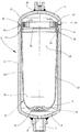
- the illustrated embodiment of the hydraulic accumulator according to the invention comprises a two-part housing 2 made of metallic material, which extends along a longitudinal axis 4 and has a main part in the form of a circular cylindrical pot 6 with a bottom part 8. This is arched in a circular arc and closed except for a coaxial to the axis 4 connection 10, which forms the hydraulic fluid access to the liquid side 12 in the housing 2.
- a head part 14 is welded to the edge of the pot 6 at the open end of the pot 6 along a welding region 16, in the present example by means of an electron-welding process.
- the head part 14 which has a similar curved shape as the bottom part 8, is closed except for a coaxial port 18, which forms the access for a working gas, such as N 2 , to the gas side 20 located inside the housing.
- a working gas such as N 2
- An optionally located on the port 18 filling valve and an associated pipe are not shown, as well as the connection of the located at the bottom part 8 terminal 10 is omitted with an associated hydraulic system.
- the housing 2 with the elongated body formed by the pot 6 is in the form of a slender storage bottle receiving within the pot 6 an elastomeric membrane 22 having a correspondingly slender, elongated shape in the undeformed state shown in the figure.
- the undeformed membrane 22 forms between its opening edge 24 and a transition point 26 to the end portion 28 a flat, elongated cone with straight generating lines 30.
- the adjoining the transition point 26, curved end portion 28 has, as in the known diaphragm accumulators, an end reinforcement 32 ,
- the membrane 22 has a bead-like thickening 34 at the opening edge 24.
- the membrane 22 is formed in the pot 6 at a small distance from the welding area 16 forming pot end in the inner wall an annular groove-like notch 36 which forms a seat for the bead-like thickening 34.
- a retaining ring 38 which has a holding part 40 which forms a from the outer periphery of the retaining ring 38 inwardly offset, partially enclosing the inside of the thickening 34.
- the retaining ring 38 Extending axially from the holding portion 40 toward the head portion 14, the retaining ring 38 includes a rim of compliant fingers 42 separated by slots 44 and extending beyond the weld area 16.
- the fingers 42 form an annular groove 46 as a seat for a guard ring 48, which is formed by a metallic flat ring. This can be snapped by sliding over inclined surfaces at the ends of the fingers 42 in the annular groove 46.
- the membrane 22 is inserted with the pot 6 open together with the retaining ring 38 and the guard ring 48 in the pot 6, wherein in the inserted position of the guard ring 48 in a welding region 16 overlapping position.
- a plastic material may advantageously be provided a glass fiber reinforced polyarylamide.
- the undeformed membrane 22 in the direction of the axis 4 has a length which is a multiple of the diameter at the opening edge 24.
- the undeformed length is approximately 2.5 times the diameter of the free opening of the opening edge 24.
- the generatrices 30 of the opening between the edge 24th and end portion 28 extending, flat cone of the diaphragm 22 converge to the longitudinal axis 4 at a low angle, in the illustrated embodiment at an angle of 2 °. In this configuration, in comparison with the known diaphragm accumulators, an optimum ratio between the outer diameter of the housing 2 and usable volume of working gas in the gas side 20 results.
Landscapes
- Engineering & Computer Science (AREA)
- Physics & Mathematics (AREA)
- Fluid Mechanics (AREA)
- Mechanical Engineering (AREA)
- General Engineering & Computer Science (AREA)
- Supply Devices, Intensifiers, Converters, And Telemotors (AREA)
Applications Claiming Priority (1)
| Application Number | Priority Date | Filing Date | Title |
|---|---|---|---|
| DE102017006064.9A DE102017006064A1 (de) | 2017-06-27 | 2017-06-27 | Hydrospeicher |
Publications (2)
| Publication Number | Publication Date |
|---|---|
| EP3421818A1 true EP3421818A1 (fr) | 2019-01-02 |
| EP3421818B1 EP3421818B1 (fr) | 2021-12-29 |
Family
ID=62684636
Family Applications (1)
| Application Number | Title | Priority Date | Filing Date |
|---|---|---|---|
| EP18177868.9A Active EP3421818B1 (fr) | 2017-06-27 | 2018-06-14 | Accumulateur hydraulique |
Country Status (3)
| Country | Link |
|---|---|
| EP (1) | EP3421818B1 (fr) |
| DE (1) | DE102017006064A1 (fr) |
| MA (1) | MA46372A (fr) |
Cited By (1)
| Publication number | Priority date | Publication date | Assignee | Title |
|---|---|---|---|---|
| WO2025247666A3 (fr) * | 2024-05-28 | 2026-02-19 | Hydac Technology Gmbh | Procédé |
Families Citing this family (1)
| Publication number | Priority date | Publication date | Assignee | Title |
|---|---|---|---|---|
| DE102021000139A1 (de) | 2021-01-14 | 2022-07-14 | Hydac Technology Gmbh | Hydrospeicher |
Citations (3)
| Publication number | Priority date | Publication date | Assignee | Title |
|---|---|---|---|---|
| DE1525961A1 (de) * | 1967-02-24 | 1970-01-15 | Elmer Dipl Ing Adam | Hydrospeicher |
| DE2604959A1 (de) * | 1975-02-24 | 1976-09-02 | Greer Hydraulics Inc | Druckbehaelter und verfahren zu seiner herstellung |
| DE4131524A1 (de) * | 1991-09-21 | 1993-04-01 | Hydac Technology Gmbh | Membranspeicher mit befestigungsring |
Family Cites Families (4)
| Publication number | Priority date | Publication date | Assignee | Title |
|---|---|---|---|---|
| US3847182A (en) * | 1973-06-18 | 1974-11-12 | E Greer | Hydro-pneumatic flexible bladder accumulator |
| US4427028A (en) * | 1979-11-13 | 1984-01-24 | Vsi Corporation | Resistance welded accumulator device |
| DE3404897A1 (de) | 1984-02-11 | 1985-08-14 | Integral Hydraulik & Co, 4000 Düsseldorf | Hydrospeicher |
| DE29718588U1 (de) * | 1997-10-20 | 1998-01-15 | Böhm, Klaus, 09128 Chemnitz | Hydropneumatischer Druckspeicher |
-
2017
- 2017-06-27 DE DE102017006064.9A patent/DE102017006064A1/de not_active Withdrawn
-
2018
- 2018-06-14 EP EP18177868.9A patent/EP3421818B1/fr active Active
- 2018-06-14 MA MA046372A patent/MA46372A/fr unknown
Patent Citations (3)
| Publication number | Priority date | Publication date | Assignee | Title |
|---|---|---|---|---|
| DE1525961A1 (de) * | 1967-02-24 | 1970-01-15 | Elmer Dipl Ing Adam | Hydrospeicher |
| DE2604959A1 (de) * | 1975-02-24 | 1976-09-02 | Greer Hydraulics Inc | Druckbehaelter und verfahren zu seiner herstellung |
| DE4131524A1 (de) * | 1991-09-21 | 1993-04-01 | Hydac Technology Gmbh | Membranspeicher mit befestigungsring |
Cited By (1)
| Publication number | Priority date | Publication date | Assignee | Title |
|---|---|---|---|---|
| WO2025247666A3 (fr) * | 2024-05-28 | 2026-02-19 | Hydac Technology Gmbh | Procédé |
Also Published As
| Publication number | Publication date |
|---|---|
| EP3421818B1 (fr) | 2021-12-29 |
| MA46372A (fr) | 2019-08-07 |
| DE102017006064A1 (de) | 2018-12-27 |
Similar Documents
| Publication | Publication Date | Title |
|---|---|---|
| DE102010021667B4 (de) | Druckbehälter für gasförmige oder flüssige Medien | |
| DE102014207069A1 (de) | Anschlusselement für einen Drucktank sowie Drucktank | |
| DE102011102154A1 (de) | Verbinder für eine Fluidleitung und Fluidleitung | |
| EP2697131B1 (fr) | Fermeture de recipient de type tube avec un mecanisme de soupape | |
| DE112008000804B4 (de) | Anschlussvorrichtung für Medienleitungen im Bereich einer Wandungsdurchführung | |
| EP3421818B1 (fr) | Accumulateur hydraulique | |
| EP2519746B1 (fr) | Accumulateur hydraulique, en particulier amortisseur de pulsations | |
| EP4229302B1 (fr) | Accumulateur hydraulique | |
| EP3334513A1 (fr) | Dispositif filtrant et élément filtrant | |
| EP2670614B1 (fr) | Filtre destiné à être introduit dans la tubulure de remplissage d'un récipient | |
| EP2588762B1 (fr) | Accumulateur de pression et pièce d'insertion pour accumulateur de pression | |
| DE102011117752A1 (de) | Hydrospeicher in Form eines Balgspeichers | |
| DE2009487C3 (de) | Druckbehälter | |
| EP2519747B1 (fr) | Dispositif de guidage pour soufflet métallique | |
| DE102015010533A1 (de) | Filtervorrichtung nebst Filterelement | |
| EP3334515B1 (fr) | Dispositif filtrant | |
| EP3795227B1 (fr) | Dispositif filtrant | |
| EP1836432A1 (fr) | Armature servant a former un raccord fluidique | |
| DE1430437A1 (de) | Hauptzylinder fuer hydraulische Betaetigungsanlagen,z.B. Geberzylinder fuer die Betaetigung von hydraulischen Bremsen oder Kupplungen in Fahrzeugen | |
| DE2738684A1 (de) | Hydropneumatischer druckspeicher mit einsatz im anschlusstueck | |
| WO2016008741A1 (fr) | Moyen formant réservoir, en particulier dans un véhicule | |
| DE102013110828B4 (de) | Einrichtung zum dichten Verschließen eines Tanks | |
| DE102015212921A1 (de) | Eisdruckschutzeinrichtung, Pumpenvorrichtung, Abgasnachbehandlungssystem | |
| DE102019215995A1 (de) | Kolbenstange für Kolbenzylinder-Aggregat mit einer internen Leitung | |
| EP4194099A1 (fr) | Porte-capsule destiné au logement d'une capsule à gaz |
Legal Events
| Date | Code | Title | Description |
|---|---|---|---|
| PUAI | Public reference made under article 153(3) epc to a published international application that has entered the european phase |
Free format text: ORIGINAL CODE: 0009012 |
|
| STAA | Information on the status of an ep patent application or granted ep patent |
Free format text: STATUS: THE APPLICATION HAS BEEN PUBLISHED |
|
| AK | Designated contracting states |
Kind code of ref document: A1 Designated state(s): AL AT BE BG CH CY CZ DE DK EE ES FI FR GB GR HR HU IE IS IT LI LT LU LV MC MK MT NL NO PL PT RO RS SE SI SK SM TR |
|
| AX | Request for extension of the european patent |
Extension state: BA ME |
|
| STAA | Information on the status of an ep patent application or granted ep patent |
Free format text: STATUS: REQUEST FOR EXAMINATION WAS MADE |
|
| 17P | Request for examination filed |
Effective date: 20190702 |
|
| RAV | Requested validation state of the european patent: fee paid |
Extension state: KH Effective date: 20190702 Extension state: MA Effective date: 20190702 Extension state: TN Effective date: 20190702 Extension state: MD Effective date: 20190702 |
|
| RBV | Designated contracting states (corrected) |
Designated state(s): AL AT BE BG CH CY CZ DE DK EE ES FI FR GB GR HR HU IE IS IT LI LT LU LV MC MK MT NL NO PL PT RO RS SE SI SK SM TR |
|
| STAA | Information on the status of an ep patent application or granted ep patent |
Free format text: STATUS: EXAMINATION IS IN PROGRESS |
|
| 17Q | First examination report despatched |
Effective date: 20200317 |
|
| GRAP | Despatch of communication of intention to grant a patent |
Free format text: ORIGINAL CODE: EPIDOSNIGR1 |
|
| STAA | Information on the status of an ep patent application or granted ep patent |
Free format text: STATUS: GRANT OF PATENT IS INTENDED |
|
| INTG | Intention to grant announced |
Effective date: 20210830 |
|
| RAP3 | Party data changed (applicant data changed or rights of an application transferred) |
Owner name: HYDAC TECHNOLOGY GMBH |
|
| DAV | Request for validation of the european patent (deleted) | ||
| GRAS | Grant fee paid |
Free format text: ORIGINAL CODE: EPIDOSNIGR3 |
|
| GRAA | (expected) grant |
Free format text: ORIGINAL CODE: 0009210 |
|
| STAA | Information on the status of an ep patent application or granted ep patent |
Free format text: STATUS: THE PATENT HAS BEEN GRANTED |
|
| AK | Designated contracting states |
Kind code of ref document: B1 Designated state(s): AL AT BE BG CH CY CZ DE DK EE ES FI FR GB GR HR HU IE IS IT LI LT LU LV MC MK MT NL NO PL PT RO RS SE SI SK SM TR |
|
| REG | Reference to a national code |
Ref country code: GB Ref legal event code: FG4D Free format text: NOT ENGLISH |
|
| REG | Reference to a national code |
Ref country code: CH Ref legal event code: EP |
|
| REG | Reference to a national code |
Ref country code: AT Ref legal event code: REF Ref document number: 1458891 Country of ref document: AT Kind code of ref document: T Effective date: 20220115 |
|
| REG | Reference to a national code |
Ref country code: IE Ref legal event code: FG4D Free format text: LANGUAGE OF EP DOCUMENT: GERMAN |
|
| REG | Reference to a national code |
Ref country code: DE Ref legal event code: R096 Ref document number: 502018008306 Country of ref document: DE |
|
| REG | Reference to a national code |
Ref country code: LT Ref legal event code: MG9D |
|
| PG25 | Lapsed in a contracting state [announced via postgrant information from national office to epo] |
Ref country code: RS Free format text: LAPSE BECAUSE OF FAILURE TO SUBMIT A TRANSLATION OF THE DESCRIPTION OR TO PAY THE FEE WITHIN THE PRESCRIBED TIME-LIMIT Effective date: 20211229 Ref country code: LT Free format text: LAPSE BECAUSE OF FAILURE TO SUBMIT A TRANSLATION OF THE DESCRIPTION OR TO PAY THE FEE WITHIN THE PRESCRIBED TIME-LIMIT Effective date: 20211229 Ref country code: FI Free format text: LAPSE BECAUSE OF FAILURE TO SUBMIT A TRANSLATION OF THE DESCRIPTION OR TO PAY THE FEE WITHIN THE PRESCRIBED TIME-LIMIT Effective date: 20211229 Ref country code: BG Free format text: LAPSE BECAUSE OF FAILURE TO SUBMIT A TRANSLATION OF THE DESCRIPTION OR TO PAY THE FEE WITHIN THE PRESCRIBED TIME-LIMIT Effective date: 20220329 |
|
| REG | Reference to a national code |
Ref country code: NL Ref legal event code: MP Effective date: 20211229 |
|
| PG25 | Lapsed in a contracting state [announced via postgrant information from national office to epo] |
Ref country code: SE Free format text: LAPSE BECAUSE OF FAILURE TO SUBMIT A TRANSLATION OF THE DESCRIPTION OR TO PAY THE FEE WITHIN THE PRESCRIBED TIME-LIMIT Effective date: 20211229 Ref country code: NO Free format text: LAPSE BECAUSE OF FAILURE TO SUBMIT A TRANSLATION OF THE DESCRIPTION OR TO PAY THE FEE WITHIN THE PRESCRIBED TIME-LIMIT Effective date: 20220329 Ref country code: LV Free format text: LAPSE BECAUSE OF FAILURE TO SUBMIT A TRANSLATION OF THE DESCRIPTION OR TO PAY THE FEE WITHIN THE PRESCRIBED TIME-LIMIT Effective date: 20211229 Ref country code: HR Free format text: LAPSE BECAUSE OF FAILURE TO SUBMIT A TRANSLATION OF THE DESCRIPTION OR TO PAY THE FEE WITHIN THE PRESCRIBED TIME-LIMIT Effective date: 20211229 Ref country code: GR Free format text: LAPSE BECAUSE OF FAILURE TO SUBMIT A TRANSLATION OF THE DESCRIPTION OR TO PAY THE FEE WITHIN THE PRESCRIBED TIME-LIMIT Effective date: 20220330 |
|
| PG25 | Lapsed in a contracting state [announced via postgrant information from national office to epo] |
Ref country code: NL Free format text: LAPSE BECAUSE OF FAILURE TO SUBMIT A TRANSLATION OF THE DESCRIPTION OR TO PAY THE FEE WITHIN THE PRESCRIBED TIME-LIMIT Effective date: 20211229 |
|
| PG25 | Lapsed in a contracting state [announced via postgrant information from national office to epo] |
Ref country code: SM Free format text: LAPSE BECAUSE OF FAILURE TO SUBMIT A TRANSLATION OF THE DESCRIPTION OR TO PAY THE FEE WITHIN THE PRESCRIBED TIME-LIMIT Effective date: 20211229 Ref country code: SK Free format text: LAPSE BECAUSE OF FAILURE TO SUBMIT A TRANSLATION OF THE DESCRIPTION OR TO PAY THE FEE WITHIN THE PRESCRIBED TIME-LIMIT Effective date: 20211229 Ref country code: RO Free format text: LAPSE BECAUSE OF FAILURE TO SUBMIT A TRANSLATION OF THE DESCRIPTION OR TO PAY THE FEE WITHIN THE PRESCRIBED TIME-LIMIT Effective date: 20211229 Ref country code: PT Free format text: LAPSE BECAUSE OF FAILURE TO SUBMIT A TRANSLATION OF THE DESCRIPTION OR TO PAY THE FEE WITHIN THE PRESCRIBED TIME-LIMIT Effective date: 20220429 Ref country code: ES Free format text: LAPSE BECAUSE OF FAILURE TO SUBMIT A TRANSLATION OF THE DESCRIPTION OR TO PAY THE FEE WITHIN THE PRESCRIBED TIME-LIMIT Effective date: 20211229 Ref country code: EE Free format text: LAPSE BECAUSE OF FAILURE TO SUBMIT A TRANSLATION OF THE DESCRIPTION OR TO PAY THE FEE WITHIN THE PRESCRIBED TIME-LIMIT Effective date: 20211229 Ref country code: CZ Free format text: LAPSE BECAUSE OF FAILURE TO SUBMIT A TRANSLATION OF THE DESCRIPTION OR TO PAY THE FEE WITHIN THE PRESCRIBED TIME-LIMIT Effective date: 20211229 |
|
| PG25 | Lapsed in a contracting state [announced via postgrant information from national office to epo] |
Ref country code: PL Free format text: LAPSE BECAUSE OF FAILURE TO SUBMIT A TRANSLATION OF THE DESCRIPTION OR TO PAY THE FEE WITHIN THE PRESCRIBED TIME-LIMIT Effective date: 20211229 |
|
| PG25 | Lapsed in a contracting state [announced via postgrant information from national office to epo] |
Ref country code: IS Free format text: LAPSE BECAUSE OF FAILURE TO SUBMIT A TRANSLATION OF THE DESCRIPTION OR TO PAY THE FEE WITHIN THE PRESCRIBED TIME-LIMIT Effective date: 20220429 |
|
| REG | Reference to a national code |
Ref country code: DE Ref legal event code: R097 Ref document number: 502018008306 Country of ref document: DE |
|
| PG25 | Lapsed in a contracting state [announced via postgrant information from national office to epo] |
Ref country code: DK Free format text: LAPSE BECAUSE OF FAILURE TO SUBMIT A TRANSLATION OF THE DESCRIPTION OR TO PAY THE FEE WITHIN THE PRESCRIBED TIME-LIMIT Effective date: 20211229 Ref country code: AL Free format text: LAPSE BECAUSE OF FAILURE TO SUBMIT A TRANSLATION OF THE DESCRIPTION OR TO PAY THE FEE WITHIN THE PRESCRIBED TIME-LIMIT Effective date: 20211229 |
|
| PLBE | No opposition filed within time limit |
Free format text: ORIGINAL CODE: 0009261 |
|
| STAA | Information on the status of an ep patent application or granted ep patent |
Free format text: STATUS: NO OPPOSITION FILED WITHIN TIME LIMIT |
|
| 26N | No opposition filed |
Effective date: 20220930 |
|
| PG25 | Lapsed in a contracting state [announced via postgrant information from national office to epo] |
Ref country code: MC Free format text: LAPSE BECAUSE OF FAILURE TO SUBMIT A TRANSLATION OF THE DESCRIPTION OR TO PAY THE FEE WITHIN THE PRESCRIBED TIME-LIMIT Effective date: 20211229 |
|
| REG | Reference to a national code |
Ref country code: CH Ref legal event code: PL |
|
| REG | Reference to a national code |
Ref country code: BE Ref legal event code: MM Effective date: 20220630 |
|
| PG25 | Lapsed in a contracting state [announced via postgrant information from national office to epo] |
Ref country code: SI Free format text: LAPSE BECAUSE OF FAILURE TO SUBMIT A TRANSLATION OF THE DESCRIPTION OR TO PAY THE FEE WITHIN THE PRESCRIBED TIME-LIMIT Effective date: 20211229 |
|
| PG25 | Lapsed in a contracting state [announced via postgrant information from national office to epo] |
Ref country code: LU Free format text: LAPSE BECAUSE OF NON-PAYMENT OF DUE FEES Effective date: 20220614 Ref country code: LI Free format text: LAPSE BECAUSE OF NON-PAYMENT OF DUE FEES Effective date: 20220630 Ref country code: IE Free format text: LAPSE BECAUSE OF NON-PAYMENT OF DUE FEES Effective date: 20220614 Ref country code: CH Free format text: LAPSE BECAUSE OF NON-PAYMENT OF DUE FEES Effective date: 20220630 |
|
| PG25 | Lapsed in a contracting state [announced via postgrant information from national office to epo] |
Ref country code: BE Free format text: LAPSE BECAUSE OF NON-PAYMENT OF DUE FEES Effective date: 20220630 |
|
| PG25 | Lapsed in a contracting state [announced via postgrant information from national office to epo] |
Ref country code: HU Free format text: LAPSE BECAUSE OF FAILURE TO SUBMIT A TRANSLATION OF THE DESCRIPTION OR TO PAY THE FEE WITHIN THE PRESCRIBED TIME-LIMIT; INVALID AB INITIO Effective date: 20180614 |
|
| PG25 | Lapsed in a contracting state [announced via postgrant information from national office to epo] |
Ref country code: MK Free format text: LAPSE BECAUSE OF FAILURE TO SUBMIT A TRANSLATION OF THE DESCRIPTION OR TO PAY THE FEE WITHIN THE PRESCRIBED TIME-LIMIT Effective date: 20211229 Ref country code: CY Free format text: LAPSE BECAUSE OF FAILURE TO SUBMIT A TRANSLATION OF THE DESCRIPTION OR TO PAY THE FEE WITHIN THE PRESCRIBED TIME-LIMIT Effective date: 20211229 |
|
| REG | Reference to a national code |
Ref country code: AT Ref legal event code: MM01 Ref document number: 1458891 Country of ref document: AT Kind code of ref document: T Effective date: 20230614 |
|
| PG25 | Lapsed in a contracting state [announced via postgrant information from national office to epo] |
Ref country code: MT Free format text: LAPSE BECAUSE OF FAILURE TO SUBMIT A TRANSLATION OF THE DESCRIPTION OR TO PAY THE FEE WITHIN THE PRESCRIBED TIME-LIMIT Effective date: 20211229 |
|
| PG25 | Lapsed in a contracting state [announced via postgrant information from national office to epo] |
Ref country code: AT Free format text: LAPSE BECAUSE OF NON-PAYMENT OF DUE FEES Effective date: 20230614 |
|
| PG25 | Lapsed in a contracting state [announced via postgrant information from national office to epo] |
Ref country code: AT Free format text: LAPSE BECAUSE OF NON-PAYMENT OF DUE FEES Effective date: 20230614 |
|
| PGFP | Annual fee paid to national office [announced via postgrant information from national office to epo] |
Ref country code: DE Payment date: 20250630 Year of fee payment: 8 |
|
| PGFP | Annual fee paid to national office [announced via postgrant information from national office to epo] |
Ref country code: GB Payment date: 20250408 Year of fee payment: 8 |
|
| PGFP | Annual fee paid to national office [announced via postgrant information from national office to epo] |
Ref country code: FR Payment date: 20250407 Year of fee payment: 8 |
|
| PGFP | Annual fee paid to national office [announced via postgrant information from national office to epo] |
Ref country code: IT Payment date: 20250606 Year of fee payment: 8 |
|
| PG25 | Lapsed in a contracting state [announced via postgrant information from national office to epo] |
Ref country code: TR Free format text: LAPSE BECAUSE OF FAILURE TO SUBMIT A TRANSLATION OF THE DESCRIPTION OR TO PAY THE FEE WITHIN THE PRESCRIBED TIME-LIMIT Effective date: 20211229 |
|
| PGFP | Annual fee paid to national office [announced via postgrant information from national office to epo] |
Ref country code: AT Payment date: 20260410 Year of fee payment: 5 |