EP3421884A1 - Appareil de refroidissement de structure inférieure pour générateur de vapeur de réacteur nucléaire - Google Patents
Appareil de refroidissement de structure inférieure pour générateur de vapeur de réacteur nucléaire Download PDFInfo
- Publication number
- EP3421884A1 EP3421884A1 EP17756779.9A EP17756779A EP3421884A1 EP 3421884 A1 EP3421884 A1 EP 3421884A1 EP 17756779 A EP17756779 A EP 17756779A EP 3421884 A1 EP3421884 A1 EP 3421884A1
- Authority
- EP
- European Patent Office
- Prior art keywords
- stud bolt
- hole
- steam generator
- axial
- skirt
- Prior art date
- Legal status (The legal status is an assumption and is not a legal conclusion. Google has not performed a legal analysis and makes no representation as to the accuracy of the status listed.)
- Withdrawn
Links
- 238000001816 cooling Methods 0.000 title claims abstract description 37
- 230000000694 effects Effects 0.000 claims description 9
- 230000017525 heat dissipation Effects 0.000 claims description 8
- 230000007423 decrease Effects 0.000 claims description 3
- 239000003570 air Substances 0.000 description 40
- 239000002826 coolant Substances 0.000 description 16
- 238000010586 diagram Methods 0.000 description 7
- 238000009413 insulation Methods 0.000 description 6
- 238000000034 method Methods 0.000 description 4
- 208000025599 Heat Stress disease Diseases 0.000 description 3
- 238000010276 construction Methods 0.000 description 3
- 230000002787 reinforcement Effects 0.000 description 3
- BTBUEUYNUDRHOZ-UHFFFAOYSA-N Borate Chemical compound [O-]B([O-])[O-] BTBUEUYNUDRHOZ-UHFFFAOYSA-N 0.000 description 2
- 239000012080 ambient air Substances 0.000 description 2
- 230000008602 contraction Effects 0.000 description 2
- 239000000463 material Substances 0.000 description 2
- 238000012986 modification Methods 0.000 description 2
- 230000004048 modification Effects 0.000 description 2
- 239000007787 solid Substances 0.000 description 2
- 238000012360 testing method Methods 0.000 description 2
- 238000012546 transfer Methods 0.000 description 2
- 238000003466 welding Methods 0.000 description 2
- 238000007792 addition Methods 0.000 description 1
- KGBXLFKZBHKPEV-UHFFFAOYSA-N boric acid Chemical compound OB(O)O KGBXLFKZBHKPEV-UHFFFAOYSA-N 0.000 description 1
- 239000004327 boric acid Substances 0.000 description 1
- 238000002485 combustion reaction Methods 0.000 description 1
- 238000013461 design Methods 0.000 description 1
- 238000009434 installation Methods 0.000 description 1
- 239000012774 insulation material Substances 0.000 description 1
- 230000002452 interceptive effect Effects 0.000 description 1
- 238000009428 plumbing Methods 0.000 description 1
- 230000005855 radiation Effects 0.000 description 1
- 238000007665 sagging Methods 0.000 description 1
- 238000006467 substitution reaction Methods 0.000 description 1
- 230000001629 suppression Effects 0.000 description 1
- XLYOFNOQVPJJNP-UHFFFAOYSA-N water Substances O XLYOFNOQVPJJNP-UHFFFAOYSA-N 0.000 description 1
Images


Classifications
-
- G—PHYSICS
- G21—NUCLEAR PHYSICS; NUCLEAR ENGINEERING
- G21C—NUCLEAR REACTORS
- G21C13/00—Pressure vessels; Containment vessels; Containment in general
- G21C13/02—Details
- G21C13/024—Supporting constructions for pressure vessels or containment vessels
-
- F—MECHANICAL ENGINEERING; LIGHTING; HEATING; WEAPONS; BLASTING
- F22—STEAM GENERATION
- F22B—METHODS OF STEAM GENERATION; STEAM BOILERS
- F22B37/00—Component parts or details of steam boilers
- F22B37/02—Component parts or details of steam boilers applicable to more than one kind or type of steam boiler
- F22B37/24—Supporting, suspending or setting arrangements, e.g. heat shielding
-
- F—MECHANICAL ENGINEERING; LIGHTING; HEATING; WEAPONS; BLASTING
- F22—STEAM GENERATION
- F22B—METHODS OF STEAM GENERATION; STEAM BOILERS
- F22B37/00—Component parts or details of steam boilers
- F22B37/02—Component parts or details of steam boilers applicable to more than one kind or type of steam boiler
-
- G—PHYSICS
- G21—NUCLEAR PHYSICS; NUCLEAR ENGINEERING
- G21C—NUCLEAR REACTORS
- G21C15/00—Cooling arrangements within the pressure vessel containing the core; Selection of specific coolants
- G21C15/24—Promoting flow of the coolant
- G21C15/253—Promoting flow of the coolant for gases, e.g. blowers
-
- G—PHYSICS
- G21—NUCLEAR PHYSICS; NUCLEAR ENGINEERING
- G21D—NUCLEAR POWER PLANT
- G21D1/00—Details of nuclear power plant
-
- F—MECHANICAL ENGINEERING; LIGHTING; HEATING; WEAPONS; BLASTING
- F22—STEAM GENERATION
- F22B—METHODS OF STEAM GENERATION; STEAM BOILERS
- F22B37/00—Component parts or details of steam boilers
- F22B37/002—Component parts or details of steam boilers specially adapted for nuclear steam generators, e.g. maintenance, repairing or inspecting equipment not otherwise provided for
-
- F—MECHANICAL ENGINEERING; LIGHTING; HEATING; WEAPONS; BLASTING
- F22—STEAM GENERATION
- F22B—METHODS OF STEAM GENERATION; STEAM BOILERS
- F22B37/00—Component parts or details of steam boilers
- F22B37/02—Component parts or details of steam boilers applicable to more than one kind or type of steam boiler
- F22B37/24—Supporting, suspending or setting arrangements, e.g. heat shielding
- F22B37/242—Supporting, suspending or setting arrangements, e.g. heat shielding for bottom supported water-tube steam generators
-
- Y—GENERAL TAGGING OF NEW TECHNOLOGICAL DEVELOPMENTS; GENERAL TAGGING OF CROSS-SECTIONAL TECHNOLOGIES SPANNING OVER SEVERAL SECTIONS OF THE IPC; TECHNICAL SUBJECTS COVERED BY FORMER USPC CROSS-REFERENCE ART COLLECTIONS [XRACs] AND DIGESTS
- Y02—TECHNOLOGIES OR APPLICATIONS FOR MITIGATION OR ADAPTATION AGAINST CLIMATE CHANGE
- Y02E—REDUCTION OF GREENHOUSE GAS [GHG] EMISSIONS, RELATED TO ENERGY GENERATION, TRANSMISSION OR DISTRIBUTION
- Y02E30/00—Energy generation of nuclear origin
- Y02E30/30—Nuclear fission reactors
Definitions
- the present invention relates to an apparatus for cooling a substructure positioned underneath a steam generator in a nuclear reactor. More particularly, the present invention relates to an apparatus for cooling a substructure of a steam generator in a nuclear reactor, wherein a stud bolt for connecting a skirt and a sliding base of the steam generator in a nuclear reactor is provided with a venturi-type axial through hole and a plurality of inclined vent holes, a skirt flange is provided on one side thereof with a vent passage, and the skirt is provided on the bottom thereof with a plurality of air-passing grooves such that an air circulation/cooling path is formed between a dead air region in the substructure and surroundings through the axial through hole via the inclined vent holes, the air-passing grooves, and the vent passage, thereby cooling the stud bolt and the sliding base to prevent them from being thermally damaged and thus improve operating stability of a nuclear reactor system facility.
- exemplary nuclear reactors in South Korea include System Plus 80 from Combustion Engineering (CE) (e.g. Hanbit Nuclear Power Plant (NPP) Units 3 and 4), Korean Standard Nuclear Reactors (e.g. Hanul NPP Units 3, 4, 5, and 6; Hanbit NPP Units 5 and 6), OPR1000 (e.g. new Kori NPP Units 1 and 2), APR1400 (new Kori Units 3 and 4, new Ulgin Units 1 and 2, UAE NPP Units 1 to 4), 2-loop Pressurized Water Reactor, etc.
- CE Combustion Engineering
- NPP Hanbit Nuclear Power Plant
- Korean Standard Nuclear Reactors e.g. Hanul NPP Units 3, 4, 5, and 6; Hanbit NPP Units 5 and 6
- OPR1000 e.g. new Kori NPP Units 1 and 2
- APR1400 new Kori Units 3 and 4, new Ulgin Units 1 and 2, UAE NPP Units 1 to 4
- 2-loop Pressurized Water Reactor etc.
- NPPs include reactor coolant systems (RCSs) in reactor containment buildings as also disclosed in Korean Patent No. 10-1473665 entitled “Tubing Support Apparatus for Replacement of Parts of Nuclear Power Plant”.
- RCSs reactor coolant systems
- the RCS includes a reactor containing atomic piles and at least one heat-transfer circuit connected thereto.
- the circuit includes a steam generator and at least one coolant pump that circulates coolant between the steam generator and the reactor.
- the circuit includes a pressurizer that allows the temperature and pressure of the coolant to be kept constant.
- a first large-diameter pipe or a hot leg is connected to one side of the reactor and one side of a suction part of a coolant chamber in the steam generator so as to transmit the coolant, which is heated with contact with a core of the reactor, to the steam generator.
- a circulation pipe called a cross-over leg connects one side of an outlet of the coolant chamber and one side of an inlet of a swirl chamber in the coolant chamber.
- a cold leg connects the swirl chamber in the coolant chamber and the reactor.
- the coolant that is cooled at the steam generator and drawn by the coolant pump is transmitted to the reactor via the circulation pipe and the cold leg to cool the core.
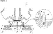
- the steam generator 1 has a typical substructure as shown in FIG. 1 .
- the steam generator 1 of the nuclear reactor 1 includes a stay cylinder 10 that is maintained at high temperature and a cylindrical skirt 20 that supports the stay cylinder from a lower section thereof.
- the skirt 20 is fixedly supported at the bottom thereof by a sliding base 30 by means of a plurality of stud bolts 40.
- the sliding base 30 is supported by a plurality of (e.g. four) semi-spherical sliders 52, which is provided on a forged bolted plate 50 so as to accommodate a slight motion occurring during the operation of a nuclear reactor.
- the stud bolt 40 has a conventional solid bolt structure.
- the steam generator produces high temperature heat that, when transmitted to the lower side sliding base 30, elevates the temperature of the sliding base 30 as shown in a heat analysis thermal distribution diagram of FIG. 2a .
- the heat analysis thermal distribution diagram shows that, as a result of analysis with respect of an insulation state, an operation temperature, material, heat transfer, an air flow around a steam generator, etc, a dead air region 70 defined by the skirt 20 and the sliding base 30 is heated to high temperature of up to 131 °C through convection and radiation of high temperature heat (300 °C or more) from the steam generator 1. It could be seen that in such a high temperature state, the skirt 20 was subjected to thermal deformation (e.g. thermal expansion of up to 2.4 mm).
- thermal deformation e.g. thermal expansion of up to 2.4 mm
- the thermal deformation of the sliding base 30 also causes serious problems as follows.
- the thermal deformation, such as thermal expansion, of the sliding base 30 causes restriction to a free motion of the sliding base 30 or interference with an upper surrounding structure of the steam generator 1, resulting in structural vibration of the steam generator 1 and the coolant pump.
- the structural vibration causes pipe wearing and vibration stress to the steam generator 1 and after a long operation time, causes material fatigue of small-diameter pipes that have borate embrittlement due to accumulated borate, leading to leakage of a boric acid solution.
- Such subsidence of the sliding base may be considered as residual stress of the sliding base 30, and it increases friction force with respect to the sliding base at an initial operating stage of a nuclear reactor, interfering with a transverse sliding motion of the sliding base.
- thermal deformation of the sliding base also causes the operating steam generator to be tilted, which may lead to misalignment of parts even after cold shutdown of the steam generator.
- a leak may occur from a mechanical seal of a coolant pump and small-diameter pipes in the nuclear reactor.
- a first solution is an air-circulation sleeve 80 that is installed through the center of a sliding base 30 supporting a steam generator to naturally circulate air using a venture effect. This enables a dead air region 70 defined by a stay cylinder and a skirt 20 of the steam generator 1 to be cooled to effectively prevent high temperature heat from being transferred to the sliding base 30 from the steam generator 1, thereby preventing vibrations of a nuclear reactor due to thermal expansion of the sliding base 30.
- a second solution is an air-circulating shim plate (not shown) between the bottom of the skirt 20 supporting the steam generator 1 and an engaging surface of the sliding base 30 to allow ambient air to be introduced into a dead air region 70 defined by a stay cylinder and a skirt 20 of the steam generator 1 to be cooled to effectively prevent high temperature heat from being transferred to the sliding base 30 from the steam generator 1, thereby preventing vibrations of a nuclear reactor due to thermal expansion of the sliding base 30.
- a third solution is a heat insulation support plate 90 that is closely attached to a lower portion of the steam generator near the stay cylinder and the skirt.
- the heat insulation support plate is composed of a heat insulation material, a heat shield panel, and a plurality of rigid pieces. The heat insulation support plate is thus prevented from sagging due to operating vibration of a nuclear reactor.
- the heat insulation support plate serves to effectively prevent high temperature heat from being transferred to the sliding base 30 through the dead air region 70, thereby preventing vibrations of a nuclear reactor due to thermal expansion of the sliding base 30.
- an object of the present invention is to provide an apparatus for cooling a substructure of a steam generator in a nuclear reactor, the apparatus being easily applicable instantly to a nuclear reactor to reduce wear of a heat pipe of a nuclear reactor and further improve operation stability of a nuclear reactor system facility without large-scale replacement and reinforcement of nuclear equipment.
- Another object of the present invention is to provide an apparatus for cooling a substructure of a steam generator in a nuclear reactor, the apparatus being applicable even to a nuclear reactor that is under construction, at a test run stage, or just before replacement of a steam generator to greatly reduce temperature of a dead air region to prevent heat fatigue of stud bolts and resultant thermal deformation of a sliding base with a simple structural feature.
- the present invention provides an apparatus for cooling a substructure of a steam generator in a nuclear reactor, the apparatus including:
- the axial through hole may have a venturi-type neck part whose internal flow passage has a reduced diameter to enable air flowing through the flow passage of the neck part to increase in a flow rate and decrease in pressure.
- a flange of the skirt may be further provided on one side thereof with a vent passage, and each stud bolt may be further provided with a plurality of vent holes communicating with the axial through hole, thereby forming an air circulation/cooling path between the vent passage and the axial through hole via the vent holes.
- the vent holes may be disposed in the stud bolt at different positions both in an axial direction and a circumferential direction while extending slantingly from an outer circumference of the stud bolt downwards to the axial through hole, thereby preventing the vent holes in the stud bolt from overlapping with each other in a horizontal direction of the stud bolt and from being circumferentially skewed in one side of the stud bolt and preventing a local reduction in strength of the stud bolt in the horizontal direction.
- the skirt may be further provided on the bottom thereof with a plurality of air-passing grooves to form an air circulation/cooling path between a dead air region defined below the steam generator and a circumferential gap between a bolt hole of the skirt and the outer circumference of the stud bolt, thereby forming an air circulation/cooling path between the dead air region and surroundings via the air-passing grooves, the circumferential gap, the vent holes, the through hole, and the vent passage.
- the stud bolt may further have a heat sink coupled to an upper threaded part of the stud bolt, wherein the heat sink is provided, on an outer surface of a body thereof coupled to the upper threaded part, with a plurality of heat-dissipation fins to increase a heat-dissipation surface area of the stud bolt to increase a cooling effect.
- the stud bolt for connecting the skirt and the sliding base of the steam generator in a nuclear reactor is provided with the axial through hole and the plurality of vent holes to form an air circulation/cooling path in an axial direction of the stud bolt, thereby cooling the stud bolt and the sliding base and thus effectively preventing thermal deformation thereof.
- the vent passage is formed in one side of the skirt flange and the plurality of air-passing grooves are formed on the bottom of the skirt to form an air circulation/cooling path between the dead air region below the steam generator and the circular gap between the bolt hole of the skirt and the outer circumference of the stud bolt.
- the heat sink is coupled to the upper threaded part of the stud bolt.
- the apparatus of the present invention is easily applicable to a nuclear reactor to greatly reduce the temperature of the dead air region without large-scale replacement and reinforcement of nuclear equipment, thereby preventing heat fatigue of the stud bolt and resultant thermal deformation of the sliding base.
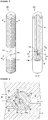
- an apparatus 100 for cooling a substructure of a steam generator in a nuclear reactor includes a plurality of stud bolts 110 that fastens a skirt 20 of the steam generator 1 to a sliding base 30, wherein each of the stud bolts is provided with a venturi-type axial through hole 112 at the center thereof.
- the stud bolts 110 are disposed around the skirt 20 of the steam generator 1, and each of the stud bolts has the axial through hole 112.
- the axial through hole 112 has a venturi-type internal flow passage that is provided with a neck part 112a having a reduced diameter.
- the neck part 112a has a length of about 30 mm, and air flowing through the neck part increases in a flow rate and decreases in pressure.
- a vent pipe (not shown) extending from a fan may be additionally connected to an upper side of the axial through hole 112 so that air can be forcefully circulated.
- a flange 22 of the skirt is provided on one side thereof with a vent passage 122 that extends to a bolt hole of the skirt 20, through which the stud bolt 110 is threaded.
- the stud bolt 112 is provided with a plurality of vent holes 114 communicating with the axial through hole 112.
- the plurality of vent holes 114 may extend in an inclined manner.
- the vent holes 114 may have an inclination ( ⁇ 1) of about 30 degrees, for example, in an upper to lower direction, and have different positions in an axial direction of the stud bolt.
- vent holes 114 are disposed in the stud bolt 110 at different positions both in an axial direction and a circumferential direction of the stud bolt while extending slantingly at an angle ( ⁇ 1) of about 30 degrees from an outer circumference of the stud bolt 110 downwards to the axial through hole 112.
- end points the vent holes 114 at the neck part 112a of the axial through hole 112 are vertically spaced by a height (h) of about 15 mm, thereby being disposed at different vertical positions.
- vent holes 114 have an inclination angle ( ⁇ 1) of about 30 degrees and a height (h) difference of about 15 mm can allow the strength of the stud bolt 110 to be maintained satisfactorily without making a cross section of the stud bolt fragile, compared to a horizontally extended vent holes.
- vent holes 114 are spaced apart at an angle ( ⁇ 2) of at least about 60 degrees from each other in a circumferential direction of the stud bolt 110.
- the circumferentially spaced angle ( ⁇ 2) prevents internal spaced of the vent holes 114 from being circumferentially skewed in one side of the stud bolt 110, thereby preventing a local reduction in strength of the stud bolt 110.
- an air circulation/cooling path is formed between the vent passage 122 and the axial through hole 112 via the circumferential gap P between the bolt hole of the skirt 20 and the outer circumference of the stud bolt 110, and the plurality of vent holes 114.
- ambient air may be naturally circulated or supplied through the vent passage 122.
- a vent pipe (not shown) is connected between the upper side of the axial through hole 112 of the stud bolt 110 and a fan, and air is sucked by the fan, as illustrated in FIG. 7 , forced air-circulation may be carried out through the stud bolt 110.
- the skirt may be further provided on the bottom 24 thereof with a plurality of air-passing grooves 124.
- the air-passing grooves 124 are formed by cutting thereby to form an air circulation/cooling path between a dead air region 70 defined below the steam generator 1 and the circumferential gap P between the bolt hole of the skirt 20 and the outer circumference of the stud bolt 110, thereby allowing air-circulation therethrough.
- an air circulation/cooling path may be formed between the dead air region 70 and surroundings via the air-passing grooves 124, the circumferential gap P between the bolt hole of the skirt 20 and the outer circumference of the stud bolt 110, the vent holes 114, the through hole 112, and the vent passage 122 in the skirt flange 22.
- forced air-circulation may be formed from the dead air region 70 below the steam generator 1 towards surroundings via the air-passing grooves 124, the circumferential gap P between the bolt hole of the skirt 20 and the outer circumference of the stud bolt 110, the plurality of vent holes 114, and the axial through hole 112.
- the stud bolt 110 may further have a heat sink 140 coupled to an upper threaded part of the stud bolt 110.
- the heat sink 140 serves as an additional heat-dissipation device that is provided, on an outer surface of a body thereof coupled to the upper threaded part, with a plurality of heat-dissipation fins 142.
- the heat sink 140 can increase a heat-dissipation surface area of the stud bolt 110 to increase a cooling effect.
- the stud bolt is provided with an air circulation/cooling path through the stud bolt 110, thereby cooling the stud bolt 110 and the sliding base 30 and thus effectively preventing thermal deformation thereof, and improving operating stability of a nuclear reactor system facility as well.
- the apparatus of the present invention is easily applicable to a nuclear reactor to greatly reduce the temperature of the dead air region without large-scale replacement and reinforcement of nuclear equipment, thereby preventing heat fatigue of the stud bolt 110 and resultant thermal deformation of the sliding base 20.
- the cooling effect for the stud bolt 110 and the sliding base 30 according to the present invention was shown through a heat analysis thermal distribution diagram of FIG. 2b .
- the cooling effect showed an excellent result in that the temperature of the dead air region 70 defined by the skirt 20 and the sliding base 30 according to the present invention was reduced by about 40% compared to that (up to 131 °C) of a conventional nuclear reactor.
Landscapes
- Engineering & Computer Science (AREA)
- Physics & Mathematics (AREA)
- General Engineering & Computer Science (AREA)
- Plasma & Fusion (AREA)
- High Energy & Nuclear Physics (AREA)
- Thermal Sciences (AREA)
- Mechanical Engineering (AREA)
- Structure Of Emergency Protection For Nuclear Reactors (AREA)
- Heat-Exchange Devices With Radiators And Conduit Assemblies (AREA)
Applications Claiming Priority (2)
| Application Number | Priority Date | Filing Date | Title |
|---|---|---|---|
| KR1020160021202A KR101653942B1 (ko) | 2016-02-23 | 2016-02-23 | 원자로 증기 발생기의 하부 구조물 냉각장치 |
| PCT/KR2017/001895 WO2017146441A1 (fr) | 2016-02-23 | 2017-02-21 | Appareil de refroidissement de structure inférieure pour générateur de vapeur de réacteur nucléaire |
Publications (2)
| Publication Number | Publication Date |
|---|---|
| EP3421884A1 true EP3421884A1 (fr) | 2019-01-02 |
| EP3421884A4 EP3421884A4 (fr) | 2019-10-16 |
Family
ID=56943219
Family Applications (1)
| Application Number | Title | Priority Date | Filing Date |
|---|---|---|---|
| EP17756779.9A Withdrawn EP3421884A4 (fr) | 2016-02-23 | 2017-02-21 | Appareil de refroidissement de structure inférieure pour générateur de vapeur de réacteur nucléaire |
Country Status (5)
| Country | Link |
|---|---|
| US (1) | US10753601B2 (fr) |
| EP (1) | EP3421884A4 (fr) |
| JP (1) | JP2019509499A (fr) |
| KR (1) | KR101653942B1 (fr) |
| WO (1) | WO2017146441A1 (fr) |
Cited By (1)
| Publication number | Priority date | Publication date | Assignee | Title |
|---|---|---|---|---|
| CN111140836A (zh) * | 2019-12-04 | 2020-05-12 | 深圳中广核工程设计有限公司 | 核电站蒸汽发生器套筒支撑装置及其安装方法 |
Families Citing this family (3)
| Publication number | Priority date | Publication date | Assignee | Title |
|---|---|---|---|---|
| CN108766593B (zh) * | 2018-07-20 | 2024-08-16 | 中广核研究院有限公司 | 一种反应堆压力容器的堆内构件结构 |
| CN111933316B (zh) * | 2020-08-12 | 2023-06-02 | 三门核电有限公司 | 一种压水堆反应堆堆腔区域高效冷却的方法 |
| KR102852693B1 (ko) * | 2024-01-24 | 2025-08-29 | 한국수력원자력 주식회사 | 증기발생기의 급수 고갈 완화를 위한 공랭식 히트파이프 냉각장치 |
Family Cites Families (16)
| Publication number | Priority date | Publication date | Assignee | Title |
|---|---|---|---|---|
| US3549493A (en) * | 1969-01-22 | 1970-12-22 | Atomic Energy Commission | Fast sodium-cooled reactor core structure |
| US3851626A (en) * | 1972-10-05 | 1974-12-03 | Westinghouse Electric Corp | Support for a steam generator |
| US3979866A (en) * | 1973-10-23 | 1976-09-14 | Nuclear Power Co. (Whetstone) Limited | Nuclear reactors |
| FR2422228A1 (fr) * | 1978-04-07 | 1979-11-02 | Commissariat Energie Atomique | Perfectionnement aux structures de calorifugeage de surfaces dans un reacteur nucleaire, notamment du genre a neutrons rapides |
| US4654188A (en) * | 1985-01-11 | 1987-03-31 | Westinghouse Electric Corp. | Pivotably mounted reactor shroud shield and shielding method |
| JPH02243994A (ja) * | 1990-01-10 | 1990-09-28 | Fuji Electric Co Ltd | ガス冷却型原子炉の炉心支持装置 |
| JP3004430B2 (ja) * | 1991-11-11 | 2000-01-31 | 中部電力株式会社 | フィルタ逆洗装置 |
| JPH0720239U (ja) * | 1993-09-14 | 1995-04-11 | エンシュウ株式会社 | 送りねじの熱変位抑制装置 |
| KR19980053115U (ko) * | 1996-12-31 | 1998-10-07 | 라제훈 | 현금 및 수표 자동지급기용 잼 자동제거장치 |
| JP3679881B2 (ja) * | 1997-02-17 | 2005-08-03 | 三菱重工業株式会社 | スタッドボルト取扱装置 |
| US5930320A (en) * | 1997-05-01 | 1999-07-27 | General Electric Company | Assemblies and methods for mitigating effects of reactor pressure vessel expansion |
| US6888909B2 (en) * | 2002-05-03 | 2005-05-03 | Westinghouse Electric Company Llc | Reactor pressure vessel |
| FR2841367B1 (fr) * | 2002-06-11 | 2005-03-18 | Framatome Anp | Dispositif de positionnement et d'alignement axial d'un assemblage de combustible et procede et dispositif de reconstitution d'un element de positionnement |
| DE102005037589B4 (de) * | 2005-08-05 | 2009-02-05 | Areva Np Gmbh | Abdeckelement für den Reaktorkern einer kerntechnischen Anlage sowie Kernreaktor |
| US9875817B2 (en) * | 2014-06-09 | 2018-01-23 | Bwxt Mpower, Inc. | Nuclear reactor support and seismic restraint with in-vessel core retention cooling features |
| KR101744318B1 (ko) * | 2016-07-27 | 2017-06-07 | 한국전력기술 주식회사 | 관류식 증기발생기 외부 일체화 소형 모듈화 원자로 |
-
2016
- 2016-02-23 KR KR1020160021202A patent/KR101653942B1/ko active Active
-
2017
- 2017-02-21 JP JP2018562487A patent/JP2019509499A/ja active Pending
- 2017-02-21 WO PCT/KR2017/001895 patent/WO2017146441A1/fr not_active Ceased
- 2017-02-21 US US16/078,658 patent/US10753601B2/en active Active
- 2017-02-21 EP EP17756779.9A patent/EP3421884A4/fr not_active Withdrawn
Cited By (2)
| Publication number | Priority date | Publication date | Assignee | Title |
|---|---|---|---|---|
| CN111140836A (zh) * | 2019-12-04 | 2020-05-12 | 深圳中广核工程设计有限公司 | 核电站蒸汽发生器套筒支撑装置及其安装方法 |
| CN111140836B (zh) * | 2019-12-04 | 2021-12-07 | 深圳中广核工程设计有限公司 | 核电站蒸汽发生器套筒支撑装置及其安装方法 |
Also Published As
| Publication number | Publication date |
|---|---|
| US10753601B2 (en) | 2020-08-25 |
| KR101653942B1 (ko) | 2016-09-02 |
| US20190049105A1 (en) | 2019-02-14 |
| JP2019509499A (ja) | 2019-04-04 |
| WO2017146441A1 (fr) | 2017-08-31 |
| EP3421884A4 (fr) | 2019-10-16 |
Similar Documents
| Publication | Publication Date | Title |
|---|---|---|
| US10753601B2 (en) | Lower structure cooling apparatus for nuclear reactor steam generator | |
| JP5497454B2 (ja) | 加圧水型原子炉のスカート状整流装置 | |
| JP5542062B2 (ja) | 原子炉圧力容器のための中性子遮蔽パネル | |
| US7522693B2 (en) | Passive safety-grade decay-heat removal method and decay-heat removal system for LMR with pool direct heat cooling process | |
| US8681922B2 (en) | Pressurizer with a mechanically attached surge nozzle thermal sleeve | |
| KR101618500B1 (ko) | 원자로 증기 발생기 하부의 공기 순환 장치 | |
| US20150152786A1 (en) | Drain pipe arrangement and gas turbine engine comprising a drain pipe arrangement | |
| EP2888742A2 (fr) | Système d'eau de refroidissement de composants pour centrale nucléaire | |
| KR101777522B1 (ko) | 정상운전 중 구속이 있는 증기발생기 하부지지구조의 열응력과 열변형을 방지하기 위한 설계 및 그 해석 방법 | |
| KR20170133895A (ko) | 가압경수로형 원자로 증기 발생기의 공기정체구역 공기 순환 냉각 장치 | |
| KR101860607B1 (ko) | 가압경수로형 원자로 증기 발생기 하부의 외기흡입 플레이트 장치 | |
| US3989100A (en) | Industrial technique | |
| KR101613814B1 (ko) | 2루프 가압경수로형 증기 발생기의 교체 방법 | |
| KR102295616B1 (ko) | 매립형 냉각배관을 통한 공냉식 콘크리트 냉각장치 | |
| DE102012101964A1 (de) | Flansch zur Temperaturreduktion für Dampfturbineneinlässe | |
| WO2016122104A1 (fr) | Structure de montage de matériau d'isolation thermique d'un générateur de vapeur d'un réacteur à eau légère sous pression à deux boucles | |
| US8328239B2 (en) | Mechanical assembly for securing the structural integrity of a pipe joint | |
| CN113948225B (zh) | 具有顶部热屏蔽的反应堆 | |
| KR101712917B1 (ko) | 폐열 회수 보일러 케이싱의 균열 방지를 위한 열 변형 흡수설비 | |
| JP7604003B2 (ja) | 原子炉システム | |
| CN220931097U (zh) | 一种锅炉密封结构 | |
| US4380085A (en) | Angled gas conduit | |
| Fernandez et al. | Design and analysis of a reactor pressure vessel for the Super Pressurized Water Reactor | |
| EP0905713A1 (fr) | Structure interne d'une cuve pour réacteur rapide | |
| JPH03128481A (ja) | 二重タンク型原子炉 |
Legal Events
| Date | Code | Title | Description |
|---|---|---|---|
| STAA | Information on the status of an ep patent application or granted ep patent |
Free format text: STATUS: THE INTERNATIONAL PUBLICATION HAS BEEN MADE |
|
| PUAI | Public reference made under article 153(3) epc to a published international application that has entered the european phase |
Free format text: ORIGINAL CODE: 0009012 |
|
| STAA | Information on the status of an ep patent application or granted ep patent |
Free format text: STATUS: REQUEST FOR EXAMINATION WAS MADE |
|
| 17P | Request for examination filed |
Effective date: 20180830 |
|
| AK | Designated contracting states |
Kind code of ref document: A1 Designated state(s): AL AT BE BG CH CY CZ DE DK EE ES FI FR GB GR HR HU IE IS IT LI LT LU LV MC MK MT NL NO PL PT RO RS SE SI SK SM TR |
|
| AX | Request for extension of the european patent |
Extension state: BA ME |
|
| DAV | Request for validation of the european patent (deleted) | ||
| DAX | Request for extension of the european patent (deleted) | ||
| A4 | Supplementary search report drawn up and despatched |
Effective date: 20190916 |
|
| RIC1 | Information provided on ipc code assigned before grant |
Ipc: F22B 37/24 20060101ALI20190910BHEP Ipc: G21D 1/00 20060101ALI20190910BHEP Ipc: G21C 13/024 20060101AFI20190910BHEP Ipc: F22B 37/00 20060101ALI20190910BHEP Ipc: F22B 37/02 20060101ALI20190910BHEP |
|
| STAA | Information on the status of an ep patent application or granted ep patent |
Free format text: STATUS: THE APPLICATION IS DEEMED TO BE WITHDRAWN |
|
| 18D | Application deemed to be withdrawn |
Effective date: 20200603 |