WO2017146441A1 - Appareil de refroidissement de structure inférieure pour générateur de vapeur de réacteur nucléaire - Google Patents
Appareil de refroidissement de structure inférieure pour générateur de vapeur de réacteur nucléaire Download PDFInfo
- Publication number
- WO2017146441A1 WO2017146441A1 PCT/KR2017/001895 KR2017001895W WO2017146441A1 WO 2017146441 A1 WO2017146441 A1 WO 2017146441A1 KR 2017001895 W KR2017001895 W KR 2017001895W WO 2017146441 A1 WO2017146441 A1 WO 2017146441A1
- Authority
- WO
- WIPO (PCT)
- Prior art keywords
- steam generator
- hole
- stud bolt
- vertical
- air
- Prior art date
- Legal status (The legal status is an assumption and is not a legal conclusion. Google has not performed a legal analysis and makes no representation as to the accuracy of the status listed.)
- Ceased
Links
Images


Classifications
-
- G—PHYSICS
- G21—NUCLEAR PHYSICS; NUCLEAR ENGINEERING
- G21C—NUCLEAR REACTORS
- G21C13/00—Pressure vessels; Containment vessels; Containment in general
- G21C13/02—Details
- G21C13/024—Supporting constructions for pressure vessels or containment vessels
-
- F—MECHANICAL ENGINEERING; LIGHTING; HEATING; WEAPONS; BLASTING
- F22—STEAM GENERATION
- F22B—METHODS OF STEAM GENERATION; STEAM BOILERS
- F22B37/00—Component parts or details of steam boilers
- F22B37/02—Component parts or details of steam boilers applicable to more than one kind or type of steam boiler
- F22B37/24—Supporting, suspending or setting arrangements, e.g. heat shielding
-
- F—MECHANICAL ENGINEERING; LIGHTING; HEATING; WEAPONS; BLASTING
- F22—STEAM GENERATION
- F22B—METHODS OF STEAM GENERATION; STEAM BOILERS
- F22B37/00—Component parts or details of steam boilers
- F22B37/02—Component parts or details of steam boilers applicable to more than one kind or type of steam boiler
-
- G—PHYSICS
- G21—NUCLEAR PHYSICS; NUCLEAR ENGINEERING
- G21C—NUCLEAR REACTORS
- G21C15/00—Cooling arrangements within the pressure vessel containing the core; Selection of specific coolants
- G21C15/24—Promoting flow of the coolant
- G21C15/253—Promoting flow of the coolant for gases, e.g. blowers
-
- G—PHYSICS
- G21—NUCLEAR PHYSICS; NUCLEAR ENGINEERING
- G21D—NUCLEAR POWER PLANT
- G21D1/00—Details of nuclear power plant
-
- F—MECHANICAL ENGINEERING; LIGHTING; HEATING; WEAPONS; BLASTING
- F22—STEAM GENERATION
- F22B—METHODS OF STEAM GENERATION; STEAM BOILERS
- F22B37/00—Component parts or details of steam boilers
- F22B37/002—Component parts or details of steam boilers specially adapted for nuclear steam generators, e.g. maintenance, repairing or inspecting equipment not otherwise provided for
-
- F—MECHANICAL ENGINEERING; LIGHTING; HEATING; WEAPONS; BLASTING
- F22—STEAM GENERATION
- F22B—METHODS OF STEAM GENERATION; STEAM BOILERS
- F22B37/00—Component parts or details of steam boilers
- F22B37/02—Component parts or details of steam boilers applicable to more than one kind or type of steam boiler
- F22B37/24—Supporting, suspending or setting arrangements, e.g. heat shielding
- F22B37/242—Supporting, suspending or setting arrangements, e.g. heat shielding for bottom supported water-tube steam generators
-
- Y—GENERAL TAGGING OF NEW TECHNOLOGICAL DEVELOPMENTS; GENERAL TAGGING OF CROSS-SECTIONAL TECHNOLOGIES SPANNING OVER SEVERAL SECTIONS OF THE IPC; TECHNICAL SUBJECTS COVERED BY FORMER USPC CROSS-REFERENCE ART COLLECTIONS [XRACs] AND DIGESTS
- Y02—TECHNOLOGIES OR APPLICATIONS FOR MITIGATION OR ADAPTATION AGAINST CLIMATE CHANGE
- Y02E—REDUCTION OF GREENHOUSE GAS [GHG] EMISSIONS, RELATED TO ENERGY GENERATION, TRANSMISSION OR DISTRIBUTION
- Y02E30/00—Energy generation of nuclear origin
- Y02E30/30—Nuclear fission reactors
Definitions
- the present invention relates to an apparatus for cooling an undercarriage located underneath a reactor steam generator, and more particularly in the form of Venturi in stud bolts securing the skirt and sliding base of the reactor steam generator.
- a vertical air penetration hole and a plurality of inclined through holes are formed, an air supply hole is formed at one side of the skirt flange, and a plurality of air circulation grooves are formed at the bottom of the skirt to form a nuclear reactor.
- nuclear reactor Such a nuclear power plant (hereinafter, simply referred to as “nuclear reactor”) is described in the Republic of Korea Patent Publication No. 10-1473665, "Pipe support device for replacing parts of nuclear power plant", the reactor coolant system (RCS: Reactor Coolant in the containment building System) is provided.
- RCS reactor Coolant in the containment building System
- Such a reactor coolant system has a reactor containing a reactor and at least one heat transfer circuit connected thereto.
- Each circuit includes a steam generator and at least one coolant pump for circulating coolant between the reactor and the steam generator.
- the circuit includes a pressurizer to keep the temperature and pressure of the coolant constant.
- the first large diameter pipe or hot leg is connected to one side of the reactor and the suction side of the coolant chamber of the steam generator to contact the core in the reactor to transfer the heated coolant to the steam generator.
- a circulation pipe called a cross-over leg connects one side of the discharge part of the coolant chamber of the steam generator and one side of the vortex chamber suction part of the coolant pump.
- the cold leg connects between the vortex chamber of the coolant pump and the reactor.
- the coolant cooled in the steam generator and drawn out by the coolant pump is transferred to the reactor through a circulation pipe and a low temperature pipe to cool the core.
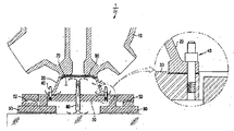
- each steam generator 1 has a typical substructure as shown in FIG. 1.
- the steam generator 1 of the reactor has a stay cylinder 10 which is maintained at a high temperature, and has a cylindrical skirt 20 which supports it at the bottom thereof.
- Such a skirt 20 is fixedly supported by a plurality of stud bolts 40 on the sliding base 30 on the lower side thereof, and such a sliding base 30 is provided on the forged bolt plate 50.
- a sliding base 30 is provided on the forged bolt plate 50.
- it is supported on four hemispherical sliders 52 so as to accommodate fine movements occurring during operation of the reactor.
- a conventional stud bolt 40 is a conventional solid bolt structure.
- the steam generator 1 generates high heat during operation.
- the sliding base 30 is heated as can be seen from the thermal analysis temperature distribution diagram of FIG. 2A. do.
- the high heat emitted from the steam generator 1 (300 ° C. or more) is determined by the skirt 20.
- thermal deformation of the sliding base 30 suppresses free movement due to thermal expansion of the sliding base 30 generated during operation of the power plant, or causes interference with surrounding structures on the upper part of the steam generator 1, and consequently steam Induce structural vibrations of the generator 1 and the coolant pump.
- the final connection welding of the intermediate pipe and the steam generator nozzle is left as a residual load on the sliding base and the pump vertical support due to the welding shrinkage.
- settlement of the sliding base 30 due to welding shrinkage occurs, and settlement typically occurs in the range of about 1 mm after installation of the steam generator and after final connection welding.
- This settlement can be seen as a load remaining on the sliding base 30, and this residual load has a characteristic of increasing the frictional force on the sliding base at the initial stage of the reactor to inhibit the sliding operation in the lateral direction.
- the steam generator will tilt and further increase the vibration stress of the reactor due to the deformation and interference of the reactor coolant pump and associated support structures of the steam generator.
- This vibration stress not only causes the tubular wear of the steam generator, but also causes wear of the reactor coolant pump's internal components and fatigue cracking by adding fatigue to the pipe connected to the RCS system.
- the air circulation sleeve 80 is mounted in the center of the sliding base 30 supporting the reactor steam generator to naturally circulate the air by the Venturi effect, so that the stay cylinder of the steam generator 1 stays. Sliding base 30 by naturally cooling the stagnated air area 70 inside the cylinder and skirt 20 and effectively preventing the transfer of high heat from the steam generator 1 to the sliding base 30. It is an air circulation sleeve device under the reactor steam generator to prevent the vibration phenomenon of the reactor due to the thermal expansion deformation of the reactor.
- an air circulation shim plate (not shown) is disposed between the lower surface of the skirt 20 supporting the reactor steam generator 1 and the engaging surface of the sliding base 30 so that the outdoor air stays.
- the reactor 90 is tightly fixed along the bottom of the steam generator.
- the sliding base It is a heat insulating material mounting structure of the reactor steam generator to prevent vibration of the reactor caused by thermal expansion deformation of 30).
- the conventional techniques proposed by the applicant of the present invention have a great effect in preventing the thermal deformation of the sliding base 30 to improve the stable operation of the reactor and the equipment life.
- An object of the present invention is to solve the conventional problems as described above, can be easily applied on-site without entailing large-scale replacement and reinforcement work of nuclear power plants, reducing the wear of the reactor heat pipe, further improve the operational stability of the reactor system equipment It is to provide a cooling device for the lower structure of the reactor steam generator improved.
- the stud bolt does not suffer from heat fatigue (heat fatigue) so that the thermal deformation of the sliding base does not occur It is to provide a cooling device for the lower structure of the reactor steam generator that can greatly reduce the temperature of the zone.
- the present invention in the device for cooling the lower structure located in the reactor steam generator,
- a plurality of stud bolts securing the skirt of the reactor steam generator to the sliding base
- the vertical through hole to form a neck of the venturi tube shape of the diameter of the inner passage is reduced to accelerate the speed of the air flow flowing in the interior of the vertical through hole, so as to lower the pressure in the neck It is composed.
- the present invention preferably further includes an air supply hole formed on one side of the skirt flange, and each stud bolt further includes a plurality of through holes communicating with the vertical through holes. And to form an air circulation / cooling passage leading from the air supply hole to the through hole and the vertical through hole.
- the through hole is formed from the outer circumferential surface of the stud bolt to the vertical through hole, the inclination angle of the depth is gradually lowered, each of which is formed different in height in the vertical direction with respect to each other
- the inner void space of the plurality of through holes in each stud bolt is prevented from overlapping in the horizontal cross section of the stud bolt, and prevented from being biased to one side, so that the stud bolt is in the horizontal direction To prevent local stiffness degradation and cross-sectional weakening.
- the present invention preferably further comprises a plurality of concavely formed air circulation recesses in the skirt bottom surface to allow for air circulation / circuit from the air congestion zone below the reactor steam generator to the circular gap between the bolt holes of the skirt and the outer diameter of the stud bolts.
- a cooling passage By forming a cooling passage, a plurality of air circulation grooves, a circular gap between the bolt hole of the skirt and the outer diameter of the stud bolt, the air circulation / cooling passage leading to the through hole and the vertical through hole are formed from the air congestion zone below the reactor steam generator. Configured to form.
- the present invention preferably further comprises a heat sink mounted to the upper threaded portion of the stud bolt, the heat sink is provided with a plurality of heat dissipation fins on the outer surface of the body coupled to the upper threaded portion of the stud bolt heat dissipation of the stud bolt It is configured to increase the surface area and shape the cooling effect.
- the stud bolt and the sliding are formed by forming vertical through holes and a plurality of through holes in the plurality of stud bolts respectively fixing the skirt of the reactor steam generator to the sliding base, and forming the air circulation / cooling passage in the vertical direction. It is possible to cool the high heat of the base and effectively prevent thermal deformation.
- each stud bolt not only the vertical through hole is formed in each stud bolt, but also an air supply hole is formed in one side of the skirt flange, and a plurality of air circulation grooves are formed in the bottom of the skirt.
- An air circulation / cooling passage is formed from the stagnation of air below the reactor steam generator to the circular gap between the bolt hole of the skirt and the outer diameter of the stud bolt.
- a heat sink is attached to the upper thread part of the said stud bolt.
- the temperature of the air congestion zone so that the stud bolts do not suffer from heat fatigue and the thermal deformation of the sliding base does not occur by easily on-site application without entailing large-scale replacement and reinforcement work of the nuclear power plant. It is possible to obtain an excellent effect that can greatly reduce the.
- FIG. 1 is a longitudinal sectional view of the undercarriage of a reactor steam generator with a solid stud bolt according to the prior art.
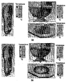
- FIG. 2A is a thermal analysis temperature showing a heat distribution state in which an air congestion zone formed in a skirt and a sliding base is heated at a high temperature (up to 131 ° C.) due to high heat generated during operation of a reactor in a lower structure of a conventional reactor steam generator. It is a distribution chart.
- Figure 2b is a thermal analysis temperature distribution diagram showing the heat distribution state that the temperature of the air congestion zone formed in the skirt and the sliding base in accordance with the present invention 40% or more lower than in the prior art.
- FIG 3 is an enlarged partial cutaway view showing a structure in which a stud bolt having a vertical through hole according to the present invention is mounted to a lower structure of a reactor steam generator.
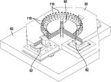
- Figure 4 is a longitudinal cross-sectional view of the lower structure of a reactor steam generator equipped with a stud bolt having a vertical through hole and a through hole according to the present invention, and having a plurality of air circulation / cooling passages.
- FIG. 5 is an explanatory view showing a detailed structure of a stud bolt having a vertical through hole and a plurality of through holes according to the present invention.
- FIG. 6 is a plan sectional view showing a structure in which a vertical through hole and a plurality of through holes according to the present invention form an air circulation / cooling passage.
- FIG. 7 is a longitudinal sectional view of a lower structure cooling apparatus of a nuclear reactor steam generator with a plurality of air circulation / cooling passages in accordance with the present invention.
- the lower structure cooling apparatus 100 of the reactor steam generator according to the present invention as shown in Figures 3 and 4, a plurality of fixing the skirt 20 of the reactor steam generator (1) to the sliding base (30). It includes a vertical through-hole 112 in the form of a venturi tube formed in the center of the stud bolt 110.
- a plurality of such stud bolts 110 are disposed around a skirt 20 of a steam generator 1 of a nuclear reactor, each having a vertical through hole 112 formed at the center thereof. .
- the vertical through hole 112 is formed in the inner flow passage similar to the venturi tube, the flow path forms a narrow neck 112a, such a neck 112a is formed of a length of approximately 30mm In addition, the flow rate of air flowing therein is increased, and the pressure is reduced.
- an air discharge pipe (not shown) extending from a fan may be additionally connected to an upper side of the vertical through hole 112 of the stud bolt 110 to perform air circulation in a forced ventilation method.
- the present invention forms an air supply hole 122 on one side of the skirt flange 22 so that each stud bolt 110 is extended to the bolt hole of the skirt 20 to be fitted.
- each stud bolt 110 is formed to include a plurality of through holes 114 in communication with the vertical through hole 112, as shown in the cross section A-A in FIG.
- the plurality of through holes 114 may be formed to be inclined.
- Each of the through holes 114 may be formed, for example, at an angle of inclination ⁇ 1 of approximately 30 degrees in the vertical direction, and the heights thereof are different in the vertical direction.
- the through hole 114 is inclined toward the vertical through hole 112 from the outer circumferential surface of the stud bolt 110 to form an inclination of approximately 30 degrees inclination angle ⁇ 1, the depth of which is gradually lowered.
- the heights are formed differently in the vertical direction with respect to each other.
- the through holes 114 have a vertical height such that their ends form a 15 mm step h in the vertical direction in the neck portion 112a of the vertical through hole 112. Form a difference.
- the through holes 114 are formed at an angle of inclination ⁇ 1 of approximately 30 degrees, respectively, and form a step h of approximately 15 mm in their heights differently in the vertical direction, the through holes 114 are formed in the structure of the horizontally formed through holes.
- the strength of the stud bolt 110 can be maintained satisfactorily without weakening the cross section of the stud bolt 110.
- the empty space portion of the through hole 114 overlaps the empty space in the horizontal cross-sectional direction of the stud bolt 110 as compared with the horizontally formed through hole.
- the strength of the stud bolt 110 can be maintained satisfactorily without making the cross section of the stud bolt 110 weak.
- these through holes 114 form a spaced apart angle ⁇ 2 in the circumferential direction of the stud bolts 110 at least approximately 60 degrees with respect to each other.
- This circumferential separation angle ⁇ 2 prevents the internal hollow space of each through hole 114 from being biased from the stud bolt 110 to one side, thereby reducing local stiffness and cross-section of the stud bolt 110. Weakening can be prevented.
- the present invention provides a circular gap P between the bolt hole of the skirt 20 and the outer diameter of the stud bolt 110, the plurality of through holes 114, and the vertical through holes 112 from the air supply hole 122. Air circulation / cooling passage leading to
- the outdoor air may be naturally circulated or supplied through the air supply hole 122, and an air discharge pipe (not shown) is connected from the upper side of the vertical through hole 112 of the stud bolt 110 by a fan.
- air circulation may be performed through the stud bolt 110 by forced ventilation.
- a plurality of air circulation grooves 124 formed concave in the skirt bottom surface 24 may be formed.
- These air circulation recesses 124 are concavely cut, and have a circular gap between the bolt hole of the skirt 20 and the outer diameter of the stud bolt 110 from the air stagnation region 70 under the reactor steam generator 1. Providing air passages leading to (P) allows air circulation.
- the air congestion zone 70 under the reactor steam generator 1 Flows through a plurality of air circulation grooves 124, a circular gap P between the bolt holes of the skirt 20 and the outer diameter of the stud bolts 110, a plurality of through holes 114 and vertical through holes 112. Forced air circulation can be achieved
- the present invention may additionally include a heat sink 140 in the upper threaded portion of the stud bolt 110.
- the heat sink 140 serves as an additional heat dissipation mechanism, and has a plurality of heat dissipation fins 142 on the outer surface of the body coupled to the upper threaded portion of the stud bolt 110. Therefore, the present invention can greatly increase the heat dissipation surface area of the stud bolt 110 through the mounting structure of the heat sink 140, and further increase the cooling effect.
- the stud bolt 110 does not suffer from heat fatigue by easily field application without entailing a large-scale replacement and reinforcement work of the nuclear power plant, and thermal deformation of the sliding base 30 does not occur. It is possible to obtain an excellent effect of greatly reducing the temperature of the air congestion zone.
- the temperature of the air congestion zone 70 formed in the skirt 20 and the sliding base 30 is reduced by about 40% compared to the conventional high heat (up to 131 °C) It was very effective.
- skirt 22 skirt flange
Landscapes
- Engineering & Computer Science (AREA)
- Physics & Mathematics (AREA)
- General Engineering & Computer Science (AREA)
- Plasma & Fusion (AREA)
- High Energy & Nuclear Physics (AREA)
- Thermal Sciences (AREA)
- Mechanical Engineering (AREA)
- Structure Of Emergency Protection For Nuclear Reactors (AREA)
- Heat-Exchange Devices With Radiators And Conduit Assemblies (AREA)
Abstract
Priority Applications (3)
| Application Number | Priority Date | Filing Date | Title |
|---|---|---|---|
| US16/078,658 US10753601B2 (en) | 2016-02-23 | 2017-02-21 | Lower structure cooling apparatus for nuclear reactor steam generator |
| EP17756779.9A EP3421884A4 (fr) | 2016-02-23 | 2017-02-21 | Appareil de refroidissement de structure inférieure pour générateur de vapeur de réacteur nucléaire |
| JP2018562487A JP2019509499A (ja) | 2016-02-23 | 2017-02-21 | 原子炉蒸気発生器向け下部構造物冷却装置 |
Applications Claiming Priority (2)
| Application Number | Priority Date | Filing Date | Title |
|---|---|---|---|
| KR1020160021202A KR101653942B1 (ko) | 2016-02-23 | 2016-02-23 | 원자로 증기 발생기의 하부 구조물 냉각장치 |
| KR10-2016-0021202 | 2016-02-23 |
Publications (1)
| Publication Number | Publication Date |
|---|---|
| WO2017146441A1 true WO2017146441A1 (fr) | 2017-08-31 |
Family
ID=56943219
Family Applications (1)
| Application Number | Title | Priority Date | Filing Date |
|---|---|---|---|
| PCT/KR2017/001895 Ceased WO2017146441A1 (fr) | 2016-02-23 | 2017-02-21 | Appareil de refroidissement de structure inférieure pour générateur de vapeur de réacteur nucléaire |
Country Status (5)
| Country | Link |
|---|---|
| US (1) | US10753601B2 (fr) |
| EP (1) | EP3421884A4 (fr) |
| JP (1) | JP2019509499A (fr) |
| KR (1) | KR101653942B1 (fr) |
| WO (1) | WO2017146441A1 (fr) |
Families Citing this family (4)
| Publication number | Priority date | Publication date | Assignee | Title |
|---|---|---|---|---|
| CN108766593B (zh) * | 2018-07-20 | 2024-08-16 | 中广核研究院有限公司 | 一种反应堆压力容器的堆内构件结构 |
| CN111140836B (zh) * | 2019-12-04 | 2021-12-07 | 深圳中广核工程设计有限公司 | 核电站蒸汽发生器套筒支撑装置及其安装方法 |
| CN111933316B (zh) * | 2020-08-12 | 2023-06-02 | 三门核电有限公司 | 一种压水堆反应堆堆腔区域高效冷却的方法 |
| KR102852693B1 (ko) * | 2024-01-24 | 2025-08-29 | 한국수력원자력 주식회사 | 증기발생기의 급수 고갈 완화를 위한 공랭식 히트파이프 냉각장치 |
Citations (5)
| Publication number | Priority date | Publication date | Assignee | Title |
|---|---|---|---|---|
| JPH02243994A (ja) * | 1990-01-10 | 1990-09-28 | Fuji Electric Co Ltd | ガス冷却型原子炉の炉心支持装置 |
| JPH05131106A (ja) * | 1991-11-11 | 1993-05-28 | Chubu Electric Power Co Inc | フイルタ逆洗装置 |
| JPH0720239U (ja) * | 1993-09-14 | 1995-04-11 | エンシュウ株式会社 | 送りねじの熱変位抑制装置 |
| JPH10227888A (ja) * | 1997-02-17 | 1998-08-25 | Mitsubishi Heavy Ind Ltd | スタッドボルト取扱装置 |
| KR19980053115U (ko) * | 1996-12-31 | 1998-10-07 | 라제훈 | 현금 및 수표 자동지급기용 잼 자동제거장치 |
Family Cites Families (11)
| Publication number | Priority date | Publication date | Assignee | Title |
|---|---|---|---|---|
| US3549493A (en) * | 1969-01-22 | 1970-12-22 | Atomic Energy Commission | Fast sodium-cooled reactor core structure |
| US3851626A (en) * | 1972-10-05 | 1974-12-03 | Westinghouse Electric Corp | Support for a steam generator |
| US3979866A (en) * | 1973-10-23 | 1976-09-14 | Nuclear Power Co. (Whetstone) Limited | Nuclear reactors |
| FR2422228A1 (fr) * | 1978-04-07 | 1979-11-02 | Commissariat Energie Atomique | Perfectionnement aux structures de calorifugeage de surfaces dans un reacteur nucleaire, notamment du genre a neutrons rapides |
| US4654188A (en) * | 1985-01-11 | 1987-03-31 | Westinghouse Electric Corp. | Pivotably mounted reactor shroud shield and shielding method |
| US5930320A (en) * | 1997-05-01 | 1999-07-27 | General Electric Company | Assemblies and methods for mitigating effects of reactor pressure vessel expansion |
| US6888909B2 (en) * | 2002-05-03 | 2005-05-03 | Westinghouse Electric Company Llc | Reactor pressure vessel |
| FR2841367B1 (fr) * | 2002-06-11 | 2005-03-18 | Framatome Anp | Dispositif de positionnement et d'alignement axial d'un assemblage de combustible et procede et dispositif de reconstitution d'un element de positionnement |
| DE102005037589B4 (de) * | 2005-08-05 | 2009-02-05 | Areva Np Gmbh | Abdeckelement für den Reaktorkern einer kerntechnischen Anlage sowie Kernreaktor |
| US9875817B2 (en) * | 2014-06-09 | 2018-01-23 | Bwxt Mpower, Inc. | Nuclear reactor support and seismic restraint with in-vessel core retention cooling features |
| KR101744318B1 (ko) * | 2016-07-27 | 2017-06-07 | 한국전력기술 주식회사 | 관류식 증기발생기 외부 일체화 소형 모듈화 원자로 |
-
2016
- 2016-02-23 KR KR1020160021202A patent/KR101653942B1/ko active Active
-
2017
- 2017-02-21 JP JP2018562487A patent/JP2019509499A/ja active Pending
- 2017-02-21 WO PCT/KR2017/001895 patent/WO2017146441A1/fr not_active Ceased
- 2017-02-21 US US16/078,658 patent/US10753601B2/en active Active
- 2017-02-21 EP EP17756779.9A patent/EP3421884A4/fr not_active Withdrawn
Patent Citations (5)
| Publication number | Priority date | Publication date | Assignee | Title |
|---|---|---|---|---|
| JPH02243994A (ja) * | 1990-01-10 | 1990-09-28 | Fuji Electric Co Ltd | ガス冷却型原子炉の炉心支持装置 |
| JPH05131106A (ja) * | 1991-11-11 | 1993-05-28 | Chubu Electric Power Co Inc | フイルタ逆洗装置 |
| JPH0720239U (ja) * | 1993-09-14 | 1995-04-11 | エンシュウ株式会社 | 送りねじの熱変位抑制装置 |
| KR19980053115U (ko) * | 1996-12-31 | 1998-10-07 | 라제훈 | 현금 및 수표 자동지급기용 잼 자동제거장치 |
| JPH10227888A (ja) * | 1997-02-17 | 1998-08-25 | Mitsubishi Heavy Ind Ltd | スタッドボルト取扱装置 |
Non-Patent Citations (1)
| Title |
|---|
| See also references of EP3421884A4 * |
Also Published As
| Publication number | Publication date |
|---|---|
| US10753601B2 (en) | 2020-08-25 |
| KR101653942B1 (ko) | 2016-09-02 |
| US20190049105A1 (en) | 2019-02-14 |
| EP3421884A1 (fr) | 2019-01-02 |
| JP2019509499A (ja) | 2019-04-04 |
| EP3421884A4 (fr) | 2019-10-16 |
Similar Documents
| Publication | Publication Date | Title |
|---|---|---|
| WO2017146441A1 (fr) | Appareil de refroidissement de structure inférieure pour générateur de vapeur de réacteur nucléaire | |
| JPH08160179A (ja) | 液体金属冷却式原子炉 | |
| WO2017099457A1 (fr) | Procédé de construction de générateur de vapeur de réacteur à eau légère sous pression de type à deux boucles et système de déplacement inverse pour celui-ci pour construction de tuyau de réacteur | |
| US12205728B2 (en) | Nuclear reactor facility integrated with passive air cooling system | |
| WO2016122106A1 (fr) | Dispositif de circulation d'air situé sous un générateur de vapeur de réacteur nucléaire | |
| CN103871487A (zh) | 一种用于高温气冷堆的石墨导向管 | |
| WO2025161397A1 (fr) | Structure de tête de réacteur et système de tête | |
| WO2018052219A1 (fr) | Procédé d'analyse de conception utilisant une analyse pour empêcher une contrainte thermique et une déformation thermique d'une structure de support inférieure de générateur de vapeur d'être limitées pendant un fonctionnement normal | |
| WO2016122104A1 (fr) | Structure de montage de matériau d'isolation thermique d'un générateur de vapeur d'un réacteur à eau légère sous pression à deux boucles | |
| US4705662A (en) | Fast neutron nuclear reactor with a steam generator integrated into the vessel | |
| WO2016122103A1 (fr) | Dispositif à plaque d'admission d'air externe sous un générateur de vapeur d'un réacteur à eau légère sous pression | |
| CN108666884A (zh) | 一种预制舱内二次设备机架 | |
| KR20170133895A (ko) | 가압경수로형 원자로 증기 발생기의 공기정체구역 공기 순환 냉각 장치 | |
| KR101613814B1 (ko) | 2루프 가압경수로형 증기 발생기의 교체 방법 | |
| KR20200083342A (ko) | 매립형 냉각배관을 통한 공냉식 콘크리트 냉각장치 | |
| JPH0357999A (ja) | 高温原子炉 | |
| WO2022092863A1 (fr) | Appareil pour empêcher une déformation par soudage et procédé de soudage de tuyau et bride l'utilisant | |
| WO2023231222A1 (fr) | Ensemble transformateur de traction | |
| CN223649712U (zh) | 一种转炉余热锅炉用气化冷却烟道 | |
| JPS6145990A (ja) | ガス冷却高温原子炉 | |
| CN108062154B (zh) | 一种计算机散热装置 | |
| Song et al. | Design, fabrication and assembly of EAST plasma facing components | |
| CN121408847B (zh) | 一种外辐射加热的蓄热承压一体化电加热装置 | |
| CN118463663B (zh) | 一种隔热型导流筒装置 | |
| CN221992376U (zh) | 一种用于真空炉的加热带固定装置 |
Legal Events
| Date | Code | Title | Description |
|---|---|---|---|
| ENP | Entry into the national phase |
Ref document number: 2018562487 Country of ref document: JP Kind code of ref document: A |
|
| NENP | Non-entry into the national phase |
Ref country code: DE |
|
| WWE | Wipo information: entry into national phase |
Ref document number: 2017756779 Country of ref document: EP |
|
| ENP | Entry into the national phase |
Ref document number: 2017756779 Country of ref document: EP Effective date: 20180924 |
|
| 121 | Ep: the epo has been informed by wipo that ep was designated in this application |
Ref document number: 17756779 Country of ref document: EP Kind code of ref document: A1 |