EP3421959B1 - Capteur de force multiaxiale, procédé de fabrication du capteur de force multiaxiale et procédé de fonctionnement du capteur de force multiaxiale - Google Patents
Capteur de force multiaxiale, procédé de fabrication du capteur de force multiaxiale et procédé de fonctionnement du capteur de force multiaxiale Download PDFInfo
- Publication number
- EP3421959B1 EP3421959B1 EP18178963.7A EP18178963A EP3421959B1 EP 3421959 B1 EP3421959 B1 EP 3421959B1 EP 18178963 A EP18178963 A EP 18178963A EP 3421959 B1 EP3421959 B1 EP 3421959B1
- Authority
- EP
- European Patent Office
- Prior art keywords
- piezoresistive
- axis
- trenches
- pair
- parallel
- Prior art date
- Legal status (The legal status is an assumption and is not a legal conclusion. Google has not performed a legal analysis and makes no representation as to the accuracy of the status listed.)
- Active
Links
Images




Classifications
-
- G—PHYSICS
- G01—MEASURING; TESTING
- G01L—MEASURING FORCE, STRESS, TORQUE, WORK, MECHANICAL POWER, MECHANICAL EFFICIENCY, OR FLUID PRESSURE
- G01L1/00—Measuring force or stress, in general
- G01L1/18—Measuring force or stress, in general using properties of piezo-resistive materials, i.e. materials of which the ohmic resistance varies according to changes in magnitude or direction of force applied to the material
-
- G—PHYSICS
- G01—MEASURING; TESTING
- G01L—MEASURING FORCE, STRESS, TORQUE, WORK, MECHANICAL POWER, MECHANICAL EFFICIENCY, OR FLUID PRESSURE
- G01L1/00—Measuring force or stress, in general
- G01L1/20—Measuring force or stress, in general by measuring variations in ohmic resistance of solid materials or of electrically-conductive fluids; by making use of electrokinetic cells, i.e. liquid-containing cells wherein an electrical potential is produced or varied upon the application of stress
- G01L1/22—Measuring force or stress, in general by measuring variations in ohmic resistance of solid materials or of electrically-conductive fluids; by making use of electrokinetic cells, i.e. liquid-containing cells wherein an electrical potential is produced or varied upon the application of stress using resistance strain gauges
- G01L1/2206—Special supports with preselected places to mount the resistance strain gauges; Mounting of supports
-
- G—PHYSICS
- G01—MEASURING; TESTING
- G01L—MEASURING FORCE, STRESS, TORQUE, WORK, MECHANICAL POWER, MECHANICAL EFFICIENCY, OR FLUID PRESSURE
- G01L1/00—Measuring force or stress, in general
- G01L1/20—Measuring force or stress, in general by measuring variations in ohmic resistance of solid materials or of electrically-conductive fluids; by making use of electrokinetic cells, i.e. liquid-containing cells wherein an electrical potential is produced or varied upon the application of stress
- G01L1/22—Measuring force or stress, in general by measuring variations in ohmic resistance of solid materials or of electrically-conductive fluids; by making use of electrokinetic cells, i.e. liquid-containing cells wherein an electrical potential is produced or varied upon the application of stress using resistance strain gauges
- G01L1/2287—Measuring force or stress, in general by measuring variations in ohmic resistance of solid materials or of electrically-conductive fluids; by making use of electrokinetic cells, i.e. liquid-containing cells wherein an electrical potential is produced or varied upon the application of stress using resistance strain gauges constructional details of the strain gauges
- G01L1/2293—Measuring force or stress, in general by measuring variations in ohmic resistance of solid materials or of electrically-conductive fluids; by making use of electrokinetic cells, i.e. liquid-containing cells wherein an electrical potential is produced or varied upon the application of stress using resistance strain gauges constructional details of the strain gauges of the semi-conductor type
-
- G—PHYSICS
- G01—MEASURING; TESTING
- G01L—MEASURING FORCE, STRESS, TORQUE, WORK, MECHANICAL POWER, MECHANICAL EFFICIENCY, OR FLUID PRESSURE
- G01L1/00—Measuring force or stress, in general
- G01L1/26—Auxiliary measures taken, or devices used, in connection with the measurement of force, e.g. for preventing influence of transverse components of force, for preventing overload
-
- G—PHYSICS
- G01—MEASURING; TESTING
- G01L—MEASURING FORCE, STRESS, TORQUE, WORK, MECHANICAL POWER, MECHANICAL EFFICIENCY, OR FLUID PRESSURE
- G01L5/00—Apparatus for, or methods of, measuring force, work, mechanical power, or torque, specially adapted for specific purposes
- G01L5/16—Apparatus for, or methods of, measuring force, work, mechanical power, or torque, specially adapted for specific purposes for measuring several components of force
- G01L5/161—Apparatus for, or methods of, measuring force, work, mechanical power, or torque, specially adapted for specific purposes for measuring several components of force using variations in ohmic resistance
- G01L5/162—Apparatus for, or methods of, measuring force, work, mechanical power, or torque, specially adapted for specific purposes for measuring several components of force using variations in ohmic resistance of piezoresistors
-
- H—ELECTRICITY
- H10—SEMICONDUCTOR DEVICES; ELECTRIC SOLID-STATE DEVICES NOT OTHERWISE PROVIDED FOR
- H10N—ELECTRIC SOLID-STATE DEVICES NOT OTHERWISE PROVIDED FOR
- H10N30/00—Piezoelectric or electrostrictive devices
- H10N30/01—Manufacture or treatment
- H10N30/03—Assembling devices that include piezoelectric or electrostrictive parts
Definitions
- the present invention relates to a microelectromechanical transducer, a method of manufacturing the microelectromechanical transducer, and a method for operating the microelectromechanical transducer.
- integrated force sensors can be manufactured with micromachining techniques. These sensors typically comprise a thin membrane, or diaphragm, suspended over a cavity provided in a silicon body. Formed within the membrane are piezoresistive elements connected together to form a Wheatstone bridge. When subjected to a force, the membrane undergoes deformation, causing a variation of resistance of the piezoresistive elements, and thus an unbalancing of the Wheatstone bridge.
- capacitive sensors are available, where the membrane provides a first plate of a capacitor, whereas a second plate is provided by a fixed reference. During use, deflection of the membrane generates a variation of the capacitance of the capacitor, which may be detected and associated to the pressure exerted on the membrane.
- piezoresistors are formed at a surface of a N-type silicon body, e.g. by means of P+ implants.
- typical semiconductor force sensors are designed to measure normal forces or shear forces, but not a combination of both.
- Multi-axial force sensors have been implemented exploiting other technologies, such as metallic load cells and ceramic load cells.
- multi-axial force sensors based on metallic load cells have issues related to high cost, big size (especially for high-load applications) and high energy requirements (caused by the use of metallic strain gauges).
- Multi-axial force sensors based on ceramic load cells have other drawbacks, related to the formation of trenches in a passivation layer; without any protection cap, the sensitive part is exposed to the environment, causing damages or leakage. For this reason, multi-axial force sensors based on ceramic load cells need a complex package, increasing their cost.
- force sensors based on ceramic load cells have typically low resolution for high full scale ranges.
- Patent document EP1653208 relates to a multi-axis force sensor chip and a multi-axis force sensor using the same.
- the multi-axis force sensor comprises a structural body for transferring the forces to the sensor chip.
- the sensor chip comprises a substrate, with 4 pairs of parallel trenches machined in the substrate. Stresses generated by the forces are concentrated on the bridges between the trenches. 3 piezoresistors are attached to each bridge and form a Wheatstone bridge circuit with a further piezoelectric element, which is placed in an area not influenced by the stresses and provides for temperature compensation.
- Patent document JP2010185781 provides a piezoresistive element type acceleration sensor which is stable electrically and mechanically and suitable for being made compact.
- Patent document US2003/209075 relates to an acceleration sensor and a manufacturing method for the same, and more specifically, a mass production type acceleration sensor to be used for small-sized household electronic devices and a manufacturing method for the same.
- Patent document US2010/300205 relates to a semiconductor acceleration sensor for detection of acceleration, which is used in automobiles, aircraft, portable terminal equipment, and toys.
- Patent document US2006/272413 relates to semiconductor devices, MEMS, sensors and more specifically to 3D three-axis accelerometers, vibration sensors and inclinometers for consumer and other applications.
- the aim of the present invention is to provide a microelectromechanical transducer, a method of manufacturing the microelectromechanical transducer, and a method for operating the microelectromechanical transducer to overcome the problems previously illustrated.
- one of the aims of the present invention is to provide a semiconductor microelectromechanical transducer based on piezoresistive transduction, configured to work both as a uni-axial force sensor or a multi-axial force sensor.
- a microelectromechanical transducer a method of manufacturing the microelectromechanical transducer, and a method for operating the microelectromechanical transducer are provided, as defined in the annexed claims.
- Figures 1A , 1B show respective cross-section views of a microelectromechanical transducer, in particular a multi-axial force sensor, 1 according to an embodiment of the present invention.
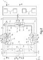
- Figure 2 shows a top view of the multi-axial force sensor 1 of figures 1A , 1B on a xy-plane.
- the multi-axial force sensor 1 in figures 1A , 1B and 2 is represented in a system of spatial coordinates defined by three axes x, y, z, orthogonal to one another; the cross-section view of figure 1A is taken along the line I-I shown in figure 2 , while the cross-section view of figure 1B is taken along the line II-II shown in figure 2 .
- the multi-axial force sensor 1 comprises a sensor body 2 having a front surface 2a and rear surface 2b, extending in parallel with the plane xy.
- a plurality of trenches 4 extends throughout the sensor body 2 from the front surface 2a to the rear surface 2b, in particular parallel to the z axis.
- the plurality of trenches 4 includes first trenches 4a and second trenches 4b.
- the first trenches 4a have a main direction of extension, parallel to the plane xy, parallel to a first direction.
- the second trenches 4b have a main direction of extension, parallel to the plane xy, parallel to a second direction, different from the first direction.
- the main direction of extension, on the plane xy, of the first trenches 4a is the x axis
- the main direction of extension on the plane xy of the second trenches 4b is the y axis. Therefore, according to the embodiment of figures 1A , 1B and 2 , the first direction of the first trenches 4a is orthogonal to the second direction of the second trenches 4b.
- a plurality of piezoresistive groups 6a-6b is arranged at the front surface 2a of the substrate 2; in particular, each first piezoresistive group 6a is arranged between a respective pair of first trenches 4a, whereas each second piezoresistive group 6b is arranged between a respective pair of second trenches 4b; each of the first piezoresistive groups 6a and the second piezoresistive groups 6b include piezoresistive elements 19a-19d.
- each piezoresistive group 6a is arranged one next to the other along a respective direction parallel to the x axis, at a distance from each other and from the trenches 4a, whereas the piezoresistive elements 19a-19d of each piezoresistive group 6b are arranged one next to the other along a respective direction parallel to the y axis, at a distance from each other and from the trenches 4b.
- the trenches 4 and the piezoresistive groups 6a-6b define an active region 7 of the multi-axial force sensor 1.
- the sensor body 2 is of a semiconductor material and in particular silicon; more specifically, the sensor body 2 is made of n-type single-crystal (100) silicon and the piezoresistors 6 are p+ implanted regions.
- a first structural body 8 having the function of a cap is coupled to the front surface 2a of the sensor body 2 through a first coupling region 16.
- the first structural body 8 is only partially shown in figure 2 , covering only one piezoresistive group 6a, and exposing the other piezoresistive groups 6a-6b.
- the first structural body 8 is referenced as "cap”.
- the cap 8 has a recess 10 facing the front surface 2a in correspondence of the active region 7.
- the recess 10 is delimited by lateral walls 10a of height H, and a bottom wall 10b. Exemplary values of the height H of the lateral walls 10a are in the range of 1-500 ⁇ m.
- the lateral walls 10a and the bottom wall 10b are adjacent to one another, forming an angle ⁇ .
- the angle ⁇ is greater than or equal to 90°. In further embodiments, the angle ⁇ may be lower than 90°.
- the lateral walls 10a surround the active region 7 and the bottom wall 10b extends at a distance from the front surface 2a of the sensor body 2.
- the recess 10 of the cap 8 defines a sealed cavity, wherein the active region 7 is housed.
- the cavity is sealed by means of the first coupling region 16, made for instance of glass, metal bonding like Al/Ge or Au/Ge alloys, bi-adhesive layers, in general wafer bonding materials; the first coupling region 16 may be formed by wafer-to-wafer bonding techniques (e.g. glass frit).
- a plurality of pads 17 are arranged on a region of the sensor body 2 not covered by the cap 8, to allow electrical access to the multi-axial force sensor 1, for instance by wire bonding.
- the pads 17 form electrical contact terminals for the piezoresistive groups 19a-19d connected in the Wheatstone bridge configuration.
- the pads are connected to the piezoresistive groups 19a-19d by conductive paths passing through the cap 8 and/or the sensor body 2.
- the pads 17 may be of any suitable material, for instance Aluminium.
- a second structural body 12 having the function of a supporting element or substrate is coupled to the rear surface 2b of the sensor body 2 through a second coupling region 18.
- the second structural body 12 is referenced as "substrate”.
- the substrate 12 has a recess 14 facing the rear surface 2b in correspondence of the area in which the trenches 7 extend.
- the recess 14 is delimited by lateral walls 14a and a bottom wall 14b.
- the lateral walls 14a surround the trenches 4 and the bottom wall extends at a distance from the rear surface 2b of the sensor body 2.
- the recess 14 of the substrate 12 defines a sealed cavity.
- the recesses 14 and 10 are at least partially aligned along the z-axis.
- the recesses 14 and 10 are overlapping, as it can be seen from a top view on the xy-plane.
- the recess 14 is sealed by means of the second coupling region 18, made for instance of glass, metal bonding materials like Al/Ge alloys or bi-adhesive layers.
- the second coupling region 18 may be formed by wafer-to-wafer bonding techniques (e.g. glass frit).
- the cap 8 and the substrate 12 may be of any suitable material, such as semiconductor materials, ceramics, steel or metallic alloys (e.g. Invar, or FeNiCo alloys).
- a first sensing unit 7a includes a first piezoresistive group 6a and the respective pair of first trenches 4a between which the first piezoresistive group 6a is arranged
- a second sensing unit 7b includes a second piezoresistive group 6b and the respective pair of second trenches 4b between which the second piezoresistive group 6b is arranged.
- Two first sensing units 7a extend at a distance from one another with a respective main direction dx1, dx2 of extension parallel to the x axis.
- Two second sensing units 7b extend at a distance from one another with a respective main direction dy1, dy2 of extension parallel to the y axis.
- each first trench 4a is seamlessly connected to one respective second trench 4b; more in particular, first trenches 4a and second trenches 4b are connected at one of their ends, forming a right angle, and extend continuously from a first piezoresistive group 6a to a second piezoresistive group 6b.
- first trenches 4a of first sensing units 7a are not connected to second trenches 4b of second sensing units 7b.
- the trenches 4 have a substantially rectangular shape, for instance with rounded corners. Longer sides of the rectangles define the length of the trenches 4, whereas the shorter sides define the width W t of the trenches 4.
- Each piezoresistive element 19a-19d of the piezoresistive groups 6a-6b has a substantially rectangular or oval or elliptical shape, with a major axis defining a length L p of the piezoresistive element 19a-19d and a minor axis defining a width W p of the piezoresistive element 19a-19d.
- Exemplary values of the dimensions of the trenches 4 are in the range of 10-1000 ⁇ m for the length, and in the range of 5-500 ⁇ m for the width W t , provided that the width W t of the trench is higher than the length L p of the piezoresistive elements 19a-19d.
- each piezoresistive element 19a-19d may be arranged in such a way that their length L p is parallel or perpendicular to the length L t of the trenches 4a, 4b of the respective sensing unit 7a-7b.
- each piezoresistive group 6a-6b includes four piezoresistive elements 19a-19d, which are electrically connected in a Wheatstone bridge configuration, as schematically shown in Figure 3 .
- two piezoresistive elements 19a, 19d are arranged in such a way that their length L p is parallel to the length L t of the trenches 4a (4b) of the respective sensing unit 7a (7b), whereas the other two piezoresistors 6b, 6c, are arranged in such a way that their length L p is perpendicular to the length L t of the trenches 4a (4b) of the respective sensing unit 7a (7b).
- Figure 4 illustrates the multi-axial force sensor 1 in a working condition. More in particular, figure 4 shows the multi-axial force sensor 1, in the cross-section view of figure 1A , when subject to a multi-axial force F represented by an arrow 39.
- the force F can be expressed in terms of its components Fx, Fy, Fz, respectively along the x, y, z axes. Due to the fact that the cap 8 is anchored to the sensor body 2 through the first coupling region 16, the relative expansion of the cap 8 on the sensor body 2 caused by the applied force induces a shear load and thus a planar stress distribution at the surface 2a of the sensor body 2, and therefore on the piezoresistive units 19a-19d.
- the multi-axial force presents non-zero components along all axes x, y, z, therefore it can be considered a superposition of normal forces and out of plane forces (with respect to the surface 2a).
- the force components Fx, Fy, Fz of the multi-axial force F induce a planar mechanical stress ⁇ at the surface 2a of the sensor body 2.
- the arrangement of the trenches 4 affects the value of the components of the planar stress ⁇ in the regions where the piezoresistive groups 6a-6b are located.
- the respective trenches 4a-4b limit the effect of the force components parallel to the respective main direction of extension dx1, dx2, dy1, dy2.
- force component Fx induces a planar stress ⁇ which is maximized in the regions where the piezoresistive groups 6b are located
- force component Fy induces a planar stress ⁇ which is maximized in the regions where the piezoresistive groups 6a are located
- force component Fz induces an equal planar stress distribution on all the piezoresistive groups 6a-6b.
- ⁇ in_plane is about one half of the silicon piezoresistive coefficient ⁇ 44 ( ⁇ in_plane ⁇ 70x10 -11 Pa -1 ).
- first piezoresistive groups 6a are arranged between a pair of first trenches 4a along a direction dx1, dx2, parallel to the x axis.
- the effect of force component Fx on the planar stress ⁇ is reduced (due to the first trenches 4a), and the effect of forces Fy is increased. Therefore, the piezoresistive units 19a-19d of the first sensing units 7a are subject to a planar stress ⁇ with main component parallel to the y axis.
- ⁇ li is much higher in module than ⁇ ti ; on the contrary, since the piezoresistive units 19a and 19d of the first sensing units 7a have a main direction of extension parallel to the x axis, ⁇ ti is much higher in module than ⁇ li .
- the piezoresistive group 6a arranged along the dx1 direction is subject to a compressive stress acting along the y axis, while the piezoresistive group 6a arranged along the dx2 direction is subject to a tensile stress.
- the piezoresistive group 6a arranged along the dx1 direction is subject to a tensile stress acting along the y axis, while the piezoresistive group 6a arranged along the dx2 direction is subject to a compressive stress.
- compressive stress has a negative sign
- there is an increase of the resistance values R a , R d of the piezoresistive units 19a, 19d of the piezoresistive group 6a arranged along the dx2 direction while there is a decrease of the resistance values R b , R c of the piezoresistive units 19b, 19c of said piezoresistive group 6a.
- the force component Fy has negligible effect on the resistance values of the piezoresistive units 19a-19d of the second piezoresistive groups 6b. This is mainly due to two reasons. From a mechanical point of view, the low sensitivity of the second piezoresistive groups 6b is due to the presence of the trenches 4b and the fact that the two edges of the cap 8 in contact with the sensing units 7b are parallel to the orientation of the sensing units 7b, which is also parallel to the direction of the force component Fy.
- the output voltage Vo of the first sensing units 7a is correlated to the force component Fy parallel to the y axis, while the output voltage Vo of the second sensing units 7b is correlated to the force component Fx parallel to the x axis.
- each Wheatstone bridge output does not only depend on the type of induced stress over the corresponding zone, but it depends also on the configuration of electrical connections between the piezoresistive units 19a-19d.
- the fact that the force component Fy has negligible effect on the resistance values of the piezoresistive units 19a-19d of the second piezoresistive groups 6b is also due to the fact that the piezoresistive units 19a-19d of the second piezoresistive groups 6b are positioned symmetrically with respect to a line parallel to the x-axis and passing by the centroid of the active region 7; as a consequence, the corresponding Wheatstone bridge is insensitive with respect to loads that induce either the same stress contribution over both piezoresistive groups 6b or an opposite stress contribution for the piezoresistive units 19a and 19b in comparison to the piezoresistive units 19c and 19d.
- an n-type single-crystal (100) silicon wafer comprising the sensor body 2 is provided.
- a first photoresist mask is formed on top of the front surface 2a, by standard optical lithography techniques. Openings in the photoresist mask correspond to the regions where the piezoresistive units 19a-19d should be formed.
- the piezoresistive units 19a-19d may be formed by implantation or diffusion of p-type dopant elements, for instance boron.
- the techniques to form the piezoresistive units 19a-19d, as well as their connection in a Wheatstone bridge, are known and thus they will not be described in further detail.
- a second photoresist mask is formed on top of the front surface 2a.
- the openings in the second photoresist mask correspond to the areas in which the trenches 4 should be formed, at a distance from the areas in which the piezoresistive units 19a-19d were formed.
- the sensor body 2 is etched selectively through its whole thickness, until openings at the rear surface 2b are formed.
- the etching step to form the trenches 4 is a standard bulk micromachining technique and it may be of a wet or dry type.
- the second photoresist mask is then removed.
- a second wafer of silicon or any other suitable material comprising the cap 8.
- a third photoresist mask is formed on the front side of the second wafer by standard optical lithography techniques.
- the openings on the third photoresist mask correspond to the position of the recess 10.
- the area of the openings on the third photoresist mask should be defined in such a way that it includes the area of the openings of both the first and the second photoresist mask when they are aligned to one another.
- the cap 8 is etched selectively up to a depth lower than its thickness. Then, the third photoresist mask is removed.
- a third wafer of silicon or any other suitable material comprising the substrate 12.
- a fourth photoresist mask is formed on the front side of the third wafer by standard optical lithography techniques.
- the openings on the fourth photoresist mask correspond to the position of the cavity 14.
- the area of the openings on the fourth photoresist mask should be defined in such a way that it includes the area of the openings of both the first and the second photoresist mask when they are aligned to one another.
- the substrate 12 is etched selectively up to a depth lower than its thickness. Then, the fourth photoresist mask is removed.
- the first wafer, comprising the sensor body 2, and the second wafer, comprising the cap 8 are coupled to one another at the surface 2a through the coupling region 16, obtained by known wafer-to-wafer bonding techniques, for instance glass frit.
- the first wafer comprising the sensor body 2 and the third wafer, comprising the substrate 12, are coupled to one another at the surface 2b through the coupling region 18, obtained by known wafer-to-wafer bonding techniques, for instance glass frit.
- the active region 7 is not exposed to the environment.
- Figure 5 shows a multi-axial force sensor 20 according to a further embodiment of the present invention.
- the recesses 10 and 14 are not present. All other elements are in common to the multi-axial force sensor 1 of figures 1A , 1B , 2 , and designated by the same reference numbers, thus they are not described any further.
- the cap 8 and the substrate 12 are at a distance from the front surface 2a and rear surface 2b, respectively, by means of the coupling regions 16 and 18.
- the multi-axial force sensor 20 of figure 5 is easier to be manufactured than the multi-axial force sensor 1 of figures 1A , 1B , 2 , because it does not include the etching steps of the cap 8 and the substrate 12 to form the recesses 10 and 14.
- a pressure or force applied along the z-axis may cause the cap 8 and the substrate 12 to bend towards the sensor body 2 in correspondence of their respective free surfaces facing the sensor body 2.
- neither the cap 8 nor the substrate 12 should come into direct contact, while bending, with the piezoresistive groups 6a-6b.
- the multi-axial force sensor 20 can withstand lower forces applied to the z axis with respect to the multi-axial force sensor 1 of figures 1A , 1B , 2 since the stress concentration in the region where the cap 8 and the substrate 12 come in contact with the sensor body 2 is higher compared to the multi-axial force sensor 1).
- Figure 6 shows a multi-axial force sensor 30 according to a further embodiment of the present invention.
- the substrate 12 is not present.
- trenches 34 functionally corresponding to the trenches 4 of the multi-axial force sensor 1, extend in the sensor body 2 at a depth lower than the thickness of the sensor body 2.
- the trenches 34 end within the sensor body 2, at a distance from the rear surface 2b. Exemplary values of the depth of the trenches 34 range from 5 to 100 ⁇ m.
- the trenches 34 of the multi-axial force sensor 30 include first trenches 34a having main direction of extension parallel to the x axis and second trenches 34b having main direction of extension parallel to the y axis, analogously respectively to the first trenches 4a and the second trenches 4b of the multi-axial force sensor 1 of figures 1A , 1B , 2 . All other elements are in common to the multi-axial force sensor 1 of figures 1A , 1B , 2 and designated by the same reference numbers, thus they are not described any further.
- the multi-axial force sensor 30 has a lower thickness and lower manufacturing cost than the multi-axial force sensors 1 and 20.
- the recess 10 of the cap 8 of the multi-axial force sensor 30 may not be present, analogously to what described above with reference to Figure 5 .
- FIG. 7 shows a top view of a multi-axial force sensor 40 according to a further embodiment of the present invention.
- the multi-axial force sensor 40 includes two first sensing units 47a and two second sensing units 47b.
- Each first sensing unit 47a includes two first trenches 4a and one first piezoresistive group 6a.
- Each second sensing unit 47b includes two second trenches 4b and one first piezoresistive group 6a.
- Each first trench 4a has a main direction of extension parallel to the x axis.
- a first piezoresistive group 6a extends between respective first trenches 4a, along a direction parallel to the main direction of extension of the first trenches 4a and at a distance from the first trenches 4a. Therefore, for each first sensing unit 47a, the first piezoresistive group 6a extends along a main direction dx1, respectively dx2, parallel to the x axis and two first trenches 4a extend along respective main directions which are parallel to, and distinct from, the main direction dx1 (dx2).
- the piezoresistive group 6a and the trenches 4a of a same first sensing unit 47a are aligned to one another along the y axis. More in particular, both first sensing units 47a are aligned to one another along the y axis and are symmetric with respect to a line parallel to the x axis and passing by the centroid of the active region 7.
- a second piezoresistive group 6b extends between respective second trenches 4b, along a direction parallel to the main extension of the second trenches 4b, and at a distance from the second trenches 4b. Therefore, for each second sensing unit 47b, the second piezoresistive group 6b extends along a main direction dy1, respectively dy2, parallel to the y axis and two second trenches 4b extend along respective directions which are parallel to, and distinct from, the main direction dy1 (dy2) .
- the piezoresistive group 6b and the trenches 4b of a same second sensing unit 47b are aligned to one another along the x axis. More in particular, both second sensing units 47b are aligned to one another along the x axis and are symmetric with respect to a line parallel to the y axis and passing by the centroid of the active region 7.
- the first sensing units 47a do not overlap with the second sensing units 47b.
- a shear force component Fy parallel to the y axis will induce a tensile planar stress ⁇ x parallel to the x axis on the first piezoresistive groups 6a, while a shear force component Fx parallel to the x axis will induce a tensile planar stress ⁇ y parallel to the y axis on the second piezoresistive groups 6b.
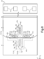
- Figure 8 shows a top view of a multi-axial force sensor 50 according to a further embodiment of the present invention.
- the multi-axial force sensor 50 includes two first sensing units 47a and two second sensing units 47b, which are elements in common to the multi-axial force sensor 40 of figure 7 .
- the main directions dx1, dx2 of extension of the first piezoresistive groups 6a are coincident with one another and with the x axis; analogously, also the main directions dy1, dy2 of extension of the second piezoresistive groups 6b are coincident with one another and with the y axis.
- the main directions dx, dy of extension of the sensing units 47a-47b are chosen in a way such that the sensing units 47a-47b are arranged in the shape of a cross; moreover, the main directions dx, dy of extension of the sensing units 47a-47b are chosen in order to seamlessly connect a first trench 4a of a first sensing unit 47a to a respective second trench 4b of a second sensing unit 47b, and the other first trench 4a of said first sensing unit 47a to a respective second trench 4b of the other second sensing unit 47b.
- the spatial configuration of the trenches 4 and the piezoresistive units 19a-19d allows to obtain a multi-axial force sensor based on silicon technology, able to measure both normal forces and out-of-plane shear forces.
- the spatial configuration of the trenches 4 and the piezoresistive units 19a-19d allows to have accurate measurements in case of non-homogenous or partially concentrated loads.
- the cap 8, the sensor body 2 and the substrate 12 may be of any suitable size and shape.
- the piezoresistive groups 6a, 6b may include only one or two piezoresistive elements.
- the trenches may have different shapes than the rectangular, or substantially rectangular, shape described above.
- the trenches may have a rounded shape, a generic polygonal shape, etc.
- the main directions of extension of the first and second trenches may also be non-ortoghonal to one another, i.e. the main directions of extension of the first and second trenches intersect to one another forming an angle different from 90 degrees.
- the size of the cap and of the active region can be enlarged in order to increase the full scale of the multi-axial force sensor, according to the needs of the application.
Landscapes
- Physics & Mathematics (AREA)
- General Physics & Mathematics (AREA)
- Engineering & Computer Science (AREA)
- Manufacturing & Machinery (AREA)
- Pressure Sensors (AREA)
- Measuring Fluid Pressure (AREA)
- Force Measurement Appropriate To Specific Purposes (AREA)
Claims (13)
- Transducteur microélectromécanique (1 ; 20 ; 30 ; 40 ; 50) configuré pour mesurer des forces, comprenant :- un corps de semi-conducteur (2), ayant une première surface (2a) et une deuxième surface (2b) opposées l'une à l'autre et parallèles à un plan horizontal (xy) formé par un premier axe (x ; y) et un deuxième axe (y ; x) orthogonaux entre eux ;- une pluralité de tranchées (4) s'étendant dans le corps de semi-conducteur (2) de la première surface (2a) vers la deuxième surface (2b), comportant : une première paire de tranchées (4a) ayant sur ledit plan horizontal (xy) une direction principale d'extension respective le long du premier axe (x ; y), une deuxième paire de tranchées (4b) ayant sur ledit plan horizontal (xy) une direction principale d'extension respective le long du deuxième axe (y ; x) différente du premier axe (x ; y) et formant un angle avec celui-ci, une troisième paire de tranchées (4a) substantiellement parallèles entre elles et à la première paire de tranchées, et une quatrième paire de tranchées (4b) substantiellement parallèles entre elles et à la deuxième paire de tranchées ;- un premier capteur piézorésistif (6a) et un deuxième capteur piézorésistif (6b) s'étendant au niveau de la première surface (2a) du corps de semi-conducteur (2), placés respectivement entre lesdites première et deuxième paires de tranchées (4a, 4b) ;
un troisième capteur piézorésistif (6a) et un quatrième capteur piézorésistif (6b) s'étendant au niveau de la première surface (2a) du corps de semi-conducteur (2), placés respectivement entre lesdites troisième et quatrième paires de tranchées (4a, 4b),
dans lequel chacun des premier (6a), deuxième (6b), troisième (6a) et quatrième (6b) capteurs piézorésistifs (6a, 6b) comprend quatre éléments piézorésistifs (19a-19d) montés de façon à former un pont de Wheatstone respectif, et dans lequel le premier capteur piézorésistif (6a), le deuxième capteur piézorésistif (6b), le troisième capteur piézorésistif (6a), le quatrième capteur piézorésistif (6b) et la pluralité de tranchées (4) forment une région active (7a, 7b) du transducteur microélectromécanique ;- un premier corps structurel (8), relié mécaniquement à la première surface (2a) du corps de semi-conducteur (2) de manière à former une première cavité hermétique (10) qui renferme la région active (7a, 7b),
dans lequel :chacun des premier et deuxième capteurs piézorésistifs (6a, 6b) comprend au moins deux éléments piézorésistifs (19a-19d) ;les éléments piézorésistifs (19a-19d) du premier capteur piézorésistif (6a) sont placés l'un à côté de l'autre le long d'une direction respective parallèle au premier axe (x ; y), à distance l'un de l'autre et par rapport à la première paire de tranchées (4a), et comprennent une première unité piézorésistive (19a ; 19d) ayant une direction principale d'extension parallèle au premier axe (x ; y) et une deuxième unité piézorésistive (19b ; 19c) ayant une direction principale d'extension parallèle au deuxième axe (y ; x) ;les éléments piézorésistifs (19a-19d) du deuxième capteur piézorésistif (6b) sont placés l'un à côté de l'autre le long d'une direction respective parallèle au deuxième axe (y ; x), à distance l'un de l'autre et par rapport à la deuxième paire de tranchées (4b), et comprennent une troisième unité piézorésistive (19b ; 19c) ayant une direction principale d'extension parallèle au premier axe (x ; y) et une quatrième unité piézorésistive (19a ; 19d) ayant une direction principale d'extension parallèle au deuxième axe (y ; x) ;les éléments piézorésistifs (19a-19d) du troisième capteur piézorésistif (6a) sont placés l'un à côté de l'autre le long d'une direction respective parallèle au premier axe (x ; y), à distance l'un de l'autre et par rapport à la troisième paire de tranchées (4a), et comprennent une cinquième unité piézorésistive (19a ; 19d) ayant une direction principale d'extension parallèle au premier axe (x ; y) et une sixième unité piézorésistive (19b ; 19c) ayant une direction principale d'extension parallèle au deuxième axe (y ; x) ;les éléments piézorésistifs (19a-19d) du quatrième capteur piézorésistif (6b) sont placés l'un à côté de l'autre le long d'une direction respective parallèle au deuxième axe (y ; x), à distance l'un de l'autre et par rapport à la quatrième paire de tranchées (4b), et comprennent une septième unité piézorésistive (19b ; 19c) ayant une direction principale d'extension parallèle au premier axe (x ; y) et une huitième unité piézorésistive (19a ; 19d) ayant une direction principale d'extension parallèle au deuxième axe (y ; x) ;et dans lequel :les premier et troisième capteurs piézorésistifs (6a) sont symétriques par rapport à un premier axe de symétrie parallèle au premier axe (x) et passant par un centroïde de la première cavité hermétique (10), de sorte que, lorsqu'une force est appliquée au premier corps structurel (8), des composantes de force positive et négative sont générées au niveau de la première surface (2a) du corps de semi-conducteur (2) le long des côtés positif et respectivement négatif du deuxième axe (y), dans lequel les composantes de force positive le long du deuxième axe (y) créent une contrainte de compression plane (σ) sur le premier capteur piézorésistif (6a) et une contrainte de traction plane (σ) sur le troisième capteur piézorésistif (6a), tandis que les composantes de force négative le long du deuxième axe (y) créent une contrainte de traction plane (σ) sur le premier capteur piézorésistif (6a) et une contrainte de compression plane (σ) sur le troisième capteur piézorésistif (6a) ; etles deuxième et quatrième capteurs piézorésistifs (6b) sont symétriques par rapport à un deuxième axe de symétrie parallèle au deuxième axe (y) et passant par le centroïde de la première cavité hermétique (10), de sorte que, lorsque ladite force est appliquée au premier corps structurel (8), des composantes de force positive et négative sont générées au niveau de la première surface (2a) du corps de semi-conducteur (2) le long des côtés positif et respectivement négatif du premier axe (x), dans lequel les composantes de force positive le long du premier axe (x) créent une contrainte de compression plane (σ) sur le deuxième capteur piézorésistif (6b) et une contrainte de traction plane (σ) sur le quatrième capteur piézorésistif (6b), tandis que les composantes de force négative appliquées le long du premier axe (x) créent une contrainte de traction plane (σ) sur le deuxième capteur piézorésistif (6b) et une contrainte de compression plane (σ) sur le quatrième capteur piézorésistif (6b). - Transducteur microélectromécanique (1 ; 20 ; 30 ; 40 ; 50) configuré pour mesurer des forces, comprenant :- un corps de semi-conducteur (2), ayant une première surface (2a) et une deuxième surface (2b) opposées l'une à l'autre et parallèles à un plan horizontal (xy) formé par un premier axe (x ; y) et un deuxième axe (y ; x) orthogonaux entre eux ;- une pluralité de tranchées (4) s'étendant dans le corps de semi-conducteur (2) de la première surface (2a) vers la deuxième surface (2b), comportant : une première paire de tranchées (4a) ayant sur ledit plan horizontal (xy) une direction principale d'extension respective le long du premier axe (x ; y), une deuxième paire de tranchées (4b) ayant sur ledit plan horizontal (xy) une direction principale d'extension respective le long du deuxième axe (y ; x) différente du premier axe (x ; y) et formant un angle avec celui-ci, une troisième paire de tranchées (4a) substantiellement parallèles entre elles et à la première paire de tranchées, et une quatrième paire de tranchées (4b) substantiellement parallèles entre elles et à la deuxième paire de tranchées ;- un premier capteur piézorésistif (6a) et un deuxième capteur piézorésistif (6b) s'étendant au niveau de la première surface (2a) du corps de semi-conducteur (2), placés respectivement entre lesdites première et deuxième paires de tranchées (4a, 4b) ;
un troisième capteur piézorésistif (6a) et un quatrième capteur piézorésistif (6b) s'étendant au niveau de la première surface (2a) du corps de semi-conducteur (2), placés respectivement entre lesdites troisième et quatrième paires de tranchées (4a, 4b),
dans lequel chacun des premier (6a), deuxième (6b), troisième (6a) et quatrième (6b) capteurs piézorésistifs (6a, 6b) comprend quatre éléments piézorésistifs (19a-19d) montés de façon à former un pont de Wheatstone respectif, et dans lequel le premier capteur piézorésistif (6a), le deuxième capteur piézorésistif (6b), le troisième capteur piézorésistif (6a), le quatrième capteur piézorésistif (6b) et la pluralité de tranchées (4) forment une région active (7a, 7b) du transducteur microélectromécanique ;- un premier corps structurel (8), relié mécaniquement à la première surface (2a) du corps de semi-conducteur (2) de manière à former une première cavité hermétique (10) qui renferme la région active (7a, 7b),
dans lequel :chacun des premier et deuxième capteurs piézorésistifs (6a, 6b) comprend au moins deux éléments piézorésistifs (19a-19d) ;dans lequel les éléments piézorésistifs (19a-19d) du premier capteur piézorésistif (6a) sont placés l'un à côté de l'autre le long d'une direction respective parallèle au premier axe (x ; y), à distance l'un de l'autre et par rapport à la première paire de tranchées (4a), et comprennent une première unité piézorésistive (19a ; 19d) ayant une direction principale d'extension parallèle au premier axe (x ; y) et une deuxième unité piézorésistive (19b ; 19c) ayant une direction principale d'extension parallèle au deuxième axe (y ; x) ;les éléments piézorésistifs (19a-19d) du deuxième capteur piézorésistif (6b) sont placés l'un à côté de l'autre le long d'une direction respective parallèle au deuxième axe (y ; x), à distance l'un de l'autre et par rapport à la deuxième paire de tranchées (4b), et comprennent une troisième unité piézorésistive (19b ; 19c) ayant une direction principale d'extension parallèle au premier axe (x ; y) et une quatrième unité piézorésistive (19a ; 19d) ayant une direction principale d'extension parallèle au deuxième axe (y ; x) ;les éléments piézorésistifs (19a-19d) du troisième capteur piézorésistif (6a) sont placés l'un à côté de l'autre le long d'une direction respective parallèle au premier axe (x ; y), à distance l'un de l'autre et par rapport à la troisième paire de tranchées (4a), et comprennent une cinquième unité piézorésistive (19a ; 19d) ayant une direction principale d'extension parallèle au premier axe (x ; y) et une sixième unité piézorésistive (19b ; 19c) ayant une direction principale d'extension parallèle au deuxième axe (y ; x) ;les éléments piézorésistifs (19a-19d) du quatrième capteur piézorésistif (6b) sont placés l'un à côté de l'autre le long d'une direction respective parallèle au deuxième axe (y ; x), à distance l'un de l'autre et par rapport à la quatrième paire de tranchées (4b), et comprennent une septième unité piézorésistive (19b ; 19c) ayant une direction principale d'extension parallèle au premier axe (x ; y) et une huitième unité piézorésistive (19a ; 19d) ayant une direction principale d'extension parallèle au deuxième axe (y ; x),et dans lequel :- les premier et troisième capteurs piézorésistifs (6a) sont symétriques par rapport à un premier axe de symétrie orthogonal au premier axe (x) et passant par un centroïde de la première cavité hermétique (10), de sorte que, lorsqu'une force est appliquée au premier corps structurel (8), des composantes de force positive et négative sont générées au niveau de la première surface (2a) du corps de semi-conducteur (2) le long des côtés positif et respectivement négatif du premier axe (x), dans lequel les composantes de force positive le long du premier axe (x) créent une contrainte de traction plane (σ) sur le premier capteur piézorésistif (6a) et une contrainte de compression plane (σ) sur le troisième capteur piézorésistif (6a), tandis que les composantes de force négative le long du premier axe (x) créent une contrainte de compression plane (σ) sur le premier capteur piézorésistif (6a) et une contrainte de traction plane (σ) sur le troisième capteur piézorésistif (6a) ;- les deuxième et quatrième capteurs piézorésistifs (6b) sont symétriques par rapport à un deuxième axe de symétrie orthogonal au deuxième axe (y) et passant par le centroïde de la première cavité hermétique (10), de sorte que, lorsqu'une force est appliquée au premier corps structurel (8), des composantes de force positive et négative sont générées au niveau de la première surface (2a) du corps de semi-conducteur (2) le long des côtés positif et respectivement négatif du deuxième axe (y), dans lequel les composantes de force positive le long du deuxième axe (y) créent une contrainte de traction plane (σ) sur le deuxième capteur piézorésistif (6b) et une contrainte de compression plane (σ) sur le quatrième capteur piézorésistif (6b), tandis que les composantes de force négative appliquées le long du deuxième axe (y) créent une contrainte de compression plane (σ) sur le deuxième capteur piézorésistif (6b) et une contrainte de traction plane (σ) sur le quatrième capteur piézorésistif (6b). - Transducteur microélectromécanique selon la revendication 1 ou 2, dans lequel :la première paire de tranchées (4a) comprend deux tranchées qui sont alignées le long de directions principales d'extension respectives qui coïncident l'une avec l'autre, le premier capteur piézorésistif (6a) étant aligné le long des directions principales d'extension coïncidentes de la première paire de tranchées (4a), etla deuxième paire de tranchées (4b) comprend deux tranchées qui sont alignées le long de directions principales d'extension respectives qui coïncident l'une avec l'autre, le deuxième capteur piézorésistif (6b) étant aligné le long des directions principales d'extension coïncidentes de la deuxième paire de tranchées (4b).
- Transducteur microélectromécanique selon l'une quelconque des revendications 1 à 2, dans lequel chacune des première et deuxième paires de tranchées (4a, 4b) comprend deux tranchées qui sont alignées le long de directions principales d'extension respectives qui sont parallèles entre elles et distinctes l'une de l'autre.
- Transducteur microélectromécanique selon la revendication 1 ou 2, dans lequel :la troisième paire de tranchées (4a) comprend deux tranchées qui sont alignées le long de directions principales d'extension respectives qui coïncident l'une avec l'autre, le troisième capteur piézorésistif (6a) étant aligné le long des directions principales d'extension coïncidentes de la troisième paire de tranchées (4a), etla quatrième paire de tranchées (4b) comprend deux tranchées qui sont alignées le long de directions principales d'extension respectives qui coïncident l'une avec l'autre, le quatrième capteur piézorésistif (6b) étant aligné le long des directions principales d'extension coïncidentes de la quatrième paire de tranchées (4b).
- Transducteur microélectromécanique selon l'une quelconque des revendications 1 à 2, dans lequel chacune des troisième et quatrième paires de tranchées (4a, 4b) comprend deux tranchées qui sont alignées le long de directions principales d'extension respectives qui sont parallèles entre elles et distinctes l'une de l'autre.
- Transducteur microélectromécanique selon l'une quelconque des revendications précédentes, comprenant en outre une première région de couplage (16) entre le corps de semi-conducteur (2) et le premier corps structurel (8), qui entoure la région active (7a, 7b) et délimite la première cavité hermétique (10).
- Transducteur microélectromécanique selon l'une quelconque des revendications précédentes, dans lequel la première cavité hermétique (10) comprend un premier évidement (10) dans le premier corps structurel (8), le premier évidement (10) étant en face du corps de semi-conducteur (2) et entourant la région active (7a, 7b).
- Transducteur microélectromécanique selon l'une quelconque des revendications précédentes, dans lequel les tranchées (34) sont confinées dans le corps de semi-conducteur (2).
- Transducteur microélectromécanique selon l'une quelconque des revendications précédentes, dans lequel les tranchées (4) s'étendent de la première surface (2a) à la deuxième surface (2b) à travers toute l'épaisseur du corps de semi-conducteur (2),
le transducteur microélectromécanique comprenant en outre :- un deuxième corps structurel (12), relié mécaniquement à la deuxième surface (2b) du corps de semi-conducteur (2) ; et- une deuxième cavité hermétique (14) entre le corps de semi-conducteur (2) et le deuxième corps structurel (12). - Procédé de fabrication d'un transducteur microélectromécanique (1 ; 20 ; 30 ; 40 ; 50) configuré pour mesurer des forces, comprenant les étapes suivantes :- former une pluralité de tranchées (4) dans un corps de semi-conducteur (2), comprenant la formation : d'une première paire de tranchées (4a) ayant une direction principale d'extension respective le long d'un premier axe (x ; y) parallèle à un plan horizontal (xy) ; d'une deuxième paire de tranchées (4b) ayant une direction principale d'extension respective le long d'un deuxième axe (y ; x) différent du premier axe (x ; y) et orthogonal à celui-ci, et parallèle au plan horizontal (xy) ; d'une troisième paire de tranchées (4a) substantiellement parallèles entre elles et à la première paire de tranchées ; et d'une quatrième paire de tranchées (4b) substantiellement parallèles entre elles et à la deuxième paire de tranchées ;- former un premier capteur piézorésistif (6a) et un deuxième capteur piézorésistif (6b) au niveau de la première surface (2a) du corps de semi-conducteur (2), respectivement entre lesdites première et deuxième paires de tranchées (4a, 4b) ; et former un troisième capteur piézorésistif (6a) et un quatrième capteur piézorésistif (6b), au niveau de la première surface (2a) du corps de semi-conducteur (2), placés respectivement entre lesdites troisième et quatrième paires de tranchées (4a, 4b), dans lequel chacun des premier (6a), deuxième (6b), troisième (6a) et quatrième (6b) capteurs piézorésistifs (6a, 6b) comprend quatre éléments piézorésistifs (19a-19d) montés de façon à former un pont de Wheatstone respectif, et dans lequel le premier capteur piézorésistif (6a), le deuxième capteur piézorésistif (6b), le troisième capteur piézorésistif (6a), le quatrième capteur piézorésistif (6b) et la pluralité de tranchées (4) forment une région active (7a, 7b) du transducteur microélectromécanique ;- relier mécaniquement un premier corps structurel (8) à la première surface (2a) du corps de semi-conducteur (2) de manière à former une première cavité hermétique (10) qui renferme la région active (7a, 7b),
dans lequel :la formation du premier capteur piézorésistif (6a) comprend la formation d'au moins deux éléments piézorésistifs (19a-19d) et la formation du deuxième capteur piézorésistif (6b) comprend la formation d'au moins deux éléments piézorésistifs respectifs (19a-19d),les éléments piézorésistifs (19a-19d) du premier capteur piézorésistif (6a) sont formés l'un à côté de l'autre le long d'une direction respective parallèle au premier axe (x ; y), à distance l'un de l'autre et par rapport à la première paire de tranchées (4a), et comprennent une première unité piézorésistive (19a ; 19d) ayant une direction principale d'extension parallèle au premier axe (x ; y) et une deuxième unité piézorésistive (19b ; 19c) ayant une direction principale d'extension parallèle au deuxième axe (y ; x),les éléments piézorésistifs (19a-19d) du deuxième capteur piézorésistif (6b) sont formés l'un à côté de l'autre le long d'une direction respective parallèle au deuxième axe (y ; x), à distance l'un de l'autre et par rapport à la deuxième paire de tranchées (4b), et comprennent une troisième unité piézorésistive (19b ; 19c) ayant une direction principale d'extension parallèle au premier axe (x ; y) et une quatrième unité piézorésistive (19a ; 19d) ayant une direction principale d'extension parallèle au deuxième axe (y ; x),les éléments piézorésistifs (19a-19d) du troisième capteur piézorésistif (6a) sont placés l'un à côté de l'autre le long d'une direction respective parallèle au premier axe (x ; y), à distance l'un de l'autre et par rapport à la troisième paire de tranchées (4a), et comprennent une cinquième unité piézorésistive (19a ; 19d) ayant une direction principale d'extension parallèle au premier axe (x ; y) et une sixième unité piézorésistive (19b ; 19c) ayant une direction principale d'extension parallèle au deuxième axe (y ; x) ;les éléments piézorésistifs (19a-19d) du quatrième capteur piézorésistif (6b) sont placés l'un à côté de l'autre le long d'une direction respective parallèle au deuxième axe (y ; x), à distance l'un de l'autre et par rapport à la quatrième paire de tranchées (4b), et comprennent une septième unité piézorésistive (19b ; 19c) ayant une direction principale d'extension parallèle au premier axe (x ; y) et une huitième unité piézorésistive (19a ; 19d) ayant une direction principale d'extension parallèle au deuxième axe (y ; x),et dans lequel :les premier et troisième capteurs piézorésistifs (6a) sont formés de façon à être symétriques par rapport à un premier axe de symétrie parallèle au premier axe (x) et passant par un centroïde de la première cavité hermétique (10), de sorte que, lorsqu'une force est appliquée au premier corps structurel (8), des composantes de force positive et négative sont générées au niveau de la première surface (2a) du corps de semi-conducteur (2) le long des côtés positif et respectivement négatif du deuxième axe (y), dans lequel les composantes de force positive le long du deuxième axe (y) créent une contrainte de compression plane (σ) sur le premier capteur piézorésistif (6a) et une contrainte de traction plane (σ) sur le troisième capteur piézorésistif (6a), tandis que les composantes de force négative le long du deuxième axe (y) créent une contrainte de traction plane (σ) sur le premier capteur piézorésistif (6a) et une contrainte de compression plane (σ) sur le troisième capteur piézorésistif (6a) ; etles deuxième et quatrième capteurs piézorésistifs (6b) sont formés de façon à être symétriques par rapport à un deuxième axe de symétrie parallèle au deuxième axe (y) et passant par le centroïde de la première cavité hermétique (10), de sorte que, lorsqu'une force est appliquée au premier corps structurel (8), des composantes de force positive et négative sont générées au niveau de la première surface (2a) du corps de semi-conducteur (2) le long des côtés positif et respectivement négatif du premier axe (x), dans lequel les composantes de force positive le long du premier axe (x) créent une contrainte de compression plane (σ) sur le deuxième capteur piézorésistif (6b) et une contrainte de traction plane (σ) sur le quatrième capteur piézorésistif (6b), tandis que les composantes de force négative appliquées le long du premier axe (x) créent une contrainte de traction plane (σ) sur le deuxième capteur piézorésistif (6b) et une contrainte de compression plane (σ) sur le quatrième capteur piézorésistif (6b). - Procédé de fabrication d'un transducteur microélectromécanique (1 ; 20 ; 30 ; 40 ; 50) configuré pour mesurer des forces, comprenant les étapes suivantes :- former une pluralité de tranchées (4) dans un corps de semi-conducteur (2), comprenant la formation : d'une première paire de tranchées (4a) ayant une direction principale d'extension respective le long d'un premier axe (x ; y) parallèle à un plan horizontal (xy) ; d'une deuxième paire de tranchées (4b) ayant une direction principale d'extension respective le long d'un deuxième axe (y ; x) différent du premier axe (x ; y) et orthogonal à celui-ci, et parallèle au plan horizontal (xy) ; d'une troisième paire de tranchées (4a) substantiellement parallèles entre elles et à la première paire de tranchées ; et d'une quatrième paire de tranchées (4b) substantiellement parallèles entre elles et à la deuxième paire de tranchées ;- former un premier capteur piézorésistif (6a) et un deuxième capteur piézorésistif (6b) au niveau de la première surface (2a) du corps de semi-conducteur (2), respectivement entre lesdites première et deuxième paires de tranchées (4a, 4b) ; et former un troisième capteur piézorésistif (6a) et un quatrième capteur piézorésistif (6b), au niveau de la première surface (2a) du corps de semi-conducteur (2), placés respectivement entre lesdites troisième et quatrième paires de tranchées (4a, 4b), dans lequel chacun des premier (6a), deuxième (6b), troisième (6a) et quatrième (6b) capteurs piézorésistifs (6a, 6b) comprend quatre éléments piézorésistifs (19a-19d) montés de façon à former un pont de Wheatstone respectif, et dans lequel le premier capteur piézorésistif (6a), le deuxième capteur piézorésistif (6b), le troisième capteur piézorésistif (6a), le quatrième capteur piézorésistif (6b) et la pluralité de tranchées (4) forment une région active (7a, 7b) du transducteur microélectromécanique ;- relier mécaniquement un premier corps structurel (8) à la première surface (2a) du corps de semi-conducteur (2) de manière à former une première cavité hermétique (10) qui renferme la région active (7a, 7b),
dans lequel :la formation du premier capteur piézorésistif (6a) comprend la formation d'au moins deux éléments piézorésistifs (19a-19d) et la formation du deuxième capteur piézorésistif (6b) comprend la formation d'au moins deux éléments piézorésistifs respectifs (19a-19d),les éléments piézorésistifs (19a-19d) du premier capteur piézorésistif (6a) sont formés l'un à côté de l'autre le long d'une direction respective parallèle au premier axe (x ; y), à distance l'un de l'autre et par rapport à la première paire de tranchées (4a), et comprennent une première unité piézorésistive (19a ; 19d) ayant une direction principale d'extension parallèle au premier axe (x ; y) et une deuxième unité piézorésistive (19b ; 19c) ayant une direction principale d'extension parallèle au deuxième axe (y ; x),les éléments piézorésistifs (19a-19d) du deuxième capteur piézorésistif (6b) sont formés l'un à côté de l'autre le long d'une direction respective parallèle au deuxième axe (y ; x), à distance l'un de l'autre et par rapport à la deuxième paire de tranchées (4b), et comprennent une troisième unité piézorésistive (19b ; 19c) ayant une direction principale d'extension parallèle au premier axe (x ; y) et une quatrième unité piézorésistive (19a ; 19d) ayant une direction principale d'extension parallèle au deuxième axe (y ; x),les éléments piézorésistifs (19a-19d) du troisième capteur piézorésistif (6a) sont placés l'un à côté de l'autre le long d'une direction respective parallèle au premier axe (x ; y), à distance l'un de l'autre et par rapport à la troisième paire de tranchées (4a), et comprennent une cinquième unité piézorésistive (19a ; 19d) ayant une direction principale d'extension parallèle au premier axe (x ; y) et une sixième unité piézorésistive (19b ; 19c) ayant une direction principale d'extension parallèle au deuxième axe (y ; x) ;les éléments piézorésistifs (19a-19d) du quatrième capteur piézorésistif (6b) sont placés l'un à côté de l'autre le long d'une direction respective parallèle au deuxième axe (y ; x), à distance l'un de l'autre et par rapport à la quatrième paire de tranchées (4b), et comprennent une septième unité piézorésistive (19b ; 19c) ayant une direction principale d'extension parallèle au premier axe (x ; y) et une huitième unité piézorésistive (19a ; 19d) ayant une direction principale d'extension parallèle au deuxième axe (y ; x),et dans lequel :- les premier et troisième capteurs piézorésistifs (6a) sont formés de façon à être symétriques par rapport à un premier axe de symétrie orthogonal au premier axe (x) et passant par un centroïde de la première cavité hermétique (10), de sorte que, lorsqu'une force est appliquée au premier corps structurel (8), des composantes de force positive et négative sont générées au niveau de la première surface (2a) du corps de semi-conducteur (2) le long des côtés positif et respectivement négatif du premier axe (x), dans lequel les composantes de force positive le long du premier axe (x) créent une contrainte de traction plane (σ) sur le premier capteur piézorésistif (6a) et une contrainte de compression plane (σ) sur le troisième capteur piézorésistif (6a), tandis que les composantes de force négative appliquées le long du premier axe (x) créent une contrainte de compression plane (σ) sur le premier capteur piézorésistif (6a) et une contrainte de traction plane (σ) sur le troisième capteur piézorésistif (6a) ;- les deuxième et quatrième capteurs piézorésistifs (6b) sont formés de façon à être symétriques par rapport à un deuxième axe de symétrie orthogonal au deuxième axe (y) et passant par le centroïde de la première cavité hermétique (10), de sorte que, lorsqu'une force est appliquée au premier corps structurel (8), des composantes de force positive et négative sont générées au niveau de la première surface (2a) du corps de semi-conducteur (2) le long des côtés positif et respectivement négatif du deuxième axe (y), dans lequel les composantes de force positive le long du deuxième axe (y) créent une contrainte de traction plane (σ) sur le deuxième capteur piézorésistif (6b) et une contrainte de compression plane (σ) sur le quatrième capteur piézorésistif (6b), tandis que les composantes de force négative appliquées le long du deuxième axe (y) créent une contrainte de compression plane (σ) sur le deuxième capteur piézorésistif (6b) et une contrainte de traction plane (σ) sur le quatrième capteur piézorésistif (6b). - Procédé de mise en œuvre d'un transducteur microélectromécanique selon l'une quelconque des revendications 1 à 10, comprenant les étapes suivantes :- appliquer une composante de force normale parallèle à un axe vertical (z) orthogonal au plan horizontal (xy), et une composante de force de cisaillement le long du plan horizontal (xy), ce qui induit une contrainte plane (σ) au niveau de la première surface (2a) ;- réduire, par l'intermédiaire de la première ou deuxième paire de tranchées, l'effet des forces externes sur la génération de composantes de contrainte plane (σ) parallèles à des directions qui coupent ladite première ou deuxième paire de tranchées ;- mesurer, au moyen du premier capteur piézorésistif (6a), la contrainte plane (σ) parallèle au premier axe (x) ; et- mesurer, au moyen du deuxième capteur piézorésistif (6b), la contrainte plane (σ) parallèle au deuxième axe (y).
Applications Claiming Priority (1)
| Application Number | Priority Date | Filing Date | Title |
|---|---|---|---|
| IT102017000071798A IT201700071798A1 (it) | 2017-06-27 | 2017-06-27 | Sensore di forza multiassiale, metodo di fabbricazione del sensore di forza multiassiale, e metodo di funzionamento del sensore di forza multiassiale |
Publications (2)
| Publication Number | Publication Date |
|---|---|
| EP3421959A1 EP3421959A1 (fr) | 2019-01-02 |
| EP3421959B1 true EP3421959B1 (fr) | 2021-08-04 |
Family
ID=60183002
Family Applications (1)
| Application Number | Title | Priority Date | Filing Date |
|---|---|---|---|
| EP18178963.7A Active EP3421959B1 (fr) | 2017-06-27 | 2018-06-21 | Capteur de force multiaxiale, procédé de fabrication du capteur de force multiaxiale et procédé de fonctionnement du capteur de force multiaxiale |
Country Status (4)
| Country | Link |
|---|---|
| US (1) | US11137299B2 (fr) |
| EP (1) | EP3421959B1 (fr) |
| CN (2) | CN208847381U (fr) |
| IT (1) | IT201700071798A1 (fr) |
Families Citing this family (11)
| Publication number | Priority date | Publication date | Assignee | Title |
|---|---|---|---|---|
| IT201700044301A1 (it) | 2017-04-21 | 2018-10-21 | St Microelectronics Srl | Sensore di sforzo per il monitoraggio dello stato di salute di strutture fabbricate quali costruzioni, edifici, infrastrutture e simili |
| IT201700045285A1 (it) * | 2017-04-26 | 2018-10-26 | St Microelectronics Srl | Trasduttore microelettromeccanico basato su trincea e metodo di fabbricazione del trasduttore microelettromeccanico |
| AT520955B1 (de) * | 2018-01-18 | 2020-08-15 | Engel Austria Gmbh | Messvorrichtung zur Messung des Abstands zweier ausgewählter Punkte |
| US11761837B2 (en) * | 2018-11-26 | 2023-09-19 | The University Of Tokyo | Multi-axial tactile sensor |
| DE102019129411A1 (de) * | 2019-09-12 | 2021-03-18 | Wika Alexander Wiegand Se & Co. Kg | Aufnehmerkörper mit einem Messelement und Herstellungsverfahren für einen Aufnehmerkörper |
| US11653568B2 (en) * | 2020-01-08 | 2023-05-16 | Texas Instmments Incorporated | Integrated circuit stress sensor |
| US11885704B2 (en) | 2020-07-27 | 2024-01-30 | Precision Biomems Corporation | Flexible two-dimensional sheet array of electronic sensor devices |
| CN112611489A (zh) * | 2020-12-21 | 2021-04-06 | 陕西电器研究所 | 一种基于薄膜溅射的抗过载扭矩传感器 |
| JP7592957B2 (ja) * | 2020-12-24 | 2024-12-03 | ミネベアミツミ株式会社 | センサチップ、力覚センサ装置 |
| US12422314B2 (en) * | 2021-10-08 | 2025-09-23 | Qorvo Us, Inc. | Input structures that include slots that create a stress concentration region in a substrate for strain detection by a sensor |
| JP2023109029A (ja) * | 2022-01-26 | 2023-08-07 | アルプスアルパイン株式会社 | 荷重センサ装置 |
Family Cites Families (25)
| Publication number | Priority date | Publication date | Assignee | Title |
|---|---|---|---|---|
| US4483203A (en) * | 1983-06-02 | 1984-11-20 | Amp Incorporated | Multi-axis force transducer |
| JPS63169078A (ja) * | 1987-01-06 | 1988-07-13 | Nippon Denso Co Ltd | 半導体振動・加速度センサ |
| US5526700A (en) * | 1995-09-29 | 1996-06-18 | Akeel; Hadi A. | Six component force gage |
| US6318184B1 (en) * | 1997-06-02 | 2001-11-20 | The Penn State Research Foundation | Beam strain gauge |
| US6032531A (en) * | 1997-08-04 | 2000-03-07 | Kearfott Guidance & Navigation Corporation | Micromachined acceleration and coriolis sensor |
| JP2000294520A (ja) | 1999-04-09 | 2000-10-20 | Toyo Commun Equip Co Ltd | 圧電母材のスクライブ溝の形状 |
| DE60142405D1 (de) * | 2000-12-15 | 2010-07-29 | Mts System Corp | Multi-axiale lastzelle |
| JP4216525B2 (ja) * | 2002-05-13 | 2009-01-28 | 株式会社ワコー | 加速度センサおよびその製造方法 |
| JP4680566B2 (ja) * | 2004-10-26 | 2011-05-11 | 本田技研工業株式会社 | 多軸力センサチップとこれを用いた多軸力センサ |
| US7318349B2 (en) * | 2005-06-04 | 2008-01-15 | Vladimir Vaganov | Three-axis integrated MEMS accelerometer |
| JP4203051B2 (ja) * | 2005-06-28 | 2008-12-24 | 本田技研工業株式会社 | 力覚センサ |
| EP1938068A1 (fr) * | 2005-09-16 | 2008-07-02 | STMicroelectronics S.r.l. | Capteur de pression présentant une valeur de pleine échelle élevée et son boîtier |
| WO2007061047A1 (fr) * | 2005-11-25 | 2007-05-31 | Matsushita Electric Works, Ltd. | Structure de boitier sur tranche et son procede de fabrication |
| US8067769B2 (en) * | 2005-11-25 | 2011-11-29 | Panasonic Electric Works Co., Ltd. | Wafer level package structure, and sensor device obtained from the same package structure |
| JP4744463B2 (ja) | 2007-03-13 | 2011-08-10 | Okiセミコンダクタ株式会社 | 半導体装置の製造方法 |
| JP5253859B2 (ja) * | 2008-03-28 | 2013-07-31 | ラピスセミコンダクタ株式会社 | 加速度センサの構造及びその製造方法 |
| US20100162823A1 (en) | 2008-12-26 | 2010-07-01 | Yamaha Corporation | Mems sensor and mems sensor manufacture method |
| JP5243988B2 (ja) * | 2009-02-10 | 2013-07-24 | 本田技研工業株式会社 | 多軸力覚センサおよび加速度センサ |
| JP5225883B2 (ja) * | 2009-02-12 | 2013-07-03 | トレックス・セミコンダクター株式会社 | 加速度センサー |
| JP5652775B2 (ja) | 2009-05-29 | 2015-01-14 | トレックス・セミコンダクター株式会社 | 加速度センサー素子およびこれを有する加速度センサー |
| FR2983955B1 (fr) * | 2011-12-09 | 2014-10-03 | Openfield | Capteur de pression pour fluide |
| US8881596B2 (en) * | 2012-01-30 | 2014-11-11 | Continental Automotive Systems, Inc. | Semiconductor sensing device to minimize thermal noise |
| CN102636297B (zh) | 2012-04-20 | 2013-08-07 | 合肥工业大学 | 一种三维力传感器 |
| CN103487178A (zh) | 2013-09-16 | 2014-01-01 | 沈阳仪表科学研究院有限公司 | 一种高倍过载1KPa硅微压传感器芯片及制造方法 |
| US10336605B2 (en) * | 2013-11-21 | 2019-07-02 | Samsung Electro-Mechanics Co., Ltd. | Micro electro mechanical systems sensor |
-
2017
- 2017-06-27 IT IT102017000071798A patent/IT201700071798A1/it unknown
-
2018
- 2018-06-21 EP EP18178963.7A patent/EP3421959B1/fr active Active
- 2018-06-26 US US16/019,092 patent/US11137299B2/en active Active
- 2018-06-27 CN CN201821002537.1U patent/CN208847381U/zh active Active
- 2018-06-27 CN CN201810682088.8A patent/CN109470385B/zh active Active
Non-Patent Citations (1)
| Title |
|---|
| None * |
Also Published As
| Publication number | Publication date |
|---|---|
| IT201700071798A1 (it) | 2018-12-27 |
| CN109470385A (zh) | 2019-03-15 |
| CN208847381U (zh) | 2019-05-10 |
| US20180372564A1 (en) | 2018-12-27 |
| EP3421959A1 (fr) | 2019-01-02 |
| US11137299B2 (en) | 2021-10-05 |
| CN109470385B (zh) | 2022-03-15 |
Similar Documents
| Publication | Publication Date | Title |
|---|---|---|
| EP3421959B1 (fr) | Capteur de force multiaxiale, procédé de fabrication du capteur de force multiaxiale et procédé de fonctionnement du capteur de force multiaxiale | |
| US11009412B2 (en) | Microelectromechanical scalable bulk-type piezoresistive force/pressure sensor | |
| US9815687B2 (en) | MEMS device and corresponding micromechanical structure with integrated compensation of thermo-mechanical stress | |
| US9146252B2 (en) | In-plane piezoresistive detection sensor | |
| TWI390205B (zh) | 加速度感測器 | |
| KR0139506B1 (ko) | 자체진단 기능을 구비한 대칭질량형 가속도계 및 그 제조방법 | |
| EP2431722A2 (fr) | Capteur MEMS capable de détecter l'accélération et la pression | |
| Amarasinghe et al. | Design and fabrication of a miniaturized six-degree-of-freedom piezoresistive accelerometer | |
| EP1756591B1 (fr) | Transducteur capacitif multi-axial | |
| KR100499970B1 (ko) | 가속도 센서 | |
| JPH10177033A (ja) | 加速度測定装置 | |
| EP3396344B1 (fr) | Transducteur microélectromécanique basé sur tranchée et son procédé de fabrication. | |
| EP1645847A1 (fr) | Dispositif micro-électromécanique compensé en température et méthode de compensation en température dans un dispositif micro-électromécanique | |
| Dao et al. | Development of a 3-DOF silicon piezoresistive micro accelerometer | |
| US20140283606A1 (en) | Acceleration sensor | |
| CN117572021B (zh) | 敏感结构及加速度传感器 | |
| JP6065017B2 (ja) | 角加速度センサおよび加速度センサ | |
| Plaza et al. | Six-beam twin-mass structure for triaxial accelerometer | |
| JP5003161B2 (ja) | 加速度検知ユニット | |
| Jin et al. | Development of a three-component micro force sensor/calibration device | |
| JPH03269370A (ja) | 半導体二次元加速度センサ |
Legal Events
| Date | Code | Title | Description |
|---|---|---|---|
| PUAI | Public reference made under article 153(3) epc to a published international application that has entered the european phase |
Free format text: ORIGINAL CODE: 0009012 |
|
| STAA | Information on the status of an ep patent application or granted ep patent |
Free format text: STATUS: THE APPLICATION HAS BEEN PUBLISHED |
|
| AK | Designated contracting states |
Kind code of ref document: A1 Designated state(s): AL AT BE BG CH CY CZ DE DK EE ES FI FR GB GR HR HU IE IS IT LI LT LU LV MC MK MT NL NO PL PT RO RS SE SI SK SM TR |
|
| AX | Request for extension of the european patent |
Extension state: BA ME |
|
| STAA | Information on the status of an ep patent application or granted ep patent |
Free format text: STATUS: REQUEST FOR EXAMINATION WAS MADE |
|
| 17P | Request for examination filed |
Effective date: 20190627 |
|
| RBV | Designated contracting states (corrected) |
Designated state(s): AL AT BE BG CH CY CZ DE DK EE ES FI FR GB GR HR HU IE IS IT LI LT LU LV MC MK MT NL NO PL PT RO RS SE SI SK SM TR |
|
| STAA | Information on the status of an ep patent application or granted ep patent |
Free format text: STATUS: EXAMINATION IS IN PROGRESS |
|
| 17Q | First examination report despatched |
Effective date: 20191022 |
|
| RIN1 | Information on inventor provided before grant (corrected) |
Inventor name: ABBASI GAVARTI, MOHAMMAD Inventor name: BRAGHIN, FRANCESCO Inventor name: CALTABIANO, DANIELE |
|
| REG | Reference to a national code |
Ref country code: DE Ref legal event code: R079 Ref document number: 602018021074 Country of ref document: DE Free format text: PREVIOUS MAIN CLASS: G01L0005160000 Ipc: G01L0005162000 |
|
| GRAP | Despatch of communication of intention to grant a patent |
Free format text: ORIGINAL CODE: EPIDOSNIGR1 |
|
| STAA | Information on the status of an ep patent application or granted ep patent |
Free format text: STATUS: GRANT OF PATENT IS INTENDED |
|
| RIC1 | Information provided on ipc code assigned before grant |
Ipc: G01L 5/162 20200101AFI20210126BHEP Ipc: G01L 1/22 20060101ALI20210126BHEP Ipc: G01L 1/26 20060101ALI20210126BHEP Ipc: G01L 1/18 20060101ALI20210126BHEP |
|
| INTG | Intention to grant announced |
Effective date: 20210216 |
|
| GRAJ | Information related to disapproval of communication of intention to grant by the applicant or resumption of examination proceedings by the epo deleted |
Free format text: ORIGINAL CODE: EPIDOSDIGR1 |
|
| STAA | Information on the status of an ep patent application or granted ep patent |
Free format text: STATUS: EXAMINATION IS IN PROGRESS |
|
| GRAP | Despatch of communication of intention to grant a patent |
Free format text: ORIGINAL CODE: EPIDOSNIGR1 |
|
| STAA | Information on the status of an ep patent application or granted ep patent |
Free format text: STATUS: GRANT OF PATENT IS INTENDED |
|
| GRAS | Grant fee paid |
Free format text: ORIGINAL CODE: EPIDOSNIGR3 |
|
| INTC | Intention to grant announced (deleted) | ||
| INTG | Intention to grant announced |
Effective date: 20210607 |
|
| GRAA | (expected) grant |
Free format text: ORIGINAL CODE: 0009210 |
|
| STAA | Information on the status of an ep patent application or granted ep patent |
Free format text: STATUS: THE PATENT HAS BEEN GRANTED |
|
| AK | Designated contracting states |
Kind code of ref document: B1 Designated state(s): AL AT BE BG CH CY CZ DE DK EE ES FI FR GB GR HR HU IE IS IT LI LT LU LV MC MK MT NL NO PL PT RO RS SE SI SK SM TR |
|
| REG | Reference to a national code |
Ref country code: GB Ref legal event code: FG4D |
|
| REG | Reference to a national code |
Ref country code: AT Ref legal event code: REF Ref document number: 1417436 Country of ref document: AT Kind code of ref document: T Effective date: 20210815 |
|
| REG | Reference to a national code |
Ref country code: CH Ref legal event code: EP |
|
| REG | Reference to a national code |
Ref country code: DE Ref legal event code: R096 Ref document number: 602018021074 Country of ref document: DE |
|
| REG | Reference to a national code |
Ref country code: IE Ref legal event code: FG4D |
|
| REG | Reference to a national code |
Ref country code: LT Ref legal event code: MG9D |
|
| REG | Reference to a national code |
Ref country code: NL Ref legal event code: MP Effective date: 20210804 |
|
| REG | Reference to a national code |
Ref country code: AT Ref legal event code: MK05 Ref document number: 1417436 Country of ref document: AT Kind code of ref document: T Effective date: 20210804 |
|
| PG25 | Lapsed in a contracting state [announced via postgrant information from national office to epo] |
Ref country code: SE Free format text: LAPSE BECAUSE OF FAILURE TO SUBMIT A TRANSLATION OF THE DESCRIPTION OR TO PAY THE FEE WITHIN THE PRESCRIBED TIME-LIMIT Effective date: 20210804 Ref country code: RS Free format text: LAPSE BECAUSE OF FAILURE TO SUBMIT A TRANSLATION OF THE DESCRIPTION OR TO PAY THE FEE WITHIN THE PRESCRIBED TIME-LIMIT Effective date: 20210804 Ref country code: HR Free format text: LAPSE BECAUSE OF FAILURE TO SUBMIT A TRANSLATION OF THE DESCRIPTION OR TO PAY THE FEE WITHIN THE PRESCRIBED TIME-LIMIT Effective date: 20210804 Ref country code: FI Free format text: LAPSE BECAUSE OF FAILURE TO SUBMIT A TRANSLATION OF THE DESCRIPTION OR TO PAY THE FEE WITHIN THE PRESCRIBED TIME-LIMIT Effective date: 20210804 Ref country code: ES Free format text: LAPSE BECAUSE OF FAILURE TO SUBMIT A TRANSLATION OF THE DESCRIPTION OR TO PAY THE FEE WITHIN THE PRESCRIBED TIME-LIMIT Effective date: 20210804 Ref country code: NO Free format text: LAPSE BECAUSE OF FAILURE TO SUBMIT A TRANSLATION OF THE DESCRIPTION OR TO PAY THE FEE WITHIN THE PRESCRIBED TIME-LIMIT Effective date: 20211104 Ref country code: PT Free format text: LAPSE BECAUSE OF FAILURE TO SUBMIT A TRANSLATION OF THE DESCRIPTION OR TO PAY THE FEE WITHIN THE PRESCRIBED TIME-LIMIT Effective date: 20211206 Ref country code: AT Free format text: LAPSE BECAUSE OF FAILURE TO SUBMIT A TRANSLATION OF THE DESCRIPTION OR TO PAY THE FEE WITHIN THE PRESCRIBED TIME-LIMIT Effective date: 20210804 Ref country code: BG Free format text: LAPSE BECAUSE OF FAILURE TO SUBMIT A TRANSLATION OF THE DESCRIPTION OR TO PAY THE FEE WITHIN THE PRESCRIBED TIME-LIMIT Effective date: 20211104 Ref country code: LT Free format text: LAPSE BECAUSE OF FAILURE TO SUBMIT A TRANSLATION OF THE DESCRIPTION OR TO PAY THE FEE WITHIN THE PRESCRIBED TIME-LIMIT Effective date: 20210804 |
|
| PG25 | Lapsed in a contracting state [announced via postgrant information from national office to epo] |
Ref country code: PL Free format text: LAPSE BECAUSE OF FAILURE TO SUBMIT A TRANSLATION OF THE DESCRIPTION OR TO PAY THE FEE WITHIN THE PRESCRIBED TIME-LIMIT Effective date: 20210804 Ref country code: LV Free format text: LAPSE BECAUSE OF FAILURE TO SUBMIT A TRANSLATION OF THE DESCRIPTION OR TO PAY THE FEE WITHIN THE PRESCRIBED TIME-LIMIT Effective date: 20210804 Ref country code: GR Free format text: LAPSE BECAUSE OF FAILURE TO SUBMIT A TRANSLATION OF THE DESCRIPTION OR TO PAY THE FEE WITHIN THE PRESCRIBED TIME-LIMIT Effective date: 20211105 |
|
| PG25 | Lapsed in a contracting state [announced via postgrant information from national office to epo] |
Ref country code: NL Free format text: LAPSE BECAUSE OF FAILURE TO SUBMIT A TRANSLATION OF THE DESCRIPTION OR TO PAY THE FEE WITHIN THE PRESCRIBED TIME-LIMIT Effective date: 20210804 |
|
| PG25 | Lapsed in a contracting state [announced via postgrant information from national office to epo] |
Ref country code: DK Free format text: LAPSE BECAUSE OF FAILURE TO SUBMIT A TRANSLATION OF THE DESCRIPTION OR TO PAY THE FEE WITHIN THE PRESCRIBED TIME-LIMIT Effective date: 20210804 |
|
| REG | Reference to a national code |
Ref country code: DE Ref legal event code: R097 Ref document number: 602018021074 Country of ref document: DE |
|
| PG25 | Lapsed in a contracting state [announced via postgrant information from national office to epo] |
Ref country code: SM Free format text: LAPSE BECAUSE OF FAILURE TO SUBMIT A TRANSLATION OF THE DESCRIPTION OR TO PAY THE FEE WITHIN THE PRESCRIBED TIME-LIMIT Effective date: 20210804 Ref country code: SK Free format text: LAPSE BECAUSE OF FAILURE TO SUBMIT A TRANSLATION OF THE DESCRIPTION OR TO PAY THE FEE WITHIN THE PRESCRIBED TIME-LIMIT Effective date: 20210804 Ref country code: RO Free format text: LAPSE BECAUSE OF FAILURE TO SUBMIT A TRANSLATION OF THE DESCRIPTION OR TO PAY THE FEE WITHIN THE PRESCRIBED TIME-LIMIT Effective date: 20210804 Ref country code: EE Free format text: LAPSE BECAUSE OF FAILURE TO SUBMIT A TRANSLATION OF THE DESCRIPTION OR TO PAY THE FEE WITHIN THE PRESCRIBED TIME-LIMIT Effective date: 20210804 Ref country code: CZ Free format text: LAPSE BECAUSE OF FAILURE TO SUBMIT A TRANSLATION OF THE DESCRIPTION OR TO PAY THE FEE WITHIN THE PRESCRIBED TIME-LIMIT Effective date: 20210804 Ref country code: AL Free format text: LAPSE BECAUSE OF FAILURE TO SUBMIT A TRANSLATION OF THE DESCRIPTION OR TO PAY THE FEE WITHIN THE PRESCRIBED TIME-LIMIT Effective date: 20210804 |
|
| PLBE | No opposition filed within time limit |
Free format text: ORIGINAL CODE: 0009261 |
|
| STAA | Information on the status of an ep patent application or granted ep patent |
Free format text: STATUS: NO OPPOSITION FILED WITHIN TIME LIMIT |
|
| 26N | No opposition filed |
Effective date: 20220506 |
|
| PG25 | Lapsed in a contracting state [announced via postgrant information from national office to epo] |
Ref country code: IT Free format text: LAPSE BECAUSE OF FAILURE TO SUBMIT A TRANSLATION OF THE DESCRIPTION OR TO PAY THE FEE WITHIN THE PRESCRIBED TIME-LIMIT Effective date: 20210804 |
|
| PG25 | Lapsed in a contracting state [announced via postgrant information from national office to epo] |
Ref country code: SI Free format text: LAPSE BECAUSE OF FAILURE TO SUBMIT A TRANSLATION OF THE DESCRIPTION OR TO PAY THE FEE WITHIN THE PRESCRIBED TIME-LIMIT Effective date: 20210804 |
|
| PG25 | Lapsed in a contracting state [announced via postgrant information from national office to epo] |
Ref country code: MC Free format text: LAPSE BECAUSE OF FAILURE TO SUBMIT A TRANSLATION OF THE DESCRIPTION OR TO PAY THE FEE WITHIN THE PRESCRIBED TIME-LIMIT Effective date: 20210804 |
|
| REG | Reference to a national code |
Ref country code: CH Ref legal event code: PL |
|
| REG | Reference to a national code |
Ref country code: BE Ref legal event code: MM Effective date: 20220630 |
|
| GBPC | Gb: european patent ceased through non-payment of renewal fee |
Effective date: 20220621 |
|
| PG25 | Lapsed in a contracting state [announced via postgrant information from national office to epo] |
Ref country code: LU Free format text: LAPSE BECAUSE OF NON-PAYMENT OF DUE FEES Effective date: 20220621 Ref country code: LI Free format text: LAPSE BECAUSE OF NON-PAYMENT OF DUE FEES Effective date: 20220630 Ref country code: IE Free format text: LAPSE BECAUSE OF NON-PAYMENT OF DUE FEES Effective date: 20220621 Ref country code: FR Free format text: LAPSE BECAUSE OF NON-PAYMENT OF DUE FEES Effective date: 20220630 Ref country code: CH Free format text: LAPSE BECAUSE OF NON-PAYMENT OF DUE FEES Effective date: 20220630 |
|
| PG25 | Lapsed in a contracting state [announced via postgrant information from national office to epo] |
Ref country code: GB Free format text: LAPSE BECAUSE OF NON-PAYMENT OF DUE FEES Effective date: 20220621 Ref country code: BE Free format text: LAPSE BECAUSE OF NON-PAYMENT OF DUE FEES Effective date: 20220630 |
|
| PG25 | Lapsed in a contracting state [announced via postgrant information from national office to epo] |
Ref country code: HU Free format text: LAPSE BECAUSE OF FAILURE TO SUBMIT A TRANSLATION OF THE DESCRIPTION OR TO PAY THE FEE WITHIN THE PRESCRIBED TIME-LIMIT; INVALID AB INITIO Effective date: 20180621 |
|
| PG25 | Lapsed in a contracting state [announced via postgrant information from national office to epo] |
Ref country code: MK Free format text: LAPSE BECAUSE OF FAILURE TO SUBMIT A TRANSLATION OF THE DESCRIPTION OR TO PAY THE FEE WITHIN THE PRESCRIBED TIME-LIMIT Effective date: 20210804 Ref country code: CY Free format text: LAPSE BECAUSE OF FAILURE TO SUBMIT A TRANSLATION OF THE DESCRIPTION OR TO PAY THE FEE WITHIN THE PRESCRIBED TIME-LIMIT Effective date: 20210804 |
|
| PG25 | Lapsed in a contracting state [announced via postgrant information from national office to epo] |
Ref country code: MT Free format text: LAPSE BECAUSE OF FAILURE TO SUBMIT A TRANSLATION OF THE DESCRIPTION OR TO PAY THE FEE WITHIN THE PRESCRIBED TIME-LIMIT Effective date: 20210804 |
|
| PGFP | Annual fee paid to national office [announced via postgrant information from national office to epo] |
Ref country code: DE Payment date: 20250520 Year of fee payment: 8 |
|
| PG25 | Lapsed in a contracting state [announced via postgrant information from national office to epo] |
Ref country code: TR Free format text: LAPSE BECAUSE OF FAILURE TO SUBMIT A TRANSLATION OF THE DESCRIPTION OR TO PAY THE FEE WITHIN THE PRESCRIBED TIME-LIMIT Effective date: 20210804 |