EP3421975A1 - Verfahren und vorrichtung zur manipulation von objekten - Google Patents
Verfahren und vorrichtung zur manipulation von objekten Download PDFInfo
- Publication number
- EP3421975A1 EP3421975A1 EP17305848.8A EP17305848A EP3421975A1 EP 3421975 A1 EP3421975 A1 EP 3421975A1 EP 17305848 A EP17305848 A EP 17305848A EP 3421975 A1 EP3421975 A1 EP 3421975A1
- Authority
- EP
- European Patent Office
- Prior art keywords
- objects
- cavity
- aggregate
- acoustic
- liquid
- Prior art date
- Legal status (The legal status is an assumption and is not a legal conclusion. Google has not performed a legal analysis and makes no representation as to the accuracy of the status listed.)
- Withdrawn
Links
Images





Classifications
-
- B—PERFORMING OPERATIONS; TRANSPORTING
- B01—PHYSICAL OR CHEMICAL PROCESSES OR APPARATUS IN GENERAL
- B01L—CHEMICAL OR PHYSICAL LABORATORY APPARATUS FOR GENERAL USE
- B01L3/00—Containers or dishes for laboratory use, e.g. laboratory glassware; Droppers
- B01L3/50—Containers for the purpose of retaining a material to be analysed, e.g. test tubes
- B01L3/502—Containers for the purpose of retaining a material to be analysed, e.g. test tubes with fluid transport, e.g. in multi-compartment structures
- B01L3/5027—Containers for the purpose of retaining a material to be analysed, e.g. test tubes with fluid transport, e.g. in multi-compartment structures by integrated microfluidic structures, i.e. dimensions of channels and chambers are such that surface tension forces are important, e.g. lab-on-a-chip
- B01L3/502761—Containers for the purpose of retaining a material to be analysed, e.g. test tubes with fluid transport, e.g. in multi-compartment structures by integrated microfluidic structures, i.e. dimensions of channels and chambers are such that surface tension forces are important, e.g. lab-on-a-chip specially adapted for handling suspended solids or molecules independently from the bulk fluid flow, e.g. for trapping or sorting beads or physically stretching molecules
-
- B—PERFORMING OPERATIONS; TRANSPORTING
- B01—PHYSICAL OR CHEMICAL PROCESSES OR APPARATUS IN GENERAL
- B01L—CHEMICAL OR PHYSICAL LABORATORY APPARATUS FOR GENERAL USE
- B01L3/00—Containers or dishes for laboratory use, e.g. laboratory glassware; Droppers
- B01L3/50—Containers for the purpose of retaining a material to be analysed, e.g. test tubes
- B01L3/502—Containers for the purpose of retaining a material to be analysed, e.g. test tubes with fluid transport, e.g. in multi-compartment structures
- B01L3/5027—Containers for the purpose of retaining a material to be analysed, e.g. test tubes with fluid transport, e.g. in multi-compartment structures by integrated microfluidic structures, i.e. dimensions of channels and chambers are such that surface tension forces are important, e.g. lab-on-a-chip
- B01L3/50273—Containers for the purpose of retaining a material to be analysed, e.g. test tubes with fluid transport, e.g. in multi-compartment structures by integrated microfluidic structures, i.e. dimensions of channels and chambers are such that surface tension forces are important, e.g. lab-on-a-chip characterised by the means or forces applied to move the fluids
-
- G—PHYSICS
- G01—MEASURING; TESTING
- G01N—INVESTIGATING OR ANALYSING MATERIALS BY DETERMINING THEIR CHEMICAL OR PHYSICAL PROPERTIES
- G01N1/00—Sampling; Preparing specimens for investigation
- G01N1/28—Preparing specimens for investigation including physical details of (bio-)chemical methods covered elsewhere, e.g. G01N33/50, C12Q
- G01N1/40—Concentrating samples
- G01N1/4077—Concentrating samples by other techniques involving separation of suspended solids
-
- G—PHYSICS
- G01—MEASURING; TESTING
- G01N—INVESTIGATING OR ANALYSING MATERIALS BY DETERMINING THEIR CHEMICAL OR PHYSICAL PROPERTIES
- G01N15/00—Investigating characteristics of particles; Investigating permeability, pore-volume or surface-area of porous materials
- G01N15/10—Investigating individual particles
- G01N15/14—Optical investigation techniques, e.g. flow cytometry
- G01N15/1429—Signal processing
-
- G—PHYSICS
- G01—MEASURING; TESTING
- G01N—INVESTIGATING OR ANALYSING MATERIALS BY DETERMINING THEIR CHEMICAL OR PHYSICAL PROPERTIES
- G01N33/00—Investigating or analysing materials by specific methods not covered by groups G01N1/00 - G01N31/00
- G01N33/48—Biological material, e.g. blood, urine; Haemocytometers
- G01N33/50—Chemical analysis of biological material, e.g. blood, urine; Testing involving biospecific ligand binding methods; Immunological testing
- G01N33/53—Immunoassay; Biospecific binding assay; Materials therefor
- G01N33/5302—Apparatus specially adapted for immunological test procedures
-
- B—PERFORMING OPERATIONS; TRANSPORTING
- B01—PHYSICAL OR CHEMICAL PROCESSES OR APPARATUS IN GENERAL
- B01L—CHEMICAL OR PHYSICAL LABORATORY APPARATUS FOR GENERAL USE
- B01L2200/00—Solutions for specific problems relating to chemical or physical laboratory apparatus
- B01L2200/06—Fluid handling related problems
- B01L2200/0636—Focussing flows, e.g. to laminate flows
-
- B—PERFORMING OPERATIONS; TRANSPORTING
- B01—PHYSICAL OR CHEMICAL PROCESSES OR APPARATUS IN GENERAL
- B01L—CHEMICAL OR PHYSICAL LABORATORY APPARATUS FOR GENERAL USE
- B01L2200/00—Solutions for specific problems relating to chemical or physical laboratory apparatus
- B01L2200/06—Fluid handling related problems
- B01L2200/0647—Handling flowable solids, e.g. microscopic beads, cells, particles
- B01L2200/0652—Sorting or classification of particles or molecules
-
- B—PERFORMING OPERATIONS; TRANSPORTING
- B01—PHYSICAL OR CHEMICAL PROCESSES OR APPARATUS IN GENERAL
- B01L—CHEMICAL OR PHYSICAL LABORATORY APPARATUS FOR GENERAL USE
- B01L2300/00—Additional constructional details
- B01L2300/08—Geometry, shape and general structure
- B01L2300/0809—Geometry, shape and general structure rectangular shaped
- B01L2300/0816—Cards, e.g. flat sample carriers usually with flow in two horizontal directions
-
- B—PERFORMING OPERATIONS; TRANSPORTING
- B01—PHYSICAL OR CHEMICAL PROCESSES OR APPARATUS IN GENERAL
- B01L—CHEMICAL OR PHYSICAL LABORATORY APPARATUS FOR GENERAL USE
- B01L2300/00—Additional constructional details
- B01L2300/08—Geometry, shape and general structure
- B01L2300/0861—Configuration of multiple channels and/or chambers in a single devices
- B01L2300/0864—Configuration of multiple channels and/or chambers in a single devices comprising only one inlet and multiple receiving wells, e.g. for separation, splitting
-
- B—PERFORMING OPERATIONS; TRANSPORTING
- B01—PHYSICAL OR CHEMICAL PROCESSES OR APPARATUS IN GENERAL
- B01L—CHEMICAL OR PHYSICAL LABORATORY APPARATUS FOR GENERAL USE
- B01L2400/00—Moving or stopping fluids
- B01L2400/04—Moving fluids with specific forces or mechanical means
- B01L2400/0403—Moving fluids with specific forces or mechanical means specific forces
- B01L2400/0433—Moving fluids with specific forces or mechanical means specific forces vibrational forces
- B01L2400/0436—Moving fluids with specific forces or mechanical means specific forces vibrational forces acoustic forces, e.g. surface acoustic waves [SAW]
-
- B—PERFORMING OPERATIONS; TRANSPORTING
- B01—PHYSICAL OR CHEMICAL PROCESSES OR APPARATUS IN GENERAL
- B01L—CHEMICAL OR PHYSICAL LABORATORY APPARATUS FOR GENERAL USE
- B01L2400/00—Moving or stopping fluids
- B01L2400/04—Moving fluids with specific forces or mechanical means
- B01L2400/0403—Moving fluids with specific forces or mechanical means specific forces
- B01L2400/0433—Moving fluids with specific forces or mechanical means specific forces vibrational forces
- B01L2400/0439—Moving fluids with specific forces or mechanical means specific forces vibrational forces ultrasonic vibrations, vibrating piezo elements
-
- G—PHYSICS
- G01—MEASURING; TESTING
- G01N—INVESTIGATING OR ANALYSING MATERIALS BY DETERMINING THEIR CHEMICAL OR PHYSICAL PROPERTIES
- G01N15/00—Investigating characteristics of particles; Investigating permeability, pore-volume or surface-area of porous materials
- G01N15/02—Investigating particle size or size distribution
- G01N15/0255—Investigating particle size or size distribution with mechanical, e.g. inertial, classification, and investigation of sorted collections
-
- G—PHYSICS
- G01—MEASURING; TESTING
- G01N—INVESTIGATING OR ANALYSING MATERIALS BY DETERMINING THEIR CHEMICAL OR PHYSICAL PROPERTIES
- G01N1/00—Sampling; Preparing specimens for investigation
- G01N1/28—Preparing specimens for investigation including physical details of (bio-)chemical methods covered elsewhere, e.g. G01N33/50, C12Q
- G01N1/40—Concentrating samples
- G01N1/4077—Concentrating samples by other techniques involving separation of suspended solids
- G01N2001/4094—Concentrating samples by other techniques involving separation of suspended solids using ultrasound
-
- G—PHYSICS
- G01—MEASURING; TESTING
- G01N—INVESTIGATING OR ANALYSING MATERIALS BY DETERMINING THEIR CHEMICAL OR PHYSICAL PROPERTIES
- G01N15/00—Investigating characteristics of particles; Investigating permeability, pore-volume or surface-area of porous materials
- G01N2015/0042—Investigating dispersion of solids
- G01N2015/0053—Investigating dispersion of solids in liquids, e.g. trouble
-
- G—PHYSICS
- G01—MEASURING; TESTING
- G01N—INVESTIGATING OR ANALYSING MATERIALS BY DETERMINING THEIR CHEMICAL OR PHYSICAL PROPERTIES
- G01N21/00—Investigating or analysing materials by the use of optical means, i.e. using sub-millimetre waves, infrared, visible or ultraviolet light
- G01N21/17—Systems in which incident light is modified in accordance with the properties of the material investigated
- G01N21/1717—Systems in which incident light is modified in accordance with the properties of the material investigated with a modulation of one or more physical properties of the sample during the optical investigation, e.g. electro-reflectance
- G01N2021/1729—Piezomodulation
-
- G—PHYSICS
- G01—MEASURING; TESTING
- G01N—INVESTIGATING OR ANALYSING MATERIALS BY DETERMINING THEIR CHEMICAL OR PHYSICAL PROPERTIES
- G01N21/00—Investigating or analysing materials by the use of optical means, i.e. using sub-millimetre waves, infrared, visible or ultraviolet light
- G01N21/62—Systems in which the material investigated is excited whereby it emits light or causes a change in wavelength of the incident light
- G01N21/63—Systems in which the material investigated is excited whereby it emits light or causes a change in wavelength of the incident light optically excited
- G01N21/64—Fluorescence; Phosphorescence
- G01N21/645—Specially adapted constructive features of fluorimeters
- G01N21/6456—Spatial resolved fluorescence measurements; Imaging
- G01N21/6458—Fluorescence microscopy
-
- G—PHYSICS
- G01—MEASURING; TESTING
- G01N—INVESTIGATING OR ANALYSING MATERIALS BY DETERMINING THEIR CHEMICAL OR PHYSICAL PROPERTIES
- G01N21/00—Investigating or analysing materials by the use of optical means, i.e. using sub-millimetre waves, infrared, visible or ultraviolet light
- G01N21/62—Systems in which the material investigated is excited whereby it emits light or causes a change in wavelength of the incident light
- G01N21/63—Systems in which the material investigated is excited whereby it emits light or causes a change in wavelength of the incident light optically excited
- G01N21/64—Fluorescence; Phosphorescence
- G01N21/6486—Measuring fluorescence of biological material, e.g. DNA, RNA, cells
Definitions
- the present invention pertains to the field of manipulation of objects in a cavity comprising a liquid.
- the invention relates to methods and devices for manipulating, separating, recovering and imaging such objects using an acoustic field and an electromagnetic field.
- objects in a liquid may be handled and sorted by means of various technologies: membranes, filters, centrifugation, magnetic fields, electric fields or acoustic fields.
- US 2006/0096353A1 discloses an apparatus using acoustic manipulation for directing objects in a liquid
- US 2015/0037863 discloses a method for forming multilayer aggregate of layers using acoustic forces, especially for forming 2D and 3D cells aggregates
- US 2015/0285719 discloses a method of forming an aggregate using a modulated pulsed acoustic field.
- F ac ⁇ 4 ⁇ E ac ⁇ k d p 3 F y sin 2 kz e ⁇ z
- ⁇ - ⁇ denotes time averaging
- d p the particle diameter
- ⁇ E ac ⁇ the acoustic energy density inside the cavity averaged over one period of the acoustic wave
- k 2 ⁇ ⁇ is the wave number of the acoustic plane
- F y is the acoustic contrast factor
- z is the axial position of particle between the emitting wall and the reflective wall.
- Said acoustic radiation force pushes objects in levitation towards the nodes or the antinodes of the acoustic waves at different speed depending on their acoustic contrast factor and diameter.
- the acoustic radiation force also comprises a transverse component responsible for the aggregation of objects once in the levitation plane.
- Acoustic resonator such as disclosed in US 2008/0067128 A1 , comprises at least three sheets received within a plate including at least two portions. Such complex design is required to manufacture a device with at least two outlets at different heights. Acoustic sorting of the prior art is indeed based on the separation of objects at different level along the axis parallel to the wave propagation direction.
- Another objective underlying the present invention is to provide an easy to manufacture and easy to handle device implementing high throughput acoustic sorting.
- the method of present invention uses a light beam to expulse objects (also referred to as particles) from an aggregate formed by an acoustic field.
- the objects are expulsed within the plane of levitation, therefore enabling easy sorting of the objects with outlets positioned at the same height along the axis parallel to the direction of propagation of the acoustic wave.
- the methods described within the present invention may be referred to as photoacoustophoresis methods.
- the present invention relates to a method for manipulating objects in a cavity comprising a liquid, said method comprising:
- the power of the light beam is ranging from 10 ⁇ W to 200 mW.
- the amplitude of the acoustic field is ranging from 0.1 V to 50 V.
- the volume fraction of the objects within the liquid is ranging from 0.025% to 65%.
- the acoustic field is a pulsed acoustic field.
- the frequency of the acoustic field is in the range from 0.5f 0 to 1.5f 0 , wherein f 0 is a resonance frequency of the cavity.
- the objects are fluorescents.
- the present invention relates to a method for separating objects in a cavity comprising a liquid, said method comprising:
- the method for separating objects further comprises the steps of:
- the second plurality of objects absorbs light in a second wavelength range not overlapping with the first wavelength range.
- the method for separating objects further comprises the step of submitting the aggregate to a light beam emitting at the second wavelength range.
- the first plurality of objects has substantially a same acoustic contrast factor than the second plurality of objects.
- the present invention relates to a method for acquiring at least one image of objects in a cavity comprising a liquid, said method comprising:
- the present invention relates to a device for separating objects in a liquid, said device comprising:
- the device further comprises second and third inlets wherein the first inlet is arranged on the first transverse axis between the second and third inlets.
- this invention relates to a method for manipulating objects in a cavity comprising a liquid.
- the method according to invention comprises the following steps:
- the aggregate is submitted to a light beam while simultaneously under an acoustic field.
- the method of the present invention allows first to form a layer of objects, also called, aggregate using acoustic field to perform acoustic focusing.
- a layer of objects also called, aggregate using acoustic field to perform acoustic focusing.
- the objects form an aggregate at mid height of the cavity 2 between the emitting wall 4 and the reflective wall 3 .
- At least one extremum of the acoustic pressure is formed within the liquid by the acoustic field.
- the layer of objects is preferably focused at an extremum of acoustic pressure (an acoustic node or antinode called a levitation plane) formed within the liquid by the generated acoustic waves.
- an extremum of acoustic pressure an acoustic node or antinode called a levitation plane
- a plurality of layers of distinct objects is formed, each of these layers being present at a distinct acoustic pressure extremum.
- the layer of objects that is formed may have a shape which is elongated and may be, for example, oval or rectangular in shape when viewed in a direction perpendicular to the plane of flattening of the layer.
- the layer of objects that is formed may have a circular or square shape when viewed in a direction perpendicular to its plane of flattening.
- the objects of the aggregate are then irradiated by the light beam, migrate along the levitation plane and are gradually expulsed from the aggregate itself.
- the objects absorbing the wavelength emitted by the light source (here the white beads) are ejected from the aggregate while the objects non-absorbing (here the crosshatch bead) remain unchanged.
- the expulsion of the objects may be observed only if these objects are illuminated with a light beam at the wavelength corresponding to the objects absorption wavelength band.
- the objects escape the aggregate while remaining in levitation. According to the Applicant, this is due to the fact that the primary radiation force is not affected but the transversal force is balanced.
- the present invention may advantageously allow separating and collecting the objects continuously without damage within the levitation plane.
- the device used in the method according to the invention may comprise a standard ultrasound and illumination equipment.
- the invention in another of its aspects, relates to a method for separating objects in a cavity comprising a liquid. Said method comprises the steps of:
- the said method allows the separation of objects having substantially the same acoustic contrast factor.
- the method according to the present invention further allows the sorting of rare objects among a population of abundant objects; especially large rare objects among a population of small abundant objects. Indeed, due to their sizes, the large rare objects will be quickly focused in the levitation plane and then cannot be effectively sorted among the abundant objects by mere acoustophoresis.
- the method further comprises the steps of:
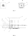
- Fig. 4 shows a device for manipulating and separating objects 1 comprising a first wall 3 and a second wall delimiting the height of a cavity 2.
- the first wall 3 is a reflective wall and the second wall is a transmitter wall 4 to which is fastened and acoustic wave generator 5 for generation of an acoustic field 8.
- Fig. 4 further depicts a light source 6 illuminating an illumination area 7 within the cavity 2.
- Said cavity 2 comprises a liquid and objects comprising a first plurality of objects absorbing in the wavelength of the light source (crosshatched beads) and a second plurality of not absorbing objects (white beads).
- Fig. 4 shows a device for manipulating and separating objects 1 comprising a first wall 3 and a second wall delimiting the height of a cavity 2.
- the first wall 3 is a reflective wall and the second wall is a transmitter wall 4 to which is fastened and acoustic wave generator 5 for generation of an acoustic field 8.
- Fig. 4 further depicts
- the objects when submitted to an acoustic field 8 , the objects form an aggregate in a levitation plane at mid height of the cavity 2. While simultaneously under a light beam 7 and an acoustic field 8 in a first region of the cavity 2 , the absorbing objects are ejected from the aggregate (see Fig. 5 ).
- the objects may be sorted by positioning a first central outlet 10.1 for non-absorbing objects and second and third outlets ( 10.2,10.3 ) for absorbing objects ejected from the aggregate.
- the device may comprise more than one inlet 9 .1 .
- second and third inlets 9.2 , 9.3 supplied with a buffer solution, on each side of the first inlet 9 .1 , supplied with the liquid comprising objects, hydrodynamic focusing centers the objects within the width w of the cavity.
- the second plurality of objects does not absorb light. According to one alternative embodiment, the second plurality of objects absorbs light in a second wavelength range not overlapping with the first wavelength range.
- the method of separating objects may further comprise the step of submitting the aggregate to a light beam emitting at the second wavelength range.
- the method comprises the steps of:
- the third plurality of objects does not absorb light. According to one alternative embodiment, the third plurality of objects absorbs light in a third wavelength range not overlapping with the first and the second wavelength ranges.
- the method may be carried out with more than one plurality of objects and even more than two pluralities of objects.
- Fig . 6 shows indeed three pluralities of objects: optically and acoustically active objects (crosshatched beads), acoustically active objects (black beads) and non-active objects (white beads).
- the acoustically active objects are focused in the levitation plane by acoustic migration while the non-active objects do not migrate.
- the optically active objects are ejected from the aggregate and migrate.
- the method of the present invention may be used for sorting three pluralities of objects or more.
- the acoustically active species may be collected in the center of the levitation plane (1), while the non-active species may be collected in the center of the cavity along the width w (2), perpendicular to the acoustic wave direction and the acoustically and optically species may be collected on the sides of the levitation plane in the center of the cavity along the height h (3).
- each plurality of objects is optically active but with non-overlapping absorption spectrum; thus enabling sequential sorting.
- the invention may, in an exemplary embodiment, relate to a method for acquiring at least one image of objects in a cavity comprising a liquid. Said method comprising:
- the steps of illuminating and acquiring at least one image are performed simultaneously to the manipulating or separating step. According to one embodiment, the steps of illuminating and acquiring at least one image are performed subsequently to the manipulating or separating step.
- the illumination system used for imaging the objects is also used for submitting the objects to the light beam used in the manipulating or sorting methods.
- the present invention in another of its aspects, relates to a device for separating objects in a liquid.
- said device comprises:
- the first region is defined as the region wherein the cavity is submitted to both the acoustic field and the light beam.
- the acoustic wave generator may generate an acoustic field within a second region encompassing the first region and the light source may generate a light beam on a third region encompassing the first region. The first region being in that case the intersection of the second and third regions.
- the at least first, second and third outlets 10.1 , 10.2 , 10.3 are arranged on the same height on the second transverse axis.
- the device further comprises second and third inlets 9.2 , 9.3 , wherein the first inlet 9.1 is arranged on the first transverse axis between the second and third inlets 9.2 , 9.3 .
- the latter embodiment allows hydrodynamic focusing of the objects at the center of the cavity 2 .
- the method described above may be used in at least one of the following applications: methods of sorting species, for example rigid or deformable objects, polydisperse objects, biological cells, notably blood cells, for example cancer cells present in a specimen of blood or globules, bacteria, colloidal or non-colloidal emulsions, proteins or liposomes; methods of diagnosis or analysis; methods of purification, enrichment or depletion of species; methods of synthesis of species; methods of modification of physical or chemical characteristics of species; methods of medicinal product research; methods of mixing or methods of measuring diffusion coefficients.
- methods of sorting species for example rigid or deformable objects, polydisperse objects, biological cells, notably blood cells, for example cancer cells present in a specimen of blood or globules, bacteria, colloidal or non-colloidal emulsions, proteins or liposomes
- methods of diagnosis or analysis methods of purification, enrichment or depletion of species
- methods of synthesis of species methods of modification of physical or chemical characteristics of species
- the method according to the invention may, in particular, be used for the purposes of separating objects initially included in a mixture of polydisperse objects.
- the method of the invention may be used for isolating rare cells of interest (crosshatched bead) among abundant non-interesting cells (white beads).
- rare cells non-absorbing at chosen wavelength such as circular tumoral cells
- abundant cells such as red blood cells
- the non-interesting absorbing objects are expelled from the illuminated area 7 while the interesting non-absorbing objects remains at its position under acoustic levitation.
- the cells of interest may mutatis mutandis be absorbing at a chosen wavelength and the abundant cells may be non-absorbing at said chosen wavelength.
- the absorption differences between polydisperse objects may enable the objects to be separated along the width of the cavity.
- the method according to the invention may also enable filterless filtration to be carried out by selective acoustic focusing and selective light expulsion of the handled objects.
- the modification of the position of the objects may enable said objects to be guided selectively toward a given outlet of the cavity.
- the liquid is an aqueous solution, an organic solution or a mixture thereof. According to one embodiment, the liquid is an emulsion. According to one embodiment, the liquid is a biological liquid such as blood, plasma or any cell culture medium.
- the liquid is transparent to light, especially to visible radiation.
- the liquid may be at rest when the device is in operation.
- the liquid is flowing when the device is in operation.
- the objects are capable of absorbing light in a given wavelength range.
- the objects comprises a first plurality of objects capable of absorbing light in a given wavelength range and a second plurality of objects not capable of absorbing light in a given wavelength range.
- the first plurality of objects may have substantially a same acoustic contrast factor than the second plurality of objects.
- the objects comprise n pluralities of objects, with n ranging from 1 to 10, 100 or 1 000.
- the objects are fluorescent.
- the objects are rigid or deformable objects, polydisperse or monodispersed objects.
- the objects are selected from rigid, elastic, mineral or biological objects.
- the objects are selected from algae, microorganisms, bacteria, viruses, DNA, proteins or leavening.
- the objects are selected from colloidal objects.
- the objects are selected from cells, parts of cells such as cell debris, or cluster of cells; such as for instance blood cells, cancellous cells or epithelial cells.
- the objects are selected from phospholipids, liposomes or vesicles.
- the objects are selected from micro-objects such as metallic microfibers; or nanoobjects such as carbon nanotubes or mixture thereof.
- the objects are self-propelled objects such as bacteria in biological or ionic liquids or micro-/nano-robots.
- the objects may be, for example, monodisperse or polydisperse absorbing biological cells.
- the method according to the invention may be used, for example, in procedures for sorting said biological cells.
- the objects may be monodisperse or polydisperse fluorescent biological cells marked with a fluorescent dye molecule.
- the mean size of the objects present within the cavity may, for example, be less than or equal to 50 micrometers.
- mean size denotes the statistical object size at half the population, called D50.
- the volume fraction of objects within the liquid is higher of 0.025%, notably ranging from 0.025 to 65%, preferably from 0.025 to 35%, more preferably from 5 to 20%.
- the height of the cavity may, at least at a position along the longitudinal axis at which the acoustic waves are generated, be greater than or equal to ten times the mean size of the objects present within the cavity.
- the cavity extends along a longitudinal axis, having a cross-section that present a width measured along a first transverse axis and a height measured along a second transverse axis perpendicular to the first transverse axis; the cavity having first and second walls along the second transverse axis.
- the cavity may have a substantially constant cross section with respect to movement along its longitudinal axis.
- the cavity may have a rectangular cross section over at least a portion of its length, notably over the whole of its length.
- the cavity may have a square or circular cross section over at least a portion of its length, notably over the whole of its length.
- the cavity may have a height in the range from 20 micrometers to a few millimeters, preferably from 100 micrometers to 500 micrometers, over at least a portion of its length, notably over the whole of its length.
- the width of the cavity may be constant or variable with respect to movement along the longitudinal axis of the cavity.
- the cavity may have a width in the range from 1 mm to 30 mm, preferably from 5 mm to 20 mm, over at least a portion of its length, notably over the whole of its length.
- the cavity is a cylindrical cavity.
- the diameter of said cylindrical may be in the range from 10 to 30 millimeters, such as for example 10, 12, 14, 16, 18, 20, 22, 24 or 26 millimeters.
- At least one of the first and second walls of the cavity may be moveable in order to insert a medium inside the cavity, such as, by means of non-limiting example, a liquid medium comprising multiple objects.
- At least one of the first and second walls of the cavity may include, or notably consist of, a material chosen from among the following: mineral or organic glasses, silicon wafer, thermoplastic materials, polycarbonate, Poly(methyl methacrylate), polydimethylsiloxane, metals such as titanium or notably quartz. More generally, any material having a high acoustic impedance, that is to say an acoustic impedance at least ten times greater than that of the liquid, may be used. According to one embodiment, the first and the second walls comprise the same or different materials.
- the wall facing the wall from which the acoustic waves are generated may include, or notably consist of, a material having an acoustic impedance at least ten times greater than that of the liquid.
- the first and second walls of the cavity may be in the form of plates and may have a height in the range from 0.1 mm to 5 mm.
- One of the wall of the cavity may be opaque.
- One of the wall of the cavity if transparent. In a variant, both walls are transparent.
- the use of at least one wall comprising at least one transparent region is required to illuminate the content of the cavity.
- the cavity may be in liquid communication with at least one inlet, preferably two or three inlets.
- the cavity may further be in liquid communication with at least one outlet, preferably two or three outlets.
- the cavity inlet(s) and/or outlet(s) may be connected to syringe pumps and/or peristaltic pumps and/or any device that could drive flow.
- a hydrodynamic dampener may be added between the peristaltic pump and the cavity inlet(s) and/or outlet(s). As such, it may not be necessary to open the cavity in order to collect the formed multilayer aggregates.
- the acoustic field is produced by at least one acoustic field generator.
- the acoustic field generator may be a piezoelectric material, e.g. ceramic.
- the acoustic field has for example, an amplitude ranging from 0.1 V to 50 V, preferably from 1 to 10 V.
- the acoustic field may have, for example, a frequency less than or equal to 20 megahertz, and notably in the range from 0.5 to 10 megahertz. By using these frequency ranges, it may advantageously be possible to handle living cells without damaging them.
- the frequency of the acoustic field is in the range from 0.5f 0 to 1.5f 0 , wherein f 0 is a resonance frequency of the cavity.
- f 0 is a resonance frequency of the cavity.
- the acoustic field is a continuous acoustic field.
- the acoustic field is a pulsed acoustic field.
- the acoustic wave generator may be supplied with a sinusoidal voltage. In a variant, the acoustic wave generator may be supplied with a triangular or square-wave voltage.
- the part of the acoustic field generator in contact with a wall of the cavity may be circular or rectangular.
- the acoustic wave generator may, for example, be fixed to the first or second wall of the cavity. This fixing may be carried out by any way known to persons skilled in the art, notably by gluing.
- the part of the acoustic field generator in contact with a wall (the transmitter wall) of the cavity is annular.
- a light beam may pass through the acoustic field generator.
- the objects are submitted to a first light beam emitting at a first wavelength range through the reflective wall and to a second light beam emitting at a second wavelength range through the opening of the annular transducer and the transmitter wall.
- a layer of acoustic matching material may be present between the acoustic wave generator and at least one of the first and second walls of the cavity.
- the acoustic matching may be provided by using any material known to persons skilled in the art as suitable for this purpose, such as glue, acoustic gels, oil...
- a plurality of acoustic wave generators may be arranged along the transmitter wall of the cavity and may generate acoustic waves from at least one of the first and second walls, said acoustic wave generators possibly being positioned, on the same side of the cavity.
- the use of a plurality of acoustic wave generators is advantageous when the liquid flows at high velocity or when layers of large objects are to be generated.
- the flight time under the generators decreases as the liquid velocity increases. This may require a greater number of transducers to be used in order to achieve focusing.
- the second case in the absence of flow for example, it is possible to use a plurality of acoustic wave generators to form large layers of objects.
- the width/height ratio may be in the range from 1 to 10, notably from 1 to 3.
- an acoustic force field over the height and over the width, it may advantageously be possible to move a set of objects, for example a line of objects, in any area of the cavity, and thus to benefit from a larger number of available locations for the acoustic focusing.
- At least one light source is configured to emit a light beam in a region of the cavity or in the whole cavity.
- the at least one light source may be a laser diode, a laser, a diode, a LED or any other light source known to one skilled in the art.
- the at least one light source may emit light in the range from 200 nm to 1 000 nm, preferably notably from 360 nm to 800 nm.
- the power of the light beam emitted by the light source is ranging from 10 ⁇ W to 200 mW.
- the at least one light source may be placed opposite to the wall from which is generated the acoustic field.
- the at least one light source may be placed on the same wall as the wall from which is generated the acoustic field.
- the light source may be emitted through any transparent wall of the cavity.
- the at least one image of at least some of the objects that are present within the cavity and that are illuminated by the illumination system may be acquired by an image acquisition system.
- the image acquisition system comprises a microscope, such as an inverted microscope or a reflection microscope. In one embodiment, the image acquisition system further comprises a camera.
- the image acquisition system has a lens for focusing the radiation from the objects present in the cavity on a sensor, enabling an image of said objects to be produced.
- the sensor may, for example, be a CCD camera.
- the illumination system may be configured to illuminate some or all of a layer of objects formed by acoustic focusing.
- the illumination system includes a light source which may, for example, include a laser, a diode or a LED.
- the at least one image may be processed by a processing device.
- the processing device may be used to measure the norm and/or direction and/or sense of the velocity vector of at least some of the objects that are present within the cavity and that are illuminated by the illumination system.
- the assembly according to the invention may, notably, be used to execute a method of object image velocimetry.
- the device for processing the at least one image may, for example, include a computer.
- the image processing device may, for example, be configured to calculate a correlation coefficient of the distributions of luminous intensity found in at least two images of objects produced by the image acquisition system.
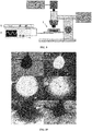
- the cavity is closed by a round quartz cover plate, of height 1.1 mm, acting as the reflective wall while the bottom is made of a silica wafer, of height 0.30 mm, acting as the transmitter wall.
- a square piezoelectric transducer was positioned in contact to the bottom surface of the cavity. Said piezoelectric transducer, 1 mm height and 10 mm side, was glued directly on the silica wafer using a water-soluble glue. As depicted in Fig .
- the piezoelectric transducer is powered by a wave generator F (Tabor Electronics 5200) connected to an amplifier E (Tabor Electronics 3222) allowing variation of the applied voltage from a few mV to more than 10 V.
- the frequency of the sinusoidal signal was tuned to maximize the acoustic radiation force which correspond to the resonance condition, i.e. a wavelength of twice the height of the cylindrical cavity, here 1.85 MHz.
- the illumination system comprises a light source C which allows both white light for imaging as well as a good control of the wavelength of the light beam.
- the acquisition system comprises an microscope D , and recording were made using a high speed camera B connected to a computer A .
- the particles were dispersed in a liquid. Experiments were carried out at a frequency of 1.849 MHz, a transducer supply voltage of 7 V and an illumination power of 20.4 ⁇ W.
- large aggregates of particles are created in acoustic levitation. Once a green light beam illuminates the aggregates in acoustic levitation, the aggregate starts to eject particles. The particles escape the aggregate while remaining in levitation.
- Red blood cells are non-fluorescing particles absorbing in the range of wavelength from 400 to 500 nm.
- the experiments were conducted at a frequency of 1.850 MHz, a transducer supply voltage of 6 V and an illumination power of 20.4 mW.
- large aggregates of red blood cells are created in acoustic levitation. Once a blue light beam illuminates the aggregates in acoustic levitation, the aggregate starts to eject particles. The particles escape the aggregate while remaining in levitation. Once the light beam is turned off, the aggregation process starts again.
- the mixture was focused into an aggregate using a supply voltage of 10.5 V and a frequency of 1.903 MHz.
- the aggregate created by the acoustic force is homogeneous (b shows the green fluorescent particles and c the red fluorescent particles).
- the pictures at the bottom show the aggregate after applying illumination to the particles.
- the green fluorescent particles e) have been extracted from the red ones f) creating two aggregates, one containing the red particles, the other one containing the green particles.
Landscapes
- Chemical & Material Sciences (AREA)
- Health & Medical Sciences (AREA)
- Immunology (AREA)
- Life Sciences & Earth Sciences (AREA)
- General Health & Medical Sciences (AREA)
- Analytical Chemistry (AREA)
- Physics & Mathematics (AREA)
- Pathology (AREA)
- General Physics & Mathematics (AREA)
- Biochemistry (AREA)
- Hematology (AREA)
- Dispersion Chemistry (AREA)
- Engineering & Computer Science (AREA)
- Chemical Kinetics & Catalysis (AREA)
- Clinical Laboratory Science (AREA)
- Biomedical Technology (AREA)
- Urology & Nephrology (AREA)
- Molecular Biology (AREA)
- Biotechnology (AREA)
- Medicinal Chemistry (AREA)
- Signal Processing (AREA)
- Food Science & Technology (AREA)
- Cell Biology (AREA)
- Microbiology (AREA)
- Fluid Mechanics (AREA)
- Physical Or Chemical Processes And Apparatus (AREA)
- Sampling And Sample Adjustment (AREA)
- Ultra Sonic Daignosis Equipment (AREA)
Priority Applications (6)
| Application Number | Priority Date | Filing Date | Title |
|---|---|---|---|
| EP17305848.8A EP3421975A1 (de) | 2017-06-30 | 2017-06-30 | Verfahren und vorrichtung zur manipulation von objekten |
| US16/625,993 US11628438B2 (en) | 2017-06-30 | 2018-06-29 | Methods and device for manipulating objects |
| JP2019572801A JP7177797B2 (ja) | 2017-06-30 | 2018-06-29 | 物体を操作するための方法及び装置 |
| CN201880053608.7A CN111344557B (zh) | 2017-06-30 | 2018-06-29 | 用于操纵物体的方法和设备 |
| EP18738241.1A EP3646011A1 (de) | 2017-06-30 | 2018-06-29 | Verfahren und vorrichtung zur manipulation von objekten |
| PCT/EP2018/067585 WO2019002551A1 (en) | 2017-06-30 | 2018-06-29 | METHODS AND DEVICE FOR HANDLING OBJECTS |
Applications Claiming Priority (1)
| Application Number | Priority Date | Filing Date | Title |
|---|---|---|---|
| EP17305848.8A EP3421975A1 (de) | 2017-06-30 | 2017-06-30 | Verfahren und vorrichtung zur manipulation von objekten |
Publications (1)
| Publication Number | Publication Date |
|---|---|
| EP3421975A1 true EP3421975A1 (de) | 2019-01-02 |
Family
ID=59363055
Family Applications (2)
| Application Number | Title | Priority Date | Filing Date |
|---|---|---|---|
| EP17305848.8A Withdrawn EP3421975A1 (de) | 2017-06-30 | 2017-06-30 | Verfahren und vorrichtung zur manipulation von objekten |
| EP18738241.1A Withdrawn EP3646011A1 (de) | 2017-06-30 | 2018-06-29 | Verfahren und vorrichtung zur manipulation von objekten |
Family Applications After (1)
| Application Number | Title | Priority Date | Filing Date |
|---|---|---|---|
| EP18738241.1A Withdrawn EP3646011A1 (de) | 2017-06-30 | 2018-06-29 | Verfahren und vorrichtung zur manipulation von objekten |
Country Status (5)
| Country | Link |
|---|---|
| US (1) | US11628438B2 (de) |
| EP (2) | EP3421975A1 (de) |
| JP (1) | JP7177797B2 (de) |
| CN (1) | CN111344557B (de) |
| WO (1) | WO2019002551A1 (de) |
Cited By (7)
| Publication number | Priority date | Publication date | Assignee | Title |
|---|---|---|---|---|
| US10704021B2 (en) | 2012-03-15 | 2020-07-07 | Flodesign Sonics, Inc. | Acoustic perfusion devices |
| US10785574B2 (en) | 2017-12-14 | 2020-09-22 | Flodesign Sonics, Inc. | Acoustic transducer driver and controller |
| WO2020245432A1 (fr) * | 2019-06-06 | 2020-12-10 | Centre National De La Recherche Scientifique | Puce microfluidique pour la structuration d'agrégat de cellules par exclusion optique et lévitation acoustique |
| US10975368B2 (en) | 2014-01-08 | 2021-04-13 | Flodesign Sonics, Inc. | Acoustophoresis device with dual acoustophoretic chamber |
| US11214789B2 (en) | 2016-05-03 | 2022-01-04 | Flodesign Sonics, Inc. | Concentration and washing of particles with acoustics |
| US11377651B2 (en) | 2016-10-19 | 2022-07-05 | Flodesign Sonics, Inc. | Cell therapy processes utilizing acoustophoresis |
| US11708572B2 (en) | 2015-04-29 | 2023-07-25 | Flodesign Sonics, Inc. | Acoustic cell separation techniques and processes |
Families Citing this family (4)
| Publication number | Priority date | Publication date | Assignee | Title |
|---|---|---|---|---|
| EP3730213A1 (de) * | 2019-04-24 | 2020-10-28 | AcouSort AB | Verfahren und system zur akustischen trennung von festbettzellen |
| KR102390074B1 (ko) * | 2021-12-16 | 2022-04-25 | 주식회사 유앤유 | 미세조류이미지 연속 측정장치 |
| JP7803135B2 (ja) * | 2022-01-20 | 2026-01-21 | セイコーエプソン株式会社 | 流体デバイスおよび流体デバイスの制御方法 |
| CN116297217A (zh) * | 2023-02-27 | 2023-06-23 | 浙江省水利水电勘测设计院有限责任公司 | 光声系统耦合测量组分流与颗粒流的装置与方法 |
Citations (9)
| Publication number | Priority date | Publication date | Assignee | Title |
|---|---|---|---|---|
| US20060096353A1 (en) | 2002-09-16 | 2006-05-11 | The Secretary Of State For Defence | Apparatus for directing particles in a fluid |
| US20080067128A1 (en) | 2005-03-11 | 2008-03-20 | Centre National De La Recherche Scientifique | Fluid separation device |
| WO2008122051A1 (en) * | 2007-04-02 | 2008-10-09 | Acoustic Cytometry Systems, Inc. | Methods and devices for enhanced analysis of field focused cells and particles |
| US20090158823A1 (en) * | 2007-12-19 | 2009-06-25 | Gregory Kaduchak | Particle analysis in an acoustic cytometer |
| US20120225475A1 (en) * | 2010-11-16 | 2012-09-06 | 1087 Systems, Inc. | Cytometry system with quantum cascade laser source, acoustic detector, and micro-fluidic cell handling system configured for inspection of individual cells |
| US20150037863A1 (en) | 2012-02-06 | 2015-02-05 | Centre National De La Recherche Scientifique | Method of forming a multilayer aggregate of objects |
| US20150285719A1 (en) | 2012-02-27 | 2015-10-08 | Centre National De La Recherche Scientifique | Method of forming an aggregate of objects |
| US20160231223A1 (en) * | 2015-02-10 | 2016-08-11 | Capitalbio Corporation | Fluidic chip for flow cytometry and methods of use |
| WO2017006093A1 (en) * | 2015-07-03 | 2017-01-12 | University Of Dundee | Manipulating methods and apparatus |
Family Cites Families (13)
| Publication number | Priority date | Publication date | Assignee | Title |
|---|---|---|---|---|
| JPH1048102A (ja) * | 1996-07-31 | 1998-02-20 | Hitachi Ltd | 光学ピンセット |
| CN1973413A (zh) * | 2004-03-17 | 2007-05-30 | 阿尔利克斯公司 | 使用全息光学捕获来操控和处理材料的系统和方法 |
| US7586684B2 (en) * | 2005-01-21 | 2009-09-08 | New York University | Solute characterization by optoelectronkinetic potentiometry in an inclined array of optical traps |
| DE602005016736D1 (de) * | 2005-07-07 | 2009-10-29 | Fraunhofer Ges Forschung | Tion von partikeln, zellen und viren |
| FR2901717A1 (fr) | 2006-05-30 | 2007-12-07 | Centre Nat Rech Scient | Procede de traitement de gouttes dans un circuit microfluidique. |
| CN102170949A (zh) * | 2008-10-08 | 2011-08-31 | 福斯分析股份公司 | 利用驻波型超声波分离液体中的颗粒 |
| FR2979256B1 (fr) | 2011-08-30 | 2014-09-26 | Centre Nat Rech Scient | Dispositif de manipulation d'objets par champs de force acoustique |
| US9170186B2 (en) | 2012-06-06 | 2015-10-27 | Centre National De La Recherche Scientifique | Method of manipulating objects |
| JP6025982B2 (ja) | 2012-08-01 | 2016-11-16 | ザ・ペン・ステート・リサーチ・ファンデーション | 粒子および細胞の高効率分離およびマニピュレーション |
| CN107430050B (zh) | 2015-01-12 | 2022-05-17 | 仪器实验室公司 | 用于生物医学感测和检测的含颗粒溶液中颗粒的空间分离 |
| NL2014262B1 (en) * | 2015-02-09 | 2016-10-13 | Stichting Vu | Apparatus and method for controlling a plurality of optical traps. |
| ES2918336T3 (es) * | 2015-04-30 | 2022-07-15 | European Molecular Biology Laboratory | Detección y clasificación de gotas microfluídicas |
| US10161926B2 (en) * | 2015-06-11 | 2018-12-25 | Flodesign Sonics, Inc. | Acoustic methods for separation of cells and pathogens |
-
2017
- 2017-06-30 EP EP17305848.8A patent/EP3421975A1/de not_active Withdrawn
-
2018
- 2018-06-29 JP JP2019572801A patent/JP7177797B2/ja active Active
- 2018-06-29 US US16/625,993 patent/US11628438B2/en active Active
- 2018-06-29 EP EP18738241.1A patent/EP3646011A1/de not_active Withdrawn
- 2018-06-29 CN CN201880053608.7A patent/CN111344557B/zh active Active
- 2018-06-29 WO PCT/EP2018/067585 patent/WO2019002551A1/en not_active Ceased
Patent Citations (9)
| Publication number | Priority date | Publication date | Assignee | Title |
|---|---|---|---|---|
| US20060096353A1 (en) | 2002-09-16 | 2006-05-11 | The Secretary Of State For Defence | Apparatus for directing particles in a fluid |
| US20080067128A1 (en) | 2005-03-11 | 2008-03-20 | Centre National De La Recherche Scientifique | Fluid separation device |
| WO2008122051A1 (en) * | 2007-04-02 | 2008-10-09 | Acoustic Cytometry Systems, Inc. | Methods and devices for enhanced analysis of field focused cells and particles |
| US20090158823A1 (en) * | 2007-12-19 | 2009-06-25 | Gregory Kaduchak | Particle analysis in an acoustic cytometer |
| US20120225475A1 (en) * | 2010-11-16 | 2012-09-06 | 1087 Systems, Inc. | Cytometry system with quantum cascade laser source, acoustic detector, and micro-fluidic cell handling system configured for inspection of individual cells |
| US20150037863A1 (en) | 2012-02-06 | 2015-02-05 | Centre National De La Recherche Scientifique | Method of forming a multilayer aggregate of objects |
| US20150285719A1 (en) | 2012-02-27 | 2015-10-08 | Centre National De La Recherche Scientifique | Method of forming an aggregate of objects |
| US20160231223A1 (en) * | 2015-02-10 | 2016-08-11 | Capitalbio Corporation | Fluidic chip for flow cytometry and methods of use |
| WO2017006093A1 (en) * | 2015-07-03 | 2017-01-12 | University Of Dundee | Manipulating methods and apparatus |
Cited By (10)
| Publication number | Priority date | Publication date | Assignee | Title |
|---|---|---|---|---|
| US10704021B2 (en) | 2012-03-15 | 2020-07-07 | Flodesign Sonics, Inc. | Acoustic perfusion devices |
| US10975368B2 (en) | 2014-01-08 | 2021-04-13 | Flodesign Sonics, Inc. | Acoustophoresis device with dual acoustophoretic chamber |
| US11708572B2 (en) | 2015-04-29 | 2023-07-25 | Flodesign Sonics, Inc. | Acoustic cell separation techniques and processes |
| US11214789B2 (en) | 2016-05-03 | 2022-01-04 | Flodesign Sonics, Inc. | Concentration and washing of particles with acoustics |
| US11377651B2 (en) | 2016-10-19 | 2022-07-05 | Flodesign Sonics, Inc. | Cell therapy processes utilizing acoustophoresis |
| US10785574B2 (en) | 2017-12-14 | 2020-09-22 | Flodesign Sonics, Inc. | Acoustic transducer driver and controller |
| WO2020245432A1 (fr) * | 2019-06-06 | 2020-12-10 | Centre National De La Recherche Scientifique | Puce microfluidique pour la structuration d'agrégat de cellules par exclusion optique et lévitation acoustique |
| FR3096905A1 (fr) * | 2019-06-06 | 2020-12-11 | Centre National De La Recherche Scientifique | Puce microfluidique pour la structuration d’agrégat de cellules par exclusion optique et lévitation acoustique. |
| CN114096351A (zh) * | 2019-06-06 | 2022-02-25 | 法国国家科学研究中心 | 用于通过光学排斥和声悬浮构建细胞聚集体的微流控芯片 |
| JP2022536104A (ja) * | 2019-06-06 | 2022-08-12 | サントル ナシオナル ドゥ ラ ルシェルシェ シアンティフィク | 光学的排除および音響浮揚によって細胞凝集体を構造化するためのマイクロ流体チップ |
Also Published As
| Publication number | Publication date |
|---|---|
| JP2020525276A (ja) | 2020-08-27 |
| US11628438B2 (en) | 2023-04-18 |
| US20210154661A1 (en) | 2021-05-27 |
| WO2019002551A1 (en) | 2019-01-03 |
| CN111344557B (zh) | 2023-04-07 |
| EP3646011A1 (de) | 2020-05-06 |
| JP7177797B2 (ja) | 2022-11-24 |
| CN111344557A (zh) | 2020-06-26 |
Similar Documents
| Publication | Publication Date | Title |
|---|---|---|
| US11628438B2 (en) | Methods and device for manipulating objects | |
| CN103906555B (zh) | 利用声力场处理对象的装置 | |
| EP2879778B1 (de) | Hocheffektive trennung und sortierung von partikeln und zellen | |
| EP1774283B1 (de) | Ultraschallanalytkonzentration und anwendung bei durchflusszytometrie | |
| US8865003B2 (en) | Apparatus and method for separation of particles suspended in a liquid from the liquid in which they are suspended | |
| US8767212B2 (en) | Devices and methods for detecting and sorting biological particles in a liquid flow using substantially uniform intensity along a direction of flow of a flow cell | |
| US6833542B2 (en) | Method for sorting particles | |
| US9733171B2 (en) | Acoustic concentration of particles in fluid flow | |
| US6815664B2 (en) | Method for separation of particles | |
| EP0773055B1 (de) | Apparat zur Behandlung von Teilchen durch akustische Strahlung | |
| US8714014B2 (en) | System and method for acoustic focusing hardware and implementations | |
| US6784420B2 (en) | Method of separating particles using an optical gradient | |
| CN102170949A (zh) | 利用驻波型超声波分离液体中的颗粒 | |
| EA022506B1 (ru) | Анализ частиц в акустическом цитометре | |
| US20020108859A1 (en) | Methods for modifying interaction between dielectric particles and surfaces | |
| US20020115163A1 (en) | Methods for sorting particles by size and elasticity | |
| EP2820393B1 (de) | Verfahren zur herstellung eines aggregats aus objekten | |
| US20020121443A1 (en) | Methods for the combined electrical and optical identification, characterization and/or sorting of particles | |
| US20020113204A1 (en) | Apparatus for collection of sorted particles | |
| US11698364B2 (en) | Real-time cell-surface marker detection | |
| US10933429B2 (en) | Separation of nanoparticles via acoustofluidic flow relocation | |
| Bakhtiari et al. | Automated microparticle positioning using a pair of ultrasound-actuated microbubbles for microfluidic applications | |
| WO2023163162A1 (ja) | 液滴内の粒子の検出方法と、その粒子を含む液滴の分取と分注方法と分注後に液滴から粒子を外部に取り出す方法と、その装置 | |
| CN216309741U (zh) | 基于移动聚焦表面声束的荧光激活细胞分选系统 | |
| CN113916753A (zh) | 基于移动聚焦表面声束的荧光激活细胞分选系统及分选方法 |
Legal Events
| Date | Code | Title | Description |
|---|---|---|---|
| PUAI | Public reference made under article 153(3) epc to a published international application that has entered the european phase |
Free format text: ORIGINAL CODE: 0009012 |
|
| STAA | Information on the status of an ep patent application or granted ep patent |
Free format text: STATUS: THE APPLICATION HAS BEEN PUBLISHED |
|
| AK | Designated contracting states |
Kind code of ref document: A1 Designated state(s): AL AT BE BG CH CY CZ DE DK EE ES FI FR GB GR HR HU IE IS IT LI LT LU LV MC MK MT NL NO PL PT RO RS SE SI SK SM TR |
|
| AX | Request for extension of the european patent |
Extension state: BA ME |
|
| STAA | Information on the status of an ep patent application or granted ep patent |
Free format text: STATUS: THE APPLICATION IS DEEMED TO BE WITHDRAWN |
|
| 18D | Application deemed to be withdrawn |
Effective date: 20190703 |