EP3425265A1 - Phare ajustable - Google Patents
Phare ajustable Download PDFInfo
- Publication number
- EP3425265A1 EP3425265A1 EP18177430.8A EP18177430A EP3425265A1 EP 3425265 A1 EP3425265 A1 EP 3425265A1 EP 18177430 A EP18177430 A EP 18177430A EP 3425265 A1 EP3425265 A1 EP 3425265A1
- Authority
- EP
- European Patent Office
- Prior art keywords
- board
- headlight
- board unit
- headlamp
- heat sink
- Prior art date
- Legal status (The legal status is an assumption and is not a legal conclusion. Google has not performed a legal analysis and makes no representation as to the accuracy of the status listed.)
- Granted
Links
Images


Classifications
-
- F—MECHANICAL ENGINEERING; LIGHTING; HEATING; WEAPONS; BLASTING
- F21—LIGHTING
- F21S—NON-PORTABLE LIGHTING DEVICES; SYSTEMS THEREOF; VEHICLE LIGHTING DEVICES SPECIALLY ADAPTED FOR VEHICLE EXTERIORS
- F21S45/00—Arrangements within vehicle lighting devices specially adapted for vehicle exteriors, for purposes other than emission or distribution of light
- F21S45/40—Cooling of lighting devices
- F21S45/47—Passive cooling, e.g. using fins, thermal conductive elements or openings
-
- F—MECHANICAL ENGINEERING; LIGHTING; HEATING; WEAPONS; BLASTING
- F21—LIGHTING
- F21S—NON-PORTABLE LIGHTING DEVICES; SYSTEMS THEREOF; VEHICLE LIGHTING DEVICES SPECIALLY ADAPTED FOR VEHICLE EXTERIORS
- F21S41/00—Illuminating devices specially adapted for vehicle exteriors, e.g. headlamps
- F21S41/10—Illuminating devices specially adapted for vehicle exteriors, e.g. headlamps characterised by the light source
- F21S41/19—Attachment of light sources or lamp holders
-
- F—MECHANICAL ENGINEERING; LIGHTING; HEATING; WEAPONS; BLASTING
- F21—LIGHTING
- F21S—NON-PORTABLE LIGHTING DEVICES; SYSTEMS THEREOF; VEHICLE LIGHTING DEVICES SPECIALLY ADAPTED FOR VEHICLE EXTERIORS
- F21S41/00—Illuminating devices specially adapted for vehicle exteriors, e.g. headlamps
- F21S41/60—Illuminating devices specially adapted for vehicle exteriors, e.g. headlamps characterised by a variable light distribution
- F21S41/65—Illuminating devices specially adapted for vehicle exteriors, e.g. headlamps characterised by a variable light distribution by acting on light sources
- F21S41/657—Illuminating devices specially adapted for vehicle exteriors, e.g. headlamps characterised by a variable light distribution by acting on light sources by moving light sources
Definitions
- the invention relates to an adjustable headlamp system for motor vehicles.
- the present invention relates to a headlamp system having a positionally adjustable LED (light emitting diode) light source.
- a headlight may comprise an array of LED modules, each LED module having an LED light source and optics.
- the headlamp system may be configured so that the low beam is provided not only by an LED light source, but by two or more LED modules. By controlling such an array of LED modules, it is possible to variably adjust the light distribution of the headlamp. As a result, the headlight can be adapted, for example, to a changed traffic situation in order to realize a light assistance system.
- a problem with the use of LED light sources is that as much cooling as possible must be provided so as not to reduce the efficiency and the life of the LED light source.
- the cooling must be provided in addition to the electronics, which is required to control the LED light source. It has been assumed that the board on which the LED light source is arranged, must be rigidly attached to the heat sink in order to achieve the required cooling capacity. Both the cooling and the electronics not only limit the available space, but also complicate the realization of an adjustable headlamp system.
- adjustable headlamp systems have proven to be more efficient in terms of lighting technology and can thereby provide higher power. Due to the adjustability, it is possible in particular to compensate for component and joining tolerances.
- Significant adjustable headlight systems are in particular for such headlight systems, which have a primary optics and a secondary optics, which are arranged one after the other in the beam path of the headlight light.
- the position of the primary optic relative to the secondary optics can influence the light-dark border as well as the quality and intensity of the light distribution.
- the adjustability is further for headlight systems in which a light function is provided by means of an array of LED modules.
- a light function is provided by means of an array of LED modules.
- an adjustability of the LED modules relative to each other is advantageous.
- the individual LED modules should be made as small as possible. Due to the small size but also the light characteristic is more sensitive to tolerances.
- the present disclosure particularly shows that a guided movement of the circuit board, on which the light source is arranged, can be realized relative to a heat sink by means of a fixing element, which presses the circuit board against the heat sink during the guided movement.
- the headlamp system may include a circuit board unit.
- the board unit may include a board and a light source.
- the light source can be arranged on the circuit board.
- the light source may be configured to generate spotlight.
- the headlamp system may include a heat sink.
- the heat sink may have a thermal contact surface.
- the board unit may be in contact with the thermal contact surface, ie in particular adjacent to each other.
- the headlamp system may be configured to provide guided movement of the board unit relative to the heat sink. The guided movement can be achieved by means of the thermal contact surface be guided.
- the headlamp system may have a fixing element.
- the fixing member may be configured to push the board unit against the thermal contact surface during the guided movement.
- the light source can be configured as LED (light emitting diode).
- the LED can be arranged on the board.
- the circuit board may have at least part of a circuit for driving the LEDs and / or at least part of a circuit for powering the LED.
- at least some of these functions are integrated on one or more boards, which are arranged separately from the board unit.
- the board may be at least partially formed as a metal core board, in particular as an aluminum core board.
- the board is at least partially configured as an epoxy resin board or as a ceramic board.
- the thermal contact surface may be arranged in a plane.
- the thermal contact surface may be parallel or substantially parallel to a major plane of the board.
- the contact between the thermal contact surface and the board unit may be flat.
- the guided movement may be parallel or substantially parallel to a board main plane of the board.
- the headlamp can be configured so that the board unit via the thermal contact surface one-dimensional or two-dimensionally guided is movable.
- the fixing member may fix the board unit relative to the heat sink in a direction perpendicular to the plane of the heat contact surface.
- One or more headlamp optical elements emitted from the light source may be fixedly connected to the board. These components can be part of the board unit.
- Optical elements can be, for example, lenses, mirrors or diaphragms.
- the mirrors can be plane mirrors, concave mirrors or convex mirrors.
- a surface of a side of the board unit facing away from the light source is in heat-conductive contact with the heat-contact surface, i. especially contiguous.
- the heat-conducting contact takes place at least partially by means of a heat-conducting means of the headlight system.
- the heat conducting means may comprise, for example, a thermal compound and / or a heat conducting foil.
- the heat conducting means may be electrically conductive or insulating.
- the heat-conducting medium can be arranged between a surface of the board unit and the heat-contact surface.
- the heat-conducting contact between the board unit and the thermal contact surface is not adjacent to each other, but via the heat conduction.
- the heat conducting means may be part of the heat sink and in particular form the heat contact surface of the heat sink. Additionally or alternatively, the heat conducting part of the Be board unit and be in heat-conductive contact, in particular adjacent heat-conducting contact with the thermal contact surface of the heat sink.
- the heat sink may have a heat sink.
- the heat sink may be stationary during the guided movement of the sinker unit.
- the heat sink may be part of an active or passive cooling system of the headlamp system.
- the fixing element is configured as an elastic fixing element.
- the fixing element may have a bending spring, in particular a leaf spring.
- the leaf spring may have one or more spring arms.
- the spiral spring can be fixed to the heat sink (in particular fixed).
- the headlight system has a movable headlight optics, which is arranged in a beam path of the headlight light.
- the beam path can be defined as the sum of all the light rays emanating from the light source and which form the vehicle exterior lighting.
- the headlamp system may be configured so that the board movement and the movable headlamp optics perform a joint movement due to the guided movement.
- the movable headlamp optics may be stationary relative to the board unit.
- the guided movement may be perpendicular or substantially perpendicular to a direction of a light beam of the beam path, wherein the direction is measured at a point at which the light beam exits the movable headlight optics.
- the movable headlight optics may include one or more optical elements.
- the optical elements can be configured as transmissive and / or as reflective optical elements.
- the movable headlight optics may have a collector optics and / or a collimating optics.
- the fixing element is designed to generate a force during the guided movement, by means of which the movable headlight optics is fixed relative to the board unit.
- the fixing element can press the movable headlight optics against the board unit.
- the movable headlight optics regardless of the force of the fixing element, is firmly connected to the board unit, for example by gluing.
- the movable headlamp optics can transmit a force for pressing the board unit against the thermal contact surface via the movable headlamp optics.
- the headlight system has a light exit headlight optics, which is arranged in the beam path of the headlight light.
- the light exit headlight optics can be arranged downstream of the movable headlight optics.
- the light exit headlight optics, in the light path of the headlight light be arranged downstream of the movable headlight optics.
- the headlamp system may be designed so that the headlamp light leaves the headlamp system through the light exit headlamp optics.
- the headlamp system may be configured such that the light exit headlamp optics are stationary relative to the heat sink during the guided movement.
- the light exit headlight optics can have one or more optical elements.
- the optical elements can be configured as transmissive and / or as reflective optical elements.
- the headlamp system has a board actuator, in particular a set screw.
- the board actuator may be configured to adjust a position of the board unit through the guided movement.
- a force application angle between a direction of advancement movement of the board actuator and a direction of guided movement of the board unit thereby generated may be greater than 20 degrees, or greater than 40 degrees, or greater than 60 degrees, or greater than 90 degrees, or greater than or equal to 95 degrees.
- the force application angle can be less than 140 degrees.
- the force application angle may be measured to be zero when the advancing direction of the board actuator and the movement direction of the board unit generated thereby are oriented in parallel and in the same direction.
- the board actuator may be stored in stock in the heat sink.
- a bearing for this purpose, for example, a threaded bushing act, which is connected to the heat sink and in which the board actuator is mounted.
- the board actuator can, for example, on the board unit, in particular on the board, and / or attack on the movable headlight optics.
- the board actuator may engage an attack surface that faces away from the light source.
- the attack surface may be angled to the plane of the thermal contact surface and / or angled to the board main plane.
- An angle of angulation may be greater than 20 degrees, or greater than 30 degrees, or greater than 40 degrees, or greater than 50 degrees.
- the angle of the bend may be less than 90 degrees, less than 80 degrees, or less than 70 degrees.
- the angle of the bend can be measured over an area outside the board unit. In other words, the angle of the bend can be measured so that it does not extend through the board unit.
- the board actuator may have a portion which tapers in the region of the force application point.
- the sinker actuator can perform a rotational movement about a feed axis of the sinker actuator.
- the sinker actuator may have a feed thread which converts a rotation of the sinker actuator into a feed motion.
- a force application point of the board actuator shifts on the engagement surface in accordance with the guided movement of the board unit.
- the force application angle may be the same or substantially the same.
- the headlamp system comprises a board reset component.
- the board reset component may be configured to generate a restoring force to a restoring force of the board actuator.
- the board reset component may be formed integrally with the fixing element.
- the one-piece component may have two sections which are angled relative to one another. A first of the two sections may be at least a part of the fixing element and the second section may be at least part of the Be board reset component. Each of the sections may comprise a spring arm of a spiral spring.
- the board unit is movable in two dimensions.
- the headlamp system may have a guide element.
- the headlamp system may be configured such that the board unit is guided relative to the guide member in the direction of a first axis of the two-dimensional guide.
- the headlight system may be configured such that the guide element is guided relative to the heat sink in the direction of a second axis of the two-dimensional guide.
- the headlamp system may include a cross guide for guiding the board unit relative to the heat sink.
- the cross guide may have the guide element.
- the first and second axes may be non-parallel, perpendicular or substantially perpendicular.
- the guide member may be in leading engagement with the heat sink, with the board unit, and / or with the moveable headlamp optics.
- the headlamp system comprises a guide element actuator.
- the guide member actuator may be configured to engage the guide member.
- the guide member actuator may be configured to adjust a position of the guide member relative to the heat sink.
- the headlamp system may further include a guide member return component.
- the guide member return component may be configured to generate a restoring force to a restoring force of the guide member actuator.
- the guide element return component may be connected to the fixing element be formed integrally.
- the one-piece component may have two sections which are angled relative to one another. A first of the two sections may be at least part of the fixing element and the second section may be at least part of the guide element return component. Each of the sections may comprise a spring arm of a spiral spring.
- the fixing element, the board return component and / or the guide element restoring component is formed of flat material or at least partially configured as a bending spring.
- the spiral spring can be a leaf spring.
- the spiral spring can be fixed to the heat sink (in particular fixed). As a result, a support of the spiral spring can be effected on the heat sink.
- the fixing element, the board reset component and / or the guide element restoring component each have a spring arm of a leaf spring.
- the headlamp system may be configured so that an edge of the spring arm is spaced from a surface region of the spring arm, via which a spring force of the spring arm is transmitted.
- a force application point on which the board actuator engages and a force application point on which the board reset component engages define a common line on which both Force application points are arranged.
- the straight line can form an angle to a guideway of a one-dimensional guidance or to an axis of a two-dimensional guidance.
- the guided movement of the board unit can be effected relative to the heat sink.
- the angle may be less than 20 degrees or less than 10 degrees or less than 5 degrees.
- the straight line can be aligned along the axis or along the guideway.
- the force application points may be arranged opposite or substantially opposite one another relative to the light source.
- the FIG. 1 shows a sectional view of a headlamp system 1 according to a first embodiment.
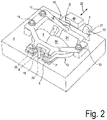
- the FIG. 2 is an associated perspective view showing the below explained components heat sink, primary headlight optics, board unit and fixing.
- the FIG. 3 is a top view of the in the FIG. 2 shown components.
- the Indian FIG. 1 shown section AA is in the FIG. 3 marked by a cut line.
- the sight of the FIG. 3 is in the FIG. 1 characterized by the section line BB.
- the figures do not correspond in every detail.
- the headlamp system 1 has a board unit 2.
- the circuit board unit 2 comprises a circuit board 5 and a light source 4 arranged on the circuit board 5, which is configured as an LED (light emitting diode).
- the circuit board 5 has a circuit for supplying the LED with operating current. Furthermore, the circuit is configured to process input signals by means of which the LED can be controlled. Via a connector 49, the circuit board 5 with a controller and / or a power supply (not shown in the figures) connectable.
- the headlamp system 1 has a primary headlamp optics 12 to focus headlight, which was emitted from the light source 4, and to direct to a secondary headlamp optics 8.
- the primary headlamp optics 12, which focuses the headlamp light of the light source 4 has the reflectors 6, 7, 50 and 24 (shown in FIGS Figures 2 and 3 ) on.
- the primary headlight optics 12 additionally or alternatively has one or more refractive optical elements, such as lenses.
- the secondary headlight optics 8 is configured as a projection lens. Due to the secondary headlight optics 8, the headlight light leaves the headlight system 1.
- the secondary headlight optics 8 can therefore be referred to as light exit headlight optics.
- the secondary headlight optics additionally or alternatively has one or more reflective optical elements, such as mirrors.
- a surface of the board unit 2 which is remote from the light source 4 (such as a surface of the back of the board 5) in surface contact with a thermal contact surface 10 of a heat sink 3.
- the heat contact surface 10 is in a plane arranged.
- the thermal contact surface 10 therefore prevents movements of the board unit 2 which are not parallel to the plane of the thermal contact surface 10. Therefore, in the guided movement, the board unit 2 is moved in a direction parallel to the board main plane PE (shown in FIG FIG. 1 ) of the board 5 out.
- the guided motion may be substantially perpendicular to a direction of a light beam 38 (shown in FIG FIG. 1 ) of the headlight light, the direction of a The position at which the light beam exits the primary headlight optics 12 is measured.
- the primary headlamp optics 12 During the guided movement, the primary headlamp optics 12 remain in fixed position and orientation relative to the board unit 2. Therefore, the primary headlamp optics 12 may be referred to as movable headlamp optics 12.
- the primary headlamp optics 12 may be fixed relative to the board unit 2 for all directions parallel to the board main plane PE .
- this can be done by projections of the primary headlight optics 12, which engage in corresponding recesses of the board unit 2.
- the fixing of the primary headlight optics 12 relative to the board unit 2 can be effected by the pressing force of the fixing element 11.
- the primary headlight optics 12 firmly connected to the board unit 2, for example glued, is.
- the headlight system 1 of the first embodiment provides an adjustability in which the light source 4 and the primary headlamp optical system 12 are adjustable in position relative to the secondary headlamp optical system 8 together.
- the holder of the secondary headlight optics 8 in the headlamp system 1 is configured so that the position and / or orientation of the secondary headlamp optics 8 is independent of the joint guided movement of the board unit 2 and the primary headlamp optics 12 adjustable.
- the board unit 2 is guided by further guide elements with respect to the heat sink 3, which restricts the guided movement of the board unit 2 within the guide plane, which is defined by the thermal contact surface 10, to a linear guideway 22.
- These guide elements are in the FIGS. 1 to 3 Not shown.
- the board unit 2 for example, at least two elongated recesses, such as slots.
- the elongated recesses extend parallel to the guide track 22.
- the heat sink 3 has at least two projections, which also in the FIGS. 1 to 3 are not shown. Each of the projections of the heat sink 3 engages in one of the elongate recesses of the board unit 2.
- the headlamp system 1 has a fixing element 11, which is configured in the embodiment shown as a leaf spring, which is formed from flat material.
- the fixing element 11 is designed so that during the guided movement, the board unit 2 is pressed against the thermal contact surface 10 of the heat sink 3.
- the fixing element 11 is fixed by means of fixing screws 13, 14 and 15 to the heat sink 3 (ie, in particular fastened), whereby the fixing element 11 is supported on the heat sink 3.
- the fixing element 11 also has three spring arms 16, 17 and 18, which engage at three points on the primary headlight optics 12.
- the pressing force, which is generated by the fixing element 11, is transmitted to the board unit 2 via the primary headlight optics 12. As a result, the board unit 2 is pressed against the thermal contact surface 10.
- the headlamp system 1 may have additional fixing means for fixing the board unit 2 in a set position. For example, an additional fixation can be done by clamping or adhesive.
- the headlamp system 1 has a board actuator 19, which is configured as a set screw in the embodiment shown.
- the adjusting screw is arranged in a threaded bushing 20, which has a counter-screw corresponding to the adjusting screw.
- the screw is a self-tapping screw.
- a force application angle ⁇ of the attack of the board actuator 19 on the board unit 2 is greater than zero.
- the force application angle is an angle between a direction vector of a feed movement of the board actuator 19 (for example, in FIG Direction of the force application point P as shown by the arrow 21) and a direction vector of the motion of the board unit 2 generated thereby (as shown by the arrow 48).
- the force application angle ⁇ which is greater than zero, a translation between the advancing movement of the board actuator 19 and the guided movement of the board unit 2 can be effected. This allows a precise adjustment of the headlamp system.
- the force application angle ⁇ is greater than or equal to 95 degrees. This allows a space-saving arrangement of the board actuator 19 on one side of the board unit 2, which is remote from the light source 4.
- the force application point P at which the board actuator 19 acts on the board unit 2, is located on an attack surface A, which is angled relative to the board main plane PE .
- the attack surface A is a surface of an angled portion 25 of the board 5.
- the angle ( ⁇ ) of the bend is greater than 60 degrees and less than 80 degrees.
- attack surface A is a surface of the primary headlight optics 12.
- the force application point P moves along the attack surface A.
- the headlamp system 1 has a board reset component 23 which is configured to generate a counterforce to the actuating force of the board actuator 19. Due to the counterforce, the board unit 2 is pressed against the board actuator 19.
- the board reset component 23 is configured as a spring arm of a leaf spring, which at a force application point Q at a projection 46 of the primary headlight optics 12 attacks.
- the spring arm of the board reset component 23 acts on the board unit 2.
- a free end portion of the spring arm is supported on a projection 31 which protrudes from the heat sink 3 and is rigidly connected thereto or formed integrally with the heat sink 3.
- the thermally conductive contact between the board unit 2 and the thermal contact surface 10 may be in particular a contiguous contact.
- a surface of the board 5 may be in contiguous contact with the thermal contact surface 10 (particularly with a surface of the heat sink).
- a low friction for the guided movement of the board unit 2 relative to the heat sink 3 and a high thermal conductivity for the heat transfer from the board 5 to the heat sink 3 can be obtained if the adjoining surfaces of the heat transfer in each case a high flatness and / or a low roughness respectively.
- the pressing force of the fixing element 11 can be increased without impairing the function of the board reset component 23.
- a smaller force of the board actuator 19 is sufficient to move the board unit 2.
- the force of the sinker actuator 19 on the angled attack surface A then counteracts to a lesser extent the pressing force of the fixing element 11.
- the heat-conducting contact via a lubricating medium, which is arranged between a surface of the board unit 2 and the thermal contact surface 10.
- the lubricating medium may be configured to reduce the friction between the surface of the board unit 2 and the thermal contact surface 10.
- the heat-conductive contact between the board unit 2 and the thermal contact surface 10 is at least partially not adjacent to each other.
- the heat-conducting contact can be made at least partially by means of a heat-conducting medium.
- the heat transfer medium can act as a lubricant.
- the heat conducting means may comprise, for example, a thermal compound and / or a heat conducting foil.
- the heat conducting agent may be configured to be insulating. Thereby, a configuration is conceivable in which a galvanic separation between the board 5 and the heat sink 3 by means of the heat-conducting takes place.
- the heat-conducting agent may comprise, for example, silicone oil and / or zinc oxide.
- a thermal conductivity of the heat-conducting medium can have a value between 0.1 W / (m.K) and 30 W / (m.K), in particular a value between 0.3 W / (m.K) and 20 W / (m.K) ) respectively.
- an increased heat conductivity for the heat transfer can further by the arrangement of the force application points for the board actuator 19 (force application point P in the FIGS. 1 to 3 ), as well as for the board reset component 23 (force application point Q).
- the force application point Q on which the board return component 23 engages and the point of application of force P on which the board actuator 19 engages define a straight line 53 (shown in FIG FIG. 3 ) on which both force application points P and Q are arranged.
- the headlight system 1 is designed such that in this projection the straight line 53 has an angle ⁇ to the guide track 22 which is less than 20 degrees, less than 10 degrees, or less than 5 degrees.
- the straight line 53 can be aligned along the guideway 22.
- the force application points P and Q may be arranged opposite or substantially opposite one another relative to the light source 4.
- the board reset component 23 is integrally formed with the fixing element 11. This facilitates the assembly, since the fixing element 11 and the board reset component 23 can be mounted together by means of the fixing screws 13, 14 and 15.
- the one-piece component has a first portion and a second portion.
- the first portion includes the spring arms 16, 17 and 18 while the second portion provides the spring arm of the board return component 23.
- the sections are angled relative to each other.
- the spring arms 16, 17 and 18 of the fixing element 11 and the board return component 23 and the surfaces of the primary headlight optics 12 are configured so that the force application region, via which the spring force of the respective spring arm is transmitted, is spaced from an edge of the spring arm.
- the area of the primary headlight optics 12, on which the fixing element 11 or the board return component 23 engages is protected from contact with a ridge of the spring arm, which may be present at the edge of the spring arm due to the production.
- contact of the burr with the primary headlamp optics 12 is disadvantageous because it damages the primary headlamp optics 12 and / or increases the friction for the guided movement of the board unit 2.
- increased friction may cause a feed of the board actuator 19 (shown in FIG FIG. 1 ) to the force application point P causes the board 5 does not move as intended, but too much of the thermal contact surface 10th is pushed away, so that the effectiveness of the heat dissipation is impaired.
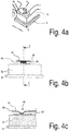
- FIGS. 4a to 4c illustrate how, for example, the spring arm 16 of the fixing element 11 engages the primary headlight optics 12.
- the FIG. 4a is a section of the perspective view of FIG. 2
- the FIG. 4b shows the spring arm 16 and a portion of the primary headlamp optics 12 and the board 5, seen along an axis of the spring arm 16.
- Die FIG. 4b shows a cross section along the section line CC, which in the FIG. 4b is shown.
- the primary headlight optics 12 has a projection 40 on which the spring arm 16 engages in an area where it has a bend 45 (shown in FIG Figure 4c ) having.
- the projection 40 causes the lateral ends 42, 43 of the spring arm 16 in the region of the bend 45 does not come into contact with the surface of the primary headlight optics 12.
- a distal end 44 of the spring arm 16 does not come into contact with the surface of the primary headlamp system 12.
- the projection 40 has an elongate shape and extends substantially parallel to the guide track 22 (shown in FIG. 2 ).
- An axis of the profile of the bend 45 of the spring arm 16 extends substantially perpendicular to the axis of the projection 40.
- the force application points in the spring arms 17 and 18 are designed accordingly.
- the board reset component 23 attacks the board reset component 23 on the projection 46 of the primary headlight optics 12.
- the board reset component 23 has a bend through which an edge 47 of the return component of the primary Headlamp optics 12 is spaced. The opposite edge protrudes beyond an edge of the primary headlight optics 12.
- the spring arms are designed so that for each of the spring arms, an edge of the respective spring arm is spaced from a surface region of the spring arm, via which the spring force of the spring arm is transmitted.
- FIG. 5 shows components of a headlamp system 1a according to a second embodiment.
- the headlamp system 1 a has components that belong to components of the headlight system 1 of the first embodiment (shown in FIGS FIGS. 1 to 4 ) are analog. Therefore, these components are provided with similar reference numerals but having the a sign a .
- the headlamp system 1a of the second embodiment is configured such that the board unit 2a is movable in a plane parallel to the heat contact surface of the heat sink 3a in two dimensions. As in the headlamp system 1 of the first embodiment, the board unit 2a is thereby pressed against the thermal contact surface with the aid of a fixing element 11a.
- the spring arms 16a, 17a, and 18a engage the primary headlight optics 12a.
- the primary headlamp optics 12a no reflectors, but an auxiliary lens 35a.
- the headlight system 1a has a guide element 24a, of which in the FIG. 5 two sections can be seen, which protrude on both sides under the fixing element 11a.
- the board unit 2a is mounted on the guide element 24a one-dimensionally movable accordingly a first axis 29a. It is also conceivable that additionally or alternatively, the primary headlight optics 12a is mounted on the guide element 24a in a one-dimensionally movable manner.
- the guide member 24a is mounted on the heat sink 3a one-dimensionally movable according to a second axis 30a.
- the heat sink 3a on the guide grooves 51a and 26a.
- the guide grooves 51a and 26a serve to guide two guide pins 27a and 28a which are formed on the guide member 24a and which are oriented along the second axis 30a.
- the guide of the board unit 2a on the guide member 24a is carried out in a similar manner as in the first embodiment, the leadership of the board unit 2 (shown in the FIG. 1 ) by the heat sink 3.
- the guide member 24a has projections (not shown), which engage in corresponding recesses of the board 5a.
- the guidance of the board unit 2a on the guide element 24a, as well as the guidance of the guide element 24a on the heat sink 3a represents a cross guide for movements parallel to the plane of the thermal contact surface, which provides the two-dimensional guidance of the board unit 2a relative to the heat sink 3a.
- the headlight system 1a For adjusting the position of the board unit 2a along the first axis 29a of the two-dimensional guide, the headlight system 1a comprises a board actuator (not shown in FIGS FIG. 5 ) which engages an angled portion 25a of the board 5a.
- the board actuator of the headlamp system 1a of the second embodiment is formed as a set screw, which is arranged in a threaded bushing 20a.
- a board reset component 23a which is designed as a spring arm.
- the board reset component 23a is integrally formed with the fixing member 11a.
- the headlamp system 1a on a guide element actuator 55a which is formed in an analogous manner as the board actuator.
- the guide member actuator 55a hidden by the guide member 24a and indicated schematically by a circle.
- the headlight system 1a has a guide element restoring component 32a, which is designed as a spring arm.
- the guide member return component 32a is formed integrally with the fixing member 11a.
- a free end portion of the spring arm of the guide member return component 32a is supported on a projection 34a which protrudes from and is rigidly connected to the heat sink 3a or integrally formed with the heat sink 3a.
- the one-piece design of the board reset component 23a and the guide element return component 32a with the fixing element 11a causes a simplification of the assembly, since all three components can be mounted simultaneously by fixing with the fixing screws 13a - 15a, 33a and 52a.
- the Guide element return component 32a and / or the board return component 23a is formed separately from the fixing element 11a.
- Seen in a direction perpendicular to the guide plane extends between the guide pins 27a and 28a, the guide member 24a between the board unit 2a and the primary headlight optics 12a, and / or between the primary headlight optics 12a and the fixing member 11a.
- the guide element 24a extends between the board unit 2a and the heat sink 3a.
- thermal contact between the board unit 2a and the heat sink 3a is thereby reduced.
- improved heat transfer between the board 5a and the heat sink 3a can be obtained by the arrangement of the force application points for the board actuator 19a (force application point P in FIG FIG. 5 ), for the board return component 23a (force application point Q ), for the guide element actuator 55a (force application point R) and / or for the guide element return component 32a (force application point S).
- a projection plane Projected onto a projection plane, which runs parallel to the thermal contact surface 10 and which therefore in the FIG. 5 oriented parallel to the paper plane, define the point of application Q , at which the board return component 23a attacks, as well as the force application point P , at which the board actuator 19a attacks, a common straight line 53a, on which both force application points P, Q are arranged.
- the orientation of the straight line 53a is not always exactly aligned along the first axis 29a, but depends on the Position of the guide member 24 relative to the heat sink 3 along the second axis 30 a from.
- the headlamp system 1a is formed so that in this projection, an angle ⁇ between the straight line 53a and the first axis 29a remains low.
- the angle ⁇ is less than 20 degrees or less than 10 degrees or less than 5 degrees.
- the force application points P and Q may be arranged opposite or substantially opposite one another relative to the light source 4a.
- the force application point S at which the guide element return component 32a engages to generate the counterforce to the actuating force of the guide element actuator 55a (in particular on the projection 37a of the guide element 24) and the force application point R , on which the guide element actuator 55a engages a common straight line 54a, on which both force application points R, S are arranged.
- the headlight system can be designed such that in this projection the angle ⁇ (shown in FIG. 5 ) between the straight line 54a and the second axis 30a is less than 20 degrees, less than 10 degrees, or less than 5 degrees.
- the straight line 54a may be aligned along the second axis.
- the force application points R and S may be arranged opposite or substantially opposite one another relative to the light source 4a.
- the primary headlight optics 12, 12a and the board 5, 5a respectively protected by the fixing element 11, 11a from light, which incident through the secondary headlight optics 8, 8a from the outside to the primary headlight optics 12, 12a and on the board 5,5a ,
- this incidence of light leads to focused light spots on the primary headlamp optics 12, 12a, which reduce the life of the primary headlamp optics 12, 12a and components of the board 5, 5a.
- a headlight system 1, 1a which provides an adjustability of the board unit 2, 2a and the primary headlight optics 12, 12a, while at the same time provides protection for the primary headlight optics 12, 12a from external light.
Landscapes
- Engineering & Computer Science (AREA)
- General Engineering & Computer Science (AREA)
- Non-Portable Lighting Devices Or Systems Thereof (AREA)
- Arrangement Of Elements, Cooling, Sealing, Or The Like Of Lighting Devices (AREA)
- Lighting Device Outwards From Vehicle And Optical Signal (AREA)
Applications Claiming Priority (1)
| Application Number | Priority Date | Filing Date | Title |
|---|---|---|---|
| DE102017115001.3A DE102017115001A1 (de) | 2017-07-05 | 2017-07-05 | Justierbares Scheinwerfersystem |
Publications (2)
| Publication Number | Publication Date |
|---|---|
| EP3425265A1 true EP3425265A1 (fr) | 2019-01-09 |
| EP3425265B1 EP3425265B1 (fr) | 2022-01-12 |
Family
ID=62712771
Family Applications (1)
| Application Number | Title | Priority Date | Filing Date |
|---|---|---|---|
| EP18177430.8A Active EP3425265B1 (fr) | 2017-07-05 | 2018-06-13 | Phare ajustable |
Country Status (2)
| Country | Link |
|---|---|
| EP (1) | EP3425265B1 (fr) |
| DE (1) | DE102017115001A1 (fr) |
Cited By (3)
| Publication number | Priority date | Publication date | Assignee | Title |
|---|---|---|---|---|
| WO2021237961A1 (fr) * | 2020-05-26 | 2021-12-02 | 华域视觉科技(上海)有限公司 | Mécanisme de gradation, module de phare de véhicule, phare de véhicule, et véhicule |
| US11970107B2 (en) | 2020-05-26 | 2024-04-30 | Hasco Vision Technology Co., Ltd. | Dimming mechanism, vehicle lamp module, vehicle lamp, and vehicle |
| DE102024128226A1 (de) | 2024-09-30 | 2026-04-02 | Marelli Germany Gmbh | Verfahren zur Justage von Lichtmodulen einer Lichtmodul-Baugruppe relativ zueinander |
Citations (5)
| Publication number | Priority date | Publication date | Assignee | Title |
|---|---|---|---|---|
| US20090303726A1 (en) * | 2008-06-04 | 2009-12-10 | Hella Kgaa Hueck & Co | Led lens mounting device |
| WO2014134649A1 (fr) * | 2013-03-07 | 2014-09-12 | Zizala Lichtsysteme Gmbh | Dispositif d'éclairage pour un phare de véhicule |
| US20150308652A1 (en) * | 2012-11-30 | 2015-10-29 | Valeo lluminacion | Motor vehicle lighting and/or signalling device |
| FR3029607A1 (fr) * | 2014-12-08 | 2016-06-10 | Valeo Vision | Couplage thermique avec matiere fluide, pateuse ou granulaire pour source lumineuse mobile |
| WO2016156463A1 (fr) * | 2015-03-31 | 2016-10-06 | Koninklijke Philips N.V. | Module d'éclairage à del comprenant un dissipateur thermique et procédé de remplacement d'un module à del |
-
2017
- 2017-07-05 DE DE102017115001.3A patent/DE102017115001A1/de not_active Withdrawn
-
2018
- 2018-06-13 EP EP18177430.8A patent/EP3425265B1/fr active Active
Patent Citations (5)
| Publication number | Priority date | Publication date | Assignee | Title |
|---|---|---|---|---|
| US20090303726A1 (en) * | 2008-06-04 | 2009-12-10 | Hella Kgaa Hueck & Co | Led lens mounting device |
| US20150308652A1 (en) * | 2012-11-30 | 2015-10-29 | Valeo lluminacion | Motor vehicle lighting and/or signalling device |
| WO2014134649A1 (fr) * | 2013-03-07 | 2014-09-12 | Zizala Lichtsysteme Gmbh | Dispositif d'éclairage pour un phare de véhicule |
| FR3029607A1 (fr) * | 2014-12-08 | 2016-06-10 | Valeo Vision | Couplage thermique avec matiere fluide, pateuse ou granulaire pour source lumineuse mobile |
| WO2016156463A1 (fr) * | 2015-03-31 | 2016-10-06 | Koninklijke Philips N.V. | Module d'éclairage à del comprenant un dissipateur thermique et procédé de remplacement d'un module à del |
Cited By (4)
| Publication number | Priority date | Publication date | Assignee | Title |
|---|---|---|---|---|
| WO2021237961A1 (fr) * | 2020-05-26 | 2021-12-02 | 华域视觉科技(上海)有限公司 | Mécanisme de gradation, module de phare de véhicule, phare de véhicule, et véhicule |
| US11970107B2 (en) | 2020-05-26 | 2024-04-30 | Hasco Vision Technology Co., Ltd. | Dimming mechanism, vehicle lamp module, vehicle lamp, and vehicle |
| US12097798B2 (en) | 2020-05-26 | 2024-09-24 | Hasco Vision Technology Co., Ltd. | Dimming mechanism, vehicle lamp module, vehicle lamp, and vehicle |
| DE102024128226A1 (de) | 2024-09-30 | 2026-04-02 | Marelli Germany Gmbh | Verfahren zur Justage von Lichtmodulen einer Lichtmodul-Baugruppe relativ zueinander |
Also Published As
| Publication number | Publication date |
|---|---|
| EP3425265B1 (fr) | 2022-01-12 |
| DE102017115001A1 (de) | 2019-01-10 |
Similar Documents
| Publication | Publication Date | Title |
|---|---|---|
| DE102008036192B4 (de) | Kraftfahrzeugbeleuchtungseinrichtung | |
| EP2314912B1 (fr) | Lampe à DEL dotée d'un angle de rayonnement réglable en continu | |
| EP2375128B1 (fr) | Luminaire dotée de DEL et de lentilles attribuées aux DEL | |
| EP2627944B1 (fr) | Phare de véhicule à led | |
| DE102004062989A1 (de) | Beleuchtungseinrichtung mit mindestens einer Leuchtdiode und Fahrzeugscheinwerfer | |
| EP3638944B1 (fr) | Phare de véhicule automobile | |
| EP3428512B1 (fr) | Module d'éclairage d'un phare de véhicule automobile et phare de véhicule automobile doté d'un tel module d'éclairage | |
| DE102018216212B4 (de) | Fahrzeugleuchte | |
| EP3425265B1 (fr) | Phare ajustable | |
| EP3096980B1 (fr) | Unité laser pour phare de véhicule | |
| DE102011051050A1 (de) | Lichteinheit für einen Scheinwerfer eines Fahrzeugs | |
| AT17812U1 (de) | Leuchtvorrichtung für ein Kraftfahrzeug mit einem Leuchtmodul | |
| DE102017110877A1 (de) | Lichtmodul eines Kraftfahrzeugscheinwerfers und Kraftfahrzeugscheinwerfer mit einem solchen Lichtmodul | |
| EP3165818B2 (fr) | Éclairage intérieur ou extérieur, en particulier réverbère comprenant une lentille à forme libre pouvant être décalée | |
| DE102016105730B4 (de) | Vorrichtung und Verfahren zum Reduzieren von Rändern des Lichtbilds eines Scheinwerfers und Scheinwerfer mit der Vorrichtung | |
| DE102012103631B4 (de) | Lichtmodul für den Scheinwerfer eines Fahrzeuges | |
| EP3625500B1 (fr) | Module lumineux d'un projecteur de véhicule à moteur et projecteur de véhicule à moteur comprenant ledit module lumineux | |
| DE102022108281B4 (de) | Lichtmodul und Kraftfahrzeugbeleuchtungseinrichtung mit einem solchen Lichtmodul | |
| DE102013213868B4 (de) | Beleuchtungsvorrichtung für ein Kraftfahrzeug | |
| DE102022113326A1 (de) | Lichtmodul eines Kraftfahrzeugscheinwerfers und Kraftfahrzeugscheinwerfer mit einem solchen Lichtmodul | |
| EP3311211B1 (fr) | Unité laser dotée d'un dispositif de réglage de collimateur | |
| DE102011119382B4 (de) | Beleuchtungsvorrichtung für ein Kraftfahrzeug mit einer Lichtscheibe, an der mindestens ein Träger für LEDs in Fortsetzung von Kühlergrill-Lamellen nach außen absteht | |
| EP3064827B1 (fr) | Arrangement d'un montage d'un module led sur une surface d'un corps de refroidissement et montage led | |
| EP2320132B1 (fr) | Phare de véhicule | |
| DE102013107575B4 (de) | Vorrichtung zur Justage eines Optikelements |
Legal Events
| Date | Code | Title | Description |
|---|---|---|---|
| PUAI | Public reference made under article 153(3) epc to a published international application that has entered the european phase |
Free format text: ORIGINAL CODE: 0009012 |
|
| STAA | Information on the status of an ep patent application or granted ep patent |
Free format text: STATUS: THE APPLICATION HAS BEEN PUBLISHED |
|
| AK | Designated contracting states |
Kind code of ref document: A1 Designated state(s): AL AT BE BG CH CY CZ DE DK EE ES FI FR GB GR HR HU IE IS IT LI LT LU LV MC MK MT NL NO PL PT RO RS SE SI SK SM TR |
|
| AX | Request for extension of the european patent |
Extension state: BA ME |
|
| STAA | Information on the status of an ep patent application or granted ep patent |
Free format text: STATUS: REQUEST FOR EXAMINATION WAS MADE |
|
| 17P | Request for examination filed |
Effective date: 20190708 |
|
| RBV | Designated contracting states (corrected) |
Designated state(s): AL AT BE BG CH CY CZ DE DK EE ES FI FR GB GR HR HU IE IS IT LI LT LU LV MC MK MT NL NO PL PT RO RS SE SI SK SM TR |
|
| RAP1 | Party data changed (applicant data changed or rights of an application transferred) |
Owner name: MARELLI AUTOMOTIVE LIGHTING REUTLINGEN (GERMANY) GMBH |
|
| STAA | Information on the status of an ep patent application or granted ep patent |
Free format text: STATUS: EXAMINATION IS IN PROGRESS |
|
| 17Q | First examination report despatched |
Effective date: 20210304 |
|
| GRAP | Despatch of communication of intention to grant a patent |
Free format text: ORIGINAL CODE: EPIDOSNIGR1 |
|
| STAA | Information on the status of an ep patent application or granted ep patent |
Free format text: STATUS: GRANT OF PATENT IS INTENDED |
|
| INTG | Intention to grant announced |
Effective date: 20211020 |
|
| GRAS | Grant fee paid |
Free format text: ORIGINAL CODE: EPIDOSNIGR3 |
|
| GRAA | (expected) grant |
Free format text: ORIGINAL CODE: 0009210 |
|
| STAA | Information on the status of an ep patent application or granted ep patent |
Free format text: STATUS: THE PATENT HAS BEEN GRANTED |
|
| AK | Designated contracting states |
Kind code of ref document: B1 Designated state(s): AL AT BE BG CH CY CZ DE DK EE ES FI FR GB GR HR HU IE IS IT LI LT LU LV MC MK MT NL NO PL PT RO RS SE SI SK SM TR |
|
| REG | Reference to a national code |
Ref country code: GB Ref legal event code: FG4D Free format text: NOT ENGLISH |
|
| REG | Reference to a national code |
Ref country code: CH Ref legal event code: EP |
|
| REG | Reference to a national code |
Ref country code: DE Ref legal event code: R096 Ref document number: 502018008483 Country of ref document: DE |
|
| REG | Reference to a national code |
Ref country code: IE Ref legal event code: FG4D Free format text: LANGUAGE OF EP DOCUMENT: GERMAN |
|
| REG | Reference to a national code |
Ref country code: AT Ref legal event code: REF Ref document number: 1462619 Country of ref document: AT Kind code of ref document: T Effective date: 20220215 |
|
| REG | Reference to a national code |
Ref country code: LT Ref legal event code: MG9D |
|
| REG | Reference to a national code |
Ref country code: NL Ref legal event code: MP Effective date: 20220112 |
|
| PG25 | Lapsed in a contracting state [announced via postgrant information from national office to epo] |
Ref country code: NL Free format text: LAPSE BECAUSE OF FAILURE TO SUBMIT A TRANSLATION OF THE DESCRIPTION OR TO PAY THE FEE WITHIN THE PRESCRIBED TIME-LIMIT Effective date: 20220112 |
|
| PG25 | Lapsed in a contracting state [announced via postgrant information from national office to epo] |
Ref country code: SE Free format text: LAPSE BECAUSE OF FAILURE TO SUBMIT A TRANSLATION OF THE DESCRIPTION OR TO PAY THE FEE WITHIN THE PRESCRIBED TIME-LIMIT Effective date: 20220112 Ref country code: RS Free format text: LAPSE BECAUSE OF FAILURE TO SUBMIT A TRANSLATION OF THE DESCRIPTION OR TO PAY THE FEE WITHIN THE PRESCRIBED TIME-LIMIT Effective date: 20220112 Ref country code: PT Free format text: LAPSE BECAUSE OF FAILURE TO SUBMIT A TRANSLATION OF THE DESCRIPTION OR TO PAY THE FEE WITHIN THE PRESCRIBED TIME-LIMIT Effective date: 20220512 Ref country code: NO Free format text: LAPSE BECAUSE OF FAILURE TO SUBMIT A TRANSLATION OF THE DESCRIPTION OR TO PAY THE FEE WITHIN THE PRESCRIBED TIME-LIMIT Effective date: 20220412 Ref country code: LT Free format text: LAPSE BECAUSE OF FAILURE TO SUBMIT A TRANSLATION OF THE DESCRIPTION OR TO PAY THE FEE WITHIN THE PRESCRIBED TIME-LIMIT Effective date: 20220112 Ref country code: HR Free format text: LAPSE BECAUSE OF FAILURE TO SUBMIT A TRANSLATION OF THE DESCRIPTION OR TO PAY THE FEE WITHIN THE PRESCRIBED TIME-LIMIT Effective date: 20220112 Ref country code: ES Free format text: LAPSE BECAUSE OF FAILURE TO SUBMIT A TRANSLATION OF THE DESCRIPTION OR TO PAY THE FEE WITHIN THE PRESCRIBED TIME-LIMIT Effective date: 20220112 Ref country code: BG Free format text: LAPSE BECAUSE OF FAILURE TO SUBMIT A TRANSLATION OF THE DESCRIPTION OR TO PAY THE FEE WITHIN THE PRESCRIBED TIME-LIMIT Effective date: 20220412 |
|
| PG25 | Lapsed in a contracting state [announced via postgrant information from national office to epo] |
Ref country code: PL Free format text: LAPSE BECAUSE OF FAILURE TO SUBMIT A TRANSLATION OF THE DESCRIPTION OR TO PAY THE FEE WITHIN THE PRESCRIBED TIME-LIMIT Effective date: 20220112 Ref country code: LV Free format text: LAPSE BECAUSE OF FAILURE TO SUBMIT A TRANSLATION OF THE DESCRIPTION OR TO PAY THE FEE WITHIN THE PRESCRIBED TIME-LIMIT Effective date: 20220112 Ref country code: GR Free format text: LAPSE BECAUSE OF FAILURE TO SUBMIT A TRANSLATION OF THE DESCRIPTION OR TO PAY THE FEE WITHIN THE PRESCRIBED TIME-LIMIT Effective date: 20220413 Ref country code: FI Free format text: LAPSE BECAUSE OF FAILURE TO SUBMIT A TRANSLATION OF THE DESCRIPTION OR TO PAY THE FEE WITHIN THE PRESCRIBED TIME-LIMIT Effective date: 20220112 |
|
| PG25 | Lapsed in a contracting state [announced via postgrant information from national office to epo] |
Ref country code: IS Free format text: LAPSE BECAUSE OF FAILURE TO SUBMIT A TRANSLATION OF THE DESCRIPTION OR TO PAY THE FEE WITHIN THE PRESCRIBED TIME-LIMIT Effective date: 20220512 |
|
| REG | Reference to a national code |
Ref country code: DE Ref legal event code: R097 Ref document number: 502018008483 Country of ref document: DE |
|
| PG25 | Lapsed in a contracting state [announced via postgrant information from national office to epo] |
Ref country code: SM Free format text: LAPSE BECAUSE OF FAILURE TO SUBMIT A TRANSLATION OF THE DESCRIPTION OR TO PAY THE FEE WITHIN THE PRESCRIBED TIME-LIMIT Effective date: 20220112 Ref country code: SK Free format text: LAPSE BECAUSE OF FAILURE TO SUBMIT A TRANSLATION OF THE DESCRIPTION OR TO PAY THE FEE WITHIN THE PRESCRIBED TIME-LIMIT Effective date: 20220112 Ref country code: RO Free format text: LAPSE BECAUSE OF FAILURE TO SUBMIT A TRANSLATION OF THE DESCRIPTION OR TO PAY THE FEE WITHIN THE PRESCRIBED TIME-LIMIT Effective date: 20220112 Ref country code: EE Free format text: LAPSE BECAUSE OF FAILURE TO SUBMIT A TRANSLATION OF THE DESCRIPTION OR TO PAY THE FEE WITHIN THE PRESCRIBED TIME-LIMIT Effective date: 20220112 Ref country code: DK Free format text: LAPSE BECAUSE OF FAILURE TO SUBMIT A TRANSLATION OF THE DESCRIPTION OR TO PAY THE FEE WITHIN THE PRESCRIBED TIME-LIMIT Effective date: 20220112 Ref country code: CZ Free format text: LAPSE BECAUSE OF FAILURE TO SUBMIT A TRANSLATION OF THE DESCRIPTION OR TO PAY THE FEE WITHIN THE PRESCRIBED TIME-LIMIT Effective date: 20220112 |
|
| PLBE | No opposition filed within time limit |
Free format text: ORIGINAL CODE: 0009261 |
|
| STAA | Information on the status of an ep patent application or granted ep patent |
Free format text: STATUS: NO OPPOSITION FILED WITHIN TIME LIMIT |
|
| PG25 | Lapsed in a contracting state [announced via postgrant information from national office to epo] |
Ref country code: AL Free format text: LAPSE BECAUSE OF FAILURE TO SUBMIT A TRANSLATION OF THE DESCRIPTION OR TO PAY THE FEE WITHIN THE PRESCRIBED TIME-LIMIT Effective date: 20220112 |
|
| 26N | No opposition filed |
Effective date: 20221013 |
|
| PG25 | Lapsed in a contracting state [announced via postgrant information from national office to epo] |
Ref country code: MC Free format text: LAPSE BECAUSE OF FAILURE TO SUBMIT A TRANSLATION OF THE DESCRIPTION OR TO PAY THE FEE WITHIN THE PRESCRIBED TIME-LIMIT Effective date: 20220112 |
|
| REG | Reference to a national code |
Ref country code: CH Ref legal event code: PL |
|
| REG | Reference to a national code |
Ref country code: BE Ref legal event code: MM Effective date: 20220630 |
|
| PG25 | Lapsed in a contracting state [announced via postgrant information from national office to epo] |
Ref country code: SI Free format text: LAPSE BECAUSE OF FAILURE TO SUBMIT A TRANSLATION OF THE DESCRIPTION OR TO PAY THE FEE WITHIN THE PRESCRIBED TIME-LIMIT Effective date: 20220112 |
|
| GBPC | Gb: european patent ceased through non-payment of renewal fee |
Effective date: 20220613 |
|
| PG25 | Lapsed in a contracting state [announced via postgrant information from national office to epo] |
Ref country code: LU Free format text: LAPSE BECAUSE OF NON-PAYMENT OF DUE FEES Effective date: 20220613 Ref country code: LI Free format text: LAPSE BECAUSE OF NON-PAYMENT OF DUE FEES Effective date: 20220630 Ref country code: IE Free format text: LAPSE BECAUSE OF NON-PAYMENT OF DUE FEES Effective date: 20220613 Ref country code: FR Free format text: LAPSE BECAUSE OF NON-PAYMENT OF DUE FEES Effective date: 20220630 Ref country code: CH Free format text: LAPSE BECAUSE OF NON-PAYMENT OF DUE FEES Effective date: 20220630 |
|
| PG25 | Lapsed in a contracting state [announced via postgrant information from national office to epo] |
Ref country code: GB Free format text: LAPSE BECAUSE OF NON-PAYMENT OF DUE FEES Effective date: 20220613 Ref country code: BE Free format text: LAPSE BECAUSE OF NON-PAYMENT OF DUE FEES Effective date: 20220630 |
|
| PG25 | Lapsed in a contracting state [announced via postgrant information from national office to epo] |
Ref country code: IT Free format text: LAPSE BECAUSE OF FAILURE TO SUBMIT A TRANSLATION OF THE DESCRIPTION OR TO PAY THE FEE WITHIN THE PRESCRIBED TIME-LIMIT Effective date: 20220112 |
|
| PG25 | Lapsed in a contracting state [announced via postgrant information from national office to epo] |
Ref country code: HU Free format text: LAPSE BECAUSE OF FAILURE TO SUBMIT A TRANSLATION OF THE DESCRIPTION OR TO PAY THE FEE WITHIN THE PRESCRIBED TIME-LIMIT; INVALID AB INITIO Effective date: 20180613 |
|
| PG25 | Lapsed in a contracting state [announced via postgrant information from national office to epo] |
Ref country code: MK Free format text: LAPSE BECAUSE OF FAILURE TO SUBMIT A TRANSLATION OF THE DESCRIPTION OR TO PAY THE FEE WITHIN THE PRESCRIBED TIME-LIMIT Effective date: 20220112 Ref country code: CY Free format text: LAPSE BECAUSE OF FAILURE TO SUBMIT A TRANSLATION OF THE DESCRIPTION OR TO PAY THE FEE WITHIN THE PRESCRIBED TIME-LIMIT Effective date: 20220112 |
|
| REG | Reference to a national code |
Ref country code: AT Ref legal event code: MM01 Ref document number: 1462619 Country of ref document: AT Kind code of ref document: T Effective date: 20230613 |
|
| PG25 | Lapsed in a contracting state [announced via postgrant information from national office to epo] |
Ref country code: MT Free format text: LAPSE BECAUSE OF FAILURE TO SUBMIT A TRANSLATION OF THE DESCRIPTION OR TO PAY THE FEE WITHIN THE PRESCRIBED TIME-LIMIT Effective date: 20220112 |
|
| PG25 | Lapsed in a contracting state [announced via postgrant information from national office to epo] |
Ref country code: AT Free format text: LAPSE BECAUSE OF NON-PAYMENT OF DUE FEES Effective date: 20230613 |
|
| PG25 | Lapsed in a contracting state [announced via postgrant information from national office to epo] |
Ref country code: AT Free format text: LAPSE BECAUSE OF NON-PAYMENT OF DUE FEES Effective date: 20230613 |
|
| PGFP | Annual fee paid to national office [announced via postgrant information from national office to epo] |
Ref country code: DE Payment date: 20250520 Year of fee payment: 8 |
|
| PG25 | Lapsed in a contracting state [announced via postgrant information from national office to epo] |
Ref country code: TR Free format text: LAPSE BECAUSE OF FAILURE TO SUBMIT A TRANSLATION OF THE DESCRIPTION OR TO PAY THE FEE WITHIN THE PRESCRIBED TIME-LIMIT Effective date: 20220112 |
|
| REG | Reference to a national code |
Ref country code: DE Ref legal event code: R081 Ref document number: 502018008483 Country of ref document: DE Owner name: MARELLI GERMANY GMBH, DE Free format text: FORMER OWNER: MARELLI AUTOMOTIVE LIGHTING REUTLINGEN (GERMANY) GMBH, 72762 REUTLINGEN, DE |
|
| PGFP | Annual fee paid to national office [announced via postgrant information from national office to epo] |
Ref country code: AT Payment date: 20260410 Year of fee payment: 5 |