EP3426422B1 - Verfahren zur automatisierten robotischen herstellung von willkürlich geformten metallischen maschen mit variabler dichte - Google Patents
Verfahren zur automatisierten robotischen herstellung von willkürlich geformten metallischen maschen mit variabler dichte Download PDFInfo
- Publication number
- EP3426422B1 EP3426422B1 EP17715403.6A EP17715403A EP3426422B1 EP 3426422 B1 EP3426422 B1 EP 3426422B1 EP 17715403 A EP17715403 A EP 17715403A EP 3426422 B1 EP3426422 B1 EP 3426422B1
- Authority
- EP
- European Patent Office
- Prior art keywords
- dimensional
- wires
- effector
- autonomous mobile
- self
- Prior art date
- Legal status (The legal status is an assumption and is not a legal conclusion. Google has not performed a legal analysis and makes no representation as to the accuracy of the status listed.)
- Active
Links
Images





Classifications
-
- B—PERFORMING OPERATIONS; TRANSPORTING
- B25—HAND TOOLS; PORTABLE POWER-DRIVEN TOOLS; MANIPULATORS
- B25J—MANIPULATORS; CHAMBERS PROVIDED WITH MANIPULATION DEVICES
- B25J9/00—Program-controlled manipulators
- B25J9/16—Program controls
- B25J9/1656—Program controls characterised by programming, planning systems for manipulators
- B25J9/1669—Program controls characterised by programming, planning systems for manipulators characterised by special application, e.g. multi-arm co-operation, assembly, grasping
-
- B—PERFORMING OPERATIONS; TRANSPORTING
- B21—MECHANICAL METAL-WORKING WITHOUT ESSENTIALLY REMOVING MATERIAL; PUNCHING METAL
- B21F—WORKING OR PROCESSING OF METAL WIRE
- B21F27/00—Making wire network, i.e. wire nets
- B21F27/08—Making wire network, i.e. wire nets with additional connecting elements or material at crossings
- B21F27/10—Making wire network, i.e. wire nets with additional connecting elements or material at crossings with soldered or welded crossings
-
- B—PERFORMING OPERATIONS; TRANSPORTING
- B21—MECHANICAL METAL-WORKING WITHOUT ESSENTIALLY REMOVING MATERIAL; PUNCHING METAL
- B21F—WORKING OR PROCESSING OF METAL WIRE
- B21F27/00—Making wire network, i.e. wire nets
- B21F27/12—Making special types or portions of network by methods or means specially adapted therefor
-
- B—PERFORMING OPERATIONS; TRANSPORTING
- B25—HAND TOOLS; PORTABLE POWER-DRIVEN TOOLS; MANIPULATORS
- B25J—MANIPULATORS; CHAMBERS PROVIDED WITH MANIPULATION DEVICES
- B25J11/00—Manipulators not otherwise provided for
- B25J11/005—Manipulators for mechanical processing tasks
-
- B—PERFORMING OPERATIONS; TRANSPORTING
- B25—HAND TOOLS; PORTABLE POWER-DRIVEN TOOLS; MANIPULATORS
- B25J—MANIPULATORS; CHAMBERS PROVIDED WITH MANIPULATION DEVICES
- B25J9/00—Program-controlled manipulators
- B25J9/16—Program controls
- B25J9/1615—Program controls characterised by special kind of manipulator, e.g. planar, scara, gantry, cantilever, space, closed chain, passive/active joints and tendon driven manipulators
- B25J9/162—Mobile manipulator, movable base with manipulator arm mounted on it
-
- B—PERFORMING OPERATIONS; TRANSPORTING
- B25—HAND TOOLS; PORTABLE POWER-DRIVEN TOOLS; MANIPULATORS
- B25J—MANIPULATORS; CHAMBERS PROVIDED WITH MANIPULATION DEVICES
- B25J9/00—Program-controlled manipulators
- B25J9/16—Program controls
- B25J9/1656—Program controls characterised by programming, planning systems for manipulators
- B25J9/1671—Program controls characterised by programming, planning systems for manipulators characterised by simulation, either to verify existing program or to create and verify new program, CAD/CAM oriented, graphic oriented programming systems
-
- B—PERFORMING OPERATIONS; TRANSPORTING
- B25—HAND TOOLS; PORTABLE POWER-DRIVEN TOOLS; MANIPULATORS
- B25J—MANIPULATORS; CHAMBERS PROVIDED WITH MANIPULATION DEVICES
- B25J9/00—Program-controlled manipulators
- B25J9/16—Program controls
- B25J9/1679—Program controls characterised by the tasks executed
- B25J9/1687—Assembly, peg and hole, palletising, straight line, weaving pattern movement
Definitions
- This invention describes a method for the fabrication of threedimensional meshes, in particular freeform, volumetric metallic meshes with variable density. Specific applications include concrete formwork and reinforcement but can find use in other construction purposes as well.
- Metal meshes are used for a wide variety of applications, ranging from lightweight structural components to reinforcements of composite building structures or scaffolding and substructures. These meshes mainly follow simple rectangular or single curved geometries as currently metal meshes can only be produced economically as planar two-dimensional mats with equally spaced cell sizes. In order to meet the demand for complex construction geometries and to therefore enable the fabrication of non-standard, structurally optimized steel reinforced concrete structures, three-dimensionally shaped metal meshes are required. To create three-dimensional metal meshes out of a continuous metal wire in an automated manner, it is required to integrate metal wire straightening, bending, feeding, cutting and welding within a digitally-controlled process that allows for a) variable mesh geometries and b) automated manufacturing.
- the second strategy to manufacture three-dimensional mesh structures starts exactly at this point.
- Two flat steel mats or steel meshes are connected by spacers at a certain distance in order to obtain a three-dimensional mesh. Since the automatic production of the initial mesh faces is usually limited to planar surfaces, also the resulting meshes are constrained to planar geometries, such as, for example, volumetric sandwich meshes (see for example CN 1171709 C , "Productive method and apparatus for 3D cross-linked sandwich screen plate").
- WO 2015/034438 A1 forms the basis for the preamble of claim 1.
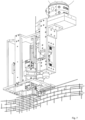
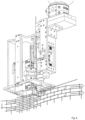
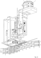
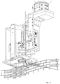
- An aspect of the present disclosure is a robotic setup including a custom multifunctional robotic end-effector that facilitates the digitally controlled fabrication of threedimensional metal meshes with locally and globally varying volume, curvature and cell size.
- a further aspect of the present disclosure is a digital process to produce three dimensional metallic meshes, of varying shapes and density, and the robotic setup which automates this digital process.
- the novelty of the invention not only lies in the robust integration of key subfunctionalities like wire straightening, feeding, bending, cutting and cross wire welding of the proposed method and setup into a single, robotically guided and digitally controlled endeffector mounted on a mobile robotic manipulator but also in the sequence in which they are executed.
- the machine is static and the building element moves through the machine, here preferably the building element remains static and the machine (robotic setup) moves in order to fabricate the structure.
- a further aspect of the present disclosure is a digital design and control process to robotically produce three-dimensional metallic meshes, of varying volume, shape and density, which allows a complete digital parameterization of a mesh geometry - including overall dimension, shape and global/local geometric manipulation - and to export specific design data sets and to directly transfer it to a robotic control system.
- this allows to automatically (design and) fabrication variable, non-standard three-dimensional meshes, which can be used in particular as concrete reinforcements or lost formwork (or as a combination of these two).
- the mobile manufacturing device comprises a specialised end-effector which is adapted to move along a three-dimensional structure to be produced and is adapted to carry out at least some of the steps of the method for producing three-dimensional, highly variable lattice or mesh structures according to the invention.
- the present invention relates to a method of producing three-dimensional, highly variable lattice or mesh structures as defined in appended claim 1.
- a custom control software Based on a parametric three-dimensional model of the mesh, for which its local and global curvature, its height and length can be varied, a custom control software generates motion commands for the robotic setup which comprises of a mobile manipulator and a specialized end-effector.
- the mobile manipulator includes an autonomous mobile base, which can selflocalize in its environment with the help of on-board sensors. Further, the mobile manipulator includes an robotic arm together with a specialized self-contained end-effector, which is mounted to the robotic arm.
- the self-contained end-effector can include additional sensing, both for feedback from cutting and welding as well as to provide additional localization through for example, but not limited to cameras and lasers and inertial measurement units.
- the building element remains static and the machine (robotic setup) moves in order to fabricate the structure.
- This inversion achieved through the use of an autonomous mobile manipulator significantly increases the dimensions and articulation of geometries that can be fabricated and imposes fewer restrictions on the achievable size of the structure being built. Especially it allows for an in situ production and specialised geometric and structural adaptation of the meshes, even within constraints of a building shell.
- This digitally-controlled manufacturing of three-dimensional metal meshes comprises features which can be totally automated not only separately but also as a programmable sequence of operations.
- the present invention therefore describes a unique construction method and robotic setup (including the robotic end-effector), which provides a robust integration of all these features and which is totally automated.
- This advantage of total digitally-controlled automation not present in the state of art, enables significantly enhanced geometric freedom in determining, for example, overall dimension and volume as well as formal articulation and density of metal wire meshes. This also enables to achieve differentiation of a mesh geometry locally in order to adapt the structure's geometry locally in areas where stress concentration is higher due to external loads.
- the key advantage is the full automation of the process and the high flexibility with regards to non-standard geometries that can be produced without having to change the machine setup and or the overall design approach.
- This is possible through the aforementioned inversion of static machine and mobile building element.
- the machine setup had to change in order to accommodate varying building element geometries
- the mobile manipulator remains unaffected by the geometry of the building element due to the inherent high flexibility of the applied method and setup.
- this ability to mass customize building elements allows fabricating geometries which are tailored exactly towards their specific load case or purpose, which in turn allows for significant savings in material (such as for formwork, reinforcement or concrete filling).
- the invention can be used for other concrete construction systems. Additionally the method could be used for other structural applications that depend on geometric flexibility (for example volume and shape) without having to fill the mesh with concrete or other materials. Here the focus could potentially be on fences, cages, lightweight structures or other load-bearing structures and scaffoldings.
Landscapes
- Engineering & Computer Science (AREA)
- Mechanical Engineering (AREA)
- Robotics (AREA)
- Health & Medical Sciences (AREA)
- General Health & Medical Sciences (AREA)
- Orthopedic Medicine & Surgery (AREA)
- Manipulator (AREA)
- Numerical Control (AREA)
- Wire Processing (AREA)
Claims (2)
- Verfahren zur Herstellung von dreidimensionalen, hochvariablen Gitter- oder Netzstrukturen mittels einer mobilen Fertigungsvorrichtung, wobei die mobile Fertigungsvorrichtung geeignet ist, sich entlang einer herzustellenden dreidimensionalen Struktur zu bewegen, und wobei die mobile Fertigungsvorrichtung ein Mittel zur Erfassung ihrer Position relativ zu der herzustellenden dimensionalen Struktur aufweist, so dass die mobile Herstellungsvorrichtung in der Lage ist, die dreidimensionale Struktur als autonomer Roboter herzustellen, wobei die mobile Herstellungsvorrichtung auf einer zweidimensionalen Ebene bewegt wird und mittels ihres Endeffektors eine dreidimensionale Gitter- oder Netzstruktur herstellt, indem sie Drähte sowohl in horizontaler als auch in nicht-horizontaler Ausrichtung bereitstellt und eine Vielzahl dieser Drähte biegt und/oder verbindet, wobei das Verfahren die folgenden Schritte umfasst:Schritt 1: Ein autonomer mobiler Manipulator legt die Metalldrähte horizontal in definierten vertikalen Abständen und in vorgegebenen Längen im dreidimensionalen Raum ab;Schritt 2: der autonome Endeffektor des autonomen mobilen Manipulators biegt diese verlegten horizontalen Drähte aus Schritt 1 an vorgegebenen Punkten um vorgegebene Winkel;Schritt 3: Der eigenständige Endeffektor des autonomen mobilen Manipulators ergreift die Drähte und führt sie vertikal in diskreten Schritten mit unterschiedlichen Längen zu;Schritt 4: Steuerung einer räumlichen Anordnung der horizontalen Drähte aus Schritt 1 und der vertikalen Drähte aus Schritt 3 durch den mobilen Manipulator, die durch ein dreidimensionales parametrisches Modell vorgegeben ist;Schritt 5: der autonome Endeffektor des autonomen mobilen Manipulators bildet gekreuzte Drahtverbindungen, indem er die horizontalen Drähte aus Schritt 1 und die vertikalen Drähte aus Schritt 3 zusammenführt;Schritt 6: der eigenständige Endeffektor des autonomen mobilen Manipulators schweißt die gekreuzten Drahtverbindungen aus Schritt 5 zusammen, um gekreuzte Drahtverbindungsstellen zu bilden; undSchritt 7: der autonome Endeffektor des autonomen mobilen Manipulators schneidet die vertikalen Drähte aus Schritt 3 auf unterschiedliche Längen.
- Verfahren zur Herstellung dreidimensionaler Netz- oder Gitterstrukturen nach Anspruch 1, wobei zumindest einige der Schritte des Herstellungsprozesses digital gesteuert werden.
Applications Claiming Priority (2)
| Application Number | Priority Date | Filing Date | Title |
|---|---|---|---|
| EP16159663 | 2016-03-10 | ||
| PCT/EP2017/055639 WO2017153559A1 (en) | 2016-03-10 | 2017-03-10 | Digital method and automated robotic setup for producing variable-density and arbitrary shaped metallic meshes |
Publications (3)
| Publication Number | Publication Date |
|---|---|
| EP3426422A1 EP3426422A1 (de) | 2019-01-16 |
| EP3426422B1 true EP3426422B1 (de) | 2024-06-26 |
| EP3426422C0 EP3426422C0 (de) | 2024-06-26 |
Family
ID=55532161
Family Applications (1)
| Application Number | Title | Priority Date | Filing Date |
|---|---|---|---|
| EP17715403.6A Active EP3426422B1 (de) | 2016-03-10 | 2017-03-10 | Verfahren zur automatisierten robotischen herstellung von willkürlich geformten metallischen maschen mit variabler dichte |
Country Status (3)
| Country | Link |
|---|---|
| US (1) | US10946522B2 (de) |
| EP (1) | EP3426422B1 (de) |
| WO (1) | WO2017153559A1 (de) |
Families Citing this family (6)
| Publication number | Priority date | Publication date | Assignee | Title |
|---|---|---|---|---|
| US10618217B2 (en) | 2013-10-30 | 2020-04-14 | Branch Technology, Inc. | Cellular fabrication and apparatus for additive manufacturing |
| ES3023213T3 (en) * | 2019-03-19 | 2025-05-30 | Gmt Robotics Aps | Assembly machine and a method for manufacturing reinforcement structures |
| EP3903961A1 (de) * | 2020-04-28 | 2021-11-03 | ETH Zurich | Mesh-verdichtung und -differenzierung |
| EP3903960A1 (de) * | 2020-04-28 | 2021-11-03 | ETH Zurich | Gebäudestrukturherstellungssystem |
| EP3903959B1 (de) * | 2020-04-28 | 2025-11-05 | Mesh AG | System zur herstellung einer primären gebäudestruktur |
| EP4353380A1 (de) * | 2022-10-14 | 2024-04-17 | Progress Maschinen & Automation AG | Verfahren und vorrichtung zur automatisierten herstellung eines bewehrungskorbes |
Family Cites Families (12)
| Publication number | Priority date | Publication date | Assignee | Title |
|---|---|---|---|---|
| AT402033B (de) * | 1992-02-20 | 1997-01-27 | Evg Entwicklung Verwert Ges | Verfahren und anlage zum herstellen von bewehrungsgittermatten |
| JPH09327059A (ja) | 1996-06-07 | 1997-12-16 | N T T Ido Tsushinmo Kk | Cdma移動通信システムにおけるセル選択方法およびその基地局装置と移動局装置 |
| CN1171709C (zh) | 2002-09-03 | 2004-10-20 | 张晶廷 | 立体交联夹心网板的生产方法及设备 |
| JP5382621B2 (ja) * | 2010-06-03 | 2014-01-08 | 株式会社安川電機 | 移載装置 |
| EP3042008B1 (de) * | 2013-09-04 | 2019-07-24 | ETH Singapore Sec Ltd | Gitterschalungselement zur herstellung einer 3-dimensionalen struktur und verfahren zur herstellung davon, und 3-dimensionale struktur |
| DE102013225049A1 (de) * | 2013-12-05 | 2015-06-11 | Wobben Properties Gmbh | Anlage zur Herstellung von Bewehrungskörben für Turmsegmente von Windenergieanlagen |
| SE542398C2 (en) * | 2014-07-03 | 2020-04-21 | Skanska Sverige Ab | Arrangement, method and computer program for producing a reinforcement cage |
| AT516118B1 (de) * | 2014-08-12 | 2016-05-15 | Rapperstorfer Hubert | Bewehrungselement sowie Verfahren zum Herstellen eines Bewehrungselementes |
| AT517912B1 (de) * | 2015-10-21 | 2019-03-15 | Hubert Ing Rapperstorfer | Fertigungsanlage zum Fertigen von Bewehrungselementen |
| US20170203468A1 (en) * | 2016-01-15 | 2017-07-20 | Caterpillar Inc. | Structural formation system |
| US10654091B2 (en) * | 2016-08-02 | 2020-05-19 | Dimension Fabricators, Inc. | Rebar cage assembly apparatus |
| EP3424690B1 (de) * | 2017-07-03 | 2023-09-13 | Solidian GmbH | Verfahren und vorrichtung zur herstellung eines bewehrungsgitters |
-
2017
- 2017-03-10 EP EP17715403.6A patent/EP3426422B1/de active Active
- 2017-03-10 WO PCT/EP2017/055639 patent/WO2017153559A1/en not_active Ceased
- 2017-03-10 US US16/082,777 patent/US10946522B2/en active Active
Also Published As
| Publication number | Publication date |
|---|---|
| EP3426422A1 (de) | 2019-01-16 |
| WO2017153559A1 (en) | 2017-09-14 |
| EP3426422C0 (de) | 2024-06-26 |
| US10946522B2 (en) | 2021-03-16 |
| US20190077020A1 (en) | 2019-03-14 |
Similar Documents
| Publication | Publication Date | Title |
|---|---|---|
| US10946522B2 (en) | Digital method and automated robotic setup for producing variable-density and arbitrary shaped metallic meshes | |
| Hack et al. | Structural stay-in-place formwork for robotic in situ fabrication of non-standard concrete structures: A real scale architectural demonstrator | |
| US8733143B2 (en) | Method of incremental forming with successive wrap surfaces | |
| Krause et al. | Strategic optimization of 3D concrete printing using the method of CONPrint3D® | |
| DE102021107453A1 (de) | Schnelle roboterbewegungsoptimierung mit distanzfeld | |
| Kumar et al. | Design, development and experimental assessment of a robotic end-effector for non-standard concrete applications | |
| US20180071949A1 (en) | Method of reinforced cementitious constrauction by high speed extrusion printing and apparatus for using same | |
| US20220325544A1 (en) | Robot for tying rebar on a rebar grid | |
| Keating et al. | A compound arm approach to digital construction | |
| US20070256466A1 (en) | Machine and process for production of three-dimensional stirrups | |
| Yablonina et al. | Mobile robotic fabrication system for filament structures | |
| US20230016498A1 (en) | A walking robotic cell for the manufacture of buildings printed on site by means of a multi-axis 3d printing system; and method of operation | |
| EP3164233B1 (de) | Anordnung und verfahren zur herstellung eines bewehrungskorbs | |
| AU2021366962A1 (en) | Building methods for use in automated construction | |
| CN111716709A (zh) | 一种熔融沉积3d打印机调平装置及其调平方法 | |
| Chadha et al. | Impact printed structures: design systems and construction strategies | |
| Dolinšek et al. | Robotic assembly of rebar cages for beams and columns | |
| McNeil et al. | Framework for CAD to part of large scale additive manufacturing of metal (LSAMM) in arbitrary directions | |
| CN104908030A (zh) | 基于粒度模型的scara机器人精准定位方法 | |
| US20250341105A1 (en) | Printed foundations | |
| Keating et al. | Digital Construction Platform: A Compound Arm Approach | |
| Grigorian et al. | Automated masonry method with evaluation of its productivity and quality characteristics | |
| EP3903959B1 (de) | System zur herstellung einer primären gebäudestruktur | |
| JPH06248759A (ja) | スターラップメッシュユニットの現場生産方法 | |
| CN121251128B (zh) | 一种竖向钢筋绑扎机器人系统及控制方法 |
Legal Events
| Date | Code | Title | Description |
|---|---|---|---|
| STAA | Information on the status of an ep patent application or granted ep patent |
Free format text: STATUS: UNKNOWN |
|
| STAA | Information on the status of an ep patent application or granted ep patent |
Free format text: STATUS: THE INTERNATIONAL PUBLICATION HAS BEEN MADE |
|
| PUAI | Public reference made under article 153(3) epc to a published international application that has entered the european phase |
Free format text: ORIGINAL CODE: 0009012 |
|
| STAA | Information on the status of an ep patent application or granted ep patent |
Free format text: STATUS: REQUEST FOR EXAMINATION WAS MADE |
|
| 17P | Request for examination filed |
Effective date: 20181010 |
|
| AK | Designated contracting states |
Kind code of ref document: A1 Designated state(s): AL AT BE BG CH CY CZ DE DK EE ES FI FR GB GR HR HU IE IS IT LI LT LU LV MC MK MT NL NO PL PT RO RS SE SI SK SM TR |
|
| AX | Request for extension of the european patent |
Extension state: BA ME |
|
| RIN1 | Information on inventor provided before grant (corrected) |
Inventor name: BUCHLI, JONAS Inventor name: GRAMAZIO, FABIO, MATTEO Inventor name: KUMAR, NITISH Inventor name: HACK, NORMAN, PETER Inventor name: KOHLER, MATTHIAS |
|
| DAV | Request for validation of the european patent (deleted) | ||
| DAX | Request for extension of the european patent (deleted) | ||
| STAA | Information on the status of an ep patent application or granted ep patent |
Free format text: STATUS: EXAMINATION IS IN PROGRESS |
|
| 17Q | First examination report despatched |
Effective date: 20201207 |
|
| RAP1 | Party data changed (applicant data changed or rights of an application transferred) |
Owner name: MESH AG |
|
| GRAP | Despatch of communication of intention to grant a patent |
Free format text: ORIGINAL CODE: EPIDOSNIGR1 |
|
| STAA | Information on the status of an ep patent application or granted ep patent |
Free format text: STATUS: GRANT OF PATENT IS INTENDED |
|
| INTG | Intention to grant announced |
Effective date: 20240125 |
|
| GRAS | Grant fee paid |
Free format text: ORIGINAL CODE: EPIDOSNIGR3 |
|
| GRAA | (expected) grant |
Free format text: ORIGINAL CODE: 0009210 |
|
| STAA | Information on the status of an ep patent application or granted ep patent |
Free format text: STATUS: THE PATENT HAS BEEN GRANTED |
|
| AK | Designated contracting states |
Kind code of ref document: B1 Designated state(s): AL AT BE BG CH CY CZ DE DK EE ES FI FR GB GR HR HU IE IS IT LI LT LU LV MC MK MT NL NO PL PT RO RS SE SI SK SM TR |
|
| REG | Reference to a national code |
Ref country code: GB Ref legal event code: FG4D |
|
| REG | Reference to a national code |
Ref country code: CH Ref legal event code: EP |
|
| REG | Reference to a national code |
Ref country code: DE Ref legal event code: R096 Ref document number: 602017082798 Country of ref document: DE |
|
| U01 | Request for unitary effect filed |
Effective date: 20240719 |
|
| U07 | Unitary effect registered |
Designated state(s): AT BE BG DE DK EE FI FR IT LT LU LV MT NL PT SE SI Effective date: 20240730 |
|
| PG25 | Lapsed in a contracting state [announced via postgrant information from national office to epo] |
Ref country code: HR Free format text: LAPSE BECAUSE OF FAILURE TO SUBMIT A TRANSLATION OF THE DESCRIPTION OR TO PAY THE FEE WITHIN THE PRESCRIBED TIME-LIMIT Effective date: 20240626 |
|
| PG25 | Lapsed in a contracting state [announced via postgrant information from national office to epo] |
Ref country code: GR Free format text: LAPSE BECAUSE OF FAILURE TO SUBMIT A TRANSLATION OF THE DESCRIPTION OR TO PAY THE FEE WITHIN THE PRESCRIBED TIME-LIMIT Effective date: 20240927 |
|
| PG25 | Lapsed in a contracting state [announced via postgrant information from national office to epo] |
Ref country code: NO Free format text: LAPSE BECAUSE OF FAILURE TO SUBMIT A TRANSLATION OF THE DESCRIPTION OR TO PAY THE FEE WITHIN THE PRESCRIBED TIME-LIMIT Effective date: 20240926 Ref country code: HR Free format text: LAPSE BECAUSE OF FAILURE TO SUBMIT A TRANSLATION OF THE DESCRIPTION OR TO PAY THE FEE WITHIN THE PRESCRIBED TIME-LIMIT Effective date: 20240626 Ref country code: GR Free format text: LAPSE BECAUSE OF FAILURE TO SUBMIT A TRANSLATION OF THE DESCRIPTION OR TO PAY THE FEE WITHIN THE PRESCRIBED TIME-LIMIT Effective date: 20240927 Ref country code: RS Free format text: LAPSE BECAUSE OF FAILURE TO SUBMIT A TRANSLATION OF THE DESCRIPTION OR TO PAY THE FEE WITHIN THE PRESCRIBED TIME-LIMIT Effective date: 20240926 |
|
| PG25 | Lapsed in a contracting state [announced via postgrant information from national office to epo] |
Ref country code: PL Free format text: LAPSE BECAUSE OF FAILURE TO SUBMIT A TRANSLATION OF THE DESCRIPTION OR TO PAY THE FEE WITHIN THE PRESCRIBED TIME-LIMIT Effective date: 20240626 |
|
| PG25 | Lapsed in a contracting state [announced via postgrant information from national office to epo] |
Ref country code: IS Free format text: LAPSE BECAUSE OF FAILURE TO SUBMIT A TRANSLATION OF THE DESCRIPTION OR TO PAY THE FEE WITHIN THE PRESCRIBED TIME-LIMIT Effective date: 20241026 |
|
| PG25 | Lapsed in a contracting state [announced via postgrant information from national office to epo] |
Ref country code: CZ Free format text: LAPSE BECAUSE OF FAILURE TO SUBMIT A TRANSLATION OF THE DESCRIPTION OR TO PAY THE FEE WITHIN THE PRESCRIBED TIME-LIMIT Effective date: 20240626 |
|
| PG25 | Lapsed in a contracting state [announced via postgrant information from national office to epo] |
Ref country code: SK Free format text: LAPSE BECAUSE OF FAILURE TO SUBMIT A TRANSLATION OF THE DESCRIPTION OR TO PAY THE FEE WITHIN THE PRESCRIBED TIME-LIMIT Effective date: 20240626 Ref country code: RO Free format text: LAPSE BECAUSE OF FAILURE TO SUBMIT A TRANSLATION OF THE DESCRIPTION OR TO PAY THE FEE WITHIN THE PRESCRIBED TIME-LIMIT Effective date: 20240626 |
|
| PG25 | Lapsed in a contracting state [announced via postgrant information from national office to epo] |
Ref country code: ES Free format text: LAPSE BECAUSE OF FAILURE TO SUBMIT A TRANSLATION OF THE DESCRIPTION OR TO PAY THE FEE WITHIN THE PRESCRIBED TIME-LIMIT Effective date: 20240626 Ref country code: SM Free format text: LAPSE BECAUSE OF FAILURE TO SUBMIT A TRANSLATION OF THE DESCRIPTION OR TO PAY THE FEE WITHIN THE PRESCRIBED TIME-LIMIT Effective date: 20240626 |
|
| PG25 | Lapsed in a contracting state [announced via postgrant information from national office to epo] |
Ref country code: SM Free format text: LAPSE BECAUSE OF FAILURE TO SUBMIT A TRANSLATION OF THE DESCRIPTION OR TO PAY THE FEE WITHIN THE PRESCRIBED TIME-LIMIT Effective date: 20240626 Ref country code: SK Free format text: LAPSE BECAUSE OF FAILURE TO SUBMIT A TRANSLATION OF THE DESCRIPTION OR TO PAY THE FEE WITHIN THE PRESCRIBED TIME-LIMIT Effective date: 20240626 Ref country code: RO Free format text: LAPSE BECAUSE OF FAILURE TO SUBMIT A TRANSLATION OF THE DESCRIPTION OR TO PAY THE FEE WITHIN THE PRESCRIBED TIME-LIMIT Effective date: 20240626 Ref country code: PL Free format text: LAPSE BECAUSE OF FAILURE TO SUBMIT A TRANSLATION OF THE DESCRIPTION OR TO PAY THE FEE WITHIN THE PRESCRIBED TIME-LIMIT Effective date: 20240626 Ref country code: IS Free format text: LAPSE BECAUSE OF FAILURE TO SUBMIT A TRANSLATION OF THE DESCRIPTION OR TO PAY THE FEE WITHIN THE PRESCRIBED TIME-LIMIT Effective date: 20241026 Ref country code: ES Free format text: LAPSE BECAUSE OF FAILURE TO SUBMIT A TRANSLATION OF THE DESCRIPTION OR TO PAY THE FEE WITHIN THE PRESCRIBED TIME-LIMIT Effective date: 20240626 Ref country code: CZ Free format text: LAPSE BECAUSE OF FAILURE TO SUBMIT A TRANSLATION OF THE DESCRIPTION OR TO PAY THE FEE WITHIN THE PRESCRIBED TIME-LIMIT Effective date: 20240626 |
|
| RAP4 | Party data changed (patent owner data changed or rights of a patent transferred) |
Owner name: MESH AG |
|
| U1H | Name or address of the proprietor changed after the registration of the unitary effect |
Owner name: MESH AG; CH |
|
| U20 | Renewal fee for the european patent with unitary effect paid |
Year of fee payment: 9 Effective date: 20250325 |
|
| PLBE | No opposition filed within time limit |
Free format text: ORIGINAL CODE: 0009261 |
|
| STAA | Information on the status of an ep patent application or granted ep patent |
Free format text: STATUS: NO OPPOSITION FILED WITHIN TIME LIMIT |
|
| 26N | No opposition filed |
Effective date: 20250327 |
|
| PGFP | Annual fee paid to national office [announced via postgrant information from national office to epo] |
Ref country code: CH Payment date: 20250401 Year of fee payment: 9 |
|
| PG25 | Lapsed in a contracting state [announced via postgrant information from national office to epo] |
Ref country code: MC Free format text: LAPSE BECAUSE OF FAILURE TO SUBMIT A TRANSLATION OF THE DESCRIPTION OR TO PAY THE FEE WITHIN THE PRESCRIBED TIME-LIMIT Effective date: 20240626 |
|
| PG25 | Lapsed in a contracting state [announced via postgrant information from national office to epo] |
Ref country code: IE Free format text: LAPSE BECAUSE OF NON-PAYMENT OF DUE FEES Effective date: 20250310 |
|
| REG | Reference to a national code |
Ref country code: CH Ref legal event code: U11 Free format text: ST27 STATUS EVENT CODE: U-0-0-U10-U11 (AS PROVIDED BY THE NATIONAL OFFICE) Effective date: 20260401 |
|
| PGFP | Annual fee paid to national office [announced via postgrant information from national office to epo] |
Ref country code: GB Payment date: 20260324 Year of fee payment: 10 |
|
| U20 | Renewal fee for the european patent with unitary effect paid |
Year of fee payment: 10 Effective date: 20260326 |