EP3427632A1 - Procédé de fonctionnement pour un lave-vaisselle doté d'un circuit de pompe à chaleur et lave-vaisselle doté d'un circuit de pompe à chaleur - Google Patents
Procédé de fonctionnement pour un lave-vaisselle doté d'un circuit de pompe à chaleur et lave-vaisselle doté d'un circuit de pompe à chaleur Download PDFInfo
- Publication number
- EP3427632A1 EP3427632A1 EP18181796.6A EP18181796A EP3427632A1 EP 3427632 A1 EP3427632 A1 EP 3427632A1 EP 18181796 A EP18181796 A EP 18181796A EP 3427632 A1 EP3427632 A1 EP 3427632A1
- Authority
- EP
- European Patent Office
- Prior art keywords
- fan
- air
- dishwasher
- heat exchanger
- speed
- Prior art date
- Legal status (The legal status is an assumption and is not a legal conclusion. Google has not performed a legal analysis and makes no representation as to the accuracy of the status listed.)
- Granted
Links
Images


Classifications
-
- A—HUMAN NECESSITIES
- A47—FURNITURE; DOMESTIC ARTICLES OR APPLIANCES; COFFEE MILLS; SPICE MILLS; SUCTION CLEANERS IN GENERAL
- A47L—DOMESTIC WASHING OR CLEANING; SUCTION CLEANERS IN GENERAL
- A47L15/00—Washing or rinsing machines for crockery or tableware
- A47L15/42—Details
- A47L15/48—Drying arrangements
- A47L15/486—Blower arrangements
-
- A—HUMAN NECESSITIES
- A47—FURNITURE; DOMESTIC ARTICLES OR APPLIANCES; COFFEE MILLS; SPICE MILLS; SUCTION CLEANERS IN GENERAL
- A47L—DOMESTIC WASHING OR CLEANING; SUCTION CLEANERS IN GENERAL
- A47L15/00—Washing or rinsing machines for crockery or tableware
- A47L15/42—Details
- A47L15/4291—Recovery arrangements, e.g. for the recovery of energy or water
-
- A—HUMAN NECESSITIES
- A47—FURNITURE; DOMESTIC ARTICLES OR APPLIANCES; COFFEE MILLS; SPICE MILLS; SUCTION CLEANERS IN GENERAL
- A47L—DOMESTIC WASHING OR CLEANING; SUCTION CLEANERS IN GENERAL
- A47L15/00—Washing or rinsing machines for crockery or tableware
- A47L15/42—Details
- A47L15/48—Drying arrangements
- A47L15/483—Drying arrangements by using condensers
-
- A—HUMAN NECESSITIES
- A47—FURNITURE; DOMESTIC ARTICLES OR APPLIANCES; COFFEE MILLS; SPICE MILLS; SUCTION CLEANERS IN GENERAL
- A47L—DOMESTIC WASHING OR CLEANING; SUCTION CLEANERS IN GENERAL
- A47L2401/00—Automatic detection in controlling methods of washing or rinsing machines for crockery or tableware, e.g. information provided by sensors entered into controlling devices
- A47L2401/17—Air pressure
-
- A—HUMAN NECESSITIES
- A47—FURNITURE; DOMESTIC ARTICLES OR APPLIANCES; COFFEE MILLS; SPICE MILLS; SUCTION CLEANERS IN GENERAL
- A47L—DOMESTIC WASHING OR CLEANING; SUCTION CLEANERS IN GENERAL
- A47L2401/00—Automatic detection in controlling methods of washing or rinsing machines for crockery or tableware, e.g. information provided by sensors entered into controlling devices
- A47L2401/18—Air temperature
-
- Y—GENERAL TAGGING OF NEW TECHNOLOGICAL DEVELOPMENTS; GENERAL TAGGING OF CROSS-SECTIONAL TECHNOLOGIES SPANNING OVER SEVERAL SECTIONS OF THE IPC; TECHNICAL SUBJECTS COVERED BY FORMER USPC CROSS-REFERENCE ART COLLECTIONS [XRACs] AND DIGESTS
- Y02—TECHNOLOGIES OR APPLICATIONS FOR MITIGATION OR ADAPTATION AGAINST CLIMATE CHANGE
- Y02B—CLIMATE CHANGE MITIGATION TECHNOLOGIES RELATED TO BUILDINGS, e.g. HOUSING, HOUSE APPLIANCES OR RELATED END-USER APPLICATIONS
- Y02B30/00—Energy efficient heating, ventilation or air conditioning [HVAC]
- Y02B30/52—Heat recovery pumps, i.e. heat pump based systems or units able to transfer the thermal energy from one area of the premises or part of the facilities to a different one, improving the overall efficiency
-
- Y—GENERAL TAGGING OF NEW TECHNOLOGICAL DEVELOPMENTS; GENERAL TAGGING OF CROSS-SECTIONAL TECHNOLOGIES SPANNING OVER SEVERAL SECTIONS OF THE IPC; TECHNICAL SUBJECTS COVERED BY FORMER USPC CROSS-REFERENCE ART COLLECTIONS [XRACs] AND DIGESTS
- Y02—TECHNOLOGIES OR APPLICATIONS FOR MITIGATION OR ADAPTATION AGAINST CLIMATE CHANGE
- Y02B—CLIMATE CHANGE MITIGATION TECHNOLOGIES RELATED TO BUILDINGS, e.g. HOUSING, HOUSE APPLIANCES OR RELATED END-USER APPLICATIONS
- Y02B40/00—Technologies aiming at improving the efficiency of home appliances, e.g. induction cooking or efficient technologies for refrigerators, freezers or dish washers
Definitions
- the invention relates to a method for operating a dishwasher, in particular a domestic dishwasher.
- the dishwasher is used to clean dishes in a dishwasher and has a heat pump circuit with a heat exchanger, which is arranged together with at least one fan for generating an air flow in an air duct.
- EP 2 682 038 A2 a dishwasher with an air-to-water heat pump, which extracts energy from the ambient air to support energy-intensive steps of the washing program, eg heating up of washing liquid.
- an air duct is formed with a fan in a base of the dishwasher, in which a heat exchanger of an evaporator of the heat pump circuit is arranged.
- the evaporator removes heat from the air passing by. It is intended to position an air inlet on the front side of the base of the dishwasher, wherein an air outlet in the rear region of the base is arranged to the rear or to one side.
- An inventive method for operating a dishwasher is characterized in that in the air duct at least one pressure sensor is arranged, wherein a speed of the at least one fan is varied depending on a measured pressure by the pressure sensor.
- the pressure in the air duct allows conclusions about the operating situation of the heat exchanger, which is decisive for an efficient operation of the heat pump cycle.
- the volume air flow in the air duct is an important parameter for the operation of the heat exchanger.
- the pressure measurement in combination with the influence of the volume air flow through the speed variation of the at least one fan allows the setting of the most optimal, energy-efficient operation of the heat pump cycle.
- a dishwasher for cleaning items to be washed in a dishwasher, comprising a heat pump cycle with a heat exchanger, which is positioned together with at least one fan for generating an air flow in an air duct, and wherein at least one pressure sensor is arranged in the air duct.
- the dishwasher further has a control device which is adapted to vary a speed of the at least one fan depending on a pressure measured by the pressure sensor.
- the dishwasher preferably has an air-water heat pump, with the energy from the ambient air can be removed.
- energy intensive steps of the wash program e.g. a heating of rinsing liquid, performed or supported.
- the air duct is preferably formed in a base of the dishwasher with the fan, wherein in the air duct, a heat exchanger of an evaporator of the heat pump cycle is arranged. Heat is withdrawn from the air passing or passing through the evaporator.
- a heat exchanger of an evaporator of the heat pump cycle is arranged in the air passing or passing through the evaporator.
- it is provided to position an air inlet on the front side of the base of the dishwasher, wherein an air outlet is arranged in the rear region of the base to the rear or to one side.
- the speed of the at least one fan is also varied depending on a temperature.
- At least one temperature sensor is preferably arranged in the air duct.
- the temperature, in particular in the air duct downstream of the heat exchanger, for example measured at the air outlet of the air duct, is a relevant operating parameter, not only for the heat pump cycle itself, but also for the comfort of the user, e.g. is reduced by a too cold exhaust air from the air duct.
- At least two pressure sensors of which at least one is arranged in the air duct, are provided for measuring two pressures.
- the speed of the at least one fan is varied depending on a pressure difference between the measured pressures.
- a pressure sensor in front of and a pressure sensor in the airflow direction behind the heat exchanger. It can be provided, for example, to increase the speed of the at least one fan when the pressure difference exceeds a predetermined pressure difference limit. In this way it is prevented that e.g. due to dew of the heat exchanger whose efficiency falls too far.
- a pressure sensor is positioned in front of and a pressure sensor in the air flow direction behind an air filter arranged in the air duct. It may then be provided to monitor at a predetermined speed of the at least one fan, whether the pressure difference exceeds a predetermined pressure difference limit, wherein when exceeded, a signal is issued, which prompts for a change and / or cleaning of the air filter. This ensures that the efficiency of the heat pump cycle is not reduced by an overly clogged air filter. It is exploited that, given a given rotational speed and known other operating situation (for example a measurement at the beginning of a washing program when there is still no condensation of the heat exchanger), the pressure difference allows statements about the soiling state of the air filter.
- a method for operating a dishwasher for cleaning items in a washing compartment, wherein the dishwasher comprises a heat pump circuit with a heat exchanger, which is positioned together with at least one fan for generating an air flow in an air duct, and wherein in the air duct at least one temperature sensor is arranged in the air flow direction behind the heat exchanger, wherein a speed of the at least one fan is varied depending on a temperature measured by the temperature sensor.
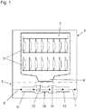
- a dishwasher 1 which is suitable for carrying out a method according to the application according to the application, shown in a schematic sectional view.
- the section is a vertical plane that runs perpendicular to a lying in the figures on the right front of the dishwasher 1.
- the dishwasher 1 has a washing compartment 2, can be admitted in the ware and is sprayed in the washing liquid for cleaning the dishes.
- a washing compartment 2 can be admitted in the ware and is sprayed in the washing liquid for cleaning the dishes.
- two items to be washed 3 are shown with items to be washed.
- For spraying the rinsing liquid for example rotating spray arms are present, which are not shown here for reasons of clarity.
- rinsing liquid collects in a collecting pot 4 in a lower portion of the washing compartment 2.
- the collecting pot 4 like the circulating pump, is arranged in a base 5 of the dishwasher 1 below the washing compartment 2.
- the washing compartment 2 of the dishwasher 1 is accessible from the front via a pivotable door, on which a (furniture) front is placed to give a kitchen unit in which the dishwasher 1 is installed, a uniform appearance.
- a pivotable door on which a (furniture) front is placed to give a kitchen unit in which the dishwasher 1 is installed, a uniform appearance.
- the pivoting door together with the (furniture) front in the figure is not shown in detail.
- the base 5 runs from front to back an air duct 10 in which a heat exchanger 13 of an evaporator and at least one fan 14 is located.
- the evaporator is part of a heat pump cycle, not shown further, is absorbed by the heat from the environment and is used to heat the rinsing liquid.
- an air inlet 11 is arranged, via which air can be sucked into the air duct 10.
- an air filter can be positioned, through which air is sucked into the air duct 5 via the fan 14 during operation of the dishwasher 1 when using the heat pump.
- FIGS. 2 to 6 various embodiments of air ducts 10 are shown in a heat pump cycle, for example, the in Fig. 1 Dishwasher 1 shown can be used and allow the implementation of an according to the application operating method.
- like reference numerals designate the same or equivalent elements.
- Fig. 2 shows in a schematic sectional view of a first example of an air duct 10, which in the dishwasher 1 of Fig. 1 can be used.
- the air duct 10 has an air inlet 11, into which inflowing air 6 enters, and an air outlet 12, from which outflowing air 7 exits.
- a heat exchanger 13 is positioned, which is traversed by the incoming air 6.
- a fan 14 designed here as an axial fan, is arranged in the air duct 10 in this example behind the heat exchanger 13.
- the fan 14 is coupled to a controller, not shown here, which can control it variable speed.
- the controller is integrated in a higher-level control device of the dishwasher 1.
- the fan 14 may for example be a DC motor with collector, which is driven in a PWM (Pulse Width Modulation) - method.
- PWM Pulse Width Modulation
- the fan 14 can be arranged behind the heat exchanger 13 in the air flow direction. It is also possible in alternative embodiments to arrange the fan 14 in front of the heat exchanger 13. Furthermore, it is also possible to use two or more ventilators 14 positioned in succession, which are positioned in front of, behind or partially before and partly behind the heat exchanger 13.
- a temperature sensor 16, 17 is arranged in each case. With the two temperature sensors 16, 17, a temperature T1, T2 of the incoming air 6 and the outflowing air 7 can be measured correspondingly. One of the measured temperatures T1, T2 determined temperature difference, which is achieved by the heat exchanger 13 and / or the measured temperature of the outflowing air 7 can be used in one embodiment of the method according to the application for controlling the fan 14. For this purpose, the temperature sensors 16, 17 are coupled to the aforementioned control of the fan 14. The temperature sensors 16, 17 are evaluated to determine the temperatures T1, T2. Depending on the measured temperatures T1, T2 (and possibly other variables), the speed of the fan 14 is varied.
- the air flow can be increased by the speed of the fan 14 is increased.
- Fig. 3 shows an alternative embodiment of the air duct 10 of Fig. 2 ,
- two smaller fans are used instead of one fan 14, two smaller fans (based on the diameter of the vanes and thus the radial installation dimension) are used. This results in an advantageous in many installation situations flat rectangular cross-sectional shape of the air duct 10th
- a variation of the air flow through the air duct 10 can be carried out in this embodiment in that one or both of the fans 14 'are operated speed-controlled.
- one of the fans 14 ' may be turned on or off to vary the airflow in at least two stages.
- a check valve e.g. be provided in the form of a flap or a slider to prevent backflow of air.
- a temperature measurement can, as in Fig. 4 shown, in front of and behind the heat exchanger 13 and a pressure measurement by means of pressure sensors 18, 19 done.
- a first pressure p1 before the heat exchanger 13 and a second pressure p2 behind the heat exchanger 13 is determined.
- p1-p2 the delivered air volume flow can be determined. It can then be provided, for example, to control the fans 14 'depending on the measured pressure difference in order to operate the heat exchanger 13 and thus the heat pump cycle in an advantageous operating parameter range.
- the pressure measurement shown can of course also be used when using only one fan 14.
- the pressure measurement and in particular the determined pressure difference allows a conclusion about a degree of contamination of the heat exchanger 13.
- a signal can be generated which indicates the user to a necessary or reasonably carried out maintenance.
- FIG. 5 An alternative arrangement of the pressure sensors 18, 19 is in Fig. 5 shown.
- the pressure sensor 18 does not measure the pressure in the air duct 10 before the heat exchanger 13, but an ambient pressure.
- a pressure difference p1-p2 measured in this way makes it possible not only to measure a degree of soiling of the heat exchanger 13, but also of an air filter, possibly upstream of the heat exchanger 13.
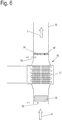
- An air duct 10 with an air filter 15 is exemplary in the Fig. 6 shown.
- the air filter 15 is upstream of the heat exchanger 13 to prevent contamination of the difficult to clean heat exchanger 13 by sucked dirt particles.
- a pressure difference p1-p2 allows conclusions about the degree of contamination of the air filter 15. If the determined degree of contamination exceeds a predetermined value, a signal can be output to the user requesting the change of the air filter 15.
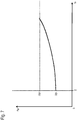
- FIG. 7 The diagram shows a measured pressure difference ⁇ p as a function of an operating time t B on a vertical axis.
- the pressure difference ⁇ p is performed in this operating method for a fixed predetermined speed of the fans 14 '. This can be done, for example, in a short measuring cycle at the beginning of each dishwashing cycle of a dishwasher.
- the course of the measured pressure difference Ap in the course of the operating time t B of the dishwasher is shown in a curve 20. It can be seen that the pressure difference ⁇ p increases as the operating time t B increases, with this increase becoming steeper and steeper over the course of the operating time.
- a predetermined pressure difference limit value ⁇ p G is plotted as a horizontal line in the diagram. The rise of the curve 20 indicates an increase in the clogging of the air filter 15. As soon as the pressure difference ⁇ p reaches the pressure difference limit value Ap G , the said signal is output to the user requesting to change the air filter 15.
- the in the Fig. 4-6 illustrated pressure measurement and in particular the determination of a differential pressure also makes it possible to carry out the operation of the heat pump cycle in the dishwasher more efficient.
- the air volume flow can be determined from a measurement of the differential pressure.
- the plant characteristic can be stored in a control unit of the dishwasher. It can then be adjusted by speed variation of the fans 14, 14 'of the air flow in the direction of an optimum for the process air flow.
- the room and / or ambient temperature can be used to determine the optimum air volume flow.
- independent temperature sensors 16, 17 are determined or by a temperature sensor, which is already present in the dishwasher and determines, for example, the temperature of the rinsing liquid.
- a value of such a temperature sensor, measured at the beginning of the rinsing process, reflects the room / ambient temperature. Possibly.
- a temperature value can also be queried by the control device of the dishwasher via a building control system.
- a power of a compressor in the heat pump cycle can also be controlled if a speed-controllable compressor is used.
- the mentioned control possibilities of the process can be combined, and also be selected depending on a washing program carried out by the dishwasher.
- the process control can, for example be designed differently, depending on whether a particularly energy-efficient wash program or a particularly fast or very quiet wash program should be performed.
- the time dependence is this time (unlike the diagram of the Fig. 7 ) in the course of a wash program, wherein the time ts indicate the program start and the time t E the end of the program.
- the change of the pressure difference ⁇ p from an initial value ⁇ p 0 runs according to the illustrated curve 21 for a constant speed of the fans 14, 14 '.
- One reason for the increase in the pressure difference .DELTA.p is an increasing condensation of the heat exchanger 13, which is symbolized by the dewing curve 24 rising during the program.
- a differential pressure limit ⁇ p G is defined, which is exceeded by the curve 21 approximately in the middle of the program runtime.
- a speed of the fans 14, 14 ' is to be increased after exceeding the pressure difference limit value ⁇ p G.
Landscapes
- Washing And Drying Of Tableware (AREA)
Applications Claiming Priority (3)
| Application Number | Priority Date | Filing Date | Title |
|---|---|---|---|
| DE102017115585.6A DE102017115585B4 (de) | 2017-07-12 | 2017-07-12 | Geschirrspülmaschine und Verfahren zum Betreiben einer Geschirrspülmaschine |
| DE102018101370 | 2018-01-23 | ||
| DE102018101373 | 2018-01-23 |
Publications (2)
| Publication Number | Publication Date |
|---|---|
| EP3427632A1 true EP3427632A1 (fr) | 2019-01-16 |
| EP3427632B1 EP3427632B1 (fr) | 2022-11-02 |
Family
ID=62874593
Family Applications (1)
| Application Number | Title | Priority Date | Filing Date |
|---|---|---|---|
| EP18181796.6A Active EP3427632B1 (fr) | 2017-07-12 | 2018-07-05 | Procédé de fonctionnement pour un lave-vaisselle doté d'un circuit de pompe à chaleur et lave-vaisselle doté d'un circuit de pompe à chaleur |
Country Status (1)
| Country | Link |
|---|---|
| EP (1) | EP3427632B1 (fr) |
Cited By (1)
| Publication number | Priority date | Publication date | Assignee | Title |
|---|---|---|---|---|
| WO2025098933A1 (fr) * | 2023-11-06 | 2025-05-15 | Winterhalter Product & Technology GmbH | Lave-vaisselle comprenant un dispositif de pompe à chaleur et un dispositif d'aspiration d'air de machine et d'air ambiant |
Citations (7)
| Publication number | Priority date | Publication date | Assignee | Title |
|---|---|---|---|---|
| DE4330456C1 (de) * | 1993-09-08 | 1995-03-16 | Blomberg Werke Gmbh | Wäschetrockner |
| WO2007049190A1 (fr) * | 2005-10-25 | 2007-05-03 | Arcelik Anonim Sirketi | Seche-linge |
| WO2013050262A1 (fr) * | 2011-10-04 | 2013-04-11 | Arcelik Anonim Sirketi | Sèche-linge avec pompe à chaleur |
| EP2647755A1 (fr) * | 2013-03-13 | 2013-10-09 | V-Zug AG | Dispositif de traitement de linge doté d'un filtre commutable |
| EP2682038A2 (fr) | 2012-07-03 | 2014-01-08 | Miele & Cie. KG | Lave-vaisselle et procédé de fonctionnement d'un lave-vaisselle |
| WO2015074834A1 (fr) * | 2013-11-22 | 2015-05-28 | Arcelik Anonim Sirketi | Lave-vaisselle comprenant une pompe à chaleur |
| WO2015185086A1 (fr) | 2014-06-02 | 2015-12-10 | Electrolux Appliances Aktiebolag | Appareil électroménager |
-
2018
- 2018-07-05 EP EP18181796.6A patent/EP3427632B1/fr active Active
Patent Citations (7)
| Publication number | Priority date | Publication date | Assignee | Title |
|---|---|---|---|---|
| DE4330456C1 (de) * | 1993-09-08 | 1995-03-16 | Blomberg Werke Gmbh | Wäschetrockner |
| WO2007049190A1 (fr) * | 2005-10-25 | 2007-05-03 | Arcelik Anonim Sirketi | Seche-linge |
| WO2013050262A1 (fr) * | 2011-10-04 | 2013-04-11 | Arcelik Anonim Sirketi | Sèche-linge avec pompe à chaleur |
| EP2682038A2 (fr) | 2012-07-03 | 2014-01-08 | Miele & Cie. KG | Lave-vaisselle et procédé de fonctionnement d'un lave-vaisselle |
| EP2647755A1 (fr) * | 2013-03-13 | 2013-10-09 | V-Zug AG | Dispositif de traitement de linge doté d'un filtre commutable |
| WO2015074834A1 (fr) * | 2013-11-22 | 2015-05-28 | Arcelik Anonim Sirketi | Lave-vaisselle comprenant une pompe à chaleur |
| WO2015185086A1 (fr) | 2014-06-02 | 2015-12-10 | Electrolux Appliances Aktiebolag | Appareil électroménager |
Cited By (1)
| Publication number | Priority date | Publication date | Assignee | Title |
|---|---|---|---|---|
| WO2025098933A1 (fr) * | 2023-11-06 | 2025-05-15 | Winterhalter Product & Technology GmbH | Lave-vaisselle comprenant un dispositif de pompe à chaleur et un dispositif d'aspiration d'air de machine et d'air ambiant |
Also Published As
| Publication number | Publication date |
|---|---|
| EP3427632B1 (fr) | 2022-11-02 |
Similar Documents
| Publication | Publication Date | Title |
|---|---|---|
| EP2775215B1 (fr) | Four de cuisson comprenant une limitation de température dépendant de l'atmosphère dans le four | |
| DE102007017284B3 (de) | Temperaturerfassung bei Zeolithtrocknung | |
| DE3030066C2 (de) | Drehzahlregeleinrichtung für einen Gebläsemotor eines Staubsaugers | |
| DE102012105902A1 (de) | Geschirrspülmaschine und Verfahren zum Betreiben einer Geschirrspülmaschine | |
| EP3214990B1 (fr) | Lave-vaisselle pourvu d'un système de sechage | |
| DE102013213546B4 (de) | Verfahren zum Betreiben eines Dunstabzugs und Dunstabzug | |
| EP2371258A2 (fr) | Lave-vaisselle doté d'une aération de seuil de porte | |
| DE212020000314U1 (de) | Intelligentes Mückenschutzsystem für eine Klimaanlage | |
| DE102018004587B3 (de) | Sicherheitswerkbank mit geregeltem Umluftstrom sowie Verfahren zu deren Betrieb | |
| WO2005070275A1 (fr) | Appareil electromenager a circulation de liquide | |
| EP1906096A2 (fr) | Procédé destiné au réglage du débit d'air d'un compartiment d'un four | |
| EP3437477B1 (fr) | Appareil de cuisson et méthode d'utilisation d'un appareil de cuisson | |
| EP2508810B1 (fr) | Module de ventilateur | |
| EP3431891A1 (fr) | Humidificateur et procédé de conditionnement d'air | |
| DE202017007441U1 (de) | Staubsauger | |
| EP2765359B1 (fr) | Procédé de surveillance d'un flux d'air dans une gaine d'aération | |
| DE19728578C2 (de) | Verfahren zur außentaupunktabhängigen Verdampfertemperatursteuerung | |
| EP1554526A1 (fr) | Systeme d'echange d'air destine a la ventilation au moins d'une piece d'un batiment | |
| EP3427632B1 (fr) | Procédé de fonctionnement pour un lave-vaisselle doté d'un circuit de pompe à chaleur et lave-vaisselle doté d'un circuit de pompe à chaleur | |
| DE102005024631A1 (de) | Dunstabzugsvorrichtung | |
| DE102017115585B4 (de) | Geschirrspülmaschine und Verfahren zum Betreiben einer Geschirrspülmaschine | |
| DE102019100010A1 (de) | Betriebsverfahren für eine Geschirrspülmaschine mit einem Wärmepumpenkreislauf und Geschirrspülmaschine mit einem Wärmepumpenkreislauf | |
| EP2474787B2 (fr) | Appareil de cuisson à vapeur | |
| EP3427631A1 (fr) | Lave-vaisselle à circuit de pompe à chaleur | |
| DE102008042757A1 (de) | Wäschetrockner und Verfahren zum Betreiben desselben |
Legal Events
| Date | Code | Title | Description |
|---|---|---|---|
| PUAI | Public reference made under article 153(3) epc to a published international application that has entered the european phase |
Free format text: ORIGINAL CODE: 0009012 |
|
| STAA | Information on the status of an ep patent application or granted ep patent |
Free format text: STATUS: THE APPLICATION HAS BEEN PUBLISHED |
|
| AK | Designated contracting states |
Kind code of ref document: A1 Designated state(s): AL AT BE BG CH CY CZ DE DK EE ES FI FR GB GR HR HU IE IS IT LI LT LU LV MC MK MT NL NO PL PT RO RS SE SI SK SM TR |
|
| AX | Request for extension of the european patent |
Extension state: BA ME |
|
| STAA | Information on the status of an ep patent application or granted ep patent |
Free format text: STATUS: REQUEST FOR EXAMINATION WAS MADE |
|
| 17P | Request for examination filed |
Effective date: 20190716 |
|
| RBV | Designated contracting states (corrected) |
Designated state(s): AL AT BE BG CH CY CZ DE DK EE ES FI FR GB GR HR HU IE IS IT LI LT LU LV MC MK MT NL NO PL PT RO RS SE SI SK SM TR |
|
| STAA | Information on the status of an ep patent application or granted ep patent |
Free format text: STATUS: EXAMINATION IS IN PROGRESS |
|
| 17Q | First examination report despatched |
Effective date: 20200810 |
|
| GRAP | Despatch of communication of intention to grant a patent |
Free format text: ORIGINAL CODE: EPIDOSNIGR1 |
|
| STAA | Information on the status of an ep patent application or granted ep patent |
Free format text: STATUS: GRANT OF PATENT IS INTENDED |
|
| INTG | Intention to grant announced |
Effective date: 20220301 |
|
| GRAJ | Information related to disapproval of communication of intention to grant by the applicant or resumption of examination proceedings by the epo deleted |
Free format text: ORIGINAL CODE: EPIDOSDIGR1 |
|
| STAA | Information on the status of an ep patent application or granted ep patent |
Free format text: STATUS: EXAMINATION IS IN PROGRESS |
|
| INTC | Intention to grant announced (deleted) | ||
| GRAP | Despatch of communication of intention to grant a patent |
Free format text: ORIGINAL CODE: EPIDOSNIGR1 |
|
| STAA | Information on the status of an ep patent application or granted ep patent |
Free format text: STATUS: GRANT OF PATENT IS INTENDED |
|
| INTG | Intention to grant announced |
Effective date: 20220623 |
|
| GRAS | Grant fee paid |
Free format text: ORIGINAL CODE: EPIDOSNIGR3 |
|
| GRAA | (expected) grant |
Free format text: ORIGINAL CODE: 0009210 |
|
| STAA | Information on the status of an ep patent application or granted ep patent |
Free format text: STATUS: THE PATENT HAS BEEN GRANTED |
|
| REG | Reference to a national code |
Ref country code: DE Ref legal event code: R084 Ref document number: 502018010948 Country of ref document: DE |
|
| AK | Designated contracting states |
Kind code of ref document: B1 Designated state(s): AL AT BE BG CH CY CZ DE DK EE ES FI FR GB GR HR HU IE IS IT LI LT LU LV MC MK MT NL NO PL PT RO RS SE SI SK SM TR |
|
| REG | Reference to a national code |
Ref country code: GB Ref legal event code: FG4D Free format text: NOT ENGLISH |
|
| REG | Reference to a national code |
Ref country code: CH Ref legal event code: EP Ref country code: AT Ref legal event code: REF Ref document number: 1528145 Country of ref document: AT Kind code of ref document: T Effective date: 20221115 |
|
| REG | Reference to a national code |
Ref country code: DE Ref legal event code: R096 Ref document number: 502018010948 Country of ref document: DE |
|
| REG | Reference to a national code |
Ref country code: IE Ref legal event code: FG4D Free format text: LANGUAGE OF EP DOCUMENT: GERMAN |
|
| REG | Reference to a national code |
Ref country code: GB Ref legal event code: 746 Effective date: 20221129 |
|
| REG | Reference to a national code |
Ref country code: LT Ref legal event code: MG9D |
|
| REG | Reference to a national code |
Ref country code: NL Ref legal event code: MP Effective date: 20221102 |
|
| PG25 | Lapsed in a contracting state [announced via postgrant information from national office to epo] |
Ref country code: SE Free format text: LAPSE BECAUSE OF FAILURE TO SUBMIT A TRANSLATION OF THE DESCRIPTION OR TO PAY THE FEE WITHIN THE PRESCRIBED TIME-LIMIT Effective date: 20221102 Ref country code: PT Free format text: LAPSE BECAUSE OF FAILURE TO SUBMIT A TRANSLATION OF THE DESCRIPTION OR TO PAY THE FEE WITHIN THE PRESCRIBED TIME-LIMIT Effective date: 20230302 Ref country code: NO Free format text: LAPSE BECAUSE OF FAILURE TO SUBMIT A TRANSLATION OF THE DESCRIPTION OR TO PAY THE FEE WITHIN THE PRESCRIBED TIME-LIMIT Effective date: 20230202 Ref country code: LT Free format text: LAPSE BECAUSE OF FAILURE TO SUBMIT A TRANSLATION OF THE DESCRIPTION OR TO PAY THE FEE WITHIN THE PRESCRIBED TIME-LIMIT Effective date: 20221102 Ref country code: FI Free format text: LAPSE BECAUSE OF FAILURE TO SUBMIT A TRANSLATION OF THE DESCRIPTION OR TO PAY THE FEE WITHIN THE PRESCRIBED TIME-LIMIT Effective date: 20221102 Ref country code: ES Free format text: LAPSE BECAUSE OF FAILURE TO SUBMIT A TRANSLATION OF THE DESCRIPTION OR TO PAY THE FEE WITHIN THE PRESCRIBED TIME-LIMIT Effective date: 20221102 |
|
| PG25 | Lapsed in a contracting state [announced via postgrant information from national office to epo] |
Ref country code: RS Free format text: LAPSE BECAUSE OF FAILURE TO SUBMIT A TRANSLATION OF THE DESCRIPTION OR TO PAY THE FEE WITHIN THE PRESCRIBED TIME-LIMIT Effective date: 20221102 Ref country code: PL Free format text: LAPSE BECAUSE OF FAILURE TO SUBMIT A TRANSLATION OF THE DESCRIPTION OR TO PAY THE FEE WITHIN THE PRESCRIBED TIME-LIMIT Effective date: 20221102 Ref country code: LV Free format text: LAPSE BECAUSE OF FAILURE TO SUBMIT A TRANSLATION OF THE DESCRIPTION OR TO PAY THE FEE WITHIN THE PRESCRIBED TIME-LIMIT Effective date: 20221102 Ref country code: IS Free format text: LAPSE BECAUSE OF FAILURE TO SUBMIT A TRANSLATION OF THE DESCRIPTION OR TO PAY THE FEE WITHIN THE PRESCRIBED TIME-LIMIT Effective date: 20230302 Ref country code: HR Free format text: LAPSE BECAUSE OF FAILURE TO SUBMIT A TRANSLATION OF THE DESCRIPTION OR TO PAY THE FEE WITHIN THE PRESCRIBED TIME-LIMIT Effective date: 20221102 Ref country code: GR Free format text: LAPSE BECAUSE OF FAILURE TO SUBMIT A TRANSLATION OF THE DESCRIPTION OR TO PAY THE FEE WITHIN THE PRESCRIBED TIME-LIMIT Effective date: 20230203 |
|
| PG25 | Lapsed in a contracting state [announced via postgrant information from national office to epo] |
Ref country code: NL Free format text: LAPSE BECAUSE OF FAILURE TO SUBMIT A TRANSLATION OF THE DESCRIPTION OR TO PAY THE FEE WITHIN THE PRESCRIBED TIME-LIMIT Effective date: 20221102 |
|
| P01 | Opt-out of the competence of the unified patent court (upc) registered |
Effective date: 20230528 |
|
| PG25 | Lapsed in a contracting state [announced via postgrant information from national office to epo] |
Ref country code: SM Free format text: LAPSE BECAUSE OF FAILURE TO SUBMIT A TRANSLATION OF THE DESCRIPTION OR TO PAY THE FEE WITHIN THE PRESCRIBED TIME-LIMIT Effective date: 20221102 Ref country code: RO Free format text: LAPSE BECAUSE OF FAILURE TO SUBMIT A TRANSLATION OF THE DESCRIPTION OR TO PAY THE FEE WITHIN THE PRESCRIBED TIME-LIMIT Effective date: 20221102 Ref country code: EE Free format text: LAPSE BECAUSE OF FAILURE TO SUBMIT A TRANSLATION OF THE DESCRIPTION OR TO PAY THE FEE WITHIN THE PRESCRIBED TIME-LIMIT Effective date: 20221102 Ref country code: DK Free format text: LAPSE BECAUSE OF FAILURE TO SUBMIT A TRANSLATION OF THE DESCRIPTION OR TO PAY THE FEE WITHIN THE PRESCRIBED TIME-LIMIT Effective date: 20221102 Ref country code: CZ Free format text: LAPSE BECAUSE OF FAILURE TO SUBMIT A TRANSLATION OF THE DESCRIPTION OR TO PAY THE FEE WITHIN THE PRESCRIBED TIME-LIMIT Effective date: 20221102 |
|
| REG | Reference to a national code |
Ref country code: DE Ref legal event code: R097 Ref document number: 502018010948 Country of ref document: DE |
|
| PG25 | Lapsed in a contracting state [announced via postgrant information from national office to epo] |
Ref country code: SK Free format text: LAPSE BECAUSE OF FAILURE TO SUBMIT A TRANSLATION OF THE DESCRIPTION OR TO PAY THE FEE WITHIN THE PRESCRIBED TIME-LIMIT Effective date: 20221102 Ref country code: AL Free format text: LAPSE BECAUSE OF FAILURE TO SUBMIT A TRANSLATION OF THE DESCRIPTION OR TO PAY THE FEE WITHIN THE PRESCRIBED TIME-LIMIT Effective date: 20221102 |
|
| PLBE | No opposition filed within time limit |
Free format text: ORIGINAL CODE: 0009261 |
|
| STAA | Information on the status of an ep patent application or granted ep patent |
Free format text: STATUS: NO OPPOSITION FILED WITHIN TIME LIMIT |
|
| 26N | No opposition filed |
Effective date: 20230803 |
|
| PG25 | Lapsed in a contracting state [announced via postgrant information from national office to epo] |
Ref country code: SI Free format text: LAPSE BECAUSE OF FAILURE TO SUBMIT A TRANSLATION OF THE DESCRIPTION OR TO PAY THE FEE WITHIN THE PRESCRIBED TIME-LIMIT Effective date: 20221102 |
|
| PG25 | Lapsed in a contracting state [announced via postgrant information from national office to epo] |
Ref country code: MC Free format text: LAPSE BECAUSE OF FAILURE TO SUBMIT A TRANSLATION OF THE DESCRIPTION OR TO PAY THE FEE WITHIN THE PRESCRIBED TIME-LIMIT Effective date: 20221102 |
|
| PG25 | Lapsed in a contracting state [announced via postgrant information from national office to epo] |
Ref country code: MC Free format text: LAPSE BECAUSE OF FAILURE TO SUBMIT A TRANSLATION OF THE DESCRIPTION OR TO PAY THE FEE WITHIN THE PRESCRIBED TIME-LIMIT Effective date: 20221102 |
|
| REG | Reference to a national code |
Ref country code: CH Ref legal event code: PL |
|
| REG | Reference to a national code |
Ref country code: BE Ref legal event code: MM Effective date: 20230731 |
|
| PG25 | Lapsed in a contracting state [announced via postgrant information from national office to epo] |
Ref country code: LU Free format text: LAPSE BECAUSE OF NON-PAYMENT OF DUE FEES Effective date: 20230705 |
|
| PG25 | Lapsed in a contracting state [announced via postgrant information from national office to epo] |
Ref country code: LU Free format text: LAPSE BECAUSE OF NON-PAYMENT OF DUE FEES Effective date: 20230705 |
|
| REG | Reference to a national code |
Ref country code: IE Ref legal event code: MM4A |
|
| PG25 | Lapsed in a contracting state [announced via postgrant information from national office to epo] |
Ref country code: CH Free format text: LAPSE BECAUSE OF NON-PAYMENT OF DUE FEES Effective date: 20230731 |
|
| PG25 | Lapsed in a contracting state [announced via postgrant information from national office to epo] |
Ref country code: BE Free format text: LAPSE BECAUSE OF NON-PAYMENT OF DUE FEES Effective date: 20230731 |
|
| PG25 | Lapsed in a contracting state [announced via postgrant information from national office to epo] |
Ref country code: IE Free format text: LAPSE BECAUSE OF NON-PAYMENT OF DUE FEES Effective date: 20230705 |
|
| PG25 | Lapsed in a contracting state [announced via postgrant information from national office to epo] |
Ref country code: IE Free format text: LAPSE BECAUSE OF NON-PAYMENT OF DUE FEES Effective date: 20230705 |
|
| REG | Reference to a national code |
Ref country code: AT Ref legal event code: MM01 Ref document number: 1528145 Country of ref document: AT Kind code of ref document: T Effective date: 20230705 |
|
| PG25 | Lapsed in a contracting state [announced via postgrant information from national office to epo] |
Ref country code: AT Free format text: LAPSE BECAUSE OF NON-PAYMENT OF DUE FEES Effective date: 20230705 |
|
| PG25 | Lapsed in a contracting state [announced via postgrant information from national office to epo] |
Ref country code: AT Free format text: LAPSE BECAUSE OF NON-PAYMENT OF DUE FEES Effective date: 20230705 |
|
| PG25 | Lapsed in a contracting state [announced via postgrant information from national office to epo] |
Ref country code: BG Free format text: LAPSE BECAUSE OF FAILURE TO SUBMIT A TRANSLATION OF THE DESCRIPTION OR TO PAY THE FEE WITHIN THE PRESCRIBED TIME-LIMIT Effective date: 20221102 |
|
| PG25 | Lapsed in a contracting state [announced via postgrant information from national office to epo] |
Ref country code: BG Free format text: LAPSE BECAUSE OF FAILURE TO SUBMIT A TRANSLATION OF THE DESCRIPTION OR TO PAY THE FEE WITHIN THE PRESCRIBED TIME-LIMIT Effective date: 20221102 |
|
| PG25 | Lapsed in a contracting state [announced via postgrant information from national office to epo] |
Ref country code: CY Free format text: LAPSE BECAUSE OF FAILURE TO SUBMIT A TRANSLATION OF THE DESCRIPTION OR TO PAY THE FEE WITHIN THE PRESCRIBED TIME-LIMIT; INVALID AB INITIO Effective date: 20180705 |
|
| PGFP | Annual fee paid to national office [announced via postgrant information from national office to epo] |
Ref country code: TR Payment date: 20250624 Year of fee payment: 8 |
|
| PG25 | Lapsed in a contracting state [announced via postgrant information from national office to epo] |
Ref country code: HU Free format text: LAPSE BECAUSE OF FAILURE TO SUBMIT A TRANSLATION OF THE DESCRIPTION OR TO PAY THE FEE WITHIN THE PRESCRIBED TIME-LIMIT; INVALID AB INITIO Effective date: 20180705 |
|
| PGFP | Annual fee paid to national office [announced via postgrant information from national office to epo] |
Ref country code: DE Payment date: 20250731 Year of fee payment: 8 |
|
| PGFP | Annual fee paid to national office [announced via postgrant information from national office to epo] |
Ref country code: IT Payment date: 20250721 Year of fee payment: 8 |
|
| PGFP | Annual fee paid to national office [announced via postgrant information from national office to epo] |
Ref country code: GB Payment date: 20250722 Year of fee payment: 8 |
|
| PGFP | Annual fee paid to national office [announced via postgrant information from national office to epo] |
Ref country code: FR Payment date: 20250725 Year of fee payment: 8 |