EP2682038A2 - Lave-vaisselle et procédé de fonctionnement d'un lave-vaisselle - Google Patents
Lave-vaisselle et procédé de fonctionnement d'un lave-vaisselle Download PDFInfo
- Publication number
- EP2682038A2 EP2682038A2 EP13401064.4A EP13401064A EP2682038A2 EP 2682038 A2 EP2682038 A2 EP 2682038A2 EP 13401064 A EP13401064 A EP 13401064A EP 2682038 A2 EP2682038 A2 EP 2682038A2
- Authority
- EP
- European Patent Office
- Prior art keywords
- dishwasher
- air
- flow
- evaporator
- supply air
- Prior art date
- Legal status (The legal status is an assumption and is not a legal conclusion. Google has not performed a legal analysis and makes no representation as to the accuracy of the status listed.)
- Withdrawn
Links
Images


Classifications
-
- A—HUMAN NECESSITIES
- A47—FURNITURE; DOMESTIC ARTICLES OR APPLIANCES; COFFEE MILLS; SPICE MILLS; SUCTION CLEANERS IN GENERAL
- A47L—DOMESTIC WASHING OR CLEANING; SUCTION CLEANERS IN GENERAL
- A47L15/00—Washing or rinsing machines for crockery or tableware
- A47L15/0018—Controlling processes, i.e. processes to control the operation of the machine characterised by the purpose or target of the control
- A47L15/0052—Noise reduction
-
- A—HUMAN NECESSITIES
- A47—FURNITURE; DOMESTIC ARTICLES OR APPLIANCES; COFFEE MILLS; SPICE MILLS; SUCTION CLEANERS IN GENERAL
- A47L—DOMESTIC WASHING OR CLEANING; SUCTION CLEANERS IN GENERAL
- A47L15/00—Washing or rinsing machines for crockery or tableware
- A47L15/42—Details
- A47L15/4285—Water-heater arrangements
-
- A—HUMAN NECESSITIES
- A47—FURNITURE; DOMESTIC ARTICLES OR APPLIANCES; COFFEE MILLS; SPICE MILLS; SUCTION CLEANERS IN GENERAL
- A47L—DOMESTIC WASHING OR CLEANING; SUCTION CLEANERS IN GENERAL
- A47L15/00—Washing or rinsing machines for crockery or tableware
- A47L15/42—Details
- A47L15/48—Drying arrangements
- A47L15/486—Blower arrangements
-
- A—HUMAN NECESSITIES
- A47—FURNITURE; DOMESTIC ARTICLES OR APPLIANCES; COFFEE MILLS; SPICE MILLS; SUCTION CLEANERS IN GENERAL
- A47L—DOMESTIC WASHING OR CLEANING; SUCTION CLEANERS IN GENERAL
- A47L15/00—Washing or rinsing machines for crockery or tableware
- A47L15/42—Details
- A47L15/48—Drying arrangements
- A47L15/488—Connections of the tub with the ambient air, e.g. air intake or venting arrangements
-
- A—HUMAN NECESSITIES
- A47—FURNITURE; DOMESTIC ARTICLES OR APPLIANCES; COFFEE MILLS; SPICE MILLS; SUCTION CLEANERS IN GENERAL
- A47L—DOMESTIC WASHING OR CLEANING; SUCTION CLEANERS IN GENERAL
- A47L15/00—Washing or rinsing machines for crockery or tableware
- A47L15/0018—Controlling processes, i.e. processes to control the operation of the machine characterised by the purpose or target of the control
- A47L15/0047—Energy or water consumption, e.g. by saving energy or water
-
- A—HUMAN NECESSITIES
- A47—FURNITURE; DOMESTIC ARTICLES OR APPLIANCES; COFFEE MILLS; SPICE MILLS; SUCTION CLEANERS IN GENERAL
- A47L—DOMESTIC WASHING OR CLEANING; SUCTION CLEANERS IN GENERAL
- A47L15/00—Washing or rinsing machines for crockery or tableware
- A47L15/42—Details
- A47L15/4251—Details of the casing
- A47L15/4257—Details of the loading door
-
- A—HUMAN NECESSITIES
- A47—FURNITURE; DOMESTIC ARTICLES OR APPLIANCES; COFFEE MILLS; SPICE MILLS; SUCTION CLEANERS IN GENERAL
- A47L—DOMESTIC WASHING OR CLEANING; SUCTION CLEANERS IN GENERAL
- A47L15/00—Washing or rinsing machines for crockery or tableware
- A47L15/42—Details
- A47L15/48—Drying arrangements
- A47L15/483—Drying arrangements by using condensers
-
- Y—GENERAL TAGGING OF NEW TECHNOLOGICAL DEVELOPMENTS; GENERAL TAGGING OF CROSS-SECTIONAL TECHNOLOGIES SPANNING OVER SEVERAL SECTIONS OF THE IPC; TECHNICAL SUBJECTS COVERED BY FORMER USPC CROSS-REFERENCE ART COLLECTIONS [XRACs] AND DIGESTS
- Y02—TECHNOLOGIES OR APPLICATIONS FOR MITIGATION OR ADAPTATION AGAINST CLIMATE CHANGE
- Y02B—CLIMATE CHANGE MITIGATION TECHNOLOGIES RELATED TO BUILDINGS, e.g. HOUSING, HOUSE APPLIANCES OR RELATED END-USER APPLICATIONS
- Y02B30/00—Energy efficient heating, ventilation or air conditioning [HVAC]
- Y02B30/52—Heat recovery pumps, i.e. heat pump based systems or units able to transfer the thermal energy from one area of the premises or part of the facilities to a different one, improving the overall efficiency
Definitions
- the invention relates to a dishwasher with an outer housing, a loading door, a base area and with a heat pump cycle, which has a fan, an evaporator, a compressor, a condenser, a throttle point and a flow circuit.
- a dishwasher of the type described above is in the DE 102011000042.9 described. It has an outer housing which, among other things, surrounds a rinsing container, into the rinsing space of which items to be cleaned are introduced.
- the dishwasher has a loading door which closes the outer housing and in particular the washing container, and a base area which is arranged below the loading door.
- the base area essentially contains most of the technical components of the dishwasher, such as collecting pot, circulating pump, water separator, suds pump and so on.
- the base area is covered in the front view of the dishwasher with a base to create a visually appealing front, for example, for integration into an existing kitchen furniture line.
- the dishwasher is also equipped with a heat pump circuit to reduce energy consumption, especially during the heating phase of the machine, since the heating process causes the largest part of the energy consumption of the dishwasher.
- the heat pump cycle has, in particular, an evaporator, a compressor, a condenser, a throttle point and a flow circuit connecting these components.
- the DE 102011000042.9 describes in particular a method for heating the dishwasher, in particular for heating rinse liquor, with an air-water heat pump.
- the dishwasher sucks indoor air (supply air), which is passed through the evaporator of the heat pump and cooled.
- the extracted heat energy from the room air is transferred to a working medium (refrigerant) and then compressed by means of the compressor and thus brought to a higher temperature level.
- the hot refrigerant condenses on the condenser and heats up the wash liquor.
- the cold air (exhaust air) leaving the evaporator is removed from the dishwasher led out.
- the air volume flow required for heating the dishwasher is significantly higher than the volume of air flow conveyed by drying systems in conventional dishwashers. Since the heating process typically has a time share of more than 50% of the total wash program, this air volume flow over a large period of time is required.
- the air intakes and air outlets, air ducts and the fan known from prior art drying systems are not suitable for this magnitude of the air volume flow and / or cause an increased, disturbing noise level during operation of the dishwasher. This is particularly annoying for those users who operate the dishwasher in smaller living spaces, for example 1-room apartments, and are in the immediate vicinity of the dishwasher.
- the invention proposes a dishwasher and a method according to the independent claims.
- Advantageous developments are contained in the subclaims or the description.
- the dishwasher according to the invention comprises an air-water heat pump for heating rinse liquor with a heat pump cycle, which comprises a fan, an evaporator, a compressor, a condenser, a throttle point and a Krömungsniklauf.
- a heat pump cycle which comprises a fan, an evaporator, a compressor, a condenser, a throttle point and a Krömungsniklauf.
- supply air is conveyed, for example drawn in, by the fan during the heating phase. This is passed through the evaporator of the heat pump and thereby cooled.
- the extracted heat energy from the supply air is transferred to a refrigerant and then compressed by means of the compressor and thus brought to a higher temperature level.
- the hot refrigerant condenses on the condenser and heats up the wash liquor.
- the cold exhaust air leaving the evaporator is directed out of the dishwasher.
- the dishwasher such as a domestic dishwasher, has a closable with a loading door in a conventional manner washroom.
- a washing program the items to be washed in the washing compartment are first rinsed and then dried.
- Rinsing typically includes several water-bearing program sections, such as the program sections CLEAN and RINSE.
- the flushing chamber is closed by the loading door.
- the supply air supplied by the fan which is the heat source of the heat pump
- room air ie air from the installation space of the dishwasher about the kitchen, which has in particular a usual for such rooms ambient temperature, ie about 15 to 25 ° C.
- the supply air or room air is conveyed during the heating phase of a washing program in which the washing liquor is heated, in particular during a water-conveying program section. The supply of air is thus carried out in particular when the loading door is closed.
- the fan is designed to deliver supply air at a flow rate between 30 m 3 / h and 300 m 3 / h.
- the recoverable or subsidized Volume flow is designed to deliver supply air at a flow rate between 30 m 3 / h and 300 m 3 / h.
- the recoverable or subsidized Volume flow is designed to deliver supply air at a flow rate between 30 m 3 / h and 300 m 3 / h.
- the recoverable or subsidized Volume flow is designed to deliver supply air at a flow rate between 30 m 3 / h and 300 m 3 / h.
- the recoverable or subsidized Volume flow is designed to deliver supply air at a flow rate between 30 m 3 / h and 300 m 3 / h.
- the recoverable or subsidized Volume flow is designed to deliver supply air at a flow rate between 30 m 3 / h and 300 m 3 / h.
- the recoverable or subsidized Volume flow is designed to deliver supply air
- the fan is arranged in the flow direction of the supply air behind the evaporator.
- the fan sucks the supply air thus, whereby the flow of the supply air is generated or given their direction of flow, and passes them in this way through the evaporator.
- the fan causes a certain increased noise level during operation due to the high volume flow. Due to the preferred arrangement behind the evaporator, however, the noise source represented by the fan is comparatively far away from the wall of the outer housing. As a result, the noise is kept moderate.
- the invention further provides that the base area, in particular the base, has one or more air inlets for the supply air.
- the loading door may also have one or more air inlets.
- the corresponding air outlets are arranged according to an embodiment on the opposite side of the feed door of the outer housing. As a result, the outlet of the exhaust air flow can be far away from the user.
- the air outlets may also be arranged on one of the side walls of the outer housing adjacent to the loading door. Preferably, however, are outlets on at least two side walls of the outer housing. It is particularly preferred if, before the exhaust air flow exits the air outlets, the exhaust air flow is split into a plurality of partial air flows flowing in different, preferably orthogonal, directions. The distribution of the exhaust air flow thus takes place in the dishwasher, in particular in the base area. Air outlets are preferably arranged in particular on both side walls of the outer housing adjacent to the loading door, and the air outlet from the dishwasher thus takes place in at least two partial flows flowing in opposite directions.
- the inventive geometrical arrangement which provides the air inlets on the front of the dishwasher, ie in the base area, in the base or in the loading door, while on the other hand, the air outlets are arranged on the sides and / or the rear wall of the outer housing, arises in the front area of the Dishwasher despite the high volume flow according to the invention no tangible draft by flowing out of the outer housing cold exhaust air. A leaking concentrated air flow would be noticeable here as a draft. Therefore, it is advantageous to suck in the supply air at the front and to direct the exhaust air, which is much cooler than the supply air, laterally or in the back region of the dishwasher under the adjacent kitchen cabinet area. About leaks or specially provided air outlet grille in the base of the kitchen cabinets, so a diffuse outflow can be achieved.
- the room air (supply air) is sucked in the front area of the dishwasher either over or through a skirting board. For this purpose, it is either completely or partially passed over a free space or a Einschwenk Scheme the door.
- the air inlet and the air outlets are provided with a grid.
- the grid can be configured such that it simultaneously serves as a flow conditioning element and can advantageously influence the flow parameters, such as, for example, the flow direction and flow velocity.
- Grids in air inlets and outlets are louvred grids, grids or perforated metal sheets.
- the invention further proposes that the one or more air inlets have filters.
- a filter can for example be embedded in the base of the dishwasher or be introduced into the baseboard of the kitchen, so that the user can easily clean the filter or even replace. Interchangeability can be achieved for example by a clip element. Preferably, by removing the filter, in particular the evaporator is accessible for cleaning.
- one or the air inlet and in particular the filter is preceded by a calming area, in which a flow calming of the supply air flow takes place.
- a flow calming of the supply air flow takes place in the calming area.
- the calming area thus has the effect that such particles, which have already reached the base area, settle before reaching the filter.
- the calming area is formed, for example, by a free space in the base area, which is arranged downstream of a flow constriction caused by the loading door and / or the door trim and the base of the dishwasher.
- the calming section is formed by the loading door 3 or door trim 3a, the skirting board 8 and the free space 7.
- the invention provides that the heat pump cycle is designed so that supply air and exhaust air have a temperature difference between 5K and 15K, in particular between 8K and 10K. These temperature differences are suitable to operate the heat pump cycle effectively and thus to achieve the fastest possible heating of the dishwasher, but at the same time not make the temperature difference so great that the exhaust air discharged from the dishwasher for the user is clearly perceived as a cold air flow.
- an air volume flow of, for example, 100 m 3 / h which is cooled by a temperature difference of 10 K through an evaporator, about 330 watts of sensitive cooling power are needed. This is sufficient to heat a domestic dishwasher in a still acceptable period of time with a heat pump.
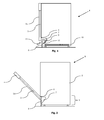
- FIG. 1 shows a dishwasher 1 with an outer housing 2, a loading door 3 and a control panel 4 and a base portion 5.
- the outer housing 2 encloses the washing compartment, not shown, heating, baskets, rinsing arms and so on.
- the base region 5 contains the components, not shown collecting pot, circulating pump, water separator, drain pump and other components known in the art.
- the illustrated dishwasher 1 is shown without the air circulation according to the invention.
- FIG. 2 is the side view of the dishwasher 1 according to FIG. 1 displayed.
- the loading door 3 which pivots about a pivot point 6 in a free space 7.
- the space 7 and a floor assembly, not shown, are covered by a base 8.
- FIG. 3 shows an embodiment of a dishwasher 1 according to the invention, which has an air intake 9 for supply air 11 (marked as white filled arrows) in the front region of the bottom assembly below the loading door 3.
- Black-filled arrows illustrate the exhaust air 12, which is discharged via the air outlets 10 on the sides of the dishwasher 1.
- the selected flow direction has the advantage that the supply air 11 is sucked in under the loading door 3 and thus no drafts occur in front of the dishwasher 1. A leaking concentrated air flow would be noticeable here as draft.
- the supply air 11 can be sucked in the front of the dishwasher 1 either above or through the base 8.
- the supply air 11 is led either completely or partially over the free space 7 and the Einschwenk Scheme the feed door 3.
- the air inlet 9 and the air outlets 10 are provided with a grid, not shown. This prevents the unwanted intrusion of foreign bodies or the reaching of a person into the air inlet 9 or into the air outlets 10.
- FIG. 5 shows the dishwasher 1 according to FIG. 4 in a top view.
- FIGS. 6 to 12 are other possible embodiments and arrangements of the air inlets 9 and air outlets 10.
- the air flow is, if not shown otherwise, as described above. However, reversing the air flow direction is conceivable and can bring advantages in certain installation situations.
- FIG. 6 shows two adjacent air inlets 9 and several, namely here without limiting the generality of three side by side laterally arranged air outlets 10th
- FIG. 7 an additional rear air outlet 10 in the base region 5 of the dishwasher 1 is shown.
- FIG. 5 illustrated shape with two side air outlets 10 could cause a disadvantage in some installation situations of the dishwasher 1. If one side of the dishwasher 1 is displaced by a deep base cabinet, for example a stove with a baking tray, this can cause an air volume reduction. With an additional air outlet 10, the amount of air and thus the efficient operation of the heat pump cycle 15 can be ensured.
- FIG. 8 shows a dishwasher 1, wherein the air inlet 9 is formed over approximately the entire height and width of the base 8.
- the air outlet 10 extends also over the entire depth of the outer housing 2 of the dishwasher 1.
- the air inlets 9 and air outlets 10 are arranged in the same level in the base 8.
- FIG. 10 shows a dishwasher 1 with an air inlet 9 in the base 8.
- the air outlets 10 are arranged on the side of the outer housing 2 adjacent to the loading door 3.
- the air flow of the exhaust air 12 thus exits via the joints between the dishwasher 1 and, for example, a built-in closet, not shown.
- FIG. 11 shows a dishwasher 1 with an air inlet 9 in the base 8. Air outlets 10 are arranged on the back of the dishwasher 1.
- FIG. 12 shows a variant of the dishwasher 1 according to FIG. 9 , According to FIG. 12
- an air inlet 9 is arranged in the base 8 of the dishwasher 1, while an air outlet 10 is arranged in the loading door 3.
- an air outlet 10 is arranged in the loading door 3.
- a reverse arrangement is conceivable, with the air inlet 9 in the loading door 3 and the air outlet 10 in the base 8.
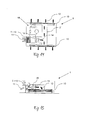
- FIG. 13 shows a schematic structure of a heat pump cycle 15 with the components evaporator 16, compressor 17, condenser 18, throttle 19 and flow circuit 20th
- a fan 14 sucks the ideally filtered supply air 11 through the evaporator 16.
- the supply air 11 is cooled in the evaporator 16.
- the cold air flow is led away via the fan 14 as exhaust air 12.
- air inlet 9, evaporator 16, fan 14 and air outlet 10 must be connected via an air passage 21.
- the arrangement of the fan 14 as seen in the flow direction behind the evaporator 16 has the advantage that by the suction of the supply air 11 at the outlet of the evaporator 16, the evaporator 16 is flowed through uniformly.
- the homogeneous flow in turn has the advantage that the heat pump circuit 15 can work with optimum efficiency, because all heat transfer surfaces are uniformly supplied with supply air 11.
- FIG. 14 shows the in FIG. 13 illustrated heat pump cycle 15, which is arranged in a dishwasher 1. Likewise, the airway 21 is shown in the region of the heat pump cycle 15.
- FIG. 15 shows the built-in a dishwasher 1 heat pump circuit 15 according to FIG. 14 in a side view.
- a not further shown filter element 13 is arranged at the air inlet 9 .
- the filter 13 is preferably designed so that it is easily removable and thus easy to clean. This is most easily achieved via the front of the dishwasher 1.
- the filter 13 is installed in the baseboard 8, which may be part of the kitchen skirting.
- the filter 13 would be easily removable.
- This arrangement has the advantage that the dishwasher 1 for removing and or cleaning the filter 13 does not have to be removed or moved.
- the filter cleaning should be possible without removal.
- the filter can be sucked off, for example with a vacuum cleaner.
- the filter 13 By removing the filter, the cleaning of the underlying evaporator 16 can also be made possible.
- a backwashing by the existing blower 14 is also proposed. Furthermore, it is advantageous if the filter 13 is arranged in a horizontal position and flows through from below.
- a calming region is connected upstream of the filter element 13.
- the air velocity is to be reduced in such a way that larger particles are not sucked in, thereby unduly reducing the filter performance.
- the calming area is formed by the loading door 3 or door trim 3a, the baseboard 8 and the free space 7.
Landscapes
- Washing And Drying Of Tableware (AREA)
- Structures Of Non-Positive Displacement Pumps (AREA)
Applications Claiming Priority (1)
| Application Number | Priority Date | Filing Date | Title |
|---|---|---|---|
| DE102012105902.0A DE102012105902A1 (de) | 2012-07-03 | 2012-07-03 | Geschirrspülmaschine und Verfahren zum Betreiben einer Geschirrspülmaschine |
Publications (2)
| Publication Number | Publication Date |
|---|---|
| EP2682038A2 true EP2682038A2 (fr) | 2014-01-08 |
| EP2682038A3 EP2682038A3 (fr) | 2014-03-05 |
Family
ID=48795539
Family Applications (1)
| Application Number | Title | Priority Date | Filing Date |
|---|---|---|---|
| EP13401064.4A Withdrawn EP2682038A3 (fr) | 2012-07-03 | 2013-07-02 | Lave-vaisselle et procédé de fonctionnement d'un lave-vaisselle |
Country Status (2)
| Country | Link |
|---|---|
| EP (1) | EP2682038A3 (fr) |
| DE (1) | DE102012105902A1 (fr) |
Cited By (27)
| Publication number | Priority date | Publication date | Assignee | Title |
|---|---|---|---|---|
| EP2921098A1 (fr) * | 2014-03-17 | 2015-09-23 | Samsung Electronics Co., Ltd. | Appareil domestique doté d'un appareil de séchage |
| DE102015222959B3 (de) * | 2015-11-20 | 2016-12-29 | BSH Hausgeräte GmbH | Geschirrspülmaschine mit einer Wärmepumpe |
| DE102015115036A1 (de) | 2015-09-08 | 2017-03-09 | Miele & Cie. Kg | Geschirrspülmaschine, insbesondere Haushaltsgeschirrspülmaschine |
| WO2018077635A1 (fr) * | 2016-10-26 | 2018-05-03 | BSH Hausgeräte GmbH | Lave-vaisselle à pompe thermique |
| EP3372139A1 (fr) | 2017-03-08 | 2018-09-12 | Miele & Cie. KG | Machine à nettoyer, en particulier lave-vaisselle électroménager |
| DE102017105385A1 (de) | 2017-03-14 | 2018-09-20 | Miele & Cie. Kg | Geschirrspülmaschine, insbesondere Haushaltsgeschirrspülmaschine |
| WO2018215331A1 (fr) | 2017-05-23 | 2018-11-29 | Miele & Cie. Kg | Lave-vaisselle, en particulier lave-vaisselle ménager |
| EP3409181A1 (fr) | 2017-05-29 | 2018-12-05 | Miele & Cie. KG | Machine à laver, en particulier lave-vaisselle domestique |
| EP3427632A1 (fr) | 2017-07-12 | 2019-01-16 | Miele & Cie. KG | Procédé de fonctionnement pour un lave-vaisselle doté d'un circuit de pompe à chaleur et lave-vaisselle doté d'un circuit de pompe à chaleur |
| EP3427628A1 (fr) | 2017-07-12 | 2019-01-16 | Miele & Cie. KG | Lave-vaisselle et son procédé de fonctionnement |
| EP3427631A1 (fr) | 2017-07-12 | 2019-01-16 | Miele & Cie. KG | Lave-vaisselle à circuit de pompe à chaleur |
| DE102017115585A1 (de) | 2017-07-12 | 2019-01-17 | Miele & Cie. Kg | Geschirrspülmaschine und Verfahren zum Betreiben einer Geschirrspülmaschine |
| WO2019034373A1 (fr) | 2017-08-18 | 2019-02-21 | Arcelik Anonim Sirketi | Lave-vaisselle comprenant une pompe à chaleur |
| DE102018127622A1 (de) | 2017-11-20 | 2019-05-23 | Miele & Cie. Kg | Geschirrspülmaschine mit Wärmepumpenkreislauf und Anordnung mit einer derartigen Geschirrspülmaschine und Unterbauzubehör |
| DE102018100013A1 (de) | 2018-01-02 | 2019-07-04 | Miele & Cie. Kg | Geschirrspülmaschine, insbesondere Haushaltsgeschirrspülmaschine |
| DE102018132411A1 (de) | 2018-01-02 | 2019-07-04 | Miele & Cie. Kg | Geschirrspülmaschine, insbesondere Haushaltsgeschirrspülmaschine |
| WO2019132819A2 (fr) | 2017-12-25 | 2019-07-04 | Arcelik Anonim Sirketi | Lave-vaisselle à pompe à chaleur |
| DE102019100004A1 (de) | 2018-01-16 | 2019-07-18 | Miele & Cie. Kg | Anordnung mit einer Geschirrspülmaschine |
| DE102019100002A1 (de) | 2018-01-16 | 2019-07-18 | Miele & Cie. Kg | Anordnung einer Geschirrspülmaschine mit Wärmepumpenkreislauf und Unterbauzubehör |
| DE102019100010A1 (de) | 2018-01-23 | 2019-07-25 | Miele & Cie. Kg | Betriebsverfahren für eine Geschirrspülmaschine mit einem Wärmepumpenkreislauf und Geschirrspülmaschine mit einem Wärmepumpenkreislauf |
| DE102018108654A1 (de) | 2018-04-12 | 2019-10-17 | Miele & Cie. Kg | Geschirrspülmaschine mit einem Wärmepumpenkreislauf und Betriebsverfahren für eine derartige Geschirrspülmaschine |
| WO2020001898A1 (fr) * | 2018-06-26 | 2020-01-02 | Arcelik Anonim Sirketi | Lave-vaisselle à pompe à chaleur |
| WO2022069646A1 (fr) * | 2020-09-30 | 2022-04-07 | BSH Hausgeräte GmbH | Lave-vaisselle présentant au moins une sortie d'air |
| EP4049579A1 (fr) | 2018-01-02 | 2022-08-31 | Miele & Cie. KG | Lave-vaisselle, en particulier lave-vaisselle électroménager |
| EP4066720A1 (fr) * | 2021-04-02 | 2022-10-05 | Arçelik Anonim Sirketi | Lave-vaisselle comprenant une pompe à chaleur |
| EP4133986A1 (fr) * | 2021-08-11 | 2023-02-15 | Whirlpool Corporation | Système de lave-vaisselle avec une barrière d'air pour condensation de porte |
| US12329345B2 (en) | 2020-09-30 | 2025-06-17 | BSH Hausgeräte GmbH | Household dishwasher having at least one air outlet |
Families Citing this family (2)
| Publication number | Priority date | Publication date | Assignee | Title |
|---|---|---|---|---|
| DE102018129627A1 (de) | 2018-11-23 | 2020-05-28 | Grohe Ag | Haushaltsgerät mit einer Geschirrspülmaschine und einer Wasseraufbereitungsanlage |
| DE102019108883A1 (de) * | 2019-04-04 | 2020-10-08 | Miele & Cie. Kg | Geschirrspülmaschine, insbesondere Haushaltsgeschirrspülmaschine |
Citations (5)
| Publication number | Priority date | Publication date | Assignee | Title |
|---|---|---|---|---|
| DE2643173A1 (de) * | 1975-08-29 | 1977-04-07 | Bonnet Ets | Geschirrwaschmaschine mit einer heiz- und temperaturregelanlage fuer ihr wasch- und spuelwasser |
| DE8915941U1 (de) * | 1989-01-17 | 1992-04-16 | AEG Hausgeräte GmbH, 90429 Nürnberg | Geschirrspülmaschine mit Entlüftungsöffnung |
| US5524358A (en) * | 1995-03-24 | 1996-06-11 | Matz; Warren W. | Dishwasher ventilation filtration kit |
| EP1825800A2 (fr) * | 2006-02-22 | 2007-08-29 | V-Zug AG | Lave-vaisselle ayant un moyen pour retirer l'humidité de la cuve |
| DE102011000042A1 (de) | 2011-01-05 | 2012-07-05 | Miele & Cie. Kg | Verfahren zum Durchführen eines Spülprogramms |
Family Cites Families (5)
| Publication number | Priority date | Publication date | Assignee | Title |
|---|---|---|---|---|
| CH502813A (de) * | 1969-08-27 | 1971-02-15 | Stierlen Werke Ag | Wärmerückgewinnungseinrichtung an einer Geschirrspülmaschine, insbesondere für gewerbliche Zwecke |
| DE2457182C2 (de) * | 1974-12-03 | 1983-09-15 | Stierlen-Maquet Ag, 7550 Rastatt | Wärmerückgewinnungseinrichtung für eine Geschirrspülmaschine |
| DE3048268A1 (de) * | 1980-12-20 | 1982-07-29 | Stierlen-Maquet Ag, 7550 Rastatt | Waermerueckgewinnungseinrichtung fuer geschirrspuelmaschinen |
| DE3214216A1 (de) * | 1980-12-20 | 1983-10-27 | Stierlen-Maquet Ag, 7550 Rastatt | Waermerueckgewinnungseinrichtung fuer geschirrspuelmaschinen |
| DE19707287C2 (de) * | 1997-02-24 | 2000-06-08 | Premark Feg L L C N D Ges D St | Wärmepumpe für eine Geschirrspülvorrichtung |
-
2012
- 2012-07-03 DE DE102012105902.0A patent/DE102012105902A1/de not_active Withdrawn
-
2013
- 2013-07-02 EP EP13401064.4A patent/EP2682038A3/fr not_active Withdrawn
Patent Citations (5)
| Publication number | Priority date | Publication date | Assignee | Title |
|---|---|---|---|---|
| DE2643173A1 (de) * | 1975-08-29 | 1977-04-07 | Bonnet Ets | Geschirrwaschmaschine mit einer heiz- und temperaturregelanlage fuer ihr wasch- und spuelwasser |
| DE8915941U1 (de) * | 1989-01-17 | 1992-04-16 | AEG Hausgeräte GmbH, 90429 Nürnberg | Geschirrspülmaschine mit Entlüftungsöffnung |
| US5524358A (en) * | 1995-03-24 | 1996-06-11 | Matz; Warren W. | Dishwasher ventilation filtration kit |
| EP1825800A2 (fr) * | 2006-02-22 | 2007-08-29 | V-Zug AG | Lave-vaisselle ayant un moyen pour retirer l'humidité de la cuve |
| DE102011000042A1 (de) | 2011-01-05 | 2012-07-05 | Miele & Cie. Kg | Verfahren zum Durchführen eines Spülprogramms |
Cited By (39)
| Publication number | Priority date | Publication date | Assignee | Title |
|---|---|---|---|---|
| EP2921098A1 (fr) * | 2014-03-17 | 2015-09-23 | Samsung Electronics Co., Ltd. | Appareil domestique doté d'un appareil de séchage |
| US10039434B2 (en) | 2014-03-17 | 2018-08-07 | Samsung Electronics Co., Ltd. | Household appliance having drying apparatus |
| DE102015115036A1 (de) | 2015-09-08 | 2017-03-09 | Miele & Cie. Kg | Geschirrspülmaschine, insbesondere Haushaltsgeschirrspülmaschine |
| EP3141176A1 (fr) | 2015-09-08 | 2017-03-15 | Miele & Cie. KG | Lave-vaisselle, notamment lave-vaisselle ménager |
| DE102015222959B3 (de) * | 2015-11-20 | 2016-12-29 | BSH Hausgeräte GmbH | Geschirrspülmaschine mit einer Wärmepumpe |
| WO2018077635A1 (fr) * | 2016-10-26 | 2018-05-03 | BSH Hausgeräte GmbH | Lave-vaisselle à pompe thermique |
| EP3372139A1 (fr) | 2017-03-08 | 2018-09-12 | Miele & Cie. KG | Machine à nettoyer, en particulier lave-vaisselle électroménager |
| DE102017105385A1 (de) | 2017-03-14 | 2018-09-20 | Miele & Cie. Kg | Geschirrspülmaschine, insbesondere Haushaltsgeschirrspülmaschine |
| WO2018215331A1 (fr) | 2017-05-23 | 2018-11-29 | Miele & Cie. Kg | Lave-vaisselle, en particulier lave-vaisselle ménager |
| EP3409181A1 (fr) | 2017-05-29 | 2018-12-05 | Miele & Cie. KG | Machine à laver, en particulier lave-vaisselle domestique |
| EP3409179A1 (fr) | 2017-05-29 | 2018-12-05 | Miele & Cie. KG | Machine à laver, en particulier lave-vaisselle domestique |
| EP3427632A1 (fr) | 2017-07-12 | 2019-01-16 | Miele & Cie. KG | Procédé de fonctionnement pour un lave-vaisselle doté d'un circuit de pompe à chaleur et lave-vaisselle doté d'un circuit de pompe à chaleur |
| EP3427628A1 (fr) | 2017-07-12 | 2019-01-16 | Miele & Cie. KG | Lave-vaisselle et son procédé de fonctionnement |
| EP3427631A1 (fr) | 2017-07-12 | 2019-01-16 | Miele & Cie. KG | Lave-vaisselle à circuit de pompe à chaleur |
| DE102017115585A1 (de) | 2017-07-12 | 2019-01-17 | Miele & Cie. Kg | Geschirrspülmaschine und Verfahren zum Betreiben einer Geschirrspülmaschine |
| DE102017115585B4 (de) * | 2017-07-12 | 2019-08-29 | Miele & Cie. Kg | Geschirrspülmaschine und Verfahren zum Betreiben einer Geschirrspülmaschine |
| WO2019034373A1 (fr) | 2017-08-18 | 2019-02-21 | Arcelik Anonim Sirketi | Lave-vaisselle comprenant une pompe à chaleur |
| DE102018127622A1 (de) | 2017-11-20 | 2019-05-23 | Miele & Cie. Kg | Geschirrspülmaschine mit Wärmepumpenkreislauf und Anordnung mit einer derartigen Geschirrspülmaschine und Unterbauzubehör |
| WO2019132819A2 (fr) | 2017-12-25 | 2019-07-04 | Arcelik Anonim Sirketi | Lave-vaisselle à pompe à chaleur |
| DE102018132411A1 (de) | 2018-01-02 | 2019-07-04 | Miele & Cie. Kg | Geschirrspülmaschine, insbesondere Haushaltsgeschirrspülmaschine |
| DE102018100013A1 (de) | 2018-01-02 | 2019-07-04 | Miele & Cie. Kg | Geschirrspülmaschine, insbesondere Haushaltsgeschirrspülmaschine |
| EP4049579A1 (fr) | 2018-01-02 | 2022-08-31 | Miele & Cie. KG | Lave-vaisselle, en particulier lave-vaisselle électroménager |
| DE102019100004A1 (de) | 2018-01-16 | 2019-07-18 | Miele & Cie. Kg | Anordnung mit einer Geschirrspülmaschine |
| DE102019100002A1 (de) | 2018-01-16 | 2019-07-18 | Miele & Cie. Kg | Anordnung einer Geschirrspülmaschine mit Wärmepumpenkreislauf und Unterbauzubehör |
| DE102019100010A1 (de) | 2018-01-23 | 2019-07-25 | Miele & Cie. Kg | Betriebsverfahren für eine Geschirrspülmaschine mit einem Wärmepumpenkreislauf und Geschirrspülmaschine mit einem Wärmepumpenkreislauf |
| DE102018108654A1 (de) | 2018-04-12 | 2019-10-17 | Miele & Cie. Kg | Geschirrspülmaschine mit einem Wärmepumpenkreislauf und Betriebsverfahren für eine derartige Geschirrspülmaschine |
| DE102018108654B4 (de) * | 2018-04-12 | 2025-09-04 | Miele & Cie. Kg | Geschirrspülmaschine mit einem Wärmepumpenkreislauf und Betriebsverfahren für eine derartige Geschirrspülmaschine |
| WO2020001898A1 (fr) * | 2018-06-26 | 2020-01-02 | Arcelik Anonim Sirketi | Lave-vaisselle à pompe à chaleur |
| US12329345B2 (en) | 2020-09-30 | 2025-06-17 | BSH Hausgeräte GmbH | Household dishwasher having at least one air outlet |
| CN116322459A (zh) * | 2020-09-30 | 2023-06-23 | Bsh家用电器有限公司 | 具有至少一个空气出口的家用洗碗机 |
| US12336680B2 (en) | 2020-09-30 | 2025-06-24 | BSH Hausgeräte GmbH | Dishwasher with at least one air outlet |
| WO2022069646A1 (fr) * | 2020-09-30 | 2022-04-07 | BSH Hausgeräte GmbH | Lave-vaisselle présentant au moins une sortie d'air |
| US12414669B2 (en) | 2020-09-30 | 2025-09-16 | BSH Hausgeräte GmbH | Household dishwasher having at least one air outlet |
| CN116322459B (zh) * | 2020-09-30 | 2025-10-17 | Bsh家用电器有限公司 | 具有至少一个空气出口的家用洗碗机 |
| US12458201B2 (en) | 2020-09-30 | 2025-11-04 | BSH Hausgeräte GmbH | Dishwasher with at least one air outlet |
| US12551088B2 (en) | 2020-09-30 | 2026-02-17 | BSH Hausgeräte GmbH | Household dishwasher having at least one air outlet |
| EP4066720A1 (fr) * | 2021-04-02 | 2022-10-05 | Arçelik Anonim Sirketi | Lave-vaisselle comprenant une pompe à chaleur |
| EP4133986A1 (fr) * | 2021-08-11 | 2023-02-15 | Whirlpool Corporation | Système de lave-vaisselle avec une barrière d'air pour condensation de porte |
| US20230046683A1 (en) * | 2021-08-11 | 2023-02-16 | Whirlpool Corporation | Air barrier for door condensation |
Also Published As
| Publication number | Publication date |
|---|---|
| DE102012105902A1 (de) | 2014-05-08 |
| EP2682038A3 (fr) | 2014-03-05 |
Similar Documents
| Publication | Publication Date | Title |
|---|---|---|
| EP2682038A2 (fr) | Lave-vaisselle et procédé de fonctionnement d'un lave-vaisselle | |
| EP2322072B1 (fr) | Lave-vaisselle doté d'un accumulateur thermique latent | |
| EP3214990B1 (fr) | Lave-vaisselle pourvu d'un système de sechage | |
| EP2682039B1 (fr) | Lave-vaisselle doté d'une pompe à chaleur | |
| DE102010061343A1 (de) | Verfahren und Vorrichtung für Geschirrspüler mit von mehreren Behandlungskammern gemeinsam genutztem Heizelement | |
| EP3718459B1 (fr) | Lave-vaisselle, en particulier lave-vaisselle électroménager | |
| EP3427628B1 (fr) | Lave-vaisselle | |
| DE102006012217A1 (de) | Geschirrspüler mit Gegen-Konvektionsluftstrom | |
| DE102004003798A1 (de) | Betriebsphasenabhängige Steuerung einer Einrichtung zur Wärmerückgewinnung an Spülmaschinen | |
| EP3213666B1 (fr) | Lave-vaisselle | |
| EP0920830B1 (fr) | Procédé pour le séchage de la vaisselle dans un appareil électroménager | |
| DE29701474U1 (de) | Kühlschrank mit verbessertem Sockel | |
| EP4221557B1 (fr) | Lave-vaisselle présentant au moins une sortie d'air | |
| DE4135130C2 (de) | Be- und Entlüftungssystem für Wohnräume in Wohnungen | |
| DE4029958C2 (de) | Geschirrspülmaschine mit einer Entlüftungsöffnung | |
| DE102015222959B3 (de) | Geschirrspülmaschine mit einer Wärmepumpe | |
| DE102017115585B4 (de) | Geschirrspülmaschine und Verfahren zum Betreiben einer Geschirrspülmaschine | |
| EP1870644A2 (fr) | Procédé et appareil pour afficher un menu en forme de croix | |
| AT500559B1 (de) | Raumlufttechnische einrichtung | |
| EP3146883B1 (fr) | Lave-vaisselle, notamment lave-vaisselle ménager | |
| DE202005000661U1 (de) | Umluftdecken-Modul | |
| EP3427631A1 (fr) | Lave-vaisselle à circuit de pompe à chaleur | |
| EP2682040A1 (fr) | Lave-vaisselle et procédé de fonctionnement d'un lave-vaisselle | |
| EP3427632B1 (fr) | Procédé de fonctionnement pour un lave-vaisselle doté d'un circuit de pompe à chaleur et lave-vaisselle doté d'un circuit de pompe à chaleur | |
| DE202008010063U1 (de) | Lufttechnische Einrichtung |
Legal Events
| Date | Code | Title | Description |
|---|---|---|---|
| PUAI | Public reference made under article 153(3) epc to a published international application that has entered the european phase |
Free format text: ORIGINAL CODE: 0009012 |
|
| AK | Designated contracting states |
Kind code of ref document: A2 Designated state(s): AL AT BE BG CH CY CZ DE DK EE ES FI FR GB GR HR HU IE IS IT LI LT LU LV MC MK MT NL NO PL PT RO RS SE SI SK SM TR |
|
| AX | Request for extension of the european patent |
Extension state: BA ME |
|
| PUAL | Search report despatched |
Free format text: ORIGINAL CODE: 0009013 |
|
| AK | Designated contracting states |
Kind code of ref document: A3 Designated state(s): AL AT BE BG CH CY CZ DE DK EE ES FI FR GB GR HR HU IE IS IT LI LT LU LV MC MK MT NL NO PL PT RO RS SE SI SK SM TR |
|
| AX | Request for extension of the european patent |
Extension state: BA ME |
|
| RIC1 | Information provided on ipc code assigned before grant |
Ipc: A47L 15/42 20060101AFI20140128BHEP Ipc: A47L 15/48 20060101ALI20140128BHEP Ipc: A47L 15/00 20060101ALI20140128BHEP |
|
| 17P | Request for examination filed |
Effective date: 20140905 |
|
| RBV | Designated contracting states (corrected) |
Designated state(s): AL AT BE BG CH CY CZ DE DK EE ES FI FR GB GR HR HU IE IS IT LI LT LU LV MC MK MT NL NO PL PT RO RS SE SI SK SM TR |
|
| STAA | Information on the status of an ep patent application or granted ep patent |
Free format text: STATUS: EXAMINATION IS IN PROGRESS |
|
| 17Q | First examination report despatched |
Effective date: 20190115 |
|
| STAA | Information on the status of an ep patent application or granted ep patent |
Free format text: STATUS: THE APPLICATION IS DEEMED TO BE WITHDRAWN |
|
| 18D | Application deemed to be withdrawn |
Effective date: 20210430 |