EP3428074A1 - Procédé d'emballage et poste d'emballage pour introduire des piles de produits dans des récipients d'emballage - Google Patents
Procédé d'emballage et poste d'emballage pour introduire des piles de produits dans des récipients d'emballage Download PDFInfo
- Publication number
- EP3428074A1 EP3428074A1 EP18183269.2A EP18183269A EP3428074A1 EP 3428074 A1 EP3428074 A1 EP 3428074A1 EP 18183269 A EP18183269 A EP 18183269A EP 3428074 A1 EP3428074 A1 EP 3428074A1
- Authority
- EP
- European Patent Office
- Prior art keywords
- products
- stack
- support device
- packaging
- vertical
- Prior art date
- Legal status (The legal status is an assumption and is not a legal conclusion. Google has not performed a legal analysis and makes no representation as to the accuracy of the status listed.)
- Withdrawn
Links
- 238000004806 packaging method and process Methods 0.000 title claims abstract description 45
- 238000000034 method Methods 0.000 title claims description 25
- 238000003780 insertion Methods 0.000 claims description 8
- 230000037431 insertion Effects 0.000 claims description 8
- 230000033001 locomotion Effects 0.000 claims description 6
- 230000000284 resting effect Effects 0.000 claims 2
- 230000005540 biological transmission Effects 0.000 description 8
- 235000015895 biscuits Nutrition 0.000 description 4
- 235000013305 food Nutrition 0.000 description 3
- 230000009471 action Effects 0.000 description 2
- 239000006071 cream Substances 0.000 description 2
- 238000000605 extraction Methods 0.000 description 2
- 239000000463 material Substances 0.000 description 2
- 238000007789 sealing Methods 0.000 description 2
- 230000000295 complement effect Effects 0.000 description 1
- 235000009508 confectionery Nutrition 0.000 description 1
- 230000008878 coupling Effects 0.000 description 1
- 238000010168 coupling process Methods 0.000 description 1
- 238000005859 coupling reaction Methods 0.000 description 1
- 238000006073 displacement reaction Methods 0.000 description 1
- 239000002184 metal Substances 0.000 description 1
- 238000012986 modification Methods 0.000 description 1
- 230000004048 modification Effects 0.000 description 1
- 239000005022 packaging material Substances 0.000 description 1
- 238000012858 packaging process Methods 0.000 description 1
- 230000008569 process Effects 0.000 description 1
- 230000001681 protective effect Effects 0.000 description 1
- 230000009467 reduction Effects 0.000 description 1
- 230000035939 shock Effects 0.000 description 1
Images





Classifications
-
- B—PERFORMING OPERATIONS; TRANSPORTING
- B65—CONVEYING; PACKING; STORING; HANDLING THIN OR FILAMENTARY MATERIAL
- B65B—MACHINES, APPARATUS OR DEVICES FOR, OR METHODS OF, PACKAGING ARTICLES OR MATERIALS; UNPACKING
- B65B23/00—Packaging fragile or shock-sensitive articles other than bottles; Unpacking eggs
- B65B23/10—Packaging biscuits
- B65B23/16—Inserting the biscuits, or wrapped groups thereof, into already preformed containers
-
- B—PERFORMING OPERATIONS; TRANSPORTING
- B65—CONVEYING; PACKING; STORING; HANDLING THIN OR FILAMENTARY MATERIAL
- B65B—MACHINES, APPARATUS OR DEVICES FOR, OR METHODS OF, PACKAGING ARTICLES OR MATERIALS; UNPACKING
- B65B35/00—Supplying, feeding, arranging or orientating articles to be packaged
- B65B35/30—Arranging and feeding articles in groups
- B65B35/40—Arranging and feeding articles in groups by reciprocating or oscillatory pushers
-
- B—PERFORMING OPERATIONS; TRANSPORTING
- B65—CONVEYING; PACKING; STORING; HANDLING THIN OR FILAMENTARY MATERIAL
- B65B—MACHINES, APPARATUS OR DEVICES FOR, OR METHODS OF, PACKAGING ARTICLES OR MATERIALS; UNPACKING
- B65B5/00—Packaging individual articles in containers or receptacles, e.g. bags, sacks, boxes, cartons, cans, jars
- B65B5/06—Packaging groups of articles, the groups being treated as single articles
-
- B—PERFORMING OPERATIONS; TRANSPORTING
- B65—CONVEYING; PACKING; STORING; HANDLING THIN OR FILAMENTARY MATERIAL
- B65B—MACHINES, APPARATUS OR DEVICES FOR, OR METHODS OF, PACKAGING ARTICLES OR MATERIALS; UNPACKING
- B65B5/00—Packaging individual articles in containers or receptacles, e.g. bags, sacks, boxes, cartons, cans, jars
- B65B5/06—Packaging groups of articles, the groups being treated as single articles
- B65B5/067—Packaging groups of articles, the groups being treated as single articles in bags
Definitions
- the present invention relates to a packaging station for inserting stacks of products into packaging containers.
- the stacked products are generally flat in shape and, in this case, are defined by food products, for example by biscuits.
- the present invention can be broadly applied to packaging in rigid or semi-rigid containers, or packaging in bags of a size such as to each contain at least one stack of products.
- gripping devices are generally used. Such gripping devices grip the entire stack, and come into contact with the lateral edges of the stacked products in mutually diametrically opposite areas. After taking grip, the gripping device, together with the stack of products, is inserted through an open end of the bag. After this insertion, the device is operated so as to be opened and release the products and is finally removed from the bag so as to leave the products inside. The end of the bag is then closed, for example by means of heat sealing or by means of a zipper device borne by the bag.
- the gripping device described above requires bags having a relatively large opening and internal volume, to allow release of and removal from the stack of products deposited in the bag.
- the purpose of the present invention is to provide a packaging method for inserting stacks of products into packaging containers which makes it possible to resolve the above problems simply and economically and, in particular, is simple to be carried out, requires limited spaces and/or can also be used with rigid or semi-rigid packaging containers, alternatively or in combination with packaging in bags.
- a packaging method for inserting stacks of products into packaging containers is provided, as defined in claim 1.
- the present invention also relates to a packaging station for inserting stacks of products into packaging containers, as defined in claim 11.
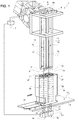
- the reference number 1 indicates, as a whole, a packaging station for inserting stacks of products 2 into packaging containers, defined by bags 3 ( figure 8 ).
- the stacked products have a flat shape.
- the stacked products to be packaged are defined by food products. In greater detail, they are sweet or savoury products, for example biscuits, possibly filled with a cream.
- the station 1 has a fixed structure 4 (shown partially and in a simplified view) and at least one robot 5 (partially illustrated), for example a robot of the anthropomorphic type.
- the robot 5 ends with an operating member 6 and is controlled by a control unit 7 to move the member 6 in space.
- the member 6 is secured to a frame 9, defined for example by a horizontal plate, supporting at least one housing 10, which is arranged below the frame 9, extends along a vertical axis 11 and ends with a lower inlet opening 12.
- the radial dimensions of the housing 10 are such as to be able to accommodate and vertically guide a corresponding stack of products 2, with a relatively small clearance.
- the cross-section of the housing 10 (with a cross-section plane orthogonal to the axis 11) is approximately the same size but slightly larger than the dimensions, in a plan view, of the stacked products.
- the cross-section of the housing 10 is constant along the axis 11, with the possible exception of an area at the lower end, i.e. at the opening 12, where the cross-section may be larger.
- the area at the lower end of the housing 10 has a flared shape so as to define an initially enlarged opening to facilitate entry of the stack of products 2.
- housings 10 are provided. Such housings 10 are parallel and arranged beside each other.
- each housing 10 is defined by a plurality of uprights or vertical bars 13, which are arranged around the axis 11 in positions which are spaced out from one another and project downwards from the frame 9.
- the lower ends of the uprights 13 have a tapered, pointed, or truncated cone shape in order to define the flared shape at the opening 12.
- each housing 10 is defined by four uprights 13. Even more preferably, two of the four uprights 13 are in common with the adjacent housing 10. In the specific example, a total of six uprights 13 are thus provided.
- the housings 10 are positioned above the structure 4, in such a way as to be aligned along the axes 11 with respective lifting devices 14 supported by the structure 4 in a manner not shown.
- Each device 14 comprises at least one vertical push rod 15, having an upper free end defined by a head 17, which has an upper bearing and pushing surface, indicated with the reference number 18 in the plan view in figure 5 .
- the head 17 is defined by a part made of softer material than that of the remaining part of the rod 15.
- the head 17 is made of a plastic material and is mounted on a metal stem.
- each device 14 comprises a pair of rods 15, parallel and spaced out from each other, simultaneously operated by the corresponding actuator 19.
- the rods 15 are arranged below a horizontal reference plane 20 of the structure 4, while in the raised position they project upwards with respect to the plane 20 (as shown in figure 2 ).
- the surfaces 18 of the two rods 15 are coplanar.
- the area of each surface 18 is greater than the cross-section of the remaining part of the rod 15. Overall, the area and the positions of the two surfaces 18 are established to project so as to be able to support the stack of products 2 in a stable manner.
- the station 1 has, for each housing 10, a supporting device 24 ( figure 4 ), which is carried directly or indirectly by the frame 9 and can be moved by the operation of at least one actuator 25 ( figures 1 and 6 ).
- the actuator 25 is also carried by the frame 9 and is controlled by the unit 7 in order to move the device 24 between a retracted position (in broken line in figure 4 ), in which the housing 10 and the opening 12 are open, and an extended position (continuous line in figure 4 ), in which the device 24 engages the opening 12 and/or a lower portion of the housing 10 and defines an upper surface 26 on which the stack of products 2 can rest after it has previously been inserted through the opening 12, as described in more detail below.
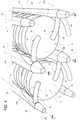
- the device 24 comprises two arms 27.
- the arms 27 associated with each housing 10 project horizontally from respective uprights 13a (forming part of the set of uprights 13), which are coupled to the frame 9 so as to be able to rotate about their vertical axes 28.
- the two uprights 13a are arranged in diametrically opposite positions with respect to the axis 11. Given that the arms 27 are fixed with respect to the uprights 13a, the rotation of the latter causes the arms 27 to be unfurled or furled in a horizontal plane between the retracted and extended positions.
- a transmission belt 30 is provided to transmit the rotation from a single actuator 25 to the uprights 13a.
- the actuator 25 is a linear actuator that operates a lever transmission (for example a connecting rod and crankshaft transmission).
- the actuator 25 is a rotary motor.
- the path of the transmission belt 30 extends in a manner not described in detail, in such a way as to rotate the two arms 27 of each housing 10 simultaneously and in opposite directions of rotation.
- the path of the transmission belt 30 extends in such a way as to rotate all four uprights 13a simultaneously, two in one direction and the other two in the opposite direction.
- the products to be packaged are transferred to the station 4 when they have already been stacked.
- the stacks of products 2 are arranged inside one or more auxiliary containers 34, which may be informally called “baskets” or “canisters".
- the containers 34 are transferred by a transport device 35, defined for example by a conveyor (shown partially and in a simplified way), to be positioned in the station 4 in the plane 20.
- Each container 34 has one or more vertical seats 36 which have respective upper openings 37 and are each engaged by a respective stack of products 2, with a relatively small clearance in the radial direction.
- the contour of the seats 36 is at least partly complementary to the shape, in plan view, of the products, in such a way as to keep the products stacked and vertically guide them.
- Figure 1 shows an example with seats 36 of circular shape, separated from each another, while figure 5 shows a variant of the shape, with two diametrically opposed recesses 38 for each seat 36 (in order to facilitate insertion of the products into the seats 36 during a previous stacking step).
- the number of seats 36 of each container 34 is equal to the number of devices 14 and/or housings 10 provided at the station 1.
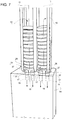
- the container 34 When it is transferred to station 4 by the device 35 ( figure 1 ), the container 34 is arranged, and preferably locked (in a manner not shown), in a reference position, between the plane 20 and the housings 10, in such a way as to align the seats 36 with the devices 14 and with the housings 10 along the axes 11. In this reference position, as shown in figure 3 , the openings 12 of the housings 10 are aligned and relatively close to the openings 37 of the seats 36. In other words, the robot 5 is controlled in such a way as to have a negligible gap vertically between the container 34 and the housings 10, which thus define an upward extension of the seats 36.
- the bottom of the seats 36 is defined by a perforated wall 39 of the container 34, on which the stacks of products 2 are placed.
- the holes of the walls 39 are designated by the reference number 40, pass vertically through the walls, and have number, dimensions and positions such as to be able to be traversed vertically by the rods 15 when the container 34 is arranged in the reference position. After container 34 has reached this position, and possibly has been locked, the rods 15 are operated so as to be raised.
- the heads 17 pass through an opening of the plane 20 and the holes 40, come into contact with the stack of products 2, and then cause the stack of products 2 to be raised so as to slide it along the seat 36 and insert it from below into the housing 10.
- the device 24 is arranged in its retracted position.
- the lifting ends when the stack of products 2 lies entirely inside the corresponding housing 10, at a height that is at least equal to that of the device 24.
- the stack of products 2 is raised to a height greater than that of the device 24.
- the device 24 is operated so as to be moved into the extended position.
- the shape and dimensions of the arms 27, as well as the shape, dimensions and positions of the heads 17, are designed so as to avoid interference between the various parts during movement into the extended position.
- the rods 15 are lowered by controlling the actuators 19 so as to move the stack of products 2 up to let it rest on the surface 26.
- the support of the stack of products 2 on the surface 26 can be obtained by lifting the frame 9, and therefore the device 24, by controlling the robot 5.
- the stack of products 2 is raised to the same height as the device 24. In this case, after operation of the device 24, it is not necessary to lower the heads 17 and/or raise the frame to support the stacks of products 2 by means of the surfaces 26 of the device 24.
- the robot 5 is operated so as to move the stacks of products 2 to a packaging area separate from the area where the devices 14 and the plane 20 are provided (i.e. separate from the area where the container 34 has been unloaded), and then to insert the stacks of products 2 into the bags 3.
- the container 34 can be moved away from the station 1.
- the frame 9 is moved so as to vertically align the housings 10 with an upper opening 41 of the bag 3.
- the frame 9 is lowered so as to insert the uprights 13 from above into the opening 41, while the bag 3 is maintained in an open configuration by means of gripping devices 42 schematically illustrated, of known type and not described in detail, and while the stacks of products 2 are supported by the surfaces 26 of the arms 27 (i.e. in the same configuration as shown in figure 7 ).
- a movement of the devices 42 can be provided, in a known and not shown manner, in order to arrange the bag 3 below the housings 10, and/or to align the opening 41 with the apertures 12 and/or to fit the bag 3 around the uprights 13 with an upward movement.
- the device 24 After insertion into the bag 3, the device 24 is moved into its retracted position by operating the actuator 25, to remove the lower support defined by the surface 26 of the arms 27, in a manner not shown.
- the stacks of products 2 are thus free to slide downwards under their own weight, along the housings 10.
- the opening 41 is sealed (for example by means of heat sealing or by means of a zipper device, not shown, forming part of the bag 3) to complete the packaging.
- the frame 9 is supported and moved by a moving and positioning device other than the robot 5; or the frame 9 is arranged in a fixed position with respect to the structure 4 (in this case, the insertion of the stacks of products 2 into the bag 3 is carried out by moving only the bag 3 after having removed the container 34).
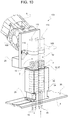
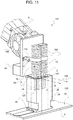
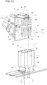
- FIGS 9 to 12 show a station 101, the parts of which are indicated, wherever possible, by using the same reference numbers used for the station 1 in figures 1 to 8 .
- the station 101 differs from the station 1 in some aspects. Firstly, the frame 9 is replaced by a different frame 109, which is devoid of the uprights 13 and the transmission 30 and, for example, is defined by a vertical plate.
- the housings 10 are defined by respective packaging containers 103 which are coupled to the frame 109 in fixed positions by means of a releasable retaining device 110, of a type known per se and not described in detail.
- the containers 103 are defined by respective rigid or semi-rigid plastic tubes and are positioned so as to have the same interaxial spacing between the seats 36 of the container 34.
- the inside diameter of the containers 103 is approximately the same size but slightly larger than the outer diameter of the products to be packaged.
- Each housing 10 has an axial end 112 which is opposite to the opening 12 along the corresponding axis 11 and is closed, for example by means of a wall 113 which constitutes part of the container 103 ( figure 9 ). According to a variant not shown, the end 112 is closed by a wall forming part of the frame 109.
- the device 24 differs from the solution of figures 1-8 , in that it comprises a respective tab 127 for each housing 10, instead of the two rotating arms 27.
- the upper surface of the tabs is indicated by the reference number 126, and performs the same function as the surface 26 of the solution of figures 1-8 .
- the tabs 127 In the extended position, the tabs 127 project along respective horizontal axes 128 at the opening 12, preferably without interference with the corresponding containers 103.
- the displacement of the tabs 127 between the retracted and extended positions is defined by a translational motion along the axes 128.
- all the tabs 127 are parts of a single plate supported and driven by a single actuator 25 (for example a linear actuator).
- each tab 127 has a width less than the distance between the two heads 17 of the corresponding device 14, so as to avoid interference when it is located between the heads 17.
- the rods 15 are lowered to release the container 34 (and then if necessary the latter is moved away, in a manner not shown), and the frame 109 is rotated by the robot 5 by an angle of 180° about a horizontal axis 130, for example parallel to the axes 128, so as to turn the containers 103 upside-down, i.e. to arrange the openings 12 upwards and the end 112 downwards. Thanks to being thus turned over, the stacks of products 2 rest by their own weight on the walls 113, and release the surfaces 126 from their weight.
- the tabs 127 are now moved into the retracted positions (in a manner not shown) to free up the openings 12, which can then be closed, for example by coupling respective caps (not shown) onto the containers 103.
- the containers 103 are decoupled from the frame 109, by releasing the device 110.
- the bags 3 and the containers 103 are sized so as to house the stacks of products 2 with very little clearance, thus achieving a saving in packaging material and a reduction in the risks of damage in the case of jolts and shocks after packaging.
- the method described above is extremely simple and requires a relatively small number of parts.
- the method can be adapted in order to package the stacks of products 2 in different types of packaging.
- the position and size of the heads 17 (and therefore of the holes 40) as shown in figures 2 and 5 are such that they can equally be used either at station 1 or at station 101.
- each container 34 can carry any number of stacks of products 2; in addition, it can carry stacks of products that are differently shaped and/or sized from each other to be packaged in different stations from each other (also at each station only one stack of products from among all those carried can be extracted from the container 34).
- the housing 10 may be defined by a different structure from the uprights 13.
- the device 24 could consist of movable elements with different shapes and of a different number with respect to that indicated above for the tabs 127 and the arms 27.
Landscapes
- Engineering & Computer Science (AREA)
- Mechanical Engineering (AREA)
- Container Filling Or Packaging Operations (AREA)
- Packaging Of Special Articles (AREA)
Applications Claiming Priority (1)
| Application Number | Priority Date | Filing Date | Title |
|---|---|---|---|
| LU100336A LU100336B1 (en) | 2017-07-12 | 2017-07-12 | Packaging method and packaging station for inserting stacks of products into packaging containers |
Publications (2)
| Publication Number | Publication Date |
|---|---|
| EP3428074A1 true EP3428074A1 (fr) | 2019-01-16 |
| EP3428074A8 EP3428074A8 (fr) | 2019-03-06 |
Family
ID=59506330
Family Applications (1)
| Application Number | Title | Priority Date | Filing Date |
|---|---|---|---|
| EP18183269.2A Withdrawn EP3428074A1 (fr) | 2017-07-12 | 2018-07-12 | Procédé d'emballage et poste d'emballage pour introduire des piles de produits dans des récipients d'emballage |
Country Status (2)
| Country | Link |
|---|---|
| EP (1) | EP3428074A1 (fr) |
| LU (1) | LU100336B1 (fr) |
Citations (5)
| Publication number | Priority date | Publication date | Assignee | Title |
|---|---|---|---|---|
| DE1017078B (de) * | 1954-06-22 | 1957-10-03 | Rose Brothers Ltd | Vorrichtung zum Verpacken von Biskuits od. dgl. in Beutel |
| US3273300A (en) * | 1963-08-07 | 1966-09-20 | Procter & Gamble | Continuous dough cutting and packaging |
| US4750317A (en) * | 1987-05-11 | 1988-06-14 | General Foods Inc. | Case packing apparatus |
| EP0476301A1 (fr) * | 1990-09-15 | 1992-03-25 | Natec Reich, Summer GmbH & Co. KG | Dispositif pour déposer des marchandises empilables, comme par exemple des tranches de fromage, ou de saucisson, des biscuits et produits similaires |
| EP1179476A2 (fr) * | 2000-03-29 | 2002-02-13 | SIG Pack Systems AG | Dispositif pour la mise en récipients cylindriques d'une pile de produits en forme de disques, particulièrement des pommes frites |
-
2017
- 2017-07-12 LU LU100336A patent/LU100336B1/en active IP Right Grant
-
2018
- 2018-07-12 EP EP18183269.2A patent/EP3428074A1/fr not_active Withdrawn
Patent Citations (5)
| Publication number | Priority date | Publication date | Assignee | Title |
|---|---|---|---|---|
| DE1017078B (de) * | 1954-06-22 | 1957-10-03 | Rose Brothers Ltd | Vorrichtung zum Verpacken von Biskuits od. dgl. in Beutel |
| US3273300A (en) * | 1963-08-07 | 1966-09-20 | Procter & Gamble | Continuous dough cutting and packaging |
| US4750317A (en) * | 1987-05-11 | 1988-06-14 | General Foods Inc. | Case packing apparatus |
| EP0476301A1 (fr) * | 1990-09-15 | 1992-03-25 | Natec Reich, Summer GmbH & Co. KG | Dispositif pour déposer des marchandises empilables, comme par exemple des tranches de fromage, ou de saucisson, des biscuits et produits similaires |
| EP1179476A2 (fr) * | 2000-03-29 | 2002-02-13 | SIG Pack Systems AG | Dispositif pour la mise en récipients cylindriques d'une pile de produits en forme de disques, particulièrement des pommes frites |
Also Published As
| Publication number | Publication date |
|---|---|
| LU100336B1 (en) | 2019-01-28 |
| EP3428074A8 (fr) | 2019-03-06 |
Similar Documents
| Publication | Publication Date | Title |
|---|---|---|
| EP3877296B1 (fr) | Système de stockage et de récupération automatisé | |
| US6056341A (en) | Apparatus for releasing items within a confined space | |
| EP1318074B1 (fr) | Dispositif de remplissage de boîtes avec des objects en plusieurs rangées | |
| US9926147B2 (en) | Stacking device and stacking method | |
| EP2995561B1 (fr) | Appareil pour mettre en boite des articles rectangulaires | |
| US8074431B1 (en) | Hybrid palletizer | |
| US20160107782A1 (en) | Apparatus and method for handling articles | |
| EP1602580B1 (fr) | Machine de mise en boîte semi-automatique. | |
| EP1553021A1 (fr) | Dispositif et procédé de remplissage d'une boíte | |
| EP2709917B1 (fr) | Appareil et procédé pour l'ouverture totalement automatique de caisses pour produits agricoles | |
| KR102012928B1 (ko) | 포장용기 적재장치 | |
| US12595129B2 (en) | Station for presenting containers | |
| FR2543513A1 (fr) | Machine a palettiser pour recipients | |
| EP1410995A1 (fr) | Machine pour remplir des cartons contenant des bouteilles séparées par des cloisonnements | |
| CN113581507B (zh) | 一种食品自动包装设备 | |
| EP3428074A1 (fr) | Procédé d'emballage et poste d'emballage pour introduire des piles de produits dans des récipients d'emballage | |
| EP4069615B1 (fr) | Procédé de fabrication de récipients à partir de cartouches à blanc | |
| US12286313B2 (en) | Transfer apparatus and process | |
| KR102221269B1 (ko) | 포장박스의 제품 포장장치 | |
| WO2014182168A1 (fr) | Empileur de caisse | |
| EP4227246A1 (fr) | Installation de manipulation de feuilles de carton ou analogue | |
| CN110654613B (zh) | 一种预制菜流水线自动堆叠设备 | |
| JP6043509B2 (ja) | 箱詰め装置 | |
| US12286312B2 (en) | Clamp device and related transfer apparatus | |
| US20260028142A1 (en) | Apparatus for filling gyoza in round tray and method of the same |
Legal Events
| Date | Code | Title | Description |
|---|---|---|---|
| PUAI | Public reference made under article 153(3) epc to a published international application that has entered the european phase |
Free format text: ORIGINAL CODE: 0009012 |
|
| STAA | Information on the status of an ep patent application or granted ep patent |
Free format text: STATUS: THE APPLICATION HAS BEEN PUBLISHED |
|
| AK | Designated contracting states |
Kind code of ref document: A1 Designated state(s): AL AT BE BG CH CY CZ DE DK EE ES FI FR GB GR HR HU IE IS IT LI LT LU LV MC MK MT NL NO PL PT RO RS SE SI SK SM TR |
|
| AX | Request for extension of the european patent |
Extension state: BA ME |
|
| RAP1 | Party data changed (applicant data changed or rights of an application transferred) |
Owner name: SOREMARTEC SA |
|
| STAA | Information on the status of an ep patent application or granted ep patent |
Free format text: STATUS: REQUEST FOR EXAMINATION WAS MADE |
|
| 17P | Request for examination filed |
Effective date: 20190716 |
|
| RBV | Designated contracting states (corrected) |
Designated state(s): AL AT BE BG CH CY CZ DE DK EE ES FI FR GB GR HR HU IE IS IT LI LT LU LV MC MK MT NL NO PL PT RO RS SE SI SK SM TR |
|
| STAA | Information on the status of an ep patent application or granted ep patent |
Free format text: STATUS: EXAMINATION IS IN PROGRESS |
|
| 17Q | First examination report despatched |
Effective date: 20191111 |
|
| GRAP | Despatch of communication of intention to grant a patent |
Free format text: ORIGINAL CODE: EPIDOSNIGR1 |
|
| STAA | Information on the status of an ep patent application or granted ep patent |
Free format text: STATUS: GRANT OF PATENT IS INTENDED |
|
| INTG | Intention to grant announced |
Effective date: 20200812 |
|
| STAA | Information on the status of an ep patent application or granted ep patent |
Free format text: STATUS: THE APPLICATION IS DEEMED TO BE WITHDRAWN |
|
| 18D | Application deemed to be withdrawn |
Effective date: 20201223 |