EP1179476A2 - Dispositif pour la mise en récipients cylindriques d'une pile de produits en forme de disques, particulièrement des pommes frites - Google Patents
Dispositif pour la mise en récipients cylindriques d'une pile de produits en forme de disques, particulièrement des pommes frites Download PDFInfo
- Publication number
- EP1179476A2 EP1179476A2 EP01810276A EP01810276A EP1179476A2 EP 1179476 A2 EP1179476 A2 EP 1179476A2 EP 01810276 A EP01810276 A EP 01810276A EP 01810276 A EP01810276 A EP 01810276A EP 1179476 A2 EP1179476 A2 EP 1179476A2
- Authority
- EP
- European Patent Office
- Prior art keywords
- station
- container
- containers
- intermediate container
- stack
- Prior art date
- Legal status (The legal status is an assumption and is not a legal conclusion. Google has not performed a legal analysis and makes no representation as to the accuracy of the status listed.)
- Granted
Links
Images




Classifications
-
- B—PERFORMING OPERATIONS; TRANSPORTING
- B65—CONVEYING; PACKING; STORING; HANDLING THIN OR FILAMENTARY MATERIAL
- B65B—MACHINES, APPARATUS OR DEVICES FOR, OR METHODS OF, PACKAGING ARTICLES OR MATERIALS; UNPACKING
- B65B5/00—Packaging individual articles in containers or receptacles, e.g. bags, sacks, boxes, cartons, cans, jars
- B65B5/06—Packaging groups of articles, the groups being treated as single articles
- B65B5/064—Potato chips
Definitions
- From US-A-4 052 838 is a device for packaging Stacking flat-shaped, disc-shaped products, namely potato chips, in tubular packaging containers known.
- On a downward sloping vibrating trough a continuous flow of products promoted.
- lances which product stacks are formed alternately.
- a separated stack slides into one of a star shape on one Turnstile arranged tubes. Once this is filled the turnstile becomes a step around a horizontal axis turned further.
- the pipe a container closed on one side with a bottom.
- the container must be one have a larger diameter than actually to accommodate the Products would be required.
- the stack slides into the tube can tip the front slices of the stack, causing too Interference leads because there is no longer space for the entire stack in the pipe Has. This also results in underweight packs. These have to be eliminated.
- the present invention has for its object a device of the above type in such a way that the aforementioned Disadvantages are avoided. This task is accomplished by the Combination of features of the claims solved.
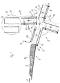
- the device according to FIGS. 1-8 comprises a feed conveyor 9, for example a vibrating trough on which a strand 10 is scale-like Products 11 lying on the flat side, in particular Potato chips, always delivered in a conveying direction A. become.
- the products 11 are stowed at a first station 12, so that they line up.
- the device comprises one Intermediate conveyor 13 in the form of a horizontal axis 14, rotatable turntable 15. There are four on the turntable 15 Rotational axes 16 rotatably mounted.
- the axes 16 are parallel to Axis 14 and are all the same distance from it.
- On each Axis 16 an intermediate container 17 is attached.
- any intermediate container 17 is assigned a holding element, comprising a on the container 17 rotatably mounted shaft 18, of which two holding fingers 19, 20 stand out.
- One finger 19 is at the outer end of the intermediate container 17 firmly connected to the shaft 18.
- the other finger 20 is longitudinally displaceable and lockable on the shaft 18, around the finger spacing of the height of the stack to be formed 27 to adapt.
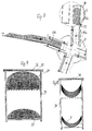
- the intermediate container 17 consist of two prismatic container parts 21, concave on their facing sides and are at a distance from each other. In the one shown in FIG Rotational position of the shaft 18 are the ends of the fingers 19, 20 outside, in the other rotational position ( Figure 13) within the Internal cross section of the container 17th
- a pickup floor 25 is on the rail 24 displaceable from a by means of a motor, not shown fixed, shown in Figure 1 extended position in a adjustable basic position shown in Figure 4.
- Above the conveyor 10 is at its downstream end a transverse to Delivery direction A by means of another motor, not shown Slidable separating sword 26 which each after the lifting of the pick-up floor 25 from its extended Position in the position of Figure 3 is lowered and thus a stack 27 of potato chips within the intermediate container 17 separates.
- the shaft 18 is rotated, so that the holding fingers 19, 20 from the position shown in Figure 12 get into that of Figure 13 and thus the stack 27 between to lock myself in.
- the turntable 15 is then rotated, so that the filled intermediate container 17 into the second Station 30 arrives.
- the filled one becomes simultaneously Intermediate container 17 rotated about the axis of rotation 16 such that at the second station 30, the immovable holding finger 19 is below.
- the second station 30 there is also a guide rail 31 fixed to the frame.
- a Pusher 32 by means of a motor, not shown, from the 1 and 6 position shown in the position of Figure 8 displaceable.
- a discharge conveyor arranged in the form of a further turntable 33.
- On the plate 33 are two holding elements, not shown, for filling, cylindrical container 34 arranged.
- the empty containers 34 are at one end by a sealed film 35 and one Cover 36 closed.
- the turntable 33 can be rotated by 180 ° in each case.
- the second Station 30 has a container 34 with its filling opening down ready to fill a stack 27.
- On the on the other side of the turntable 33 becomes a filled container 34 against an empty container 34 by means not shown exchanged, for example by grippers.
- the filled container 34 is then closed by a flanged bottom 37 ( Figures 9 and 10).
- Figures 1-8 is the functional sequence when operating the device shown schematically.
- Figure 1 shows the starting position, in which the strand 10 jammed on the extended pick-up floor 25 is.
- the separation sword 26 is in the raised position.
- one the intermediate container 17a is in the first station 12 in Extension of the conveyor 9. Its holding fingers 19, 20 are in the disengaged position according to FIG. 12.
- Figure 2 shows the movement of the pick-up floor 25 when filling the Products 11 in the intermediate container 17a.
- the separating sword 26 lowered and thus a stack 27 separated from the strand 10 (FIG 3).
- the stack 27 is completely within the intermediate container 17a.
- the shaft 18a in question is rotated, so that the fingers 19a, 20a engage inside the container 17a and enclose the separated stack 27 between them.
- FIG. 11 and 14 can on the same shaft or axis 16 each several intermediate containers 17 side by side to be ordered.
- the shafts 18 are each on a container part 21 assembled in pairs. For example, you can use a toothed belt 43 and a motor 44 together from the part 21a shown in the indented position in the other parts 21b shown extended position of the holding fingers 19, 20th be pivoted.
- Figure 14 shows schematically a possible variant of the training of the turntable 15, which in this case consists of two disks 46, which are rigidly connected to the axis 14.
- the axis 14 is driven by a motor 47. Outside the windows 46 is on the axis 14 a sleeve 48 with two sprockets 49, 50 rotatably mounted.
- One ring gear 49 meshes with one Gear 51, which is driven permanently by a motor 52.
- the two gear wheels 51 rotate in opposite directions.
- the other ring gear 50 meshes with four rotatably mounted on the four axes of rotation 16 Gears 53.
- These gears 53 are associated with the Rotation axes 16 each via an individually switchable clutch-brake unit 54 connected.
- Such clutch-brake units are known for example from manual gearboxes of motor vehicles.
- the units 54 can be switched in three positions, namely in a first position, in which the axis of rotation 16 with the Disc 46 is coupled, a second position in which it is coupled to the gear 53 and in an intermediate position, in which the axis 16 can rotate freely.
- the control of the Units 54 can take place, for example, via limit switches 58, 59, which are mounted on the disks 46.
- One limit switch 58 interacts with a frame-fixed cam 60, which immediately is arranged after the first station 12 and the relevant unit 54 assigned to one motor 52 into the second Position and the second unit 54 of the same shaft 16 in the Intermediate position switches.
- the described device has the following advantages in particular: cylindrical or saddle-shaped products like potato chips can as a scale-like strand 10 only in that shown in Figures 1-8 Position in which their convex Side is directed against the conveying direction A.
- would one such strand filled directly into the container 34 would be the convex side of the products 11 directed against the cover 36.
- the inventive Rotational movement of the intermediate container 17 relative to Turntable 15 between stations 12 and 30 becomes this disadvantage avoided.
- the same advantage can also arise with Filling of other products lying flat against one another, for Example biscuits with a one-sided chocolate top layer, which in the Container 34 should face the lid 36.
- the device according to the invention is therefore versatile in Application. It enables gentle handling of the products 11, especially during the turning process. It will be a safe one Filling of the container reached because the products 11 tilted one end of the stack 27 is safely avoided. A potential Contamination of the sealing area by product components is avoided. Due to the simultaneous rotation of the intermediate container from the first to the second station and the Rotary movement of the intermediate container from the second to the first Station (reverse rotation) high performance is achieved.
Landscapes
- Engineering & Computer Science (AREA)
- Mechanical Engineering (AREA)
- Feeding Of Articles To Conveyors (AREA)
Applications Claiming Priority (4)
| Application Number | Priority Date | Filing Date | Title |
|---|---|---|---|
| CH6082000 | 2000-03-29 | ||
| CH6082000 | 2000-03-29 | ||
| CH29032000 | 2000-08-06 | ||
| CH290300 | 2000-08-06 |
Publications (4)
| Publication Number | Publication Date |
|---|---|
| EP1179476A2 true EP1179476A2 (fr) | 2002-02-13 |
| EP1179476A8 EP1179476A8 (fr) | 2002-05-08 |
| EP1179476A3 EP1179476A3 (fr) | 2002-07-31 |
| EP1179476B1 EP1179476B1 (fr) | 2003-10-01 |
Family
ID=25737708
Family Applications (1)
| Application Number | Title | Priority Date | Filing Date |
|---|---|---|---|
| EP20010810276 Expired - Lifetime EP1179476B1 (fr) | 2000-03-29 | 2001-03-20 | Dispositif pour la mise en récipients cylindriques d'une pile de produits en forme de disques, particulièrement des pommes chips |
Country Status (1)
| Country | Link |
|---|---|
| EP (1) | EP1179476B1 (fr) |
Cited By (4)
| Publication number | Priority date | Publication date | Assignee | Title |
|---|---|---|---|---|
| EP1473234A1 (fr) * | 2003-05-02 | 2004-11-03 | Alcan Technology & Management AG | Dispositif d'empaquetage pour le conditionnement de piles d'articles plats |
| EP3428074A1 (fr) * | 2017-07-12 | 2019-01-16 | Soremartec S.A. | Procédé d'emballage et poste d'emballage pour introduire des piles de produits dans des récipients d'emballage |
| GB2540429B (en) * | 2015-07-17 | 2020-04-01 | Frito Lay Trading Co Gmbh | Packaging snack food chips |
| WO2023213490A1 (fr) * | 2022-05-06 | 2023-11-09 | Hastamat Verpackungstechnik Gmbh + Co. Kg | Unité de retournement et procédé pour retourner un récipient ouvert contenant des produits plats et système et procédé pour lé remplissage en portions de produits plats |
Citations (1)
| Publication number | Priority date | Publication date | Assignee | Title |
|---|---|---|---|---|
| US4052838A (en) | 1976-05-04 | 1977-10-11 | Frito-Lay, Inc. | Apparatus for packaging nested, uniformly shaped articles |
-
2001
- 2001-03-20 EP EP20010810276 patent/EP1179476B1/fr not_active Expired - Lifetime
Patent Citations (1)
| Publication number | Priority date | Publication date | Assignee | Title |
|---|---|---|---|---|
| US4052838A (en) | 1976-05-04 | 1977-10-11 | Frito-Lay, Inc. | Apparatus for packaging nested, uniformly shaped articles |
Cited By (6)
| Publication number | Priority date | Publication date | Assignee | Title |
|---|---|---|---|---|
| EP1473234A1 (fr) * | 2003-05-02 | 2004-11-03 | Alcan Technology & Management AG | Dispositif d'empaquetage pour le conditionnement de piles d'articles plats |
| DE10319707B3 (de) * | 2003-05-02 | 2004-11-25 | Alcan Technology & Management Ag | Verpackungseinrichtung |
| GB2540429B (en) * | 2015-07-17 | 2020-04-01 | Frito Lay Trading Co Gmbh | Packaging snack food chips |
| EP3428074A1 (fr) * | 2017-07-12 | 2019-01-16 | Soremartec S.A. | Procédé d'emballage et poste d'emballage pour introduire des piles de produits dans des récipients d'emballage |
| LU100336B1 (en) * | 2017-07-12 | 2019-01-28 | Soremartec Sa | Packaging method and packaging station for inserting stacks of products into packaging containers |
| WO2023213490A1 (fr) * | 2022-05-06 | 2023-11-09 | Hastamat Verpackungstechnik Gmbh + Co. Kg | Unité de retournement et procédé pour retourner un récipient ouvert contenant des produits plats et système et procédé pour lé remplissage en portions de produits plats |
Also Published As
| Publication number | Publication date |
|---|---|
| EP1179476B1 (fr) | 2003-10-01 |
| EP1179476A8 (fr) | 2002-05-08 |
| EP1179476A3 (fr) | 2002-07-31 |
Similar Documents
| Publication | Publication Date | Title |
|---|---|---|
| EP0372314B1 (fr) | Dispositif pour le retournement d'un emballage | |
| EP0490084A2 (fr) | Dispositif pour l'emballage ou le déballage de récipients | |
| EP0312490B1 (fr) | Procédé et dispositif pour former et transporter des groupes de produits alimentaires plats empilables, en particulier des biscuits | |
| CH676955A5 (fr) | ||
| DE4441680B4 (de) | Verfahren und Vorrichtung zum Herstellen von Zwillings-Zigarettenpackungen | |
| DE102013215233A1 (de) | Beladeteller einer Beschickungsanlage für eine Verpackungsmaschine für Süßwaren | |
| DE3221862A1 (de) | Vorrichtung zum zufuehren von behaeltern oder schachteln in einer auf zwei gegenueberliegenden seiten durchgehend geoeffneten form | |
| EP1302419B1 (fr) | Procédé et dispositif d' application définie de produits sur une chaîne transporteuse en forme d' éventail | |
| EP1179476B1 (fr) | Dispositif pour la mise en récipients cylindriques d'une pile de produits en forme de disques, particulièrement des pommes chips | |
| EP1521532A1 (fr) | Dispositif servant a inserer des batonnets dans des moules pour produire des confiseries sur batonnet | |
| DE1761814C3 (de) | Vorrichtung zum Vereinzeln und Überführen von ineinander gestapelten Behältern | |
| DE2900615C2 (fr) | ||
| DE69504921T2 (de) | Stapelvorrichtung für scheibenförmige Gegenstände | |
| DE102017104098A1 (de) | Kapselverpackungssystem | |
| DE3444516C2 (de) | Verpackungsmaschine | |
| DE852070C (de) | Spinn- oder Zwirnmaschine mit einer Vorrichtung zum Absetzen der vollen Garnkoerper | |
| DE4333085A1 (de) | Verfahren und Vorrichtung zur Herstellung von Kartons mit Zigaretten | |
| DE3637232C2 (fr) | ||
| EP0599232B1 (fr) | Dispositif pour emballer des articles individuels en portions | |
| DE4406089A1 (de) | Verfahren und Vorrichtung zum Abfüllen von Tabletten oder dergleichen in Tablettenröhrchen | |
| DE2401193C3 (de) | Vorrichtung zum geordneten Einbringen von Schlauchbeuteln in einen Versandkasten | |
| EP1657190A1 (fr) | Dispositif de saisie et délivrance d'objets | |
| DE2250682A1 (de) | Vorrichtung zum ueberfuehren mehrerer gegenstaende in einen verpackungskarton | |
| DE19728402C2 (de) | Vorrichtung zum Ausrichten von zylindrischen Gegenständen | |
| DE2523242A1 (de) | Zuliefervorrichtung fuer eine verpackungsmaschine |
Legal Events
| Date | Code | Title | Description |
|---|---|---|---|
| PUAI | Public reference made under article 153(3) epc to a published international application that has entered the european phase |
Free format text: ORIGINAL CODE: 0009012 |
|
| AK | Designated contracting states |
Kind code of ref document: A2 Designated state(s): AT BE CH CY DE DK ES FI FR GB GR IE IT LI LU MC NL PT SE TR |
|
| AX | Request for extension of the european patent |
Free format text: AL;LT;LV;MK;RO;SI |
|
| PUAL | Search report despatched |
Free format text: ORIGINAL CODE: 0009013 |
|
| AX | Request for extension of the european patent |
Free format text: AL;LT;LV;MK;RO;SI |
|
| RIC1 | Information provided on ipc code assigned before grant |
Free format text: 7B 65B 5/06 A, 7B 65B 23/16 B |
|
| 17P | Request for examination filed |
Effective date: 20020817 |
|
| GRAH | Despatch of communication of intention to grant a patent |
Free format text: ORIGINAL CODE: EPIDOS IGRA |
|
| GRAH | Despatch of communication of intention to grant a patent |
Free format text: ORIGINAL CODE: EPIDOS IGRA |
|
| AKX | Designation fees paid |
Designated state(s): AT BE CH CY DE DK ES FI FR GB GR IE IT LI LU MC NL PT SE TR |
|
| GRAA | (expected) grant |
Free format text: ORIGINAL CODE: 0009210 |
|
| AK | Designated contracting states |
Kind code of ref document: B1 Designated state(s): AT BE CH CY DE DK ES FI FR GB GR IE IT LI LU MC NL PT SE TR |
|
| PG25 | Lapsed in a contracting state [announced via postgrant information from national office to epo] |
Ref country code: TR Free format text: LAPSE BECAUSE OF FAILURE TO SUBMIT A TRANSLATION OF THE DESCRIPTION OR TO PAY THE FEE WITHIN THE PRESCRIBED TIME-LIMIT Effective date: 20031001 Ref country code: NL Free format text: LAPSE BECAUSE OF FAILURE TO SUBMIT A TRANSLATION OF THE DESCRIPTION OR TO PAY THE FEE WITHIN THE PRESCRIBED TIME-LIMIT Effective date: 20031001 Ref country code: IE Free format text: LAPSE BECAUSE OF FAILURE TO SUBMIT A TRANSLATION OF THE DESCRIPTION OR TO PAY THE FEE WITHIN THE PRESCRIBED TIME-LIMIT Effective date: 20031001 Ref country code: FR Free format text: LAPSE BECAUSE OF FAILURE TO SUBMIT A TRANSLATION OF THE DESCRIPTION OR TO PAY THE FEE WITHIN THE PRESCRIBED TIME-LIMIT Effective date: 20031001 Ref country code: FI Free format text: LAPSE BECAUSE OF FAILURE TO SUBMIT A TRANSLATION OF THE DESCRIPTION OR TO PAY THE FEE WITHIN THE PRESCRIBED TIME-LIMIT Effective date: 20031001 Ref country code: CY Free format text: LAPSE BECAUSE OF FAILURE TO SUBMIT A TRANSLATION OF THE DESCRIPTION OR TO PAY THE FEE WITHIN THE PRESCRIBED TIME-LIMIT Effective date: 20031001 |
|
| REG | Reference to a national code |
Ref country code: GB Ref legal event code: FG4D Free format text: NOT ENGLISH |
|
| REG | Reference to a national code |
Ref country code: CH Ref legal event code: NV Representative=s name: ISLER & PEDRAZZINI AG Ref country code: CH Ref legal event code: EP |
|
| REG | Reference to a national code |
Ref country code: IE Ref legal event code: FG4D Free format text: GERMAN |
|
| REF | Corresponds to: |
Ref document number: 50100700 Country of ref document: DE Date of ref document: 20031106 Kind code of ref document: P |
|
| GBT | Gb: translation of ep patent filed (gb section 77(6)(a)/1977) |
Effective date: 20031117 |
|
| PG25 | Lapsed in a contracting state [announced via postgrant information from national office to epo] |
Ref country code: SE Free format text: LAPSE BECAUSE OF FAILURE TO SUBMIT A TRANSLATION OF THE DESCRIPTION OR TO PAY THE FEE WITHIN THE PRESCRIBED TIME-LIMIT Effective date: 20040101 Ref country code: GR Free format text: LAPSE BECAUSE OF FAILURE TO SUBMIT A TRANSLATION OF THE DESCRIPTION OR TO PAY THE FEE WITHIN THE PRESCRIBED TIME-LIMIT Effective date: 20040101 Ref country code: DK Free format text: LAPSE BECAUSE OF FAILURE TO SUBMIT A TRANSLATION OF THE DESCRIPTION OR TO PAY THE FEE WITHIN THE PRESCRIBED TIME-LIMIT Effective date: 20040101 |
|
| NLV1 | Nl: lapsed or annulled due to failure to fulfill the requirements of art. 29p and 29m of the patents act | ||
| PG25 | Lapsed in a contracting state [announced via postgrant information from national office to epo] |
Ref country code: LU Free format text: LAPSE BECAUSE OF NON-PAYMENT OF DUE FEES Effective date: 20040320 Ref country code: AT Free format text: LAPSE BECAUSE OF NON-PAYMENT OF DUE FEES Effective date: 20040320 |
|
| PG25 | Lapsed in a contracting state [announced via postgrant information from national office to epo] |
Ref country code: MC Free format text: LAPSE BECAUSE OF NON-PAYMENT OF DUE FEES Effective date: 20040331 Ref country code: BE Free format text: LAPSE BECAUSE OF NON-PAYMENT OF DUE FEES Effective date: 20040331 |
|
| REG | Reference to a national code |
Ref country code: ES Ref legal event code: FG2A Ref document number: 2208537 Country of ref document: ES Kind code of ref document: T3 |
|
| REG | Reference to a national code |
Ref country code: IE Ref legal event code: FD4D |
|
| PLBE | No opposition filed within time limit |
Free format text: ORIGINAL CODE: 0009261 |
|
| STAA | Information on the status of an ep patent application or granted ep patent |
Free format text: STATUS: NO OPPOSITION FILED WITHIN TIME LIMIT |
|
| 26N | No opposition filed |
Effective date: 20040702 |
|
| BERE | Be: lapsed |
Owner name: *SIG PACK SYSTEMS A.G. Effective date: 20040331 |
|
| EN | Fr: translation not filed | ||
| PGFP | Annual fee paid to national office [announced via postgrant information from national office to epo] |
Ref country code: GB Payment date: 20050307 Year of fee payment: 5 |
|
| PGFP | Annual fee paid to national office [announced via postgrant information from national office to epo] |
Ref country code: CH Payment date: 20050323 Year of fee payment: 5 |
|
| PGFP | Annual fee paid to national office [announced via postgrant information from national office to epo] |
Ref country code: ES Payment date: 20050413 Year of fee payment: 5 |
|
| PGFP | Annual fee paid to national office [announced via postgrant information from national office to epo] |
Ref country code: DE Payment date: 20050513 Year of fee payment: 5 |
|
| PG25 | Lapsed in a contracting state [announced via postgrant information from national office to epo] |
Ref country code: GB Free format text: LAPSE BECAUSE OF NON-PAYMENT OF DUE FEES Effective date: 20060320 |
|
| PG25 | Lapsed in a contracting state [announced via postgrant information from national office to epo] |
Ref country code: ES Free format text: LAPSE BECAUSE OF NON-PAYMENT OF DUE FEES Effective date: 20060321 |
|
| PG25 | Lapsed in a contracting state [announced via postgrant information from national office to epo] |
Ref country code: LI Free format text: LAPSE BECAUSE OF NON-PAYMENT OF DUE FEES Effective date: 20060331 Ref country code: CH Free format text: LAPSE BECAUSE OF NON-PAYMENT OF DUE FEES Effective date: 20060331 |
|
| PGFP | Annual fee paid to national office [announced via postgrant information from national office to epo] |
Ref country code: IT Payment date: 20060331 Year of fee payment: 6 |
|
| PG25 | Lapsed in a contracting state [announced via postgrant information from national office to epo] |
Ref country code: DE Free format text: LAPSE BECAUSE OF NON-PAYMENT OF DUE FEES Effective date: 20061003 |
|
| REG | Reference to a national code |
Ref country code: CH Ref legal event code: PL |
|
| GBPC | Gb: european patent ceased through non-payment of renewal fee |
Effective date: 20060320 |
|
| REG | Reference to a national code |
Ref country code: ES Ref legal event code: FD2A Effective date: 20060321 |
|
| PG25 | Lapsed in a contracting state [announced via postgrant information from national office to epo] |
Ref country code: PT Free format text: LAPSE BECAUSE OF NON-PAYMENT OF DUE FEES Effective date: 20040301 |
|
| PG25 | Lapsed in a contracting state [announced via postgrant information from national office to epo] |
Ref country code: IT Free format text: LAPSE BECAUSE OF NON-PAYMENT OF DUE FEES Effective date: 20070320 |