EP3428097A1 - Spule aus thermoplastischem material und verfahren zu ihrer herstellung - Google Patents
Spule aus thermoplastischem material und verfahren zu ihrer herstellung Download PDFInfo
- Publication number
- EP3428097A1 EP3428097A1 EP17209031.8A EP17209031A EP3428097A1 EP 3428097 A1 EP3428097 A1 EP 3428097A1 EP 17209031 A EP17209031 A EP 17209031A EP 3428097 A1 EP3428097 A1 EP 3428097A1
- Authority
- EP
- European Patent Office
- Prior art keywords
- coil
- flange
- annular
- core
- annular wall
- Prior art date
- Legal status (The legal status is an assumption and is not a legal conclusion. Google has not performed a legal analysis and makes no representation as to the accuracy of the status listed.)
- Granted
Links
Images


Classifications
-
- B—PERFORMING OPERATIONS; TRANSPORTING
- B65—CONVEYING; PACKING; STORING; HANDLING THIN OR FILAMENTARY MATERIAL
- B65H—HANDLING THIN OR FILAMENTARY MATERIAL, e.g. SHEETS, WEBS, CABLES
- B65H75/00—Storing webs, tapes, or filamentary material, e.g. on reels
- B65H75/02—Cores, formers, supports, or holders for coiled, wound, or folded material, e.g. reels, spindles, bobbins, cop tubes, cans, mandrels or chucks
- B65H75/04—Kinds or types
- B65H75/08—Kinds or types of circular or polygonal cross-section
- B65H75/14—Kinds or types of circular or polygonal cross-section with two end flanges
-
- B—PERFORMING OPERATIONS; TRANSPORTING
- B23—MACHINE TOOLS; METAL-WORKING NOT OTHERWISE PROVIDED FOR
- B23K—SOLDERING OR UNSOLDERING; WELDING; CLADDING OR PLATING BY SOLDERING OR WELDING; CUTTING BY APPLYING HEAT LOCALLY, e.g. FLAME CUTTING; WORKING BY LASER BEAM
- B23K20/00—Non-electric welding by applying impact or other pressure, with or without the application of heat, e.g. cladding or plating
- B23K20/12—Non-electric welding by applying impact or other pressure, with or without the application of heat, e.g. cladding or plating the heat being generated by friction; Friction welding
- B23K20/129—Non-electric welding by applying impact or other pressure, with or without the application of heat, e.g. cladding or plating the heat being generated by friction; Friction welding specially adapted for particular articles or work
-
- B—PERFORMING OPERATIONS; TRANSPORTING
- B29—WORKING OF PLASTICS; WORKING OF SUBSTANCES IN A PLASTIC STATE IN GENERAL
- B29C—SHAPING OR JOINING OF PLASTICS; SHAPING OF MATERIAL IN A PLASTIC STATE, NOT OTHERWISE PROVIDED FOR; AFTER-TREATMENT OF THE SHAPED PRODUCTS, e.g. REPAIRING
- B29C65/00—Joining or sealing of preformed parts, e.g. welding of plastics materials; Apparatus therefor
- B29C65/02—Joining or sealing of preformed parts, e.g. welding of plastics materials; Apparatus therefor by heating, with or without pressure
- B29C65/08—Joining or sealing of preformed parts, e.g. welding of plastics materials; Apparatus therefor by heating, with or without pressure using ultrasonic vibrations
-
- B—PERFORMING OPERATIONS; TRANSPORTING
- B29—WORKING OF PLASTICS; WORKING OF SUBSTANCES IN A PLASTIC STATE IN GENERAL
- B29C—SHAPING OR JOINING OF PLASTICS; SHAPING OF MATERIAL IN A PLASTIC STATE, NOT OTHERWISE PROVIDED FOR; AFTER-TREATMENT OF THE SHAPED PRODUCTS, e.g. REPAIRING
- B29C65/00—Joining or sealing of preformed parts, e.g. welding of plastics materials; Apparatus therefor
- B29C65/02—Joining or sealing of preformed parts, e.g. welding of plastics materials; Apparatus therefor by heating, with or without pressure
- B29C65/10—Joining or sealing of preformed parts, e.g. welding of plastics materials; Apparatus therefor by heating, with or without pressure using hot gases (e.g. combustion gases) or flames coming in contact with at least one of the parts to be joined
-
- B—PERFORMING OPERATIONS; TRANSPORTING
- B29—WORKING OF PLASTICS; WORKING OF SUBSTANCES IN A PLASTIC STATE IN GENERAL
- B29C—SHAPING OR JOINING OF PLASTICS; SHAPING OF MATERIAL IN A PLASTIC STATE, NOT OTHERWISE PROVIDED FOR; AFTER-TREATMENT OF THE SHAPED PRODUCTS, e.g. REPAIRING
- B29C65/00—Joining or sealing of preformed parts, e.g. welding of plastics materials; Apparatus therefor
- B29C65/02—Joining or sealing of preformed parts, e.g. welding of plastics materials; Apparatus therefor by heating, with or without pressure
- B29C65/14—Joining or sealing of preformed parts, e.g. welding of plastics materials; Apparatus therefor by heating, with or without pressure using wave energy, i.e. electromagnetic radiation, or particle radiation
- B29C65/1403—Joining or sealing of preformed parts, e.g. welding of plastics materials; Apparatus therefor by heating, with or without pressure using wave energy, i.e. electromagnetic radiation, or particle radiation characterised by the type of electromagnetic or particle radiation
- B29C65/1412—Infrared [IR] radiation
-
- B—PERFORMING OPERATIONS; TRANSPORTING
- B29—WORKING OF PLASTICS; WORKING OF SUBSTANCES IN A PLASTIC STATE IN GENERAL
- B29C—SHAPING OR JOINING OF PLASTICS; SHAPING OF MATERIAL IN A PLASTIC STATE, NOT OTHERWISE PROVIDED FOR; AFTER-TREATMENT OF THE SHAPED PRODUCTS, e.g. REPAIRING
- B29C65/00—Joining or sealing of preformed parts, e.g. welding of plastics materials; Apparatus therefor
- B29C65/02—Joining or sealing of preformed parts, e.g. welding of plastics materials; Apparatus therefor by heating, with or without pressure
- B29C65/18—Joining or sealing of preformed parts, e.g. welding of plastics materials; Apparatus therefor by heating, with or without pressure using heated tools
- B29C65/20—Joining or sealing of preformed parts, e.g. welding of plastics materials; Apparatus therefor by heating, with or without pressure using heated tools with direct contact, e.g. using "mirror"
-
- B—PERFORMING OPERATIONS; TRANSPORTING
- B29—WORKING OF PLASTICS; WORKING OF SUBSTANCES IN A PLASTIC STATE IN GENERAL
- B29C—SHAPING OR JOINING OF PLASTICS; SHAPING OF MATERIAL IN A PLASTIC STATE, NOT OTHERWISE PROVIDED FOR; AFTER-TREATMENT OF THE SHAPED PRODUCTS, e.g. REPAIRING
- B29C65/00—Joining or sealing of preformed parts, e.g. welding of plastics materials; Apparatus therefor
- B29C65/48—Joining or sealing of preformed parts, e.g. welding of plastics materials; Apparatus therefor using adhesives, i.e. using supplementary joining material; solvent bonding
-
- B—PERFORMING OPERATIONS; TRANSPORTING
- B29—WORKING OF PLASTICS; WORKING OF SUBSTANCES IN A PLASTIC STATE IN GENERAL
- B29C—SHAPING OR JOINING OF PLASTICS; SHAPING OF MATERIAL IN A PLASTIC STATE, NOT OTHERWISE PROVIDED FOR; AFTER-TREATMENT OF THE SHAPED PRODUCTS, e.g. REPAIRING
- B29C66/00—General aspects of processes or apparatus for joining preformed parts
- B29C66/01—General aspects dealing with the joint area or with the area to be joined
- B29C66/05—Particular design of joint configurations
- B29C66/10—Particular design of joint configurations particular design of the joint cross-sections
- B29C66/12—Joint cross-sections combining only two joint-segments; Tongue and groove joints; Tenon and mortise joints; Stepped joint cross-sections
- B29C66/124—Tongue and groove joints
- B29C66/1244—Tongue and groove joints characterised by the male part, i.e. the part comprising the tongue
- B29C66/12441—Tongue and groove joints characterised by the male part, i.e. the part comprising the tongue being a single wall
-
- B—PERFORMING OPERATIONS; TRANSPORTING
- B29—WORKING OF PLASTICS; WORKING OF SUBSTANCES IN A PLASTIC STATE IN GENERAL
- B29C—SHAPING OR JOINING OF PLASTICS; SHAPING OF MATERIAL IN A PLASTIC STATE, NOT OTHERWISE PROVIDED FOR; AFTER-TREATMENT OF THE SHAPED PRODUCTS, e.g. REPAIRING
- B29C66/00—General aspects of processes or apparatus for joining preformed parts
- B29C66/01—General aspects dealing with the joint area or with the area to be joined
- B29C66/05—Particular design of joint configurations
- B29C66/302—Particular design of joint configurations the area to be joined comprising melt initiators
- B29C66/3022—Particular design of joint configurations the area to be joined comprising melt initiators said melt initiators being integral with at least one of the parts to be joined
- B29C66/30223—Particular design of joint configurations the area to be joined comprising melt initiators said melt initiators being integral with at least one of the parts to be joined said melt initiators being rib-like
-
- B—PERFORMING OPERATIONS; TRANSPORTING
- B29—WORKING OF PLASTICS; WORKING OF SUBSTANCES IN A PLASTIC STATE IN GENERAL
- B29C—SHAPING OR JOINING OF PLASTICS; SHAPING OF MATERIAL IN A PLASTIC STATE, NOT OTHERWISE PROVIDED FOR; AFTER-TREATMENT OF THE SHAPED PRODUCTS, e.g. REPAIRING
- B29C66/00—General aspects of processes or apparatus for joining preformed parts
- B29C66/01—General aspects dealing with the joint area or with the area to be joined
- B29C66/32—Measures for keeping the burr form under control; Avoiding burr formation; Shaping the burr
- B29C66/322—Providing cavities in the joined article to collect the burr
-
- B—PERFORMING OPERATIONS; TRANSPORTING
- B29—WORKING OF PLASTICS; WORKING OF SUBSTANCES IN A PLASTIC STATE IN GENERAL
- B29C—SHAPING OR JOINING OF PLASTICS; SHAPING OF MATERIAL IN A PLASTIC STATE, NOT OTHERWISE PROVIDED FOR; AFTER-TREATMENT OF THE SHAPED PRODUCTS, e.g. REPAIRING
- B29C66/00—General aspects of processes or apparatus for joining preformed parts
- B29C66/50—General aspects of joining tubular articles; General aspects of joining long products, i.e. bars or profiled elements; General aspects of joining single elements to tubular articles, hollow articles or bars; General aspects of joining several hollow-preforms to form hollow or tubular articles
- B29C66/51—Joining tubular articles, profiled elements or bars; Joining single elements to tubular articles, hollow articles or bars; Joining several hollow-preforms to form hollow or tubular articles
- B29C66/53—Joining single elements to tubular articles, hollow articles or bars
- B29C66/534—Joining single elements to open ends of tubular or hollow articles or to the ends of bars
- B29C66/5344—Joining single elements to open ends of tubular or hollow articles or to the ends of bars said single elements being substantially annular, i.e. of finite length, e.g. joining flanges to tube ends
-
- B—PERFORMING OPERATIONS; TRANSPORTING
- B29—WORKING OF PLASTICS; WORKING OF SUBSTANCES IN A PLASTIC STATE IN GENERAL
- B29C—SHAPING OR JOINING OF PLASTICS; SHAPING OF MATERIAL IN A PLASTIC STATE, NOT OTHERWISE PROVIDED FOR; AFTER-TREATMENT OF THE SHAPED PRODUCTS, e.g. REPAIRING
- B29C66/00—General aspects of processes or apparatus for joining preformed parts
- B29C66/50—General aspects of joining tubular articles; General aspects of joining long products, i.e. bars or profiled elements; General aspects of joining single elements to tubular articles, hollow articles or bars; General aspects of joining several hollow-preforms to form hollow or tubular articles
- B29C66/51—Joining tubular articles, profiled elements or bars; Joining single elements to tubular articles, hollow articles or bars; Joining several hollow-preforms to form hollow or tubular articles
- B29C66/53—Joining single elements to tubular articles, hollow articles or bars
- B29C66/534—Joining single elements to open ends of tubular or hollow articles or to the ends of bars
- B29C66/5346—Joining single elements to open ends of tubular or hollow articles or to the ends of bars said single elements being substantially flat
-
- B—PERFORMING OPERATIONS; TRANSPORTING
- B29—WORKING OF PLASTICS; WORKING OF SUBSTANCES IN A PLASTIC STATE IN GENERAL
- B29C—SHAPING OR JOINING OF PLASTICS; SHAPING OF MATERIAL IN A PLASTIC STATE, NOT OTHERWISE PROVIDED FOR; AFTER-TREATMENT OF THE SHAPED PRODUCTS, e.g. REPAIRING
- B29C66/00—General aspects of processes or apparatus for joining preformed parts
- B29C66/70—General aspects of processes or apparatus for joining preformed parts characterised by the composition, physical properties or the structure of the material of the parts to be joined; Joining with non-plastics material
- B29C66/71—General aspects of processes or apparatus for joining preformed parts characterised by the composition, physical properties or the structure of the material of the parts to be joined; Joining with non-plastics material characterised by the composition of the plastics material of the parts to be joined
- B29C66/712—General aspects of processes or apparatus for joining preformed parts characterised by the composition, physical properties or the structure of the material of the parts to be joined; Joining with non-plastics material characterised by the composition of the plastics material of the parts to be joined the composition of one of the parts to be joined being different from the composition of the other part
-
- B—PERFORMING OPERATIONS; TRANSPORTING
- B29—WORKING OF PLASTICS; WORKING OF SUBSTANCES IN A PLASTIC STATE IN GENERAL
- B29C—SHAPING OR JOINING OF PLASTICS; SHAPING OF MATERIAL IN A PLASTIC STATE, NOT OTHERWISE PROVIDED FOR; AFTER-TREATMENT OF THE SHAPED PRODUCTS, e.g. REPAIRING
- B29C66/00—General aspects of processes or apparatus for joining preformed parts
- B29C66/70—General aspects of processes or apparatus for joining preformed parts characterised by the composition, physical properties or the structure of the material of the parts to be joined; Joining with non-plastics material
- B29C66/73—General aspects of processes or apparatus for joining preformed parts characterised by the composition, physical properties or the structure of the material of the parts to be joined; Joining with non-plastics material characterised by the intensive physical properties of the material of the parts to be joined, by the optical properties of the material of the parts to be joined, by the extensive physical properties of the parts to be joined, by the state of the material of the parts to be joined or by the material of the parts to be joined being a thermoplastic or a thermoset
- B29C66/739—General aspects of processes or apparatus for joining preformed parts characterised by the composition, physical properties or the structure of the material of the parts to be joined; Joining with non-plastics material characterised by the intensive physical properties of the material of the parts to be joined, by the optical properties of the material of the parts to be joined, by the extensive physical properties of the parts to be joined, by the state of the material of the parts to be joined or by the material of the parts to be joined being a thermoplastic or a thermoset characterised by the material of the parts to be joined being a thermoplastic or a thermoset
- B29C66/7392—General aspects of processes or apparatus for joining preformed parts characterised by the composition, physical properties or the structure of the material of the parts to be joined; Joining with non-plastics material characterised by the intensive physical properties of the material of the parts to be joined, by the optical properties of the material of the parts to be joined, by the extensive physical properties of the parts to be joined, by the state of the material of the parts to be joined or by the material of the parts to be joined being a thermoplastic or a thermoset characterised by the material of the parts to be joined being a thermoplastic or a thermoset characterised by the material of at least one of the parts being a thermoplastic
- B29C66/73921—General aspects of processes or apparatus for joining preformed parts characterised by the composition, physical properties or the structure of the material of the parts to be joined; Joining with non-plastics material characterised by the intensive physical properties of the material of the parts to be joined, by the optical properties of the material of the parts to be joined, by the extensive physical properties of the parts to be joined, by the state of the material of the parts to be joined or by the material of the parts to be joined being a thermoplastic or a thermoset characterised by the material of the parts to be joined being a thermoplastic or a thermoset characterised by the material of at least one of the parts being a thermoplastic characterised by the materials of both parts being thermoplastics
-
- B—PERFORMING OPERATIONS; TRANSPORTING
- B65—CONVEYING; PACKING; STORING; HANDLING THIN OR FILAMENTARY MATERIAL
- B65H—HANDLING THIN OR FILAMENTARY MATERIAL, e.g. SHEETS, WEBS, CABLES
- B65H75/00—Storing webs, tapes, or filamentary material, e.g. on reels
- B65H75/02—Cores, formers, supports, or holders for coiled, wound, or folded material, e.g. reels, spindles, bobbins, cop tubes, cans, mandrels or chucks
- B65H75/18—Constructional details
-
- B—PERFORMING OPERATIONS; TRANSPORTING
- B65—CONVEYING; PACKING; STORING; HANDLING THIN OR FILAMENTARY MATERIAL
- B65H—HANDLING THIN OR FILAMENTARY MATERIAL, e.g. SHEETS, WEBS, CABLES
- B65H75/00—Storing webs, tapes, or filamentary material, e.g. on reels
- B65H75/50—Methods of making reels, bobbins, cop tubes, or the like by working an unspecified material, or several materials
-
- B—PERFORMING OPERATIONS; TRANSPORTING
- B29—WORKING OF PLASTICS; WORKING OF SUBSTANCES IN A PLASTIC STATE IN GENERAL
- B29C—SHAPING OR JOINING OF PLASTICS; SHAPING OF MATERIAL IN A PLASTIC STATE, NOT OTHERWISE PROVIDED FOR; AFTER-TREATMENT OF THE SHAPED PRODUCTS, e.g. REPAIRING
- B29C66/00—General aspects of processes or apparatus for joining preformed parts
- B29C66/01—General aspects dealing with the joint area or with the area to be joined
- B29C66/05—Particular design of joint configurations
- B29C66/10—Particular design of joint configurations particular design of the joint cross-sections
- B29C66/11—Joint cross-sections comprising a single joint-segment, i.e. one of the parts to be joined comprising a single joint-segment in the joint cross-section
- B29C66/112—Single lapped joints
- B29C66/1122—Single lap to lap joints, i.e. overlap joints
-
- B—PERFORMING OPERATIONS; TRANSPORTING
- B29—WORKING OF PLASTICS; WORKING OF SUBSTANCES IN A PLASTIC STATE IN GENERAL
- B29L—INDEXING SCHEME ASSOCIATED WITH SUBCLASS B29C, RELATING TO PARTICULAR ARTICLES
- B29L2031/00—Other particular articles
- B29L2031/704—Bobbins, spools
-
- B—PERFORMING OPERATIONS; TRANSPORTING
- B65—CONVEYING; PACKING; STORING; HANDLING THIN OR FILAMENTARY MATERIAL
- B65H—HANDLING THIN OR FILAMENTARY MATERIAL, e.g. SHEETS, WEBS, CABLES
- B65H2701/00—Handled material; Storage means
- B65H2701/50—Storage means for webs, tapes, or filamentary material
- B65H2701/51—Cores or reels characterised by the material
- B65H2701/512—Cores or reels characterised by the material moulded
- B65H2701/5122—Plastics
-
- B—PERFORMING OPERATIONS; TRANSPORTING
- B65—CONVEYING; PACKING; STORING; HANDLING THIN OR FILAMENTARY MATERIAL
- B65H—HANDLING THIN OR FILAMENTARY MATERIAL, e.g. SHEETS, WEBS, CABLES
- B65H2701/00—Handled material; Storage means
- B65H2701/50—Storage means for webs, tapes, or filamentary material
- B65H2701/51—Cores or reels characterised by the material
- B65H2701/513—Cores or reels characterised by the material assembled mainly from rigid elements of the same kind
- B65H2701/5134—Metal elements
-
- B—PERFORMING OPERATIONS; TRANSPORTING
- B65—CONVEYING; PACKING; STORING; HANDLING THIN OR FILAMENTARY MATERIAL
- B65H—HANDLING THIN OR FILAMENTARY MATERIAL, e.g. SHEETS, WEBS, CABLES
- B65H2701/00—Handled material; Storage means
- B65H2701/50—Storage means for webs, tapes, or filamentary material
- B65H2701/51—Cores or reels characterised by the material
- B65H2701/513—Cores or reels characterised by the material assembled mainly from rigid elements of the same kind
- B65H2701/5136—Moulded plastic elements
Definitions
- the invention relates to a coil of thermoplastic material for winding winding material and method for their preparation.
- Hollow core coils made from multiple output parts are known in many embodiments. They are used for winding and transporting winding material, eg. As cables, wires, threads, ropes or plastic bands used. Such coils usually consist of a single or multi-part cylindrical or conical spool core and two flange discs at both ends. The coils can be assembled in various ways.
- the DE 197 00 185 A1 describes a coil whose coil core of the two end-side flange on both sides converges conically to the center and is divided in the middle, so that the two coil parts can be stacked to save space in the case of empty transport.
- the connection of the two coil parts is carried out by means of a kind of bayonet closure, which allows a connection of the two parts with a certain bias.
- the bias prevents the two coil parts can easily turn back and separate, but this rotation is not necessarily excluded when the coil is exposed to a rough treatment or, for example, during transport, is subjected to oscillations for a long time.
- soldered metal coil for optical fibers which fixes a coil core by means of solder in a recess of a flange.
- soldering is a thermal process for joining materials, whereby a liquid phase is produced by melting a solder (melt soldering) or by diffusion at the interfaces (diffusion soldering). An alloy is produced, but the workpiece is not melted at depth: the liquidus temperature of the base materials is not reached. After solidification of the solder is a cohesive connection of at least two materials - the solder and the workpiece - made.
- solder joint is formed in an annular recess of the flange near the passage central bore, so that the solder runs therein, while the spool core rests directed on a step in the recess.
- a cohesive connection in which liquefied material is received in an annular channel 32 is formed.
- soldering is unfavorable insofar as it is susceptible to interference, so that no secure cohesive connection between the coil core and spool flange takes place.
- the cohesive connection is made via the solder material. Soldering always has the problem that defects in the solder possibly occur or the solder only binds insufficiently or diffuses into the materials to be joined. Finally, it must be held in addition to the materials of the coil components and applied locally, which requires additional effort.
- the known hollow-core coils can thus be improved, since the connections between the annular flanges and the core frequently could not withstand increased stresses and complicated processes were required for their production.
- the invention is therefore an object of the invention to provide a coil of the type mentioned, which is easier, preferably also automatically - produced and offers a high level of security against unintentional dissolution of the coil in their individual components.
- a spool for winding strand material having flanged disks with a flange outer surface and a flange inner surface having a central through-center bore surrounded by an annular recess having an annular wall therein in the flange inner surface and a tubular spool core , wherein the coil core consists of a tube whose end faces are integrally connected in the annular recesses of the flange discs.
- coil core tubes - for example plastic tubes - of different lengths and widths, a wide variety of coil widths can be realized. If an increased bending strength of the coil cores is desired, tubes with reinforcing ribs can be used. Likewise, pipes with molded rods or filaments can be used.
- connection for the plastic pipes in this case a circumferential annular wall / annular elevation in an annular recess of the flange disks, can-depending on requirements-be realized with different flange dimensions and pipe flange diameters. It is immaterial whether the flange has a consistently constant thickness or, for reasons of handling in automatic winding machines and during transport in the region of the central passage bore has a different strength than in other areas of the flange.
- connection of the end faces of the coil core tube to the annular wall of the flange inner surfaces by joining processes in which the liquidus temperature of the coil material is exceeded - such as welding, in particular laser beam welding and conventional joining methods, such as ultrasonic, vibration or hot mirror welding, friction welding, Schuelementsch dipen, hot air welding , Contact plastic welding, infrared welding.
- welding in particular laser beam welding and conventional joining methods, such as ultrasonic, vibration or hot mirror welding, friction welding, Schuelementsch dipen, hot air welding , Contact plastic welding, infrared welding.
- the annular recess may have an inner and an outer channel formed therein, and an annular wall separating the channels of molten material, which is connected therein to a bobbin end face.
- the annular recess in the flange extends in one embodiment, approximately in the middle of an annular wall, on both sides of this an inner and outer channel for the costs incurred in connection excess material (melt flow, such as weld beads or excess liquefied during bonding material) is formed.
- the spool core is an extruded plastic tube. This is favorable, because such pipes are easy to obtain and to separate the desired winding width with simple means, so that they are possibly also available at different mounting locations and can be attached to suitable flange washers. Thus, transport costs for the pipes can be saved
- the outer surfaces of the flange could have in the region of the central bore driver recesses, can engage in the driver of a Spulenantriebs- or Spulenbrems worn.
- the plastic tube has approximately the same diameter as the annular wall in the flange inner surface.
- Typical coils have a core tube 10 that is 150-700 mm long The core diameter is then 110 to 500 mm.
- the central opening can be engaged in the winding tools, then in these embodiments have a diameter between 55 and 130 mm
- connection of the coil core in the recess of the flange inner surface takes place at the circumferential elevation on the recess of the flange inner surface by adhesive method - this is especially possible with different thermoplastic or easily dissolvable plastics.
- the plastic tube of the spool core in approximately the same diameter and wall thickness as the annular wall in the flange recess and is connected to this collection cohesively. Possibly. accumulating weld beads or liquefied material runs in the outer and inner channel of the annular recess and there supports the connection of the plastic tube of the spool core.
- the coils can have cores 150-700 mm long. Frequently, the core diameter in these cases is between 110 to 500 mm. The central bore then often has a diameter between 55 and 130 mm.
- the liquefaction of the coil material can be carried out by welding methods, but also by solvent-adhesive methods.
- the process can be carried out with metal or plastics.
- Fig. 1 are individual parts of a plastic coil according to the invention with a cylindrical coil core 10, at whose end a flange plate 22 is arranged, shown in perspective. It can be seen that the spool core 10 is a tube. Schematically, this is in Fig. 6 shown.
- the flange disc 22 has a central bore 30 and an annular recess 25 on the flange inside, which has a diameter substantially corresponding to the bobbin tube
- Fig. 2 an embodiment of a fully constructed inventive coil is shown.
- the flange discs 22, 23 can winding feedthrough openings 33 - as in detail of Fig. 2A shown - be formed, and possibly a centering notch 27th
- the flange 22 is arranged with an annular wall 26 in the annular recess 25 to the spool core 10 that the coil core end face rests on the annular wall 26 in the annular recess 25.
- a channel 32 is formed, into which excess material accumulating during welding / gluing, such as weld beads, runs.
- the annular wall 26 becomes, as in Figure 4 shown in detail, welded in this embodiment with the bobbin end faces, as well as by the wavy lines in Figure 7 is indicated.
- the coil components 22, 24, 10 can be made entirely of plastic.
- the annular wall 26 for the spool core 10 may be formed directly on the flange discs 22, 24, for example by injection molding.
- the tubular coil cores 10 can be made by separating sections of conventional plastic tubes to the desired length and then connected at their end faces to the ring walls 26 - preferably welded.
- the spool core 10, which forms the winding core for the winding material, may have openings through which the winding material can be treated from the inside of the spool core.
- openings heated air can be passed to dry the winding material.
- a treatment with the aid of gases or liquids is also possible.
- the flanges 22, 24 may be formed for weight reduction and material savings with apertures and thinner portions, as shown Fig. 2 seen. There, a finished plastic coil is shown in perspective, which clearly recognizes reinforcing ribs and slots in the flanges for the purpose of weight and material savings.
- Such coils can also be constructed of metal, if required by the conditions of use. The process steps are then, as is familiar to those skilled to select and adapt accordingly.
- FIG. 8a is perspective and longitudinally schematically shows the plastic tube for the spool core 10 and a flange 22 with annular recess 25 and an annular wall 26 extending therein.
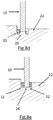
- Fig. 8b the two components are pressed against one another in such a way that the annular wall 26 and the coil core tube end surface lie on one another and then heated until the plastic material begins to flow ( Fig. 8d ) and finally liquefied ( Fig. 8e ) and flange wall 26 and plastic pipe 10 are materially welded to form solidified material flow / weld bead in the channels 32 of the annular recess 25.
- the weld bead is substantially flush with the flange surface and does not interfere in the winding space. This makes it possible to produce smooth and trouble-free windings up to the flange surface.
- the cohesive connection creates a high-tensile and resilient connection of the flanges on the spool core.
Landscapes
- Engineering & Computer Science (AREA)
- Mechanical Engineering (AREA)
- Physics & Mathematics (AREA)
- Electromagnetism (AREA)
- Health & Medical Sciences (AREA)
- Toxicology (AREA)
- Chemical & Material Sciences (AREA)
- Combustion & Propulsion (AREA)
- Storage Of Web-Like Or Filamentary Materials (AREA)
- Optics & Photonics (AREA)
Abstract
Description
- Die Erfindung betrifft eine Spule aus thermoplastischem Material zum Aufwickeln von Wickelgut sowie Verfahren zu ihrer Herstellung.
- Aus mehreren Ausgangsteilen hergestellte Spulen mit hohlem Kern sind in vielen Ausführungsformen bekannt. Sie werden zum Aufwickeln und zum Transport von Wickelgut, z. B. Kabeln, Drähten, Fäden, Seilen oder Kunststoffbändern, verwendet. Derartige Spulen bestehen meist aus einem ein- oder mehrteiligen zylindrischen oder konischem Spulenkern und zwei Flanschscheiben an dessen beiden Enden. Die Spulen können auf verschiedene Art und Weise zusammengebaut sein.
- Zum Stand der Technik wird auf die
DE 197 00 185 A1 und dieDE 40 01 250 A1 bezug genommen. - Die
DE 197 00 185 A1 beschreibt eine Spule, deren Spulenkern von den beiden endseitigen Flanschscheiben beiderseits zur Mitte konisch zusammenläuft und in der Mitte geteilt ist, so dass die beiden Spulenteile im Falle des Leertransports platzsparend gestapelt werden können. Die Verbindung der beiden Spulenteile erfolgt mit Hilfe einer Art von Bajonettverschluss, der eine Verbindung der beiden Teile mit einer gewissen Vorspannung ermöglicht. Die Vorspannung verhindert, dass die beiden Spulenteile sich ohne weiteres zurückdrehen und trennen können, jedoch ist dieses Zurückdrehen nicht zwingend ausgeschlossen, wenn die Spule einer rauhen Behandlung ausgesetzt ist oder, etwa beim Transport, für längere Zeit Schwingungen unterworfen wird. - Aus dem
DE 20 2013 101 355 U ist eine teilbare Spule zum Aufwickeln von strangförmigem Wickelgut bekannt geworden, bei der die Einzelbestandteile durch ein Stecksystem miteinander verbunden werden. - Aus der
US 6036138 A ist eine gelötete Metallspule für optische Fasern bzw. Lichtwellenleiter bekannt geworden, welche einen Spulenkern mittels Lot in einer Vertiefung eines Flansches befestigt. Dazu wird Löten eingesetzt. Löten ist ein thermisches Verfahren zum Fügen von Werkstoffen, wobei eine flüssige Phase durch Schmelzen eines Lotes (Schmelzlöten) oder durch Diffusion an den Grenzflächen (Diffusionslöten) entsteht. Dabei wird eine Legierung erzeugt, das Werkstück in der Tiefe aber nicht aufgeschmolzen: Die Liquidustemperatur der Grundwerkstoffe wird nicht erreicht. Nach dem Erstarren des Lotes ist eine stoffschlüssige Verbindung aus mindestens zwei Materialien - dem Lot und dem Werkstück - hergestellt. Es wird dort vorgeschlagen, dass die Lötstelle sich in einer ringförmigen Vertiefung des Flansches nahe der Durchgangs-Zentralbohrung bildet, so daß das Lot darin verläuft, während der Spulenkern gerichtet auf einer Stufe in der Vertiefung ruht. Dadurch wird eine stoffschlüssige Verbindung, bei welcher verflüssigtes Material in einem Ringkanal 32 aufgenommen wird, gebildet. Verlöten ist aber insofern ungünstig, als es störanfällig ist, so dass keine sichere stoffschlüssige Verbindung zwischen Spulenkern und Spulenflansch erfolgt. Die stoffschlüssige Verbindung erfolgt über das Lotmaterial. Löten hat stets das Problem, dass möglicherweise im Lot Fehlstellen auftreten oder das Lot mit den zu verbindenden Materialien nur unzureichend bindet oder in diese eindiffundiert. Schließlich muss es zusätzlich zu den Materialien der Spulenbestandteile vorgehalten und lokal appliziert werden, was zusätzlichen Aufwand erfordert. - Die bekannten Spulen mit hohlem Kern sind somit verbesserungsfähig, da die Verbindungen zwischen den Ringflanschen und dem Kern erhöhten Beanspruchungen häufig nicht widerstehen konnten und aufwändige Verfahren zu ihrer Herstellung benötigt wurden.
- Der Erfindung liegt daher die Aufgabe zugrunde, eine Spule der eingangs genannten Art zu schaffen, die einfacher, bevorzugt auch automatisch - herstellbar ist und eine hohe Sicherheit gegen unbeabsichtigte Auflösung der Spule in ihre Einzelkomponenten bietet.
- Die Aufgabe wird durch eine Spule nach Anspruch 1 sowie ein Verfahren nach Anspruch 8 gelöst. Vorteilhafte Weiterbildungen ergeben sich aus den abhängigen Ansprüchen.
- Erfindungsgemäß wird eine Spule zum Aufwickeln von strangförmigem Gut (Wickelgut), mit Flanschscheiben mit einer Flanschaußenfläche und einer Flanschinnenfläche mit einer zentralen Durchgangs-Zentralbohrung, die von einer ringförmigen Vertiefung mit einer darin verlaufenden Ringwand in der Flanschinnenfläche umgeben ist, und einem rohrförmigen Spulenkern, geschaffen, wobei der Spulenkern aus einem Rohr besteht, dessen Stirnflächen in den ringförmigen Vertiefungen der Flanschscheiben stoffschlüssig verbunden sind.
- Dadurch, dass die Spule aus nur drei Einzelteilen, von denen zwei identisch sind, aufgebaut wird, ist es möglich, verschiedenste Abmessungen - d.h. unterschiedliche Spulenkerndurchmesser und verschiedene Wickelbreiten mit nur zwei Grundteilen - verschiedenen Ringflanschen sowie Spulenkernrohren - zu verwirklichen.
- Durch Auswahl von Spulenkernrohren - bspw. Kunststoffrohren - unterschiedlicher Längen und Weiten können verschiedenste Wickelbreiten realisiert werden. Falls eine erhöhte Biegefestigkeit der Spulenkerne erwünscht ist, können Rohre mit Verstärkungsrippen eingesetzt werden. Genauso können Rohre mit eingeformten Stäben oder Filamenten verwendet werden.
- Die Anschlüsse für die Kunststoffrohre, hier eine umlaufende Ringwand/ringförmige Erhebung in einer ringförmigen Vertiefung der Flanschscheiben können -je nach Anforderung - mit unterschiedlichen Flanschdimensionen und Rohrflanschdurchmessern realisiert werden. Es ist dabei unwesentlich, ob der Flansch eine durchgehend konstante Stärke aufweist oder aus Gründen der Handhabung in Wickelautomaten und beim Transport im Bereich der Durchgangs-Zentralbohrung eine andere Stärke als in anderen Bereichen des Flansches aufweist.
- Bevorzugt erfolgt die Anbindung der Stirnflächen des Spulenkern-Rohrs an die Ringwand der Flanschinnenflächen durch Fügeverfahren, bei denen die Liquidustemperatur des Spulenmaterials überschritten wird - wie Schweißen, insbesondere Laserstrahlschweißen und konventionellen Fügeverfahren, wie Ultraschall-, Vibrations- oder Heißspiegelschweißen, Reibschweißen, Heizelementschweißen, Heißluftschweißen, Kontakt-Kunststoff schweißen, Infrarotschweißen. Dadurch wird kein zusätzliches Verbindungsmaterial für die stoffschlüssige Anbindung benötigt, es entsteht kein Abfall und die fertigen Spulen lassen sich leicht recyceln, da sie nur aus einem Material aufgebaut sind.
- Es ist aber auch möglich, die Stirnfläche des Spulenkerns in der Vertiefung der Flanschinnenfläche bzw. auf der umlaufenden Ringwand durch Lösemittelkleben anzukleben.
- Bspw. kann die ringförmige Vertiefung einen darin ausgebildeten Innen - und einen Außenkanal sowie eine die Kanäle für geschmolzenes Material trennende Ringwand aufweisen, die darin mit einer Spulenkernstirnfläche verbunden ist. In der ringförmigen Vertiefung im Flansch verläuft bei einer Ausführungsform in etwa mittig eine Ringwand, wobei beidseitig von dieser ein Innen- und Außenkanal für den beim Verbinden anfallende Materialüberschuß (Schmelzfluß, wie Schweißraupen oder Überschuß an beim Kleben verflüssigtem Material) ausgebildet ist.
- Bei einer typischen Ausführungsform der Erfindung als Kunststoffspule ist der Spulenkern ein extrudiertes Kunststoffrohr. Dies ist günstig, denn derartige Rohre sind leicht zu beschaffen und auf die gewünschte Wickelbreite mit einfachen Mitteln zu trennen, so dass sie ggf. auch an verschiedenen Montageorten beschaffbar sind und dort an geeignete Flanschscheiben angebracht werden können. So können Transportkosten für die Rohre eingespart werden
- Die Außenflächen der Flanschscheiben können im Bereich der Zentralbohrung Mitnehmer-Rastausnehmungen aufweisen, in die Mitnehmer einer Spulenantriebs- oder Spulenbremseinrichtung eingreifen können.
- Bevorzugt hat das Kunststoffrohr in etwa gleichen Durchmesser wie die Ringwand in der Flanschinnenfläche.
- Typische Spulen haben ein Kernrohr 10, das 150 - 700 mm lang ist
Die Kerndurchmesser betragen dann 110 bis 500 mm. - Die Zentralöffnung, in die Wickelwerkzeuge eingreifen können, kann bei diesen Ausführungsformen dann einen Durchmesser zwischen 55 und 130 mm haben
- Es ist auch möglich, dass die Anbindung des Spulenkerns in der Vertiefung der Flanschinnenfläche bspw. an der umlaufenden Erhebung auf der Vertiefung der Flanschinnenfläche durch Klebeverfahren erfolgt - dies ist insbesondere bei verschiedenen thermoplastischen oder leicht anlösbaren Kunststoffen möglich.
- Bevorzugt weist das Kunststoffrohr des Spulenkerns in etwa gleichen Durchmesser und Wanddicke wie die Ringwand in der Flanschvertiefung auf und ist an diese Erhebung stoffschlüssig angebunden. Ggf. anfallende Schweißraupen oder verflüssigtes Material läuft in den Außen- und Innenkanal der ringförmigen Vertiefung und unterstützt dort die Anbindung des Kunststoffrohrs des Spulenkerns. Die Spulen können Kerne haben, die 150 - 700 mm lang sind. Häufig ist der Kerndurchmesser in diesen Fällen zwischen 110 bis 500 mm. Die Zentralbohrung hat dann häufig einen Durchmesser zwischen 55 und 130 mm.
- Ein Verfahren zur Herstellung einer erfindungsgemäßen Kunststoffspule zum Aufwickeln von strangförmigem Gut weist die Schritte auf:
- a)Vorlegen von:
- zwei Flanschscheiben mit einer Flanschaußenfläche und einer Flanschinnenfläche und einer zentralen Durchgangs-Zentralbohrung, die von einer ringförmigen Vertiefung in der Flanschinnenfläche umgeben ist, und einer Ringwand in der ringförmigen Vertiefung, wobei mindestens ein Kanal in der ringförmigen Vertiefung neben der Ringwand zur Aufnahme von verflüssigtem Verbindungsmaterial verläuft; und
- einem Spulenkern etwa gleichen Durchmessers und Wanddicke wie die Ringwand;
- b)Aufeinanderdrücken von Spulenkernrohr und Ringwand; und
- c) Verflüssigen des Materials im Kontaktbereich zwischen Spulenkernrohr und Ringwand unter Fließen von verflüssigtem Material in den mindestens einen Kanal unter stoffschlüssigem Verbinden von Ringwand und Spulenkernrohrstirnfläche.
- Das Verflüssigen des Spulenmaterials kann durch Schweißverfahren, aber auch durch Lösemittelklebeverfahren erfolgen.
- Das Verfahren kann mit Metall oder Kunststoffen durchgeführt werden.
- Dadurch, dass ein Modulsystem für den Spulenaufbau entwickelt wurde, können mit wenigen Flanschscheiben und üblichen Rohrabschnitten die unterschiedlichsten Spulen materialsparend zur Verfügung gestellt werden.
- Somit erzielt die Erfindung unter anderem die Vorteile:
- Aufbau mit einfach verfügbaren Mitteln
- Ausgereifte Verbindungsverfahren
- die Verbindungsverfahren sind seit mehr als zehn Jahren zuverlässig im Einsatz.
- Es kann Recycling-Kunststoff oder Metall eingesetzt werden
- durch den vollständigen Stoffschluß zwischen den Flansch- und Kernmaterialien ohne Lot/Kleber wird geringes Gewicht bei hoher Stabilität erzielt und die Spule lässt sich leicht recyclen, da sie nur aus wenigen, bevorzugt einem Material, besteht.
- Modulsystem, mit dem verschiedene Spulengeometrien (Wickelbreite, Flanschdurchmesser) realisiert werden können
- Im folgendem werden bevorzugte Ausführungsbeispiele der Erfindung, auf die sie keinesfalls eingeschränkt ist, anhand der beigefügten Zeichnung näher erläutert. Darin zeigen:
-
Fig. 1 eine perspektivische Explosionsansicht von Einzelkomponenten einer Spule; -
Fig. 2 eine perspektivische Ansicht einer fertig zusammengebauten Spule -
Fig. 2A ein Detail derFigur 2 mit einer Zentrierkerbe und Wickelgut-Durchführungsöffnungen -
Fig. 3 ein Detail der Flanschinnenfläche mit Spulenkernrohr vor dem Verbinden mit einer Ringwand auf der ringförmigen Vertiefung und einem Außenkanal -
Fig. 3A ein Detail einer weiteren Ausführungsform der Flanschinnenfläche mit Spulenkernrohr vor dem Verbinden mit einer Ringwand auf der ringförmigen Vertiefung und einem Außen- und einem Innenkanal. -
Fig. 4 das Detail derFig. 3 und3A nach Verschweißen von Flansch und Kern -
Fig.5 eine Eingangsöffnung für Wickelgut im Spulenkernrohr für vollautomatische Wickelanlagen -
Fig. 6 schematisch die Ausgangsprodukte einer Spule im Längsschnitt; -
Fig. 7 schematisch die fertige Spule im Längsschnitt; und -
Fig. 8a - 8e ein Verfahren zur Herstellung einer erfindungsgemäßen Kunststoffspule - Die Erfindung wird nachfolgend am Beispiel einer Kunststoffspule näher erläutert - sie kann aber mit jeglichem thermoplastischen Material verwirklicht werden.
- In
Fig. 1 sind Einzelteile einer erfindungsgemäßen Kunststoffspule mit einem zylindrischen Spulenkern 10, an dessen Ende eine Flanschscheibe 22 angeordnet ist, perspektivisch gezeigt. Es ist erkennbar, dass der Spulenkern 10 ein Rohr ist. Schematisch ist dies inFig. 6 dargestellt. Die Flanschscheibe 22 weist eine Zentralbohrung 30 und eine ringförmige Vertiefung 25 auf der Flanschinnenseite auf, welche einen im wesentlichen dem Spulenkern-Rohr entsprechenden Durchmesser hat - In
Fig. 2 ist eine Ausführungsform einer vollständig aufgebauten erfindungsgemäßen Spule gezeigt. In den Flanschscheiben 22, 23 können Wickelgutdurchführungsöffnungen 33 - wie im Detail derFig. 2A gezeigt - ausgebildet sein, sowie ggf. eine Zentrierkerbe 27. - Wie in
Fig. 3 schematisch im Detail dargestellt, ist die Flanschscheibe 22 mit einer Ringwand 26 in der ringförmigen Vertiefung 25 so zum Spulenkern 10 angeordnet, dass die Spulenkernstirnfläche auf der Ringwand 26 in der ringförmigen Vertiefung 25 aufliegt. Außen neben der Ringwand 26 ist bei dieser Ausführungsform ein Kanal 32 ausgebildet, in den beim Schweißen/Kleben anfallendes überschüssiges Material, wie Schweißraupen, hineinläuft. Bei der Ausführungsform derFig. 3A sind neben der Ringwand 26 innen und außen Kanäle 32 für den gleichen Zweck ausgebildet. Die Ringwand 26 wird, wie inFig.4 im Detail gezeigt, bei dieser Ausführungsform mit den Spulenkernstirnflächen verschweißt, wie es auch durch die gewellten Linien inFig.7 angedeutet ist. Hier erfolgte das Verschweißen durch Heizelementschweißung - ein sehr zuverlässiges und übliches Verfahren. Das dabei als Schweißraupe austretende Kunststoffmaterial wird in dem mindestens einen Kanal 32 in der ringförmigen Vertiefung 25 im Flansch 22 neben der Ringwand 26 aufgenommen. Dadurch werden die Spulen-Funktion beeinträchtigende Schweißraupen auf dem Spulenkern 10 vermieden. Eine Eingangsöffnung 31 für Wickelgut (s.Fig. 5 ), bspw. für Kabel, in welcher der Anfang des Stranges festgelegt wird, wird so nicht zugesetzt oder unkontrolliert verengt, sondern bleibt auch nach dem Verschweißen/Verkleben barrierefrei durchgängig. - Die Spulenbestandteile 22, 24, 10 können insgesamt aus Kunststoff hergestellt werden. In diesem Fall kann beispielsweise die Ringwand 26 für den Spulenkern 10 unmittelbar an die Flanschscheiben 22, 24 angeformt sein, bspw. durch Spritzguss.
- Die rohrförmigen Spulenkerne 10 können durch Abtrennen von Abschnitten herkömmlicher Kunststoffrohre in der gewünschten Länge hergestellt werden und dann an ihren Stirnflächen mit den Ringwänden 26 verbunden - bevorzugt verschweißt -werden.
- Der Spulenkern 10, der den Wickelkern für das Wickelgut bildet, kann Durchbrechungen aufweisen, durch die das Wickelgut von der Innenseite des Spulenkerns behandelt werden kann. So kann beispielsweise über Durchbrechungen erwärmte Luft zur Trocknung des Wickelgutes hindurchgeführt werden. In Betracht kommt auch eine Behandlung mithilfe von Gasen oder Flüssigkeiten.
- Ebenso können die Flansche 22, 24 zur Gewichtsreduktion und Materialersparnis mit Durchbrüchen und dünneren Abschnitten ausgebildet werden, wie aus
Fig. 2 ersichtlich. Dort ist perspektivisch eine fertige Kunststoffspule gezeigt, wobei man deutlich Verstärkungsrippen und -Schlitze in den Flanschen zwecks Gewichts- und Materialersparnis erkennt. - Derartige Spulen können auch aus Metall aufgebaut werden, falls die Einsatzbedingungen dies erfordern. Die Verfahrensschritte sind dann, wie dem Fachmann geläufig, entsprechend auszuwählen und anzupassen.
- Ein Verfahren zur Herstellung einer verschweißten Kunststoffspule ist in
Fig. 8a bis 8e schematisch gezeigt. InFig. 8a ist perspektivisch und im Längsschnitt schematisch das Kunststoffrohr für den Spulenkern 10 und ein Flansch 22 mit ringförmiger Vertiefung 25 und einer darin verlaufenden Ringwand 26 gezeigt. InFig. 8b werden die beiden Bauteile gerichtet so aufeinandergedrückt, dass die Ringwand 26 und die Spulenkernrohrstirnfläche aufeinanderliegen und anschließend erwärmt, bis das Kunststoffmaterial zu fließen beginnt (Fig. 8d ) und sich schließlich verflüssigt (Fig. 8e ) und Flanschwand 26 und Kunststoffrohr 10 sich stoffschlüssig unter Ausbildung von erstarrtem Materialfluß/ Schweißraupe in den Kanälen 32 der ringförmigen Vertiefung 25 verschweißen. Durch die ringförmige Vertiefung 25 ist die Schweißraupe im wesentlichen bündig mit der Flanschoberfläche und stört im Wickelraum nicht. Dadurch ist es möglich, glatte und störungsfreie Wicklungen bis an die Flanschoberfläche herzustellen. Durch die stoffschlüssige Verbindung entsteht ein hoch-zugfester und belastbarer Anschluß der Flansche am Spulenkern. - Obwohl die Erfindung anhand von Ausführungsbeispielen mit Kunststoffteilen näher erläutert wurde, sind dem Fachmann viele Abwandlungen derselben aufgrund seines Fachwissens geläufig. Die Beschreibung der Erfindung ist daher lediglich exemplarisch und dem Fachmann geläufige Variationen fallen ebenfalls unter den Schutzumfang der Erfindung, wie er durch die Ansprüche definiert ist.
-
- 10
- Spulenkern
- 22
- Flanschscheibe
- 24
- Flanschscheibe
- 21
- Flanschinnenfläche
- 23
- Flanschinnenfläche
- 25
- ringförmige Vertiefung im Flansch um 30
- 26
- umlaufende Ringwand in 25
- 27
- Zentrierkerbe
- 30
- Durchgangs-Zentralbohrung
- 31
- Eingangsöffnung für Wickelgut
- 32
- Kanal
- 33
- Wickelgutdurchführungsöffnung
Claims (9)
- Spule zum Aufwickeln von strangförmigem Gut, mit
Flanschscheiben (22, 24) mit einer Flanschaußenfläche und einer Flanschinnenfläche (21, 23) mit jeweils einer zentralen Durchgangs-Zentralbohrung (30), die von einer ringförmigen Vertiefung (25) mit einer darin befindlichen Ringwand (26) in der Flanschinnenfläche umgeben ist, und
einem rohrförmigen Spulenkern (10),
wobei der Spulenkern (10) aus einem Rohr besteht, dessen Stirnflächen mit einer Ringwand (26) in den ringförmigen Vertiefungen (25) der Flanschscheiben (22, 24) stoffschlüssig verbunden sind,
wobei neben der Ringwand (26) mindestens ein Kanal in der ringförmigen Vertiefung (25) zur Aufnahme von verflüssigtem Verbindungsmaterial vorgesehen ist und der Spulenkern (10) in etwa gleichen Durchmesser wie die Ringwand (26) in der ringförmigen Vertiefung (25) hat. - Spule nach Anspruch 1, dadurch gekennzeichnet, dass die stoffschlüssige Anbindung des Spulenkerns (10) an der Ringwand (26) der Flanschinnenflächen (21, 23) durch Schweißen, insbesondere Heissluftschweißen, Kontaktschweißen, Ultraschallschweißen, Infrarotschweissen, Rohrspiegelschweißen, Heizelementschweißen, Kleben erfolgt ist.
- Spule nach Anspruch 1, dadurch gekennzeichnet, dass der Spulenkern (10) ein extrudiertes Kunststoffrohr ist.
- Spule nach einem der vorangehenden Ansprüche dadurch gekennzeichnet, dass der Spulenkern (10) 150 - 700 mm lang ist.
- Spule nach einem der vorangehenden Ansprüche, dadurch gekennzeichnet, dass der Durchmesser des Spulenkerns (10) 110 bis 500 mm beträgt.
- Spule nach einem der vorangehenden Ansprüche, dadurch gekennzeichnet, dass die Zentralöffnung (30) der Flanschscheiben (22,24) einen Durchmesser zwischen 55 und 130 mm hat
- Verfahren zur Herstellung einer gebauten Spule zum Aufwickeln von strangförmigem Gut aus thermoplastischem Material nach einem der vorangehenden Ansprüche, gekennzeichnet durch:a) Vorlegen von
zwei Flanschscheiben mit einer Flanschaußenfläche und einer Flanschinnenfläche mit jeweils einer zentralen Durchgangs-Zentralbohrung, die von einer ringförmigen Vertiefung in der Flanschinnenfläche umgeben ist, wobei in der ringförmigen Vertiefung eine Ringwand unter Ausbildung mindestens eines Kanals in der ringförmigen Vertiefung neben der Ringwand verläuft, und
einem Spulenkern etwa gleichen Durchmessers wie die Ringwand;b) Drücken des Spulenkerns auf die Ringwand in der ringförmigen Vertiefung der Flanschinnenfläche; undc) Verflüssigen des Materials im Kontaktbereich zwischen Spulenkernrohr und ringförmiger Erhebung unter Fließen von verflüssigtem Material in den mindestens einen Kanal und Ausbildung einer stoffschlüssigen Verbindung zwischen der Ringwand und dem Spulenkern. - Verfahren nach Anspruch 7, dadurch gekennzeichnet, dass das temporäre Verflüssigen des Materials im Kontaktbereich durch Schweißen oder Lösemittel durchgeführt wird.
- Verfahren nach einem der Ansprüche 7 oder 8, dadurch gekennzeichnet, dass die Spule aus Metall oder Kunststoff hergestellt wird.
Priority Applications (3)
| Application Number | Priority Date | Filing Date | Title |
|---|---|---|---|
| CA2993722A CA2993722A1 (en) | 2017-07-14 | 2018-01-31 | Spool and method for its manufacture |
| MX2018001944A MX2018001944A (es) | 2017-07-14 | 2018-02-15 | Bobina y metodo para su produccion. |
| US15/903,099 US10919728B2 (en) | 2017-07-14 | 2018-02-23 | Spool made of a thermoplastic material for the winding of winding material, as well as to a method for manufacturing the same |
Applications Claiming Priority (1)
| Application Number | Priority Date | Filing Date | Title |
|---|---|---|---|
| DE202017104227.8U DE202017104227U1 (de) | 2017-07-14 | 2017-07-14 | Spule zum Aufwickeln von Wickelgut |
Publications (3)
| Publication Number | Publication Date |
|---|---|
| EP3428097A1 true EP3428097A1 (de) | 2019-01-16 |
| EP3428097C0 EP3428097C0 (de) | 2024-07-17 |
| EP3428097B1 EP3428097B1 (de) | 2024-07-17 |
Family
ID=59701101
Family Applications (1)
| Application Number | Title | Priority Date | Filing Date |
|---|---|---|---|
| EP17209031.8A Active EP3428097B1 (de) | 2017-07-14 | 2017-12-20 | Spule aus thermoplastischem material und verfahren zu ihrer herstellung |
Country Status (6)
| Country | Link |
|---|---|
| US (1) | US10919728B2 (de) |
| EP (1) | EP3428097B1 (de) |
| CA (1) | CA2993722A1 (de) |
| DE (1) | DE202017104227U1 (de) |
| MX (1) | MX2018001944A (de) |
| PL (1) | PL3428097T3 (de) |
Families Citing this family (3)
| Publication number | Priority date | Publication date | Assignee | Title |
|---|---|---|---|---|
| MY202618A (en) * | 2015-08-10 | 2024-05-10 | Dexerials Corp | Reel member, film housing body, and method for manufacturing reel member |
| CN114508621A (zh) * | 2022-01-26 | 2022-05-17 | 广东威灵电机制造有限公司 | 阀体组件和电子膨胀阀 |
| CN121368565A (zh) * | 2023-05-23 | 2026-01-20 | 凡得公司 | 感应粘接卷筒 |
Citations (7)
| Publication number | Priority date | Publication date | Assignee | Title |
|---|---|---|---|---|
| US3501110A (en) * | 1967-01-24 | 1970-03-17 | Nicholson File Co | Plastic spool and method of making same |
| GB2020629A (en) * | 1978-05-08 | 1979-11-21 | Minnesota Mining & Mfg | Tape reels |
| WO1992020603A1 (de) * | 1991-05-17 | 1992-11-26 | Hildebrandt-Spulen-Bobbins Gmbh | Spulenkörper für fadenförmiges wickelgut und herstellungsverfahren hierzu |
| JPH1125643A (ja) * | 1997-07-02 | 1999-01-29 | Fuji Photo Film Co Ltd | 磁気テープカートリッジ用リールの溶着方法 |
| US6036138A (en) * | 1998-05-06 | 2000-03-14 | Mckechnie Plastic Components, Inc. | Spool for holding windings of optical fiber |
| JP2004202828A (ja) * | 2002-12-25 | 2004-07-22 | Sony Corp | 超音波溶着ホーン、超音波溶着装置及びテープリールの製造方法 |
| US20050284559A1 (en) * | 2004-06-17 | 2005-12-29 | Ripplinger Jacob F | Cross-grade spin welding apparatus and method |
Family Cites Families (4)
| Publication number | Priority date | Publication date | Assignee | Title |
|---|---|---|---|---|
| DE4001250A1 (de) | 1990-01-18 | 1991-07-25 | Industriebedarf Eisele & Co Gm | Spule |
| DE19700185B4 (de) | 1997-01-04 | 2005-06-23 | SCHÜCO International KG | Spule zur Aufnahme von wickelbarem Strangmaterial |
| DE20021819U1 (de) * | 2000-12-22 | 2001-03-29 | Vogt, Herbert, 30938 Burgwedel | Spule zum Aufwickeln von Kabeln o.dgl. |
| DE202013101355U1 (de) | 2013-03-28 | 2013-04-12 | Häfner & Krullmann Gmbh | Teilbare Spule |
-
2017
- 2017-07-14 DE DE202017104227.8U patent/DE202017104227U1/de active Active
- 2017-12-20 EP EP17209031.8A patent/EP3428097B1/de active Active
- 2017-12-20 PL PL17209031.8T patent/PL3428097T3/pl unknown
-
2018
- 2018-01-31 CA CA2993722A patent/CA2993722A1/en active Pending
- 2018-02-15 MX MX2018001944A patent/MX2018001944A/es unknown
- 2018-02-23 US US15/903,099 patent/US10919728B2/en active Active
Patent Citations (7)
| Publication number | Priority date | Publication date | Assignee | Title |
|---|---|---|---|---|
| US3501110A (en) * | 1967-01-24 | 1970-03-17 | Nicholson File Co | Plastic spool and method of making same |
| GB2020629A (en) * | 1978-05-08 | 1979-11-21 | Minnesota Mining & Mfg | Tape reels |
| WO1992020603A1 (de) * | 1991-05-17 | 1992-11-26 | Hildebrandt-Spulen-Bobbins Gmbh | Spulenkörper für fadenförmiges wickelgut und herstellungsverfahren hierzu |
| JPH1125643A (ja) * | 1997-07-02 | 1999-01-29 | Fuji Photo Film Co Ltd | 磁気テープカートリッジ用リールの溶着方法 |
| US6036138A (en) * | 1998-05-06 | 2000-03-14 | Mckechnie Plastic Components, Inc. | Spool for holding windings of optical fiber |
| JP2004202828A (ja) * | 2002-12-25 | 2004-07-22 | Sony Corp | 超音波溶着ホーン、超音波溶着装置及びテープリールの製造方法 |
| US20050284559A1 (en) * | 2004-06-17 | 2005-12-29 | Ripplinger Jacob F | Cross-grade spin welding apparatus and method |
Also Published As
| Publication number | Publication date |
|---|---|
| CA2993722A1 (en) | 2019-01-14 |
| US20190016555A1 (en) | 2019-01-17 |
| EP3428097C0 (de) | 2024-07-17 |
| US10919728B2 (en) | 2021-02-16 |
| EP3428097B1 (de) | 2024-07-17 |
| DE202017104227U1 (de) | 2017-08-04 |
| PL3428097T3 (pl) | 2024-11-25 |
| MX2018001944A (es) | 2019-02-08 |
Similar Documents
| Publication | Publication Date | Title |
|---|---|---|
| EP0689931B1 (de) | Verfahren zum Schweissen von Kunststoffrohren und Muffe zur Durchführung des Verfahrens | |
| EP0531750B1 (de) | Verfahren zum Verschweissen von aus thermoplastischem Kunststoff bestehenden Rohren | |
| EP1815904B1 (de) | Mischelement für einen statischen Mischer, statischer Mischer sowie Verfahren zum Herstellen eines dergestalten Mischelements | |
| DE1908888A1 (de) | Rohrverbindung und Verfahren zu ihrer Herstellung | |
| DE4142047A1 (de) | Verfahren zum umhuellen mindestens eines lichtwellenleiters mit einer schutzschicht und zum anbringen von verstaerkungselementen | |
| EP2059366A1 (de) | Verfahren zum schweissen von bauteilen mit geschlossenem hohlquerschnitt mit einem zwischen den beiden überlappenden bauteilen erzeugten umlaufenden spalt | |
| EP2159037A1 (de) | Verbindungs- oder Abzweigelement zum Verbinden mit einem Rohrendabschnitt im Laserdurchstrahlverfahren sowie Laserkopf und Verfahren zum Verbinden | |
| WO2001036173A1 (de) | Spritzgiessvorrichtung zur umspritzung von rundschweissnähten einer rohrleitung | |
| EP3428097B1 (de) | Spule aus thermoplastischem material und verfahren zu ihrer herstellung | |
| EP0240732B1 (de) | Schweisselement zum Verschweissen stumpfgestossener Rohre aus Kunststoff | |
| EP0741628A1 (de) | Verfahren zur herstellung einer schweissverbindung und nach diesem verfahren hergestellter transport und lagerbehälter für abgebrannte kernbrennstoffkasseten | |
| DE112008001067B4 (de) | Verfahren zur Herstellung eines metallverstärkten Kunststoff-Verbundrohrs und metallverstärktes Kunststoff-Verbundrohr | |
| DE19736575C5 (de) | Kunstoffwalze, Verfahren zur Herstellung derselben und Vorrichtung zur Durchführung des Verfahrens | |
| DE69528936T2 (de) | Vorrichtung zum Verbinden von Metallmänteln optischer Kabel und Verfahren zum Verbinden oder Spleissen zweier optischer Kabel | |
| DE2708593A1 (de) | Zusammengesetztes rohr aus verschiedenen kunststoffen und verfahren zu dessen herstellung | |
| DE3922335C1 (de) | ||
| DE102012211651A1 (de) | Verfahren zur Herstellung eines Wickelrohrs | |
| DE19607595C2 (de) | Führungsdrahtkern, insbesondere für ein chirurgisches Instrument | |
| DE19719071A1 (de) | Sammeltank für Wasser sowie Verfahren zu dessen Herstellung | |
| DE3404294C1 (de) | Rohrteil aus einem thermoplastischen Kunststoff | |
| DE3230354A1 (de) | Fittings zum verbinden von rohren | |
| DE102008012024B3 (de) | Wickelform, Wickelrohr und Verfahren zu seiner Herstellung | |
| EP1188704A1 (de) | Kern für eine Spinnspule und Verfahren zur Herstellung des Kerns | |
| DE7406802U (de) | Kupplungsring zum Verbinden stumpf aneinanderstoßender Rohrenden | |
| EP2896575A1 (de) | Kombinationsfass aus zwei Kunststofffässern |
Legal Events
| Date | Code | Title | Description |
|---|---|---|---|
| PUAI | Public reference made under article 153(3) epc to a published international application that has entered the european phase |
Free format text: ORIGINAL CODE: 0009012 |
|
| STAA | Information on the status of an ep patent application or granted ep patent |
Free format text: STATUS: THE APPLICATION HAS BEEN PUBLISHED |
|
| AK | Designated contracting states |
Kind code of ref document: A1 Designated state(s): AL AT BE BG CH CY CZ DE DK EE ES FI FR GB GR HR HU IE IS IT LI LT LU LV MC MK MT NL NO PL PT RO RS SE SI SK SM TR |
|
| AX | Request for extension of the european patent |
Extension state: BA ME |
|
| STAA | Information on the status of an ep patent application or granted ep patent |
Free format text: STATUS: REQUEST FOR EXAMINATION WAS MADE |
|
| 17P | Request for examination filed |
Effective date: 20190712 |
|
| RBV | Designated contracting states (corrected) |
Designated state(s): AL AT BE BG CH CY CZ DE DK EE ES FI FR GB GR HR HU IE IS IT LI LT LU LV MC MK MT NL NO PL PT RO RS SE SI SK SM TR |
|
| STAA | Information on the status of an ep patent application or granted ep patent |
Free format text: STATUS: EXAMINATION IS IN PROGRESS |
|
| 17Q | First examination report despatched |
Effective date: 20200803 |
|
| RAP3 | Party data changed (applicant data changed or rights of an application transferred) |
Owner name: PURUS PLASTICS GMBH |
|
| GRAP | Despatch of communication of intention to grant a patent |
Free format text: ORIGINAL CODE: EPIDOSNIGR1 |
|
| STAA | Information on the status of an ep patent application or granted ep patent |
Free format text: STATUS: GRANT OF PATENT IS INTENDED |
|
| RIC1 | Information provided on ipc code assigned before grant |
Ipc: B29C 65/48 20060101ALI20240129BHEP Ipc: B29C 65/20 20060101ALI20240129BHEP Ipc: B29C 65/14 20060101ALI20240129BHEP Ipc: B29C 65/10 20060101ALI20240129BHEP Ipc: B29C 65/08 20060101ALI20240129BHEP Ipc: B29C 65/00 20060101ALI20240129BHEP Ipc: B23K 33/00 20060101ALI20240129BHEP Ipc: B65H 75/50 20060101ALI20240129BHEP Ipc: B65H 75/14 20060101AFI20240129BHEP |
|
| INTG | Intention to grant announced |
Effective date: 20240304 |
|
| GRAS | Grant fee paid |
Free format text: ORIGINAL CODE: EPIDOSNIGR3 |
|
| GRAA | (expected) grant |
Free format text: ORIGINAL CODE: 0009210 |
|
| STAA | Information on the status of an ep patent application or granted ep patent |
Free format text: STATUS: THE PATENT HAS BEEN GRANTED |
|
| AK | Designated contracting states |
Kind code of ref document: B1 Designated state(s): AL AT BE BG CH CY CZ DE DK EE ES FI FR GB GR HR HU IE IS IT LI LT LU LV MC MK MT NL NO PL PT RO RS SE SI SK SM TR |
|
| REG | Reference to a national code |
Ref country code: GB Ref legal event code: FG4D Free format text: NOT ENGLISH |
|
| REG | Reference to a national code |
Ref country code: CH Ref legal event code: EP |
|
| REG | Reference to a national code |
Ref country code: DE Ref legal event code: R096 Ref document number: 502017016258 Country of ref document: DE |
|
| REG | Reference to a national code |
Ref country code: IE Ref legal event code: FG4D Free format text: LANGUAGE OF EP DOCUMENT: GERMAN |
|
| U01 | Request for unitary effect filed |
Effective date: 20240801 |
|
| U07 | Unitary effect registered |
Designated state(s): AT BE BG DE DK EE FI FR IT LT LU LV MT NL PT SE SI Effective date: 20240813 |
|
| U20 | Renewal fee for the european patent with unitary effect paid |
Year of fee payment: 8 Effective date: 20241002 |
|
| PG25 | Lapsed in a contracting state [announced via postgrant information from national office to epo] |
Ref country code: NO Free format text: LAPSE BECAUSE OF FAILURE TO SUBMIT A TRANSLATION OF THE DESCRIPTION OR TO PAY THE FEE WITHIN THE PRESCRIBED TIME-LIMIT Effective date: 20241017 |
|
| PG25 | Lapsed in a contracting state [announced via postgrant information from national office to epo] |
Ref country code: GR Free format text: LAPSE BECAUSE OF FAILURE TO SUBMIT A TRANSLATION OF THE DESCRIPTION OR TO PAY THE FEE WITHIN THE PRESCRIBED TIME-LIMIT Effective date: 20241018 |
|
| PG25 | Lapsed in a contracting state [announced via postgrant information from national office to epo] |
Ref country code: IS Free format text: LAPSE BECAUSE OF FAILURE TO SUBMIT A TRANSLATION OF THE DESCRIPTION OR TO PAY THE FEE WITHIN THE PRESCRIBED TIME-LIMIT Effective date: 20241117 |
|
| PG25 | Lapsed in a contracting state [announced via postgrant information from national office to epo] |
Ref country code: HR Free format text: LAPSE BECAUSE OF FAILURE TO SUBMIT A TRANSLATION OF THE DESCRIPTION OR TO PAY THE FEE WITHIN THE PRESCRIBED TIME-LIMIT Effective date: 20240717 |
|
| PG25 | Lapsed in a contracting state [announced via postgrant information from national office to epo] |
Ref country code: ES Free format text: LAPSE BECAUSE OF FAILURE TO SUBMIT A TRANSLATION OF THE DESCRIPTION OR TO PAY THE FEE WITHIN THE PRESCRIBED TIME-LIMIT Effective date: 20240717 Ref country code: RS Free format text: LAPSE BECAUSE OF FAILURE TO SUBMIT A TRANSLATION OF THE DESCRIPTION OR TO PAY THE FEE WITHIN THE PRESCRIBED TIME-LIMIT Effective date: 20241017 |
|
| PG25 | Lapsed in a contracting state [announced via postgrant information from national office to epo] |
Ref country code: RS Free format text: LAPSE BECAUSE OF FAILURE TO SUBMIT A TRANSLATION OF THE DESCRIPTION OR TO PAY THE FEE WITHIN THE PRESCRIBED TIME-LIMIT Effective date: 20241017 Ref country code: NO Free format text: LAPSE BECAUSE OF FAILURE TO SUBMIT A TRANSLATION OF THE DESCRIPTION OR TO PAY THE FEE WITHIN THE PRESCRIBED TIME-LIMIT Effective date: 20241017 Ref country code: IS Free format text: LAPSE BECAUSE OF FAILURE TO SUBMIT A TRANSLATION OF THE DESCRIPTION OR TO PAY THE FEE WITHIN THE PRESCRIBED TIME-LIMIT Effective date: 20241117 Ref country code: HR Free format text: LAPSE BECAUSE OF FAILURE TO SUBMIT A TRANSLATION OF THE DESCRIPTION OR TO PAY THE FEE WITHIN THE PRESCRIBED TIME-LIMIT Effective date: 20240717 Ref country code: GR Free format text: LAPSE BECAUSE OF FAILURE TO SUBMIT A TRANSLATION OF THE DESCRIPTION OR TO PAY THE FEE WITHIN THE PRESCRIBED TIME-LIMIT Effective date: 20241018 Ref country code: ES Free format text: LAPSE BECAUSE OF FAILURE TO SUBMIT A TRANSLATION OF THE DESCRIPTION OR TO PAY THE FEE WITHIN THE PRESCRIBED TIME-LIMIT Effective date: 20240717 |
|
| PG25 | Lapsed in a contracting state [announced via postgrant information from national office to epo] |
Ref country code: SM Free format text: LAPSE BECAUSE OF FAILURE TO SUBMIT A TRANSLATION OF THE DESCRIPTION OR TO PAY THE FEE WITHIN THE PRESCRIBED TIME-LIMIT Effective date: 20240717 |
|
| PG25 | Lapsed in a contracting state [announced via postgrant information from national office to epo] |
Ref country code: CZ Free format text: LAPSE BECAUSE OF FAILURE TO SUBMIT A TRANSLATION OF THE DESCRIPTION OR TO PAY THE FEE WITHIN THE PRESCRIBED TIME-LIMIT Effective date: 20240717 |
|
| PG25 | Lapsed in a contracting state [announced via postgrant information from national office to epo] |
Ref country code: SK Free format text: LAPSE BECAUSE OF FAILURE TO SUBMIT A TRANSLATION OF THE DESCRIPTION OR TO PAY THE FEE WITHIN THE PRESCRIBED TIME-LIMIT Effective date: 20240717 |
|
| PLBE | No opposition filed within time limit |
Free format text: ORIGINAL CODE: 0009261 |
|
| STAA | Information on the status of an ep patent application or granted ep patent |
Free format text: STATUS: NO OPPOSITION FILED WITHIN TIME LIMIT |
|
| 26N | No opposition filed |
Effective date: 20250422 |
|
| PG25 | Lapsed in a contracting state [announced via postgrant information from national office to epo] |
Ref country code: MC Free format text: LAPSE BECAUSE OF FAILURE TO SUBMIT A TRANSLATION OF THE DESCRIPTION OR TO PAY THE FEE WITHIN THE PRESCRIBED TIME-LIMIT Effective date: 20240717 |
|
| REG | Reference to a national code |
Ref country code: CH Ref legal event code: PL |
|
| PG25 | Lapsed in a contracting state [announced via postgrant information from national office to epo] |
Ref country code: CH Free format text: LAPSE BECAUSE OF NON-PAYMENT OF DUE FEES Effective date: 20241231 |
|
| PG25 | Lapsed in a contracting state [announced via postgrant information from national office to epo] |
Ref country code: IE Free format text: LAPSE BECAUSE OF NON-PAYMENT OF DUE FEES Effective date: 20241220 |
|
| PG25 | Lapsed in a contracting state [announced via postgrant information from national office to epo] |
Ref country code: RO Free format text: LAPSE BECAUSE OF FAILURE TO SUBMIT A TRANSLATION OF THE DESCRIPTION OR TO PAY THE FEE WITHIN THE PRESCRIBED TIME-LIMIT Effective date: 20240717 |
|
| U20 | Renewal fee for the european patent with unitary effect paid |
Year of fee payment: 9 Effective date: 20251204 |
|
| PGFP | Annual fee paid to national office [announced via postgrant information from national office to epo] |
Ref country code: GB Payment date: 20251229 Year of fee payment: 9 |
|
| PGFP | Annual fee paid to national office [announced via postgrant information from national office to epo] |
Ref country code: PL Payment date: 20251126 Year of fee payment: 9 |