EP3428527A1 - Überhitzer- und nachbrennerdampftemperatursteuerung über einen abgasbypass - Google Patents
Überhitzer- und nachbrennerdampftemperatursteuerung über einen abgasbypass Download PDFInfo
- Publication number
- EP3428527A1 EP3428527A1 EP17181394.2A EP17181394A EP3428527A1 EP 3428527 A1 EP3428527 A1 EP 3428527A1 EP 17181394 A EP17181394 A EP 17181394A EP 3428527 A1 EP3428527 A1 EP 3428527A1
- Authority
- EP
- European Patent Office
- Prior art keywords
- superheater
- steam generator
- heat recovery
- recovery steam
- tube banks
- Prior art date
- Legal status (The legal status is an assumption and is not a legal conclusion. Google has not performed a legal analysis and makes no representation as to the accuracy of the status listed.)
- Withdrawn
Links
- 238000011084 recovery Methods 0.000 claims abstract description 45
- 238000000034 method Methods 0.000 claims abstract description 10
- 230000000903 blocking effect Effects 0.000 claims description 13
- 239000007789 gas Substances 0.000 description 29
- 238000013461 design Methods 0.000 description 5
- 230000015572 biosynthetic process Effects 0.000 description 3
- 238000005755 formation reaction Methods 0.000 description 3
- 238000010521 absorption reaction Methods 0.000 description 2
- 238000012986 modification Methods 0.000 description 2
- 230000004048 modification Effects 0.000 description 2
- 238000003303 reheating Methods 0.000 description 2
- 239000007921 spray Substances 0.000 description 2
- 230000008646 thermal stress Effects 0.000 description 2
- XLYOFNOQVPJJNP-UHFFFAOYSA-N water Substances O XLYOFNOQVPJJNP-UHFFFAOYSA-N 0.000 description 2
- 230000003247 decreasing effect Effects 0.000 description 1
- 230000001419 dependent effect Effects 0.000 description 1
- 238000011161 development Methods 0.000 description 1
- 230000018109 developmental process Effects 0.000 description 1
- 238000010438 heat treatment Methods 0.000 description 1
- 229920006395 saturated elastomer Polymers 0.000 description 1
- 238000012546 transfer Methods 0.000 description 1
Images



Classifications
-
- F—MECHANICAL ENGINEERING; LIGHTING; HEATING; WEAPONS; BLASTING
- F22—STEAM GENERATION
- F22G—SUPERHEATING OF STEAM
- F22G5/00—Controlling superheat temperature
- F22G5/04—Controlling superheat temperature by regulating flue gas flow, e.g. by proportioning or diverting
-
- F—MECHANICAL ENGINEERING; LIGHTING; HEATING; WEAPONS; BLASTING
- F22—STEAM GENERATION
- F22G—SUPERHEATING OF STEAM
- F22G7/00—Steam superheaters characterised by location, arrangement, or disposition
- F22G7/12—Steam superheaters characterised by location, arrangement, or disposition in flues
Definitions
- the present invention relates to a heat recovery steam generator and a method to control the steam outlet temperature of a heat recovery steam generator.
- the invention relates to a heat recovery steam generator, where the exhaust gas flow is partly bypassed around superheater and reheater tube banks or where some superheater or reheater tube banks are blocked. Furthermore, the invention relates to a corresponding method of bypassing exhaust gas flow or blocking tube banks.
- a typical disadvantage of such known combined cycle power plants is that as a result the steam absorbs more heat from the gas turbine exhaust gas resulting in increase of superheater and reheater steam outlet temperature above the design temperature.
- inter stage attemperators are usually used to control the superheater and reheater temperatures in a heat recovery steam generator when the steam temperature is more than the designed temperature. So spray of comparatively cold water in the inter stage superheater / reheater is done to reduce the steam temperature to the allowable level.
- a final attemperator improves the efficiency compared to the use of the interstage attemperator but is not accepted by many clients and discouraged by ASME (American Society of Mechanical Engineers).
- steam bypass is used to control the final outlet temperature.
- Saturated steam from the drum outlet is mixed with the steam before the last superheater to control the steam temperature at the outlet of the last superheater.
- a typical disadvantage of such known combined cycle power plants is that the design and availability of steam bypass control valve is difficult regarding size and characteristic as the available pressure drop over the bypass control valve is too low.
- a further goal of the invention is to provide a method to control the steam outlet temperature of a heat recovery steam generator.
- a heat recovery steam generator comprising superheater and reheater tube banks forming heat exchanger surfaces, further comprising a device for guiding exhaust gas around at least a part of the superheater and reheater tube banks.
- the essential idea of the present invention is that during the startup or part load operation, when there is less steam flow in the superheater and reheater section, the outlet steam temperature can be controlled by decreasing contact between the hot exhaust gases and the heat exchanger surfaces.
- the device is designed to guide at least a part of the exhaust gas around the superheater and reheater tube banks, i.e. bypassing (partly) the exhaust gas flow around the superheater and reheater tubes banks.
- this objective can be achieved by an embodiment, wherein the device is designed to guide the exhaust gas around at least a part of superheater and reheater tube banks, i.e. covering (partly) some superheater and reheater tube banks.
- the method to control the steam outlet temperature of a heat recovery steam generator comprising superheater and reheater tube banks forming heat exchanger surfaces according to the present invention is characterized by the step of guiding exhaust gas at least partly around the superheater and reheater tube banks.
- the efficiency of the heat recovery steam generator in the low / part load is improved as the final steam temperature is controlled with a higher efficiency (even higher than steam bypass).
- Figure 1 shows a heat recovery steam generator 1 comprising different heat exchanger surfaces 4 arranged one after another beginning at the hot end 6 of the heat recovery steam generator 1 with third high pressure superheater 7, followed by third reheater 8, second high pressure superheater 9, second reheater 10, first high pressure superheater 11, first reheater 12, second high pressure evaporator 13, first high pressure evaporator 14, high pressure economizier 15, some not otherwise specified intermediate pressure and low pressure heat exchanger surfaces 16, 17 and finally a condensate preheater 18 at the cold end 19 of the heat recovery steam generator 1.
- gas turbine exhaust gas 20 enters the heat recovery steam generator 1 at its hot end 6 and leaves it the cold end through the stack 21.
- the exhaust gas 20 is prevented from passing through the superheater and reheater section 22 in its entirety by providing a bypass channel 23 between the walls 24 of the heat recovery steam generator 1 and heat exchanger surfaces 4 of the superheater and reheater tube banks 2,3.
- Dampers 27 are to be provided in each of the bypass channels 23 so that the bypass flow of exhaust gas 20 can be controlled to maintain the superheater and reheater steam outlet temperature.
- the device 5 for guiding exhaust gas around at least a part of the superheater and reheater tube banks 2, 3 is a closed bypass channel 23 allowing for bypassing all superheater and reheater tube banks at once.
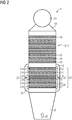
- Figure 2 indicates a similar concept as Figure 1 , but in this case an external bypass duct 25 outside the walls 24 of the heat recovery steam generator 1 is used, without changing the existing boiler structure design. This can also be used to retrofit in operating plants, if this new concept shall be implemented.
- the bypassed high temperature exhaust gas is mixed with the relatively less temperature exhaust gas 20 which passed through the superheater and reheater tube banks 2, 3 there are chances of temperature layer formation.
- the bypass channel 23 is a channel open to the superheater and reheater tube banks 2, 3, wherein dampers 27 are arranged in the bypass channel 23 between walls 24 of the heat recovery steam generator 1 and the tube banks 2, 3 for each superheater and reheater heat exchanger surfaces 4 allowing for bypassing selected heat exchanger surfaces 4.
- This embodiment indicates a more precise control of the exhaust gas bypass.
- the concept is similar to that of figure 1 , but with a damper 27 in each heater bypass channel 23 it can be selected which heat exchanger surface 4 to bypass and which one not to bypass, thus having a better and more flexible control to maintain the superheater and reheater outlet temperature.
- the exhaust gas 20 can be bypassed around third high pressure superheater 7 and third high pressure reheater 8 only as per requirement and not bypassing the rest of the entire superheating and reheating section 22.
- Figure 5 , figure 6 and figure 7 show options, which enable the proper mixing of the exhaust gas 20 and making a temperature homogenous exhaust gas after it is bypassed. Formation of temperature layers cannot be avoided completely by these measures, but could be reduced further by suitable mixing arrangements (like the use of perforated tubes).
- the embodiment of figure 5 shows several bypass channels 23 not necessarily arranged close to the walls 24 of the heat recovery steam generator 1.
- Figures 6 and 7 show embodiments where the bypass channel 23 comprises a staggered arrangement of bypass channel sections 28.
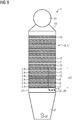
- Figure 8 and figure 9 show advantageous embodiments where the device 5 comprises blocking elements 29 adjustably blocking at least a part of the heat exchanger surfaces 4 formed by the tube banks 2, 3.
- the blocking elements 29 are arranged to block at least a heat exchanger surface 4 over its full height, so that the flow of the exhaust gas 20 can be restricted to flow through some part of the superheater and reheater tube banks 2, 3 by isolating the corresponding heat exchanger surfaces 4 vertically with the help of one or more sets of dampers 27. This will reduce the effective heat absorption surface area, leading to less heat absorption in the superheater and reheater tube banks 2, 3 and more heat is available for the evaporators, intermediate and low pressure sections, economizers, condensate preheaters 18, etc.
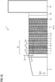
- Figure 10 is an option in which the heat exchanger surface 4 is isolated horizontally, i.e. where the blocking elements 29 are arranged to block a heat exchanger surface 4 over its entire width and over a part of its height, thus reducing all the superheater /reheater heat exchangers tube length & surface area equally, when tubes of the tube banks 2, 3 are vertically oriented.
- Figure 10 shows the damper 27 in its closed (down) and its open (up) position.
- This option has an advantage that all the steam tubes are equally heated and thus generates minimal thermal stress in the header, unlike in options shown in figure 8 and figure 9 wherein due to unequal heating of the heat transfer area there may be some additional thermal stress on the header, which needs to be taken care with suitable header design.
Landscapes
- Engineering & Computer Science (AREA)
- Mechanical Engineering (AREA)
- General Engineering & Computer Science (AREA)
- Heat-Exchange Devices With Radiators And Conduit Assemblies (AREA)
Priority Applications (1)
| Application Number | Priority Date | Filing Date | Title |
|---|---|---|---|
| EP17181394.2A EP3428527A1 (de) | 2017-07-14 | 2017-07-14 | Überhitzer- und nachbrennerdampftemperatursteuerung über einen abgasbypass |
Applications Claiming Priority (1)
| Application Number | Priority Date | Filing Date | Title |
|---|---|---|---|
| EP17181394.2A EP3428527A1 (de) | 2017-07-14 | 2017-07-14 | Überhitzer- und nachbrennerdampftemperatursteuerung über einen abgasbypass |
Publications (1)
| Publication Number | Publication Date |
|---|---|
| EP3428527A1 true EP3428527A1 (de) | 2019-01-16 |
Family
ID=59362969
Family Applications (1)
| Application Number | Title | Priority Date | Filing Date |
|---|---|---|---|
| EP17181394.2A Withdrawn EP3428527A1 (de) | 2017-07-14 | 2017-07-14 | Überhitzer- und nachbrennerdampftemperatursteuerung über einen abgasbypass |
Country Status (1)
| Country | Link |
|---|---|
| EP (1) | EP3428527A1 (de) |
Citations (6)
| Publication number | Priority date | Publication date | Assignee | Title |
|---|---|---|---|---|
| JPH0452401A (ja) * | 1990-06-20 | 1992-02-20 | Osaka Gas Co Ltd | 脱硝装置を備える排熱回収装置 |
| JPH0828808A (ja) * | 1994-07-19 | 1996-02-02 | Babcock Hitachi Kk | 廃熱回収ボイラ装置およびその制御方法 |
| EP0807785A1 (de) * | 1996-05-14 | 1997-11-19 | Ansaldo Energia S.P.A. | Abhitzekessel |
| US6125623A (en) * | 1998-03-03 | 2000-10-03 | Siemens Westinghouse Power Corporation | Heat exchanger for operating with a combustion turbine in either a simple cycle or a combined cycle |
| US20130098313A1 (en) * | 2011-10-21 | 2013-04-25 | General Electric Company | System and apparatus for controlling temperature in a heat recovery steam generator |
| US20170022847A1 (en) * | 2015-07-23 | 2017-01-26 | Mitsubishi Hitachi Power Systems, Ltd. | Combined Cycle Power Plant and Start-Up Method of the Same |
-
2017
- 2017-07-14 EP EP17181394.2A patent/EP3428527A1/de not_active Withdrawn
Patent Citations (6)
| Publication number | Priority date | Publication date | Assignee | Title |
|---|---|---|---|---|
| JPH0452401A (ja) * | 1990-06-20 | 1992-02-20 | Osaka Gas Co Ltd | 脱硝装置を備える排熱回収装置 |
| JPH0828808A (ja) * | 1994-07-19 | 1996-02-02 | Babcock Hitachi Kk | 廃熱回収ボイラ装置およびその制御方法 |
| EP0807785A1 (de) * | 1996-05-14 | 1997-11-19 | Ansaldo Energia S.P.A. | Abhitzekessel |
| US6125623A (en) * | 1998-03-03 | 2000-10-03 | Siemens Westinghouse Power Corporation | Heat exchanger for operating with a combustion turbine in either a simple cycle or a combined cycle |
| US20130098313A1 (en) * | 2011-10-21 | 2013-04-25 | General Electric Company | System and apparatus for controlling temperature in a heat recovery steam generator |
| US20170022847A1 (en) * | 2015-07-23 | 2017-01-26 | Mitsubishi Hitachi Power Systems, Ltd. | Combined Cycle Power Plant and Start-Up Method of the Same |
Similar Documents
| Publication | Publication Date | Title |
|---|---|---|
| US8820078B1 (en) | Heat recovery steam generator and method for fast starting combined cycles | |
| CA2274656C (en) | Steam generator | |
| US8959917B2 (en) | Method for operating a forced-flow steam generator operating at a steam temperature above 650°C and forced-flow steam generator | |
| US9404393B2 (en) | Combined cycle power plant | |
| EP2698507A1 (de) | System und Verfahren zur Temperatursteuerung eines wieder aufgeheizten Dampfes | |
| US4915062A (en) | Once-through steam generator | |
| EP2136038B1 (de) | Temperatursteuerung eines Zwischenüberhitzers | |
| US4165783A (en) | Heat exchanger for two vapor media | |
| KR102052016B1 (ko) | 복합 사이클 전력 플랜트에서의 굴뚝 에너지 제어 | |
| CN105765180B (zh) | 联合循环系统 | |
| US5605118A (en) | Method and system for reheat temperature control | |
| US7650755B2 (en) | Water recirculation system for boiler backend gas temperature control | |
| US20130048245A1 (en) | Heat Exchanger Having Improved Drain System | |
| US1929890A (en) | Regulating means for independently fired superheaters | |
| EP2601441B1 (de) | Zwangdurchlaufdampferzeuger | |
| JP4842007B2 (ja) | 排熱回収ボイラ | |
| JPS629801B2 (de) | ||
| JPS58164902A (ja) | 流動床式再熱ボイラ | |
| KR102428395B1 (ko) | 배기열 회수효율을 높이기 위한 보일러 | |
| JP3916784B2 (ja) | ボイラ構造 | |
| US3590787A (en) | Startup system | |
| JP7272006B2 (ja) | ボイラの化学洗浄方法 | |
| JP2766687B2 (ja) | 複合発電プラント | |
| CN110542076A (zh) | 基于烟气挡板调温锅炉的抽汽改造方法和结构及控制方法 | |
| JP2000346338A (ja) | Bfg予熱装置 |
Legal Events
| Date | Code | Title | Description |
|---|---|---|---|
| PUAI | Public reference made under article 153(3) epc to a published international application that has entered the european phase |
Free format text: ORIGINAL CODE: 0009012 |
|
| AK | Designated contracting states |
Kind code of ref document: A1 Designated state(s): AL AT BE BG CH CY CZ DE DK EE ES FI FR GB GR HR HU IE IS IT LI LT LU LV MC MK MT NL NO PL PT RO RS SE SI SK SM TR |
|
| AX | Request for extension of the european patent |
Extension state: BA ME |
|
| STAA | Information on the status of an ep patent application or granted ep patent |
Free format text: STATUS: THE APPLICATION IS DEEMED TO BE WITHDRAWN |
|
| 18D | Application deemed to be withdrawn |
Effective date: 20190717 |