EP3428563A1 - Soutirage/injection de gaz destiné à influencer la migration radiale de liquide - Google Patents
Soutirage/injection de gaz destiné à influencer la migration radiale de liquide Download PDFInfo
- Publication number
- EP3428563A1 EP3428563A1 EP18020309.3A EP18020309A EP3428563A1 EP 3428563 A1 EP3428563 A1 EP 3428563A1 EP 18020309 A EP18020309 A EP 18020309A EP 3428563 A1 EP3428563 A1 EP 3428563A1
- Authority
- EP
- European Patent Office
- Prior art keywords
- heat exchanger
- tube
- gaseous phase
- layers
- medium
- Prior art date
- Legal status (The legal status is an assumption and is not a legal conclusion. Google has not performed a legal analysis and makes no representation as to the accuracy of the status listed.)
- Withdrawn
Links
Images



Classifications
-
- F—MECHANICAL ENGINEERING; LIGHTING; HEATING; WEAPONS; BLASTING
- F28—HEAT EXCHANGE IN GENERAL
- F28D—HEAT-EXCHANGE APPARATUS, NOT PROVIDED FOR IN ANOTHER SUBCLASS, IN WHICH THE HEAT-EXCHANGE MEDIA DO NOT COME INTO DIRECT CONTACT
- F28D7/00—Heat-exchange apparatus having stationary tubular conduit assemblies for both heat-exchange media, the media being in contact with different sides of a conduit wall
- F28D7/02—Heat-exchange apparatus having stationary tubular conduit assemblies for both heat-exchange media, the media being in contact with different sides of a conduit wall the conduits being helically coiled
- F28D7/024—Heat-exchange apparatus having stationary tubular conduit assemblies for both heat-exchange media, the media being in contact with different sides of a conduit wall the conduits being helically coiled the conduits of only one medium being helically coiled tubes, the coils having a cylindrical configuration
-
- F—MECHANICAL ENGINEERING; LIGHTING; HEATING; WEAPONS; BLASTING
- F25—REFRIGERATION OR COOLING; COMBINED HEATING AND REFRIGERATION SYSTEMS; HEAT PUMP SYSTEMS; MANUFACTURE OR STORAGE OF ICE; LIQUEFACTION SOLIDIFICATION OF GASES
- F25J—LIQUEFACTION, SOLIDIFICATION OR SEPARATION OF GASES OR GASEOUS OR LIQUEFIED GASEOUS MIXTURES BY PRESSURE AND COLD TREATMENT OR BY BRINGING THEM INTO THE SUPERCRITICAL STATE
- F25J5/00—Arrangements of cold exchangers or cold accumulators in separation or liquefaction plants
- F25J5/002—Arrangements of cold exchangers or cold accumulators in separation or liquefaction plants for continuously recuperating cold, i.e. in a so-called recuperative heat exchanger
-
- F—MECHANICAL ENGINEERING; LIGHTING; HEATING; WEAPONS; BLASTING
- F28—HEAT EXCHANGE IN GENERAL
- F28D—HEAT-EXCHANGE APPARATUS, NOT PROVIDED FOR IN ANOTHER SUBCLASS, IN WHICH THE HEAT-EXCHANGE MEDIA DO NOT COME INTO DIRECT CONTACT
- F28D7/00—Heat-exchange apparatus having stationary tubular conduit assemblies for both heat-exchange media, the media being in contact with different sides of a conduit wall
- F28D7/16—Heat-exchange apparatus having stationary tubular conduit assemblies for both heat-exchange media, the media being in contact with different sides of a conduit wall the conduits being arranged in parallel spaced relation
- F28D7/1615—Heat-exchange apparatus having stationary tubular conduit assemblies for both heat-exchange media, the media being in contact with different sides of a conduit wall the conduits being arranged in parallel spaced relation the conduits being inside a casing and extending at an angle to the longitudinal axis of the casing; the conduits crossing the conduit for the other heat exchange medium
- F28D7/1623—Heat-exchange apparatus having stationary tubular conduit assemblies for both heat-exchange media, the media being in contact with different sides of a conduit wall the conduits being arranged in parallel spaced relation the conduits being inside a casing and extending at an angle to the longitudinal axis of the casing; the conduits crossing the conduit for the other heat exchange medium with particular pattern of flow of the heat exchange media, e.g. change of flow direction
-
- F—MECHANICAL ENGINEERING; LIGHTING; HEATING; WEAPONS; BLASTING
- F28—HEAT EXCHANGE IN GENERAL
- F28F—DETAILS OF HEAT-EXCHANGE AND HEAT-TRANSFER APPARATUS, OF GENERAL APPLICATION
- F28F13/00—Arrangements for modifying heat-transfer, e.g. increasing, decreasing
- F28F13/06—Arrangements for modifying heat-transfer, e.g. increasing, decreasing by affecting the pattern of flow of the heat-exchange media
-
- F—MECHANICAL ENGINEERING; LIGHTING; HEATING; WEAPONS; BLASTING
- F28—HEAT EXCHANGE IN GENERAL
- F28F—DETAILS OF HEAT-EXCHANGE AND HEAT-TRANSFER APPARATUS, OF GENERAL APPLICATION
- F28F27/00—Control arrangements or safety devices specially adapted for heat-exchange or heat-transfer apparatus
-
- F—MECHANICAL ENGINEERING; LIGHTING; HEATING; WEAPONS; BLASTING
- F28—HEAT EXCHANGE IN GENERAL
- F28F—DETAILS OF HEAT-EXCHANGE AND HEAT-TRANSFER APPARATUS, OF GENERAL APPLICATION
- F28F9/00—Casings; Header boxes; Auxiliary supports for elements; Auxiliary members within casings
- F28F9/007—Auxiliary supports for elements
- F28F9/013—Auxiliary supports for elements for tubes or tube-assemblies
-
- F—MECHANICAL ENGINEERING; LIGHTING; HEATING; WEAPONS; BLASTING
- F28—HEAT EXCHANGE IN GENERAL
- F28F—DETAILS OF HEAT-EXCHANGE AND HEAT-TRANSFER APPARATUS, OF GENERAL APPLICATION
- F28F9/00—Casings; Header boxes; Auxiliary supports for elements; Auxiliary members within casings
- F28F9/02—Header boxes; End plates
- F28F9/0234—Header boxes; End plates having a second heat exchanger disposed there within, e.g. oil cooler
-
- F—MECHANICAL ENGINEERING; LIGHTING; HEATING; WEAPONS; BLASTING
- F25—REFRIGERATION OR COOLING; COMBINED HEATING AND REFRIGERATION SYSTEMS; HEAT PUMP SYSTEMS; MANUFACTURE OR STORAGE OF ICE; LIQUEFACTION SOLIDIFICATION OF GASES
- F25J—LIQUEFACTION, SOLIDIFICATION OR SEPARATION OF GASES OR GASEOUS OR LIQUEFIED GASEOUS MIXTURES BY PRESSURE AND COLD TREATMENT OR BY BRINGING THEM INTO THE SUPERCRITICAL STATE
- F25J2245/00—Processes or apparatus involving steps for recycling of process streams
- F25J2245/02—Recycle of a stream in general, e.g. a by-pass stream
-
- F—MECHANICAL ENGINEERING; LIGHTING; HEATING; WEAPONS; BLASTING
- F25—REFRIGERATION OR COOLING; COMBINED HEATING AND REFRIGERATION SYSTEMS; HEAT PUMP SYSTEMS; MANUFACTURE OR STORAGE OF ICE; LIQUEFACTION SOLIDIFICATION OF GASES
- F25J—LIQUEFACTION, SOLIDIFICATION OR SEPARATION OF GASES OR GASEOUS OR LIQUEFIED GASEOUS MIXTURES BY PRESSURE AND COLD TREATMENT OR BY BRINGING THEM INTO THE SUPERCRITICAL STATE
- F25J2290/00—Other details not covered by groups F25J2200/00 - F25J2280/00
- F25J2290/32—Details on header or distribution passages of heat exchangers, e.g. of reboiler-condenser or plate heat exchangers
-
- F—MECHANICAL ENGINEERING; LIGHTING; HEATING; WEAPONS; BLASTING
- F28—HEAT EXCHANGE IN GENERAL
- F28D—HEAT-EXCHANGE APPARATUS, NOT PROVIDED FOR IN ANOTHER SUBCLASS, IN WHICH THE HEAT-EXCHANGE MEDIA DO NOT COME INTO DIRECT CONTACT
- F28D21/00—Heat-exchange apparatus not covered by any of the groups F28D1/00 - F28D20/00
- F28D2021/0019—Other heat exchangers for particular applications; Heat exchange systems not otherwise provided for
- F28D2021/0033—Other heat exchangers for particular applications; Heat exchange systems not otherwise provided for for cryogenic applications
-
- F—MECHANICAL ENGINEERING; LIGHTING; HEATING; WEAPONS; BLASTING
- F28—HEAT EXCHANGE IN GENERAL
- F28D—HEAT-EXCHANGE APPARATUS, NOT PROVIDED FOR IN ANOTHER SUBCLASS, IN WHICH THE HEAT-EXCHANGE MEDIA DO NOT COME INTO DIRECT CONTACT
- F28D21/00—Heat-exchange apparatus not covered by any of the groups F28D1/00 - F28D20/00
- F28D2021/0019—Other heat exchangers for particular applications; Heat exchange systems not otherwise provided for
- F28D2021/0061—Other heat exchangers for particular applications; Heat exchange systems not otherwise provided for for phase-change applications
-
- F—MECHANICAL ENGINEERING; LIGHTING; HEATING; WEAPONS; BLASTING
- F28—HEAT EXCHANGE IN GENERAL
- F28F—DETAILS OF HEAT-EXCHANGE AND HEAT-TRANSFER APPARATUS, OF GENERAL APPLICATION
- F28F9/00—Casings; Header boxes; Auxiliary supports for elements; Auxiliary members within casings
- F28F9/22—Arrangements for directing heat-exchange media into successive compartments, e.g. arrangements of guide plates
- F28F2009/222—Particular guide plates, baffles or deflectors, e.g. having particular orientation relative to an elongated casing or conduit
- F28F2009/224—Longitudinal partitions
-
- F—MECHANICAL ENGINEERING; LIGHTING; HEATING; WEAPONS; BLASTING
- F28—HEAT EXCHANGE IN GENERAL
- F28F—DETAILS OF HEAT-EXCHANGE AND HEAT-TRANSFER APPARATUS, OF GENERAL APPLICATION
- F28F2250/00—Arrangements for modifying the flow of the heat exchange media, e.g. flow guiding means; Particular flow patterns
- F28F2250/06—Derivation channels, e.g. bypass
-
- F—MECHANICAL ENGINEERING; LIGHTING; HEATING; WEAPONS; BLASTING
- F28—HEAT EXCHANGE IN GENERAL
- F28F—DETAILS OF HEAT-EXCHANGE AND HEAT-TRANSFER APPARATUS, OF GENERAL APPLICATION
- F28F27/00—Control arrangements or safety devices specially adapted for heat-exchange or heat-transfer apparatus
- F28F27/02—Control arrangements or safety devices specially adapted for heat-exchange or heat-transfer apparatus for controlling the distribution of heat-exchange media between different channels
Definitions
- the invention relates to a wound heat exchanger according to claim 1.
- Such wound heat exchangers are e.g. used in physical scrubbing for acid gas removal (e.g., rectisol process), in ethylene plants, or in liquefied natural gas (LNG) plants.
- acid gas removal e.g., rectisol process
- LNG liquefied natural gas
- Liquid on the shell side of such heat exchangers with falling film evaporation is deflected in most cases in the direction of the outer tube layers of the tube bundle. This misallocation of the liquid leads to a local undersupply of the tube bundle with coolant in the region of the inner tube layers of the tube bundle and therefore to performance losses of the heat exchanger.
- the present invention is therefore an object of the invention to provide a wound heat exchanger, which counteracts such performance losses.
- the heat exchanger has a gas discharge device, via which a portion of the gaseous phase from the region of the inner pipe layers from the shell space can be discharged, wherein the gas discharge of the heat exchanger at least one laxative flow path for the gaseous phase with a in the region of the inner Pipe layers in the shell space arranged inlet opening, and wherein the at least one laxative flow path through a tube of an inner layer of the tube bundle tube, in particular by a tube of an innermost layer of the tube bundle, is formed (or such an inner or innermost tube has).
- the invention provides that the heat exchanger has a gas supply device, via which a gaseous phase of the first medium in the region of the outer pipe layers can be fed into the jacket space.
- the tube bundle wound onto the core tube has a plurality n of superimposed tube layers, with an even number n of tube layers starting from the core tube all tube layers up to the n / 2-th tube layer in the sense of the present invention as inner tube layers whereas the outwardly following pipe layers (ie from the (n / 2 + 1) -th pipe layer to the n-th pipe layer) are considered as outer pipe layers.
- the inner (n-1) / 2 pipe layers are understood as inner pipe layers and the remaining pipe layers as outer pipe layers.
- the removal of the gaseous phase takes place in the region of the innermost layer of tubes and the supply of the gaseous phase in the region of the outermost layer of tubes.
- a pressure drop in the radial direction of the tube bundle (towards the outside towards the jacket) can advantageously be reduced or avoided, so that a pressure in the jacket space which is as constant as possible is present in the radial direction.
- This increases the effectiveness of the heat exchanger, as this reduces or avoids the above-mentioned deflection of the liquid.
- the radial direction of the tube bundle designates a direction which is perpendicular to the longitudinal axis of the jacket and points outwards towards the jacket, while the axial direction coincides with the longitudinal axis.
- the core tube is preferably arranged coaxially to the longitudinal axis in the shell space and extends correspondingly in the axial direction.
- the liquid phase can be applied from the top of the tube bundle in a known manner.
- a liquid distributor used for distributing the liquid phase can also immediately carry out a separation of the liquid phase from the gaseous phase of the first medium.
- the separation of the liquid phase from the gaseous phase can also be carried out in separate units.
- the liquid distributor can direct the liquid phase, for example, via a gap running around the jacket or via pipes into an underlying annular channel with distribution arms.
- the liquid phase can be introduced via a central opening in the core tube and then fed to a distributor in the form of a pressure distributor.
- Such liquid distributor are eg in the DE 10 2004 040 974 A1 described in detail. Other liquid distributors are also conceivable.
- the at least one discharging flow path runs at least in sections in the core tube, e.g. instead of a laxative flow path, which is formed by a tube of an inner tube layer of the tube bundle, in particular by a tube of an innermost tube layer of the tube bundle (see also above).
- the inlet opening may be formed in the wall of the core tube.
- the laxative flow path through a wall of the Core tube be passed, wherein the inlet opening is arranged outside the core tube in the region of the inner tube layers or flush with a surface of the wall of the core tube.
- the inlet opening can be arranged in the radial direction of the tube bundle between the surface of the wall of the core tube and an innermost tube layer.
- the at least one laxative flow path can be formed by a pipeline.
- the inlet opening can be formed in particular in a wall of the relevant tube.
- the heat exchanger has a shirt surrounding the tube bundle, which surrounds the outer tube layers.
- a shirt may have a hollow cylindrical shape and serves to suppress a bypass flow of the first medium past the tube bundle in the jacket space.
- the shirt preferably surrounds the tube bundle closely.
- the heat exchanger or the gas supply device for supplying a gaseous phase of the first medium has at least one feeding flow path which has an outlet opening arranged in the area of the outer tube layers in the jacket space or opening into the jacket space ,
- the at least one feeding flow path is at least partially guided on an outwardly facing outside of the shirt (ie in the radial direction further out than the shirt, so that there the shirt between the tube bundle and the feeding flow path) or by a tube of an outer tube layer of the tube bundle, in particular by a tube of an outermost layer of the tube bundle, is formed (or such an outer or outer tube).
- the outlet opening may be formed in the shirt.
- the feeding flow path may be passed through the shirt, wherein the outlet opening may be disposed within a jacket space portion surrounding the shirt in the region of the outer tube layers or may terminate flush with an inside of the shirt.
- the outlet opening can be arranged in the radial direction of the tube bundle between the inside of the shirt and an outermost tube layer.
- the at least one feeding flow path may be e.g. be formed by a pipeline.
- the heat exchanger or the gas removal device has a plurality of laxative flow paths for the gaseous phase of the first medium, each having an inlet opening, wherein the inlet openings are respectively arranged in the area of the inner tube layers in the shell space. Furthermore, the inlet openings are preferably arranged along the longitudinal axis at different heights. The individual inlet openings can be designed according to one of the above variants.
- the heat exchanger or the gas supply device prefferably has a plurality of feeding flow paths for the gaseous phase of the first medium, each having an outlet opening, the outlet openings each being arranged in the area of the outer tube layers in the jacket space, and in particular, the outlet openings along the longitudinal axis are arranged at different heights.
- a pipe or a pipe which represents a discharging or an infeed flow path, have a plurality of inlet and outlet openings, which are arranged, for example, behind one another along the respective pipe or the respective pipe.
- a plurality of flow paths to the respective inlet or outlet opening by means of a provide a single pipe or a single pipe.
- the heat exchanger is designed to control the feeding of the gaseous phase via the gas supply device and / or the removal of the gaseous phase via the gas discharge device or depending on an actual pressure distribution measured in the jacket space or in the Mantelraum measured actual temperature distribution to regulate.
- the temperature distribution in the shell space changes according to the pressure distribution, so that the temperature distribution for controlling the gas removal or supply is suitable.
- a closed-loop control provision is made, in particular, for the heat exchanger to regulate the supply and / or discharge of the gaseous phase in such a way that the actual pressure distribution in the jacket space is approached to a target pressure distribution and / or the actual temperature distribution is approximated to a setpoint temperature distribution, in which case the pressure of the target pressure distribution in radial
- the temperature of the setpoint temperature distribution in the radial direction is in each case constant, in particular in each case at least at a defined height of the jacket space (eg at the level of the discharge and / or supply of the gaseous phase) or in a defined manner Mantelraumabsacrificing along the longitudinal axis of the shell.
- the heat exchanger is configured such that along the longitudinal axis over the entire length of the tube bundle, a portion of the gaseous phase can be removed from the region of the inner tube layers via a plurality of inlet openings and / or gaseous phase of the first medium in the region of the outer tube layers can be supplied via a plurality of outlet openings, so that in particular on the entire length of the tube bundle, the actual pressure distribution or the actual temperature distribution of a target pressure distribution or nominal temperature distribution is approximated at which the pressure or the temperature in the radial direction respectively is preferably constant and in the axial direction (ie along the longitudinal axis) follows a predefined or desired course.
- the heat exchanger according to the invention can have the sensors described below for measuring an actual pressure distribution or an actual temperature distribution.
- the at least one laxative flow path or the gas discharge device for controlling or regulating the discharge of the gaseous phase has a valve.
- the at least one feeding flow path or the gas supply device for controlling or regulating the supply of the gaseous phase can have a valve.
- the at least one laxative flow path via a compressor, in particular a controllable or controllable compressor with the at least one feeding flow path is in flow connection or can be brought.
- a discharged from the inner layers of the tube bundle from the shell space gaseous phase in a variable or controllable or controllable manner the jacket space after appropriate compression in the outer tube layers are fed again.
- the individual pipe layers abut each other via spacers.
- the core tube receives the load of the tubes of the tube bundle, wherein in particular the load of the tube layers is removed inwards via the respective spacers.
- the heat exchanger has a first conduit, via which the first medium (in particular two-phase) can be introduced into the heat exchanger or the jacket space, and / or in that the heat exchanger has a second conduit via which the first medium is removable from the heat exchanger or from the jacket space of the heat exchanger.
- the first line may e.g. connected to a neck of the heat exchanger (e.g., at an upper portion of the heat exchanger).
- the second conduit may also be connected to a nozzle of the heat exchanger (e.g., at a lower portion of the heat exchanger).
- the heat exchanger has a first flow connection between the gas discharge device and the first line, so that a gaseous phase of the first medium or a process stream can be withdrawn from the gas discharge device via the first flow connection and can be introduced into the first line.
- the heat exchanger can also have a first flow connection between the gas discharge device and the second line, so that a gaseous phase of the first medium or a process stream can be withdrawn from the gas discharge device via the first flow connection and can be introduced into the second line.
- the heat exchanger has a second flow connection between the gas supply device and the first line, so that a gaseous phase of the first medium or a process stream via the second flow connection from the first line into the gas supply device can be introduced.
- the heat exchanger can also have a second flow connection between the gas supply device and the second line, so that a gaseous phase of the first medium or a process flow via the second flow connection can be introduced from the second line into the gas supply device.
- the first flow connection can also connect the gas discharge device to the jacket space away from the first or second line (in particular at any point of the jacket of the heat exchanger).
- the second flow connection can furthermore connect the gas supply device to the jacket space away from the first or second line (in particular at any point of the jacket of the heat exchanger).
- the first and / or the second flow connection can also have a buffer storage for a gaseous phase of the first medium and in particular also a compressor and / or a valve (see also below).
- a compressor By means of the compressor, the first medium can be transported through the respective flow connection.
- the valve serves to set or interrupt the flow of the gaseous phase of the first medium.
- a process plant which has a heat exchanger according to the invention and a first component and a first flow connection between the gas discharge device and the first component of the system, so that a process stream of the system (eg a gaseous phase of the first medium ) is introduced from the gas discharge device via the flow connection in the first component.
- the system may comprise a second component and a second flow connection between the gas supply device and the second component, so that a process stream (eg a gaseous phase of the first medium) can be withdrawn from the second component via the second flow connection and introduced into the gas supply device ,
- the first or the second components can each be an apparatus or part of the installation in which the first medium is conducted (for example a gas buffer and / or a compressor) and / or treated in any other way.
- the first and the second component can each be a plant part or apparatus, from which a gaseous phase of the first medium or a process stream is transported to the gas supply device (eg via a line) and / or to a gaseous one Phase of the first medium is transported starting from the gas removal device (eg via a line).
- the first component may be identical to the second component.
- a method for operating a heat exchanger which uses in particular a heat exchanger according to the invention, wherein a first medium having a liquid phase and a gaseous phase is guided in a jacket space of the heat exchanger surrounded by a jacket, and indirectly exchanges heat with a second medium, which is guided in an arranged in the shell space tube bundle having a plurality of tubes for receiving the second medium, which are wound helically in several layers of pipe on a core tube of the heat exchanger, extending along a longitudinal axis of the shell in the shell space wherein the tube bundle comprises a plurality of inner tube layers surrounding the core tube and a plurality of outer tube layers surrounding the inner tube layers and the core tube, and wherein at least a portion of the gaseous phase from the region of the inner tube layer n is discharged from the jacket space (in particular to lower a pressure in the jacket space there), in particular via the Gasabloom wisdom, and / or wherein a gaseous phase
- the removal and / or the feeding of the gaseous phase is controlled or controlled as a function of an actual pressure distribution or actual temperature distribution measured in the jacket space (see above).
- the actual pressure distribution can be measured with a plurality of pressure sensors provided in the jacket space or by means of a fiber-optic sensor installed through the jacket space.
- effects of the pressure on a photoconductive fiber e.g., glass fiber
- an actual temperature distribution can be measured in the jacket space by means of a fiber-optic sensor or by means of at least one light-conducting fiber (for example glass fiber) of such a sensor. It is conceivable to measure both an actual temperature distribution and an actual pressure distribution with a fiber-optic sensor.
- the fiber optic sensor or a be guided along the tubes of the tube bundle, so that a 3D actual temperature distribution is measurable.
- the heat exchanger controls the supply and / or discharge of the gaseous phase so that the actual pressure distribution in the shell space is approached a target pressure distribution or the actual temperature distribution in the shell space of a target temperature distribution is approximated, in particular the pressure of the target pressure distribution in a Radial direction of the tube bundle is in each case constant, in particular at least at a defined height of the jacket space (eg at the level of the discharge and / or supply of the gaseous phase) or in a defined jacket space portion along the longitudinal axis of the jacket.
- the temperature of the setpoint temperature distribution in the radial direction is constant, in particular at least at a defined height of the jacket space (for example at the level of the discharge and / or supply of the gaseous phase) or in a defined jacket space portion along the longitudinal axis of the jacket.
- a portion of the gaseous phase is removed from the region of the inner tube layers along the longitudinal axis over the entire length of the tube bundle via a plurality of inlet openings and / or gaseous phase of the first medium in the region of the outer layers via a plurality of outlet openings, so that in particular over the entire length of the tube bundle, the actual pressure distribution or the actual temperature distribution of a target pressure distribution or desired temperature distribution is approximated, in which the pressure or the temperature in the radial direction is constant and in the axial direction (ie along the longitudinal axis) follows a predefined course.
- Such a heat exchanger may also be further developed by the features or embodiments described herein.
- FIGS. 1 to 4 each show an embodiment of a wound heat exchanger according to the invention 1.
- the wound heat exchanger 1 each have a preferably at least partially cylindrical shell 5, which surrounds a shell space 6 of the heat exchanger 1 and arranged in the shell space 6 tube bundle 3, the plurality of tubes 30 may be helically wound on a core tube 300, wherein the core tube 300 is arranged in particular coaxially to a longitudinal axis z of the heat exchanger 1 and the shell 5, along which the jacket 5 extends.
- the tubes 30 of the tube bundle 3 are helically wound on the core tube 300, in particular in a plurality of tube layers, the individual tube layers being supported on one another by spacer elements 10, so that the entire weight of the tube layers can ultimately be removed by the core tube 300.
- the tube bundle 3 therefore has, correspondingly in the radial direction R, an innermost tube layer 4aa, which is arranged adjacent to the core tube 300, and a tube layer 4bb which is in the radial direction R.
- the pipe layers of the tube bundle 3 can be divided according to the above definition into inner pipe layers 4a and 4b outer pipe layers.
- the tube bundle 3 of FIGS. 1 to 4 can eg according to FIG. 5 be formed, for reasons of clarity, the gas discharge 43 and the gas supply 53 (see below) are not shown.
- Said longitudinal axis z is preferably parallel to the vertical.
- the wound heat exchanger 1 a particular cylindrical shirt 7, which surrounds the tube bundle 3.
- the shirt 7 has an inner side 7a which faces the tube bundle 3, in particular the outermost tube layer 4bb, and an outer side 7b facing away from the inner side 7a, which faces the jacket 5.
- the shirt 7 serves to suppress a bypass flow in the shell space 6 on the tube bundle 3 over.
- a liquid phase F of a first medium M is introduced from above by means of a liquid distributor V, which then enters into indirect heat transfer with a second medium M 'guided in the tubes 30 of the tube bundle 3.
- the liquid distributor V may comprise a plurality of arms A, e.g. be fed via the core tube 300 with liquid F.
- the liquid distributor V is for clarity only in the FIG. 1 drawn, but is also in the embodiments according to FIGS. 2 to 5 provided and by type FIG. 1 configured.
- the respective radial direction R is perpendicular to the longitudinal axis z or the core tube 300, wherein the longitudinal axis z coincides with the axial direction of the tube bundle 3.
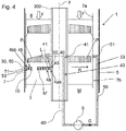
- FIG. 1 shown embodiment of the heat exchanger 1 according to the invention that the heat exchanger 1 is adapted to a portion of the gaseous phase G by means of a gas discharge 43 from the region of the inner tube layers 4a, 4aa from the Remove jacket space 6.
- a gas discharge 43 from the region of the inner tube layers 4a, 4aa from the Remove jacket space 6.
- the gas removal device 43 of the heat exchanger 1 at least one outflowing flow path 40 for the gaseous phase G with an inlet opening 41 arranged in the area of the inner pipe layers 4a in the shell space 6, wherein, for example, the at least one laxative flow path 40 through a pipe 30 an inner pipe layer 4a, in particular an innermost layer of pipe 4aa, the Tube bundle 3 is formed.
- the heat exchanger 1 or the gas discharge device 43 according to a second variant (see. FIG. 1 ) have an at least partially extending in an inner space of the core tube 300, laxative flow path 40 for the gaseous phase G, with an arranged in the region of the inner tube layers 4a in the shell space 6 inlet opening 41, which is formed in the present example, in a wall of the core tube 300.
- valve 8 is in the Fig. 1 only for the flow path 40 running in the interior of the core tube 300.
- the valve 8 is preferably set so that an actual temperature distribution measured in the jacket space 6 is approximated to a desired setpoint temperature distribution.
- the control can also be carried out so that a measured actual pressure distribution is approximated to a desired target pressure distribution.
- the temperature or the pressure can be measured in the jacket space, for example in a known manner by means of a light-conducting fiber L or other suitable sensors (see also above).
- a photoconductive fiber L may, for example, be laid along the tubes 30 and is in the FIG. 1 indicated schematically.
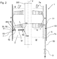
- FIG. 2 shows a modification of the in FIG. 1 shown embodiment, in contrast to FIG. 1 is provided, the gaseous phase G does not deduct in the region of the inner pipe layers 4a, 4aa from the shell space 6, but 4b, in particular in the region of the outermost layer of pipe 4b, in the shell space 6 initiate in the region of the outer pipe layers.
- the heat exchanger 1 a gas supply device 53 with at least one feeding flow path 50 for the gaseous phase G, which runs according to a first variant on the outside 7b of the shirt 7, as well as within the jacket space 6. It is of course also conceivable to have such a flow path 50 outside the jacket 5 to move and then pass through the jacket 5 and the shirt 7 therethrough. Furthermore, such a flow path 50 alternatively according to a likewise in the FIG. 2 shown second variant by a tube 30 of an outer tube layer 4b of the tube bundle 3, in particular by a tube 30 of an outermost tube layer 4bb of the tube bundle 3, be formed.
- the at least one feeding flow path 50 has an outlet opening 51 which is presently formed in the shirt 7 (or alternatively in said tube 30 of the outermost tube layer 4b, 4bb) so that the introduced gaseous phase G is the outermost one Pipe layer 4bb applied.
- the pressure in the jacket space 6 can be increased, in particular in the area of the outer pipe layers 4b, so that overall a pressure P which is as constant as possible in the radial direction R results.
- Also in the FIG. 2 can of course be provided along the longitudinal axis z a plurality of inlet openings 51, so that the pressure as above based on the FIG. 1 already described on the entire length of the tube bundle along the longitudinal axis z is positively influenced.
- valve 8 in particular both for the feeding flow path 50 having said tube 30 of the outermost tube layer 4b, 4bb and alternatively for that on the outside 7b of the shirt 7 extending feeder flow path 50.
- the valve 8 in the Fig. 2 only for the flow path 50 running on the outside 7b of the shirt 7.
- the valve 8 is preferably set in such a way that an actual pressure distribution P measured in the jacket space 6 or alternatively a measured actual temperature distribution is approximated to a corresponding desired pressure distribution or desired temperature distribution.
- FIG. 3 also the possibility of the respective embodiments according to FIG. 1 and FIG. 2 to combine, so that both a gaseous phase G of the first medium M from the shell space 6 is removable and can be fed.
- the two flow paths 40, 50 can be regulated Compressor 9 are in flow communication, so that a withdrawn from the shell space 6 in the region of the inner pipe layers 4a gaseous phase G by means of the compressor 9 is variably compressible and again in the shell space 6 in the region of the outer pipe layers 4b can be introduced.
- the gaseous medium G is guided in a circuit.
- the compressor 9 is for the sake of simplicity in the FIG.
- additional flow paths 40, 50 which in some embodiments according to FIGS. 1 to 4 can be used in addition to the tube bundle 3 to deduct a gaseous phase G spatially targeted from the shell space 6 or spatially targeted in the shell space 6 to specifically influence pressure or temperature gradients, in principle, such as above, of course, individual tubes 30 of the tube bundle 3 are used, which are located at the desired location, for example, a tube 30 from the outermost layer of tubes 4bb for introducing the gaseous phase G or a tube 30 from the innermost tube layer 4aa for discharging gaseous phase G.
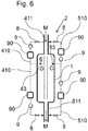
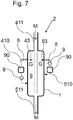
- FIGS. 6 and 7 Further embodiments of a heat exchanger 1 according to the invention or a system 2 comprising the heat exchanger 1, which relate to the interconnection of the gas discharge or gas supply means 43, 53.
- the heat exchanger 1 has a first line 411, via which the shell-side first medium M (in particular two-phase), for example, in an upper portion of the heat exchanger 1 and in the shell space 6 is fed.
- the shell-side first medium M in particular two-phase
- the heat exchanger 1 can have a second line 511, via which the shell-side first medium M can be removed from the jacket space 6 or heat exchanger.
- the second line 511 may be e.g. be provided at a lower portion of the heat exchanger 1.
- the gas discharge device 43 is connected to the first line 411 via a first flow connection 410, so that part of a gaseous phase G of the first medium M via the gas discharge device 43 and the first flow connection 410 the shell space 6 of the heat exchanger 1 is removable and can be fed into the first line 411.
- the gas discharge device 43 may be connected via a first flow connection 410 with the second line 511, so that a part of the gaseous phase G of the first medium M via the gas discharge 43 and the first flow connection 410 from the shell space 6 of the heat exchanger 1 is removable and in the second line 511 can be fed.
- the gas supply device 53 can also be connected to the first line 411 via a second flow connection 510, so that part of the gaseous phase G of the first medium M can be fed from the first line 411 into the gas supply device 53 via the second flow connection 510.
- the gas supply device 53 may be connected via a second flow connection 510 to the second line 511, so that part of the gaseous phase G of the first medium M from the second line 511 can be fed into the gas supply device 53 via the second flow connection 510.
- the first or the second flow connection 410, 510 can have a gas buffer store 90, a compressor 9 and, in particular, a valve 8, via which the flow of the gaseous phase G of the first medium M can be set or interrupted.
- the heat exchanger 1 thus forms here together with the respective gas storage tank 90, compressor 9 and valve 8 a process plant 2 or part of such a plant 2, in which the first medium M represents a process stream.
- the shell-side first medium M is a mixture of refrigerants.
- the first medium M can also be a process stream from another part of the plant 2.
- the gas discharge device 43 is connected at any point (in particular away from the two lines 411, 511) to the jacket space 6 of the heat exchanger 1 via the first flow connection 410, so that the first medium M is discharged via the gas discharge device 43 (and in particular via the valve 8, the gas buffer memory 90 and the compressor 9) can be pulled off the jacket space 6 and introduced back into the jacket space 6.
- the gas discharge device 43 is connected at any point (in particular away from the two lines 411, 511) to the jacket space 6 of the heat exchanger 1 via the first flow connection 410, so that the first medium M is discharged via the gas discharge device 43 (and in particular via the valve 8, the gas buffer memory 90 and the compressor 9) can be pulled off the jacket space 6 and introduced back into the jacket space 6.
- the gas supply means 53 via the second flow connection 510 also at any point (in particular off the two lines 411, 511) be connected to the shell space 6 of the heat exchanger 1, so that the first medium M via the second flow connection 510 (in particular via the gas buffer memory 90, the compressor 9 and the valve 8) can be removed from the shell space 6 and introduced back into the shell space 6 via the gas supply device 53.
- the in the FIGS. 6 and 7 Of course, flow connections 410, 510 shown can also be combined with one another in any desired manner.
Landscapes
- Engineering & Computer Science (AREA)
- Physics & Mathematics (AREA)
- Thermal Sciences (AREA)
- Mechanical Engineering (AREA)
- General Engineering & Computer Science (AREA)
- Heat-Exchange Devices With Radiators And Conduit Assemblies (AREA)
Applications Claiming Priority (1)
| Application Number | Priority Date | Filing Date | Title |
|---|---|---|---|
| EP17020286 | 2017-07-10 |
Publications (1)
| Publication Number | Publication Date |
|---|---|
| EP3428563A1 true EP3428563A1 (fr) | 2019-01-16 |
Family
ID=59315368
Family Applications (1)
| Application Number | Title | Priority Date | Filing Date |
|---|---|---|---|
| EP18020309.3A Withdrawn EP3428563A1 (fr) | 2017-07-10 | 2018-07-03 | Soutirage/injection de gaz destiné à influencer la migration radiale de liquide |
Country Status (4)
| Country | Link |
|---|---|
| US (1) | US20190011191A1 (fr) |
| EP (1) | EP3428563A1 (fr) |
| CN (1) | CN109237964A (fr) |
| RU (1) | RU2018125310A (fr) |
Cited By (2)
| Publication number | Priority date | Publication date | Assignee | Title |
|---|---|---|---|---|
| DE102018000468A1 (de) * | 2018-01-22 | 2019-07-25 | Linde Aktiengesellschaft | Gewickelter Wärmeübertrager mit Abscheider im Kernrohr |
| WO2022268360A1 (fr) * | 2021-06-23 | 2022-12-29 | Linde Gmbh | Injection réglable pour réaliser différentes distributions locales de fluide frigorigène |
Families Citing this family (3)
| Publication number | Priority date | Publication date | Assignee | Title |
|---|---|---|---|---|
| EP3719433A1 (fr) * | 2019-04-02 | 2020-10-07 | Linde GmbH | Distributeur de fluide réglable d'un échangeur de chaleur enroulé permettant de réaliser des différentes charges de fluide |
| CN113338844B (zh) | 2020-03-03 | 2023-04-25 | 中国石油天然气股份有限公司 | 金属可溶球座、坐封系统及坐封方法 |
| US20230147084A1 (en) | 2021-11-05 | 2023-05-11 | Air Products And Chemicals, Inc. | Mitigation of Shell-Side Liquid Maldistribution in Coil Wound Heat Exchanger Bundles |
Citations (4)
| Publication number | Priority date | Publication date | Assignee | Title |
|---|---|---|---|---|
| DE102004040974A1 (de) | 2004-08-24 | 2006-03-02 | Linde Ag | Gewickelter Wärmetauscher |
| EP2249112A2 (fr) * | 2009-05-07 | 2010-11-10 | Peter Huber Kältemaschinenbau Gmbh | Dispositif de réglage de la température d'un fluide d'ajustement de température |
| WO2015007375A1 (fr) * | 2013-07-16 | 2015-01-22 | Linde Aktiengesellschaft | Échangeur de chaleur muni d'un élément élastique |
| EP2857782A1 (fr) * | 2013-10-04 | 2015-04-08 | Shell International Research Maatschappij B.V. | Échangeur de chaleur à bobine enroulée et procédé de refroidissement d'un flux de procédé |
Family Cites Families (12)
| Publication number | Priority date | Publication date | Assignee | Title |
|---|---|---|---|---|
| SU411884A1 (fr) * | 1971-08-02 | 1974-01-25 | ||
| CH613274A5 (fr) * | 1976-11-17 | 1979-09-14 | Sulzer Ag | |
| DE3136589A1 (de) * | 1981-09-15 | 1983-03-31 | Bayer Ag | Temperierbarer statischer mischer und reaktor |
| US6770120B2 (en) * | 2002-05-01 | 2004-08-03 | Praxair Technology, Inc. | Radial adsorption gas separation apparatus and method of use |
| US6878186B2 (en) * | 2003-09-09 | 2005-04-12 | David Lloyd Neary | Pure vacuum swing adsorption system and apparatus |
| US7311763B2 (en) * | 2005-04-22 | 2007-12-25 | David Lloyd Neary | Gas separation vessel apparatus |
| TWI322882B (en) * | 2006-02-24 | 2010-04-01 | Lg Chemical Ltd | Annular distributor having guide vane to improve flow rate distribution, reactor/heat exchanger including the annular distributor and method of producing unsaturated aldehyde or unsaturated acid from olefin by catalytic gas phase oxidation in the reactor |
| IT1391947B1 (it) * | 2008-11-18 | 2012-02-02 | Euroklimat S P A | Evaporatore antigelo |
| US8313561B2 (en) * | 2010-10-05 | 2012-11-20 | Praxair Technology, Inc. | Radial bed vessels having uniform flow distribution |
| CN204952860U (zh) * | 2015-05-20 | 2016-01-13 | 武汉东海石化重型装备有限公司 | 一种立式缠绕管式反应器 |
| EP3159054B1 (fr) * | 2015-10-19 | 2018-08-29 | Nederman Holding AB | Évaporateur |
| US10378826B2 (en) * | 2016-10-14 | 2019-08-13 | Colmac Coil Manufacturing, Inc. | Heat Exchanger |
-
2018
- 2018-07-03 EP EP18020309.3A patent/EP3428563A1/fr not_active Withdrawn
- 2018-07-10 RU RU2018125310A patent/RU2018125310A/ru not_active Application Discontinuation
- 2018-07-10 CN CN201810750274.0A patent/CN109237964A/zh active Pending
- 2018-07-10 US US16/031,425 patent/US20190011191A1/en not_active Abandoned
Patent Citations (4)
| Publication number | Priority date | Publication date | Assignee | Title |
|---|---|---|---|---|
| DE102004040974A1 (de) | 2004-08-24 | 2006-03-02 | Linde Ag | Gewickelter Wärmetauscher |
| EP2249112A2 (fr) * | 2009-05-07 | 2010-11-10 | Peter Huber Kältemaschinenbau Gmbh | Dispositif de réglage de la température d'un fluide d'ajustement de température |
| WO2015007375A1 (fr) * | 2013-07-16 | 2015-01-22 | Linde Aktiengesellschaft | Échangeur de chaleur muni d'un élément élastique |
| EP2857782A1 (fr) * | 2013-10-04 | 2015-04-08 | Shell International Research Maatschappij B.V. | Échangeur de chaleur à bobine enroulée et procédé de refroidissement d'un flux de procédé |
Cited By (2)
| Publication number | Priority date | Publication date | Assignee | Title |
|---|---|---|---|---|
| DE102018000468A1 (de) * | 2018-01-22 | 2019-07-25 | Linde Aktiengesellschaft | Gewickelter Wärmeübertrager mit Abscheider im Kernrohr |
| WO2022268360A1 (fr) * | 2021-06-23 | 2022-12-29 | Linde Gmbh | Injection réglable pour réaliser différentes distributions locales de fluide frigorigène |
Also Published As
| Publication number | Publication date |
|---|---|
| CN109237964A (zh) | 2019-01-18 |
| US20190011191A1 (en) | 2019-01-10 |
| RU2018125310A (ru) | 2020-01-13 |
Similar Documents
| Publication | Publication Date | Title |
|---|---|---|
| EP2511642B1 (fr) | Echangeur thermique doté d'un réglage de liquide supplémentaire dans l'espace d'enveloppe | |
| EP1982819B1 (fr) | Procédé et dispositif de refroidissement d'un film tubulaire lors de la fabrication de feuilles soufflées | |
| DE69817477T2 (de) | Kühlvorrichtung für einen Abdeckring in einer Turbomaschine | |
| EP3430338B1 (fr) | Dispositif de separation pour un fluide caloporteur enroule destine a separer une phase gazeuse d'une phase liquide d'un milieu a deux phases achemine cote enveloppe | |
| EP3719434B1 (fr) | Distributeur de fluide réglable d'un échangeur de chaleur enroulé permettant de réaliser des différentes charges de fluide | |
| WO2008009357A1 (fr) | colonne d'Échange de matiÈre ou de chaleur comprenant des zones d'Échange de matiÈre et/ou de chaleur superposÉes comme des faisceaux tubulaires | |
| WO2006021315A1 (fr) | Echangeur thermique enroule | |
| EP3128278B1 (fr) | Amenee et extraction d'ecoulements tubulaires par temperature intermediaire pour des echangeurs de chaleur a bobines | |
| EP2912394B1 (fr) | Échangeur de chaleur avec plusieures entrées et procédé d'adaption de la surface chauffante de l'échangeur thermique | |
| EP1528134A2 (fr) | Dispositif et procédé pour le traitement d'un fil en mouvement avec une vapeur | |
| DE19518323A1 (de) | Verfahren und Vorrichtung zum unterbrechungsfreien Wärmetausch | |
| EP3443287B1 (fr) | Fluide caloporteur enroule | |
| WO2017167458A1 (fr) | Echangeur de chaleur à spirales | |
| EP0048325A2 (fr) | Refroidisseur de gaz chauds comprenant un récipient de pression | |
| EP2052839B1 (fr) | Dispositif doté d'un anneau de gaz de refroidissement principal doté d'une unité de redresseur et d'un anneau de gaz de refroidissement supplémentaire | |
| DE4412563A1 (de) | Einrichtung und Verfahren zum Kühlen einer zu fertigenden Lichtleitfaser | |
| DE102014000539A1 (de) | Verdampfer | |
| DE202023101698U1 (de) | Folienblasanlage | |
| DE2813808C2 (fr) | ||
| DE102012005569A1 (de) | Wärmetauscher mit Sektionen | |
| EP4359718B1 (fr) | Injection réglable pour réaliser différentes distributions locales de fluide frigorigène | |
| DE102011015433A1 (de) | Wärmetauschersystem | |
| EP4337908B1 (fr) | Échangeur de chaleur enveloppé et procédé | |
| EP3088159B1 (fr) | Anneau de refroidissement et procédé de refroidissement externe d'une feuille tubulaire en matière synthétique thermoplastique lors de sa production | |
| DE3439051A1 (de) | Stoffauflaufvorrichtung fuer eine papiermaschine |
Legal Events
| Date | Code | Title | Description |
|---|---|---|---|
| PUAI | Public reference made under article 153(3) epc to a published international application that has entered the european phase |
Free format text: ORIGINAL CODE: 0009012 |
|
| STAA | Information on the status of an ep patent application or granted ep patent |
Free format text: STATUS: THE APPLICATION HAS BEEN PUBLISHED |
|
| AK | Designated contracting states |
Kind code of ref document: A1 Designated state(s): AL AT BE BG CH CY CZ DE DK EE ES FI FR GB GR HR HU IE IS IT LI LT LU LV MC MK MT NL NO PL PT RO RS SE SI SK SM TR |
|
| AX | Request for extension of the european patent |
Extension state: BA ME |
|
| STAA | Information on the status of an ep patent application or granted ep patent |
Free format text: STATUS: REQUEST FOR EXAMINATION WAS MADE |
|
| 17P | Request for examination filed |
Effective date: 20190624 |
|
| RBV | Designated contracting states (corrected) |
Designated state(s): AL AT BE BG CH CY CZ DE DK EE ES FI FR GB GR HR HU IE IS IT LI LT LU LV MC MK MT NL NO PL PT RO RS SE SI SK SM TR |
|
| STAA | Information on the status of an ep patent application or granted ep patent |
Free format text: STATUS: EXAMINATION IS IN PROGRESS |
|
| 17Q | First examination report despatched |
Effective date: 20200506 |
|
| RAP1 | Party data changed (applicant data changed or rights of an application transferred) |
Owner name: LINDE GMBH |
|
| GRAP | Despatch of communication of intention to grant a patent |
Free format text: ORIGINAL CODE: EPIDOSNIGR1 |
|
| STAA | Information on the status of an ep patent application or granted ep patent |
Free format text: STATUS: GRANT OF PATENT IS INTENDED |
|
| INTG | Intention to grant announced |
Effective date: 20210225 |
|
| STAA | Information on the status of an ep patent application or granted ep patent |
Free format text: STATUS: THE APPLICATION IS DEEMED TO BE WITHDRAWN |
|
| 18D | Application deemed to be withdrawn |
Effective date: 20210708 |