EP3443287B1 - Fluide caloporteur enroule - Google Patents
Fluide caloporteur enroule Download PDFInfo
- Publication number
- EP3443287B1 EP3443287B1 EP17717327.5A EP17717327A EP3443287B1 EP 3443287 B1 EP3443287 B1 EP 3443287B1 EP 17717327 A EP17717327 A EP 17717327A EP 3443287 B1 EP3443287 B1 EP 3443287B1
- Authority
- EP
- European Patent Office
- Prior art keywords
- tube
- spacer
- heat exchanger
- medium
- layer
- Prior art date
- Legal status (The legal status is an assumption and is not a legal conclusion. Google has not performed a legal analysis and makes no representation as to the accuracy of the status listed.)
- Not-in-force
Links
Images



Classifications
-
- F—MECHANICAL ENGINEERING; LIGHTING; HEATING; WEAPONS; BLASTING
- F28—HEAT EXCHANGE IN GENERAL
- F28D—HEAT-EXCHANGE APPARATUS, NOT PROVIDED FOR IN ANOTHER SUBCLASS, IN WHICH THE HEAT-EXCHANGE MEDIA DO NOT COME INTO DIRECT CONTACT
- F28D7/00—Heat-exchange apparatus having stationary tubular conduit assemblies for both heat-exchange media, the media being in contact with different sides of a conduit wall
- F28D7/02—Heat-exchange apparatus having stationary tubular conduit assemblies for both heat-exchange media, the media being in contact with different sides of a conduit wall the conduits being helically coiled
- F28D7/024—Heat-exchange apparatus having stationary tubular conduit assemblies for both heat-exchange media, the media being in contact with different sides of a conduit wall the conduits being helically coiled the conduits of only one medium being helically coiled tubes, the coils having a cylindrical configuration
-
- F—MECHANICAL ENGINEERING; LIGHTING; HEATING; WEAPONS; BLASTING
- F28—HEAT EXCHANGE IN GENERAL
- F28D—HEAT-EXCHANGE APPARATUS, NOT PROVIDED FOR IN ANOTHER SUBCLASS, IN WHICH THE HEAT-EXCHANGE MEDIA DO NOT COME INTO DIRECT CONTACT
- F28D7/00—Heat-exchange apparatus having stationary tubular conduit assemblies for both heat-exchange media, the media being in contact with different sides of a conduit wall
- F28D7/02—Heat-exchange apparatus having stationary tubular conduit assemblies for both heat-exchange media, the media being in contact with different sides of a conduit wall the conduits being helically coiled
- F28D7/022—Heat-exchange apparatus having stationary tubular conduit assemblies for both heat-exchange media, the media being in contact with different sides of a conduit wall the conduits being helically coiled the conduits of two or more media in heat-exchange relationship being helically coiled, the coils having a cylindrical configuration
-
- F—MECHANICAL ENGINEERING; LIGHTING; HEATING; WEAPONS; BLASTING
- F28—HEAT EXCHANGE IN GENERAL
- F28F—DETAILS OF HEAT-EXCHANGE AND HEAT-TRANSFER APPARATUS, OF GENERAL APPLICATION
- F28F13/00—Arrangements for modifying heat-transfer, e.g. increasing, decreasing
- F28F13/06—Arrangements for modifying heat-transfer, e.g. increasing, decreasing by affecting the pattern of flow of the heat-exchange media
-
- F—MECHANICAL ENGINEERING; LIGHTING; HEATING; WEAPONS; BLASTING
- F28—HEAT EXCHANGE IN GENERAL
- F28F—DETAILS OF HEAT-EXCHANGE AND HEAT-TRANSFER APPARATUS, OF GENERAL APPLICATION
- F28F9/00—Casings; Header boxes; Auxiliary supports for elements; Auxiliary members within casings
- F28F9/007—Auxiliary supports for elements
- F28F9/013—Auxiliary supports for elements for tubes or tube-assemblies
- F28F9/0132—Auxiliary supports for elements for tubes or tube-assemblies formed by slats, tie-rods, articulated or expandable rods
-
- F—MECHANICAL ENGINEERING; LIGHTING; HEATING; WEAPONS; BLASTING
- F28—HEAT EXCHANGE IN GENERAL
- F28F—DETAILS OF HEAT-EXCHANGE AND HEAT-TRANSFER APPARATUS, OF GENERAL APPLICATION
- F28F9/00—Casings; Header boxes; Auxiliary supports for elements; Auxiliary members within casings
- F28F9/22—Arrangements for directing heat-exchange media into successive compartments, e.g. arrangements of guide plates
Definitions
- the invention relates to a wound heat exchanger.
- Such a heat exchanger is used for indirect heat transfer between at least a first and a second medium and has a shell space for receiving the first medium, as well as a tube bundle arranged in the shell space with a plurality of tubes for receiving the second medium, those tubes being helical in several tube layers are wound on a core tube of the heat exchanger.
- DE-A-1939564 discloses such a heat exchanger and furthermore a heat exchanger according to the preamble of claim 1.
- Spacers are preferably provided between the pipe layers, via which the respective pipe layer is supported on the pipe layers below.
- the first medium guided in the shell space over the tube bundle it is of particular importance that the first medium is distributed as evenly as possible over the tube bundle in order to be able to ensure efficient heat transfer.
- the fluid first medium guided on the jacket side is passed outward to the outer pipe layers (in the radial direction of the pipe bundle) due to various effects in the jacket space.
- One of the reasons for this is the centrifugal force which, due to the helical winding of the individual tubes of the tube bundle of the heat exchanger, acts on the parts of the first medium flowing along the surfaces of the tubes.
- these parts of the first medium are forced outward in the radial direction of the tube bundle towards the outer tube layers.
- an uneven distribution of the first medium is generated in favor of the outer tube layers.
- the present invention is therefore based on the object of creating a heat exchanger of the type mentioned at the beginning which counteracts the aforementioned problems.
- a heat exchanger for indirect heat transfer between a first and a second medium is provided with a shell space for receiving the first medium, a tube bundle arranged in the shell space with a plurality of tubes for receiving the second medium, the respective tube being helically wound onto a core tube , so that the tube bundle has several tube layers arranged on top of one another, and at least one spacer via which a first tube layer of the tube bundle located further out in the radial direction of the tube bundle is supported on an adjacent second tube layer further inside in the radial direction of the tube bundle.
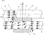
- the at least one spacer has a flow-guiding means. This has the effect that a part of the first medium flowing in the jacket space along the first (outer) and / or the second (inner) pipe layer is deflected in the direction of the pipe layer located radially further inward.
- the flow-guiding means has an end face of the spacer which connects a front side of the spacer facing away from the core tube with a rear side of the spacer facing the core tube, the end face having an inclination towards the second pipe layer, so that a front side of the spacer facing away from the core tube first pipe layer against the end face of the flowing part of the first medium is deflected by the end face in the direction of the second pipe layer.
- the flow-guiding means has at least one guiding element which is fixed on a base of the spacer that extends along the longitudinal axis and over which the first pipe layer extends on the second Supports pipe layer, wherein the at least one guide element forms an impact surface which has an inclination towards the second pipe layer.
- the pipe layer further out does not necessarily have to be the outermost pipe layer.
- a large number of pipe layers can of course be provided in the heat exchanger according to the invention (see also below), in which case one or more spacers with said flow-guiding means can be provided between each two (in the radial direction) adjacent pipe layers, with the flow of the respective Part of the first medium is always directed from the (first) pipe layer located radially further outside to the adjacent (second) pipe layer located radially further inside.
- the spacer elements with said flow-guiding means are provided in such a way that the first medium is distributed as evenly as possible over the tube bundle (based on the entire length of the tube bundle along the longitudinal axis of the shell / core tube of the heat exchanger).
- spacers are not provided between all pipe layers, but only between certain pipe layers (depending on the expected uneven distribution of the first medium).
- Conventional spacers for example, or spacers which do not show the flow-deflecting effect according to the invention or show the flow-deflecting effect to a much lesser extent, can then be provided between the remaining pipe layers.
- the invention advantageously counteracts the uneven distribution in favor of the outer pipe layers, so that as a result the jacket-side coolant or the first medium is better distributed and the performance of the wound heat exchanger is improved accordingly.
- the flow-guiding means has an end face of the at least one spacer.
- This end face is preferably an integral component of the at least one spacer or a side of the spacer formed in one piece with the spacer.
- the front side connects a front side of the spacer facing away from the core tube with a rear side of the spacer facing the core tube.
- the front side extends thus essentially along the radial direction of the tube bundle and in particular has an inclination with respect to the radial direction.
- said end face can also extend in sections between two adjacent pipe sections of the first pipe layer, these sections of the end face each being part of a projection of the spacer element, these projections each being between two adjacent pipe sections or pipe coils of the first pipe layer and each from an edge portion of a base of the at least one spacer protrude in the radial direction of the tube bundle).
- the vertical spacing of the pipe windings in the respective pipe layer is thus fixed by these projections.
- the said end face of the at least one spacer for influencing or deflecting the flow of the first medium has an inclination towards the second pipe layer or an inclination with respect to a tangential direction of the pipe sections of the second pipe layer resting on the spacer so that the part of the first medium flowing along the pipe of the first pipe layer against the end face of the at least one spacer is deflected by the end face in the direction of the second pipe layer.
- the core tube extends along a longitudinal axis which is preferably oriented parallel to the vertical, in relation to a heat exchanger arranged as intended.
- the heat exchanger preferably also has a jacket surrounding the jacket space, which extends coaxially to the core tube along the said longitudinal axis.
- the at least one spacer or the said flow-influencing end face of the spacer extends along the longitudinal axis.
- the flow-guiding means has at least one guide element, for example in the form of at least one guide plate, which is fixed to a base of the spacer extending along the longitudinal axis, via which the first pipe layer is supported on the second pipe layer.
- the basis takes over the production of the distance between the individual pipe layers or the transfer of the load of the respective outer pipe layer to the pipe layer underneath, while the at least one guide element preferably only takes on a flow-guiding function.
- the at least one guide element forms an impact surface on which the said deflecting part of the first medium impinges, with that impact surface again having an inclination towards the second pipe layer (or an inclination in relation to a tangential direction of the the spacer adjacent pipe sections of the second pipe layer).
- the guide element extends in sections between adjacent pipe sections of the second pipe layer or the pipe layer located radially further inward.
- the at least one spacer can also have a plurality of guide elements which are fixed to the base along the longitudinal axis, so that there is a gap between every two guide elements adjacent in the direction of the longitudinal axis.
- the individual guide elements then extend in sections between each two associated pipe sections of the second pipe layer or protrude into a space between the two pipe sections.
- the at least one guide element (or the plurality of guide elements) is arranged on an upstream or downstream section of the base of the at least one spacer in relation to the flow direction of the first medium, in particular on an end face of the base which connects a front of the base to a rear of the base, the rear facing the core tube.
- said means is formed by a plurality of grooves formed in the spacer or has such grooves.
- the channels each extend inwards along the radial direction, sloping inwards so that a part of the first medium flowing along the first pipe layer, in particular from top to bottom, can get into the channels and inwards to the second pipe layer is distracted.
- the grooves are formed, for example, on an end face of the respective spacer against which that along the first pipe layer or the first medium flowing along the pipe of the first pipe layer flows or on which the first medium flows down from top to bottom.
- a spacer can thus have one, two or three of the aforementioned components for directing the flow.
- the heat exchanger has a plurality of spacer elements between the first and the second pipe layer, the spacer elements each having a flow-guiding means which is designed according to one of the embodiments described or claimed herein.
- the heat exchanger has spacer elements between several or between all adjacent pipe layers, the respective spacer element preferably having a flow-guiding means which is designed according to one of the embodiments described or claimed herein.
- the number of spacers arranged between the adjacent pipe layers is constant, with a plurality of spacers each being arranged one above the other to support the pipe layers in a radial direction of the pipe bundle. In this way, the weight of all pipe layers can be supported by the spacers without damaging the pipes of individual pipe layers.
- Fig. 1 shows a wound heat exchanger 1.
- This has a jacket 10 which encloses a jacket space M of the heat exchanger 1.
- the jacket 10 extends along a vertical longitudinal or cylinder axis L and surrounds a tube bundle 2, which is arranged in the jacket space M and is to be acted upon from above with a fluid first medium S in relation to the longitudinal axis L, so that this is in indirect heat transfer with at least a second medium S 'guided in the tube bundle 2.
- the tube bundle 2 is formed from several tubes 20, each of which is helically wound around a core tube 21, so that the tube bundle has several tube layers 201, 202, ... arranged one above the other in the radial direction R of the tube bundle 2 (cf. Figures 2 to 4 ).
- the core tube 21 extends coaxially to the jacket 10, the radial direction R of the tube bundle 2 being perpendicular to the longitudinal axis L or the core tube 21 and pointing outwards to the jacket 10.
- the pipe layers 201, 202,. 202, ... are introduced into the core tube 21 via the spacers 6.
- the tube bundle 2 can furthermore be surrounded by a so-called shirt 3 in order to prevent the first medium S from flowing past the tube bundle 2 on the outside.
- the first medium S can enter the jacket space M via a connector 101 provided laterally on the jacket 10, for example fed in and withdrawn from the jacket space M via a further connector 102 provided laterally on the jacket 10.
- a distribution device not shown here, eg of a known type, can be provided in the shell space M above the tube bundle 2.
- the second medium S ′ carried in the tube bundle 2 can furthermore be introduced into the tube bundle 2 via a connection 103 provided on the jacket 10 and withdrawn from the tube bundle 2 via a further connection 105 provided on the jacket 10.
- the tubes 20 can be combined into corresponding groups 104, which then each carry one of the media.
- the heat exchanger 1 has at least one spacer 6, via which a first pipe layer 201 located further outside in the radial direction R of the tube bundle 2 extends to a second pipe layer 201 located further inside in the radial direction R.
- Pipe layer 202, the spacer 6 having a flow-guiding means 6a which is configured to deflect a part of the first medium S flowing in the jacket space M along a pipe 20 of the first pipe layer 201 in the direction of the second pipe layer 202 further inside.
- This means 6a is, for example, an end face 6a of the spacer 6 which connects a front side 6b of the spacer 6 facing away from the core tube 21 with a rear side 6c of the spacer 6 facing the core tube 21, said end face 6a being inclined to the second pipe layer 202, so that the part of the first medium S flowing along the pipe 20 of the first pipe layer 201 against the end face 6a is deflected by the end face 6a in the direction of the second pipe layer 202.
- the inclination of the end face 6a with respect to the first pipe layer 201 is characterized here by an acute angle W which the second end face 6a has of the second pipe layer 202 or the pipe sections of the second pipe layer 202 adjoining the spacer 6.
- a plurality of spacers 6 of the type described above is preferably provided between each two adjacent pipe layers 201, 202, ..., the number of spacers 6 arranged between two pipe layers 201, 202, different pipe layers are preferably arranged one above the other in the radial direction R so that the load of the pipe layers 201, 202,.
- the tubes 20 in the tube layers 201, 202,... can have different winding directions.
- the first medium S in the adjacent pipe layers 201, 202 can flow in a different direction along the respective pipe 20.
- the end face 6a of the respective spacer 6 is then aligned in such a way that the respective inwardly directed portion of the first medium S flows against the respective end face 6a.
- the at least one or the respective spacer 6 can have projections 61 which protrude outward in the radial direction R from an edge portion of a base 60 of the respective spacer 6. These projections 61 serve to produce a desired vertical spacing between the pipe windings in the respective pipe layer. Furthermore, the projections 61 can form part of the end face 6 a of the respective spacer 6. The end face 6a of the respective spacer 6 can thus be arranged at least in sections between the adjacent pipe sections of the pipe layer 201 located further out.
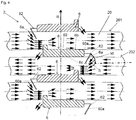
- the Figure 3 shows a further embodiment of the invention, in which the at least one spacer 6 has at least one guide element 62, for example in the form of a guide plate, which is fixed to a (e.g. bar-shaped) base 60 of the at least one spacer 6 that extends along the longitudinal axis L.
- the at least one spacer 6 has at least one guide element 62, for example in the form of a guide plate, which is fixed to a (e.g. bar-shaped) base 60 of the at least one spacer 6 that extends along the longitudinal axis L.
- the base 60 takes on the load-bearing function, that is, the (first) pipe layer 201 arranged further out is supported on the (second) pipe layer 202 below it via this base 60, while the guide element 62 preferably has the flow-guiding or deflecting function takes over and said means 6a of the spacer 6, which is designed here as an impact surface 6a of the guide element 62, which has an inclination towards the (second) pipe layer 202 located further inward in the radial direction R (or an inclination towards the adjacent pipe sections of the second pipe layer 202) . Due to the inclination, the impact surface 6a of the guide element 62 forms an acute angle W with the (second) pipe layer 202 located radially further inward.
- the guide element 62 can be a separate element that is fixed to the base 60 of the respective spacer 6, preferably on an end face 60a of the base 60, the rear side facing the core tube 21, on which the further inward (second) tube layer 202 rests, connects to a front side of the base 60, on which the further outward (first pipe layer) 201 rests.
- the guide element 62 can, however, also be embodied integrally with the base 60 (in one piece).
- Analogous to Figure 2 can also according to Figure 3
- a plurality of spacers 6 can be provided, the spacers 6 from different pipe layers preferably being arranged one above the other in the radial direction R (see above).
- FIG 3 a situation is shown in which the flow direction of that part of the first medium S which flows along the pipe 20 of the respective pipe layer 201, 202
- the respective guide element 62 is provided or fixed on a downstream end face 60a of the base 60 of the respective spacer 6 in relation to the flow direction of the part of the first medium S to be deflected.
- Said baffle surface 6a is in particular facing the respective base 60 and in particular ensures a deflection of a part of the first medium S after this part has passed the respective base 60 on the rear side of the respective base 60.
- Figure 4 shows a modification of the guide elements 62, here in contrast to Figure 3 the guide elements 62 are each provided on an upstream end face 60a of the base 60 of the respective spacer 6, and here the impact surface 6a of the respective guide element 62 from the associated base 60 is turned away and has an inclination with respect to the (second) pipe layer 202 located further inward, so that it encloses an acute angle W with it.
- the guide element 62 of the respective spacer 6 extends in sections between adjacent pipe sections of the pipe layer 202 located further inside.
- the respective spacer 6 can be used in both embodiments ( Fig. 3 and Fig. 4 ) also have a corresponding plurality of guide elements 62, which then each protrude into the space between two adjacent pipe sections of the pipe layer 202,.
- FIG. 5 shows Figure 5 an embodiment of spacers 6 according to the invention which, as before, are arranged between adjacent pipe layers 201, 202, ... of the heat exchanger 1 (see above), the flow-guiding means 6a being formed here by channels 6a (or having such channels), each of which are designed to direct a portion of the first medium S flowing from top to bottom along the first or outer pipe layer 201 in the direction of the second or radially further inward pipe layer 202.
- the said channels preferably slope towards the (second) pipe layer 202 located further inside.
- the grooves 6a can be provided, for example, on an end face 60a of the respective spacer 6 or a base of the respective spacer 6.
- the spacers 6 can furthermore in turn have projections 61 protruding from the respective base 60 in the radial direction R, which define a vertical distance between adjacent pipe windings or adjacent pipe sections of the pipes 20 in the direction of the longitudinal axis L of the jacket.
- the spacers 60 can only have the said grooves 6a as flow-guiding means. Said grooves 6a, however, can also be used in the spacers 6 of the Figures 1 to 4 be available as additional flow-guiding components.
Landscapes
- Engineering & Computer Science (AREA)
- Physics & Mathematics (AREA)
- Thermal Sciences (AREA)
- Mechanical Engineering (AREA)
- General Engineering & Computer Science (AREA)
- Heat-Exchange Devices With Radiators And Conduit Assemblies (AREA)
Claims (10)
- Échangeur de chaleur (1) pour le transfert de chaleur indirect entre un premier et un second fluides (S, S'), comprenant- une calandre (M) pour la réception du premier fluide (S),- un faisceau de tubes (2) agencé dans la calandre (M) comprenant une pluralité de tubes (20) pour la réception du second fluide (S'), dans lequel le tube respectif (20) est enroulé de manière hélicoïdale sur un tube central, de sorte que le faisceau de tubes (2) présente plusieurs supports de tube (201, 202, 203) agencés les uns sur les autres et- au moins un écarteur (6), par le biais duquel un premier support de tube (201) du faisceau de tubes (2) situé plus à l'extérieur dans une direction radiale (R) du faisceau de tubes (2) s'appuie sur un deuxième support de tube (202) voisin, situé plus à l'intérieur dans la direction radiale (R) du faisceau de tubes (2) et dans lequel l'au moins un écarteur (6) présente un agent conducteur d'écoulement (6a),caractérisé en ce que
l'agent (6a) présente un côté frontal (6a) de l'écarteur (6), qui relie un côté avant (6b) de l'écarteur (6) à l'opposé du tube central (21) avec un côté arrière (6c) de l'écarteur (6) tourné vers le tube central (21), dans lequel le côté frontal (6a) présente une inclinaison jusqu'au deuxième support de tube (202), de sorte qu'une partie du premier fluide (S) circulant le long du tube (20) du premier support de tube (201) contre le côté frontal (6a) soit déviée par le côté frontal (6a) en direction du deuxième support de tube (202),
ou en ce que
l'agent (6a) présente au moins un élément conducteur (62), qui est fixé sur une base (60) de l'écarteur (6) s'étendant le long de l'axe longitudinal (L), par le biais de laquelle le premier support de tube (201) s'appuie sur le deuxième support de tube (202), dans lequel l'au moins un élément conducteur (62) forme un déflecteur (6a), qui présente une inclinaison vers le deuxième support de tube (202). - Échangeur de chaleur selon la revendication 1, caractérisé en ce que l'au moins un élément conducteur (62) s'étend par section entre des sections de tubes adjacentes du deuxième support de tube (202).
- Échangeur de chaleur selon l'une quelconque des revendications 1 à 2, caractérisé en ce que l'au moins un élément conducteur (62) est disposé, par rapport à la direction d'écoulement du premier fluide (S), sur une section de bord (60a) de l'écarteur (6) située en amont ou en aval.
- Échangeur de chaleur selon l'une quelconque des revendications précédentes, caractérisé en ce que le tube central (21) s'étend le long d'un axe longitudinal (L).
- Échangeur de chaleur selon la revendication 4, caractérisé en ce que l'échangeur de chaleur (1) présente une gaine (10) entourant la calandre (M), qui s'étend de manière coaxiale au tube central (21) le long de l'axe longitudinal (L).
- Échangeur de chaleur selon la revendication 4 ou 5, caractérisé en ce que l'au moins un écarteur (6) et/ou ledit agent (6a) s'étend le long de l'axe longitudinal (L).
- Échangeur de chaleur selon l'une quelconque des revendications précédentes, caractérisé en ce que l'agent présente une pluralité de rainures (6a) prévues sur l'au moins un écarteur (6), qui sont conçues pour diriger une partie du premier fluide (S) s'écoulant le long du premier support de tube (201) de haut en bas en direction du deuxième support de tube (202).
- Échangeur de chaleur selon l'une quelconque des revendications précédentes, caractérisé en ce que l'échangeur de chaleur (1) présente une pluralité d'éléments d'écartement (6) entre le premier et le deuxième support de tube (201, 202), dans lequel les éléments d'écartement (6) présentent respectivement un agent conducteur d'écoulement (6a) selon l'une quelconque des revendications précédentes.
- Échangeur de chaleur selon l'une quelconque des revendications précédentes, caractérisé en ce que l'échangeur de chaleur (1) présente des éléments d'écartement (6) entre plusieurs ou entre tous les supports de tube (201, 202, 203) voisins de l'échangeur de chaleur (1), dans lequel l'élément d'écartement (6) respectif présente un agent conducteur d'écoulement (6a) selon l'une quelconque des revendications précédentes.
- Échangeur de chaleur selon la revendication 9, caractérisé en ce que le nombre d'écarteurs (6) agencés entre les supports de tube (201, 202, 203) voisins est constant, dans lequel respectivement plusieurs écarteurs (6) sont agencés les uns sur les autres pour supporter les supports de tube (201, 202, 203) dans une direction radiale (R) du faisceau de tubes (2).
Applications Claiming Priority (2)
| Application Number | Priority Date | Filing Date | Title |
|---|---|---|---|
| EP16000851 | 2016-04-14 | ||
| PCT/EP2017/025090 WO2017178120A1 (fr) | 2016-04-14 | 2017-04-12 | Échangeur de chaleur enroulé |
Publications (2)
| Publication Number | Publication Date |
|---|---|
| EP3443287A1 EP3443287A1 (fr) | 2019-02-20 |
| EP3443287B1 true EP3443287B1 (fr) | 2021-12-08 |
Family
ID=55759435
Family Applications (1)
| Application Number | Title | Priority Date | Filing Date |
|---|---|---|---|
| EP17717327.5A Not-in-force EP3443287B1 (fr) | 2016-04-14 | 2017-04-12 | Fluide caloporteur enroule |
Country Status (5)
| Country | Link |
|---|---|
| US (1) | US10823508B2 (fr) |
| EP (1) | EP3443287B1 (fr) |
| CN (1) | CN108885065B (fr) |
| RU (1) | RU2727110C2 (fr) |
| WO (1) | WO2017178120A1 (fr) |
Families Citing this family (4)
| Publication number | Priority date | Publication date | Assignee | Title |
|---|---|---|---|---|
| WO2020083524A1 (fr) * | 2018-10-23 | 2020-04-30 | Linde Aktiengesellschaft | Procédé de fabrication d'un échangeur de chaleur enroulé |
| WO2020083523A1 (fr) * | 2018-10-23 | 2020-04-30 | Linde Aktiengesellschaft | Procédé de fabrication d'un échangeur de chaleur enroulé |
| EP3964372A1 (fr) * | 2020-09-03 | 2022-03-09 | TI Automotive Technology Center GmbH | Agencement de conduites pour le transport des milieux de mise à la température |
| WO2022117129A1 (fr) * | 2020-12-01 | 2022-06-09 | Vysoké Učení Technické V Brně | Échangeur de chaleur à coque tubulaire et à écoulement transversal |
Family Cites Families (39)
| Publication number | Priority date | Publication date | Assignee | Title |
|---|---|---|---|---|
| BE599070A (fr) * | 1960-01-22 | |||
| US3286767A (en) * | 1964-10-01 | 1966-11-22 | Babcock & Wilcox Co | Tube support arrangement |
| DE1939564A1 (de) * | 1968-08-06 | 1970-02-12 | Atomic Power Construction Ltd | Aufhaengesystem fuer Vielfach-Rohranordnungen,insbesondere in Waermetauschern von Kernreaktoren |
| US3677339A (en) * | 1970-01-15 | 1972-07-18 | Alfred J Perrin | Coiled tube banks |
| DE2613745A1 (de) * | 1976-03-31 | 1977-10-06 | Linde Ag | Waermetauscher |
| SU901795A1 (ru) * | 1980-04-04 | 1982-01-30 | Предприятие П/Я Г-4882 | Спиральный теплообменник |
| DE3403429A1 (de) * | 1984-02-01 | 1985-08-08 | Karl 7298 Loßburg Hehl | Kuehlereinheit fuer kunststoff-spritzgiessmaschine |
| CH665020A5 (de) * | 1984-08-15 | 1988-04-15 | Sulzer Ag | Waermeuebertrager. |
| US5088192A (en) * | 1986-02-21 | 1992-02-18 | Aqua Systems, Inc. | Method of forming a shell and coil heat exchanger |
| US5228505A (en) * | 1986-02-21 | 1993-07-20 | Aqua Systems Inc. | Shell and coil heat exchanger |
| US5379832A (en) * | 1992-02-18 | 1995-01-10 | Aqua Systems, Inc. | Shell and coil heat exchanger |
| US5578231A (en) * | 1992-06-06 | 1996-11-26 | Barmag Ag | Heater for an advancing yarn |
| RU2050525C1 (ru) * | 1993-11-11 | 1995-12-20 | Лариса Ростиславовна Комарова | Теплообменник |
| US6076597A (en) * | 1997-12-31 | 2000-06-20 | Flowserve Management Company | Helical coil heat exchanger with removable end plates |
| RU2262054C2 (ru) * | 1999-02-01 | 2005-10-10 | Олесевич Алексей Кириллович | Теплообменный аппарат |
| JP2002097946A (ja) * | 2000-09-25 | 2002-04-05 | Honda Motor Co Ltd | 内燃機関の廃熱回収装置 |
| DE10123219A1 (de) * | 2001-05-12 | 2003-01-16 | Bosch Gmbh Robert | Wärmetauscher zum Erwärmen eines Produktes, insbesondere einer Masse zur Herstellung von Süßwaren |
| JP3524083B2 (ja) * | 2001-11-16 | 2004-04-26 | 核燃料サイクル開発機構 | 中間熱媒体を有するヘリカル型熱交換器 |
| RU2192593C1 (ru) * | 2001-12-11 | 2002-11-10 | Закрытое акционерное общество "ОРМА" | Спиральный теплообменник |
| US6827138B1 (en) * | 2003-08-20 | 2004-12-07 | Abb Lummus Global Inc. | Heat exchanger |
| DE112005001061T5 (de) * | 2004-05-11 | 2008-11-06 | Noritz Corporation, Kobe | Wärmetauscher und Wasserheizvorrichtung |
| US20060108107A1 (en) * | 2004-11-19 | 2006-05-25 | Advanced Heat Transfer, Llc | Wound layered tube heat exchanger |
| US10495383B2 (en) * | 2004-11-19 | 2019-12-03 | Modine Grenada Llc | Wound layered tube heat exchanger |
| US20090301699A1 (en) * | 2008-06-05 | 2009-12-10 | Lummus Novolent Gmbh/Lummus Technology Inc. | Vertical combined feed/effluent heat exchanger with variable baffle angle |
| GB2463482B (en) * | 2008-09-12 | 2012-05-02 | Tanjung Citech Uk Ltd | A heat exchange unit |
| US20100096115A1 (en) | 2008-10-07 | 2010-04-22 | Donald Charles Erickson | Multiple concentric cylindrical co-coiled heat exchanger |
| AU2013284326B2 (en) * | 2012-06-29 | 2017-07-27 | Waterco Limited | Heat exchanger |
| DE102012014101A1 (de) * | 2012-07-17 | 2014-01-23 | Linde Aktiengesellschaft | Gewickelter Wärmeübertrager |
| US20140262172A1 (en) * | 2013-03-14 | 2014-09-18 | Koch Heat Transfer Company, Lp | Tube bundle for shell-and-tube heat exchanger and a method of use |
| WO2015007375A1 (fr) * | 2013-07-16 | 2015-01-22 | Linde Aktiengesellschaft | Échangeur de chaleur muni d'un élément élastique |
| HK1189328A2 (en) * | 2013-09-30 | 2014-05-30 | 香港现代科技有限公司 | Fluid heat exchanger and energy recovery device |
| CN104596333B (zh) * | 2013-10-31 | 2017-09-15 | 台达电子工业股份有限公司 | 热交换机 |
| SE538978C2 (sv) * | 2014-04-14 | 2017-03-07 | Milton Mogens | Värmeväxlare |
| US20160018168A1 (en) * | 2014-07-21 | 2016-01-21 | Nicholas F. Urbanski | Angled Tube Fins to Support Shell Side Flow |
| CN204404855U (zh) * | 2014-11-26 | 2015-06-17 | 中国海洋石油总公司 | 一种腔体内设置竖直隔板的缠绕管式换热器 |
| CA2882516C (fr) * | 2015-02-20 | 2016-02-23 | Robert M. Myerholtz | Appareil de chauffage de bobine helicoidale et mode d'utilisation |
| EP3128278B1 (fr) * | 2015-08-06 | 2018-06-20 | Linde Aktiengesellschaft | Amenee et extraction d'ecoulements tubulaires par temperature intermediaire pour des echangeurs de chaleur a bobines |
| DE102016005838A1 (de) * | 2016-05-12 | 2017-11-16 | Linde Aktiengesellschaft | Gewickelter Wärmeübertrager mit Einbauten zwischen Hemd und letzter Rohrlage |
| ITUA20163433A1 (it) * | 2016-05-13 | 2017-11-13 | Stefani S P A | Aletta per un pacco alettato per scambiatori di calore, nonché scambiatore di calore |
-
2017
- 2017-04-12 EP EP17717327.5A patent/EP3443287B1/fr not_active Not-in-force
- 2017-04-12 CN CN201780018712.8A patent/CN108885065B/zh not_active Expired - Fee Related
- 2017-04-12 US US16/093,182 patent/US10823508B2/en active Active
- 2017-04-12 WO PCT/EP2017/025090 patent/WO2017178120A1/fr not_active Ceased
- 2017-04-12 RU RU2018134268A patent/RU2727110C2/ru active
Non-Patent Citations (1)
| Title |
|---|
| None * |
Also Published As
| Publication number | Publication date |
|---|---|
| WO2017178120A1 (fr) | 2017-10-19 |
| US10823508B2 (en) | 2020-11-03 |
| CN108885065A (zh) | 2018-11-23 |
| RU2018134268A3 (fr) | 2020-05-27 |
| CN108885065B (zh) | 2020-12-01 |
| RU2018134268A (ru) | 2020-05-14 |
| US20190120559A1 (en) | 2019-04-25 |
| RU2727110C2 (ru) | 2020-07-20 |
| EP3443287A1 (fr) | 2019-02-20 |
Similar Documents
| Publication | Publication Date | Title |
|---|---|---|
| EP2511642B1 (fr) | Echangeur thermique doté d'un réglage de liquide supplémentaire dans l'espace d'enveloppe | |
| EP0517750B1 (fr) | Reacteur nucleaire a eau bouillante et element combustible pour ce reacteur nucleaire a eau bouillante | |
| DE69003404T3 (de) | Mehrrohrtypwärmetauscher. | |
| EP2818821B1 (fr) | Echangeur de chaleur enroulé avec alimentation par tuyau central | |
| EP3455573B1 (fr) | Échangeur de chaleur spiralé muni d'éléments intégrés entre la chemise et la dernière couche de tubes | |
| WO2017178120A1 (fr) | Échangeur de chaleur enroulé | |
| DE102008054899A1 (de) | Stoffauflauf für eine Maschine zur Herstellung einer Faserstoffbahn | |
| EP3430338B1 (fr) | Dispositif de separation pour un fluide caloporteur enroule destine a separer une phase gazeuse d'une phase liquide d'un milieu a deux phases achemine cote enveloppe | |
| EP3128278B1 (fr) | Amenee et extraction d'ecoulements tubulaires par temperature intermediaire pour des echangeurs de chaleur a bobines | |
| EP3447425A1 (fr) | Aménagements dans un échangeur de chaleur enroulé permettant la réduction d'écoulement turbulent de gaz | |
| DE102005001952A1 (de) | Rohrbündelreaktor zur Durchführung exothermer oder endothermer Gasphasenreaktionen | |
| EP0027984A2 (fr) | Réacteur à eau bouillante | |
| DE3406682C2 (fr) | ||
| WO2017167458A1 (fr) | Echangeur de chaleur à spirales | |
| EP1958756A1 (fr) | Distributeur réversible hélicoïdal ou axial pour une installation de feuilles de soufflage ainsi que procédé de fabrication d'une feuille multicouches | |
| DE19513681A1 (de) | Untere Gitterplatte mit Auffangeinrichtung für Bruchstücke für einen Kernreaktor | |
| DE3219297C2 (de) | Wärmetauscher, insbesondere Heissgaskühler für Helium | |
| DE102019220059A1 (de) | Gehäuse eines fluidgekühlten PKW-Elektromotors | |
| EP3953654B1 (fr) | Conception et arrangement de support des tubes d'un échangeur de chaleur enroulé pour éviter une maldistribution radial | |
| DE102012014101A1 (de) | Gewickelter Wärmeübertrager | |
| WO2021052628A1 (fr) | Découplage des couches de faisceaux dans des échangeurs de chaleur enroulés | |
| DE102018209441A1 (de) | Brennstoffzellenplatte | |
| EP3830510B1 (fr) | Support de tubes d'un échangeur thermique enroulé | |
| DE102012005569A1 (de) | Wärmetauscher mit Sektionen | |
| DE102016103719B4 (de) | Vorrichtung zur Fluidführung |
Legal Events
| Date | Code | Title | Description |
|---|---|---|---|
| STAA | Information on the status of an ep patent application or granted ep patent |
Free format text: STATUS: UNKNOWN |
|
| STAA | Information on the status of an ep patent application or granted ep patent |
Free format text: STATUS: THE INTERNATIONAL PUBLICATION HAS BEEN MADE |
|
| PUAI | Public reference made under article 153(3) epc to a published international application that has entered the european phase |
Free format text: ORIGINAL CODE: 0009012 |
|
| STAA | Information on the status of an ep patent application or granted ep patent |
Free format text: STATUS: REQUEST FOR EXAMINATION WAS MADE |
|
| 17P | Request for examination filed |
Effective date: 20180910 |
|
| AK | Designated contracting states |
Kind code of ref document: A1 Designated state(s): AL AT BE BG CH CY CZ DE DK EE ES FI FR GB GR HR HU IE IS IT LI LT LU LV MC MK MT NL NO PL PT RO RS SE SI SK SM TR |
|
| AX | Request for extension of the european patent |
Extension state: BA ME |
|
| DAV | Request for validation of the european patent (deleted) | ||
| DAX | Request for extension of the european patent (deleted) | ||
| STAA | Information on the status of an ep patent application or granted ep patent |
Free format text: STATUS: EXAMINATION IS IN PROGRESS |
|
| 17Q | First examination report despatched |
Effective date: 20200401 |
|
| RAP1 | Party data changed (applicant data changed or rights of an application transferred) |
Owner name: LINDE GMBH |
|
| GRAP | Despatch of communication of intention to grant a patent |
Free format text: ORIGINAL CODE: EPIDOSNIGR1 |
|
| STAA | Information on the status of an ep patent application or granted ep patent |
Free format text: STATUS: GRANT OF PATENT IS INTENDED |
|
| INTG | Intention to grant announced |
Effective date: 20210322 |
|
| GRAJ | Information related to disapproval of communication of intention to grant by the applicant or resumption of examination proceedings by the epo deleted |
Free format text: ORIGINAL CODE: EPIDOSDIGR1 |
|
| STAA | Information on the status of an ep patent application or granted ep patent |
Free format text: STATUS: EXAMINATION IS IN PROGRESS |
|
| INTC | Intention to grant announced (deleted) | ||
| GRAP | Despatch of communication of intention to grant a patent |
Free format text: ORIGINAL CODE: EPIDOSNIGR1 |
|
| STAA | Information on the status of an ep patent application or granted ep patent |
Free format text: STATUS: GRANT OF PATENT IS INTENDED |
|
| INTG | Intention to grant announced |
Effective date: 20210923 |
|
| GRAS | Grant fee paid |
Free format text: ORIGINAL CODE: EPIDOSNIGR3 |
|
| GRAA | (expected) grant |
Free format text: ORIGINAL CODE: 0009210 |
|
| STAA | Information on the status of an ep patent application or granted ep patent |
Free format text: STATUS: THE PATENT HAS BEEN GRANTED |
|
| AK | Designated contracting states |
Kind code of ref document: B1 Designated state(s): AL AT BE BG CH CY CZ DE DK EE ES FI FR GB GR HR HU IE IS IT LI LT LU LV MC MK MT NL NO PL PT RO RS SE SI SK SM TR |
|
| REG | Reference to a national code |
Ref country code: GB Ref legal event code: FG4D Free format text: NOT ENGLISH |
|
| REG | Reference to a national code |
Ref country code: AT Ref legal event code: REF Ref document number: 1454084 Country of ref document: AT Kind code of ref document: T Effective date: 20211215 Ref country code: CH Ref legal event code: EP |
|
| REG | Reference to a national code |
Ref country code: DE Ref legal event code: R096 Ref document number: 502017012199 Country of ref document: DE |
|
| REG | Reference to a national code |
Ref country code: IE Ref legal event code: FG4D Free format text: LANGUAGE OF EP DOCUMENT: GERMAN |
|
| REG | Reference to a national code |
Ref country code: LT Ref legal event code: MG9D |
|
| REG | Reference to a national code |
Ref country code: NL Ref legal event code: MP Effective date: 20211208 |
|
| PG25 | Lapsed in a contracting state [announced via postgrant information from national office to epo] |
Ref country code: RS Free format text: LAPSE BECAUSE OF FAILURE TO SUBMIT A TRANSLATION OF THE DESCRIPTION OR TO PAY THE FEE WITHIN THE PRESCRIBED TIME-LIMIT Effective date: 20211208 Ref country code: LT Free format text: LAPSE BECAUSE OF FAILURE TO SUBMIT A TRANSLATION OF THE DESCRIPTION OR TO PAY THE FEE WITHIN THE PRESCRIBED TIME-LIMIT Effective date: 20211208 Ref country code: FI Free format text: LAPSE BECAUSE OF FAILURE TO SUBMIT A TRANSLATION OF THE DESCRIPTION OR TO PAY THE FEE WITHIN THE PRESCRIBED TIME-LIMIT Effective date: 20211208 Ref country code: BG Free format text: LAPSE BECAUSE OF FAILURE TO SUBMIT A TRANSLATION OF THE DESCRIPTION OR TO PAY THE FEE WITHIN THE PRESCRIBED TIME-LIMIT Effective date: 20220308 |
|
| PG25 | Lapsed in a contracting state [announced via postgrant information from national office to epo] |
Ref country code: SE Free format text: LAPSE BECAUSE OF FAILURE TO SUBMIT A TRANSLATION OF THE DESCRIPTION OR TO PAY THE FEE WITHIN THE PRESCRIBED TIME-LIMIT Effective date: 20211208 Ref country code: NO Free format text: LAPSE BECAUSE OF FAILURE TO SUBMIT A TRANSLATION OF THE DESCRIPTION OR TO PAY THE FEE WITHIN THE PRESCRIBED TIME-LIMIT Effective date: 20220308 Ref country code: LV Free format text: LAPSE BECAUSE OF FAILURE TO SUBMIT A TRANSLATION OF THE DESCRIPTION OR TO PAY THE FEE WITHIN THE PRESCRIBED TIME-LIMIT Effective date: 20211208 Ref country code: HR Free format text: LAPSE BECAUSE OF FAILURE TO SUBMIT A TRANSLATION OF THE DESCRIPTION OR TO PAY THE FEE WITHIN THE PRESCRIBED TIME-LIMIT Effective date: 20211208 Ref country code: GR Free format text: LAPSE BECAUSE OF FAILURE TO SUBMIT A TRANSLATION OF THE DESCRIPTION OR TO PAY THE FEE WITHIN THE PRESCRIBED TIME-LIMIT Effective date: 20220309 Ref country code: ES Free format text: LAPSE BECAUSE OF FAILURE TO SUBMIT A TRANSLATION OF THE DESCRIPTION OR TO PAY THE FEE WITHIN THE PRESCRIBED TIME-LIMIT Effective date: 20211208 |
|
| PG25 | Lapsed in a contracting state [announced via postgrant information from national office to epo] |
Ref country code: NL Free format text: LAPSE BECAUSE OF FAILURE TO SUBMIT A TRANSLATION OF THE DESCRIPTION OR TO PAY THE FEE WITHIN THE PRESCRIBED TIME-LIMIT Effective date: 20211208 |
|
| PG25 | Lapsed in a contracting state [announced via postgrant information from national office to epo] |
Ref country code: SM Free format text: LAPSE BECAUSE OF FAILURE TO SUBMIT A TRANSLATION OF THE DESCRIPTION OR TO PAY THE FEE WITHIN THE PRESCRIBED TIME-LIMIT Effective date: 20211208 Ref country code: SK Free format text: LAPSE BECAUSE OF FAILURE TO SUBMIT A TRANSLATION OF THE DESCRIPTION OR TO PAY THE FEE WITHIN THE PRESCRIBED TIME-LIMIT Effective date: 20211208 Ref country code: RO Free format text: LAPSE BECAUSE OF FAILURE TO SUBMIT A TRANSLATION OF THE DESCRIPTION OR TO PAY THE FEE WITHIN THE PRESCRIBED TIME-LIMIT Effective date: 20211208 Ref country code: PT Free format text: LAPSE BECAUSE OF FAILURE TO SUBMIT A TRANSLATION OF THE DESCRIPTION OR TO PAY THE FEE WITHIN THE PRESCRIBED TIME-LIMIT Effective date: 20220408 Ref country code: EE Free format text: LAPSE BECAUSE OF FAILURE TO SUBMIT A TRANSLATION OF THE DESCRIPTION OR TO PAY THE FEE WITHIN THE PRESCRIBED TIME-LIMIT Effective date: 20211208 Ref country code: CZ Free format text: LAPSE BECAUSE OF FAILURE TO SUBMIT A TRANSLATION OF THE DESCRIPTION OR TO PAY THE FEE WITHIN THE PRESCRIBED TIME-LIMIT Effective date: 20211208 |
|
| PG25 | Lapsed in a contracting state [announced via postgrant information from national office to epo] |
Ref country code: PL Free format text: LAPSE BECAUSE OF FAILURE TO SUBMIT A TRANSLATION OF THE DESCRIPTION OR TO PAY THE FEE WITHIN THE PRESCRIBED TIME-LIMIT Effective date: 20211208 |
|
| REG | Reference to a national code |
Ref country code: DE Ref legal event code: R097 Ref document number: 502017012199 Country of ref document: DE |
|
| PG25 | Lapsed in a contracting state [announced via postgrant information from national office to epo] |
Ref country code: IS Free format text: LAPSE BECAUSE OF FAILURE TO SUBMIT A TRANSLATION OF THE DESCRIPTION OR TO PAY THE FEE WITHIN THE PRESCRIBED TIME-LIMIT Effective date: 20220408 |
|
| PLBE | No opposition filed within time limit |
Free format text: ORIGINAL CODE: 0009261 |
|
| STAA | Information on the status of an ep patent application or granted ep patent |
Free format text: STATUS: NO OPPOSITION FILED WITHIN TIME LIMIT |
|
| PG25 | Lapsed in a contracting state [announced via postgrant information from national office to epo] |
Ref country code: DK Free format text: LAPSE BECAUSE OF FAILURE TO SUBMIT A TRANSLATION OF THE DESCRIPTION OR TO PAY THE FEE WITHIN THE PRESCRIBED TIME-LIMIT Effective date: 20211208 Ref country code: AL Free format text: LAPSE BECAUSE OF FAILURE TO SUBMIT A TRANSLATION OF THE DESCRIPTION OR TO PAY THE FEE WITHIN THE PRESCRIBED TIME-LIMIT Effective date: 20211208 |
|
| REG | Reference to a national code |
Ref country code: DE Ref legal event code: R119 Ref document number: 502017012199 Country of ref document: DE |
|
| 26N | No opposition filed |
Effective date: 20220909 |
|
| PG25 | Lapsed in a contracting state [announced via postgrant information from national office to epo] |
Ref country code: SI Free format text: LAPSE BECAUSE OF FAILURE TO SUBMIT A TRANSLATION OF THE DESCRIPTION OR TO PAY THE FEE WITHIN THE PRESCRIBED TIME-LIMIT Effective date: 20211208 |
|
| REG | Reference to a national code |
Ref country code: CH Ref legal event code: PL |
|
| GBPC | Gb: european patent ceased through non-payment of renewal fee |
Effective date: 20220412 |
|
| REG | Reference to a national code |
Ref country code: BE Ref legal event code: MM Effective date: 20220430 |
|
| PG25 | Lapsed in a contracting state [announced via postgrant information from national office to epo] |
Ref country code: MC Free format text: LAPSE BECAUSE OF FAILURE TO SUBMIT A TRANSLATION OF THE DESCRIPTION OR TO PAY THE FEE WITHIN THE PRESCRIBED TIME-LIMIT Effective date: 20211208 Ref country code: LU Free format text: LAPSE BECAUSE OF NON-PAYMENT OF DUE FEES Effective date: 20220412 Ref country code: LI Free format text: LAPSE BECAUSE OF NON-PAYMENT OF DUE FEES Effective date: 20220430 Ref country code: GB Free format text: LAPSE BECAUSE OF NON-PAYMENT OF DUE FEES Effective date: 20220412 Ref country code: DE Free format text: LAPSE BECAUSE OF NON-PAYMENT OF DUE FEES Effective date: 20221103 Ref country code: CH Free format text: LAPSE BECAUSE OF NON-PAYMENT OF DUE FEES Effective date: 20220430 |
|
| PG25 | Lapsed in a contracting state [announced via postgrant information from national office to epo] |
Ref country code: BE Free format text: LAPSE BECAUSE OF NON-PAYMENT OF DUE FEES Effective date: 20220430 |
|
| PG25 | Lapsed in a contracting state [announced via postgrant information from national office to epo] |
Ref country code: IE Free format text: LAPSE BECAUSE OF NON-PAYMENT OF DUE FEES Effective date: 20220412 |
|
| PG25 | Lapsed in a contracting state [announced via postgrant information from national office to epo] |
Ref country code: IT Free format text: LAPSE BECAUSE OF FAILURE TO SUBMIT A TRANSLATION OF THE DESCRIPTION OR TO PAY THE FEE WITHIN THE PRESCRIBED TIME-LIMIT Effective date: 20211208 |
|
| REG | Reference to a national code |
Ref country code: AT Ref legal event code: MM01 Ref document number: 1454084 Country of ref document: AT Kind code of ref document: T Effective date: 20220412 |
|
| PG25 | Lapsed in a contracting state [announced via postgrant information from national office to epo] |
Ref country code: AT Free format text: LAPSE BECAUSE OF NON-PAYMENT OF DUE FEES Effective date: 20220412 |
|
| PG25 | Lapsed in a contracting state [announced via postgrant information from national office to epo] |
Ref country code: HU Free format text: LAPSE BECAUSE OF FAILURE TO SUBMIT A TRANSLATION OF THE DESCRIPTION OR TO PAY THE FEE WITHIN THE PRESCRIBED TIME-LIMIT; INVALID AB INITIO Effective date: 20170412 |
|
| PG25 | Lapsed in a contracting state [announced via postgrant information from national office to epo] |
Ref country code: MK Free format text: LAPSE BECAUSE OF FAILURE TO SUBMIT A TRANSLATION OF THE DESCRIPTION OR TO PAY THE FEE WITHIN THE PRESCRIBED TIME-LIMIT Effective date: 20211208 Ref country code: CY Free format text: LAPSE BECAUSE OF FAILURE TO SUBMIT A TRANSLATION OF THE DESCRIPTION OR TO PAY THE FEE WITHIN THE PRESCRIBED TIME-LIMIT Effective date: 20211208 |
|
| PG25 | Lapsed in a contracting state [announced via postgrant information from national office to epo] |
Ref country code: TR Free format text: LAPSE BECAUSE OF FAILURE TO SUBMIT A TRANSLATION OF THE DESCRIPTION OR TO PAY THE FEE WITHIN THE PRESCRIBED TIME-LIMIT Effective date: 20211208 |
|
| PGFP | Annual fee paid to national office [announced via postgrant information from national office to epo] |
Ref country code: FR Payment date: 20240423 Year of fee payment: 8 |
|
| PG25 | Lapsed in a contracting state [announced via postgrant information from national office to epo] |
Ref country code: MT Free format text: LAPSE BECAUSE OF FAILURE TO SUBMIT A TRANSLATION OF THE DESCRIPTION OR TO PAY THE FEE WITHIN THE PRESCRIBED TIME-LIMIT Effective date: 20211208 |
|
| PG25 | Lapsed in a contracting state [announced via postgrant information from national office to epo] |
Ref country code: FR Free format text: LAPSE BECAUSE OF NON-PAYMENT OF DUE FEES Effective date: 20250430 |