EP3431265B1 - Procédé d'étanchéification et de raccordement ainsi que dispositif d'étanchéification et de raccordement pour arêtes de bord d'éléments de revêtement de sol en matière plastique - Google Patents
Procédé d'étanchéification et de raccordement ainsi que dispositif d'étanchéification et de raccordement pour arêtes de bord d'éléments de revêtement de sol en matière plastique Download PDFInfo
- Publication number
- EP3431265B1 EP3431265B1 EP18183337.7A EP18183337A EP3431265B1 EP 3431265 B1 EP3431265 B1 EP 3431265B1 EP 18183337 A EP18183337 A EP 18183337A EP 3431265 B1 EP3431265 B1 EP 3431265B1
- Authority
- EP
- European Patent Office
- Prior art keywords
- flooring
- floor covering
- layer
- lateral edges
- elements
- Prior art date
- Legal status (The legal status is an assumption and is not a legal conclusion. Google has not performed a legal analysis and makes no representation as to the accuracy of the status listed.)
- Active
Links
Images

Classifications
-
- B—PERFORMING OPERATIONS; TRANSPORTING
- B29—WORKING OF PLASTICS; WORKING OF SUBSTANCES IN A PLASTIC STATE IN GENERAL
- B29C—SHAPING OR JOINING OF PLASTICS; SHAPING OF MATERIAL IN A PLASTIC STATE, NOT OTHERWISE PROVIDED FOR; AFTER-TREATMENT OF THE SHAPED PRODUCTS, e.g. REPAIRING
- B29C66/00—General aspects of processes or apparatus for joining preformed parts
- B29C66/40—General aspects of joining substantially flat articles, e.g. plates, sheets or web-like materials; Making flat seams in tubular or hollow articles; Joining single elements to substantially flat surfaces
- B29C66/41—Joining substantially flat articles ; Making flat seams in tubular or hollow articles
- B29C66/43—Joining a relatively small portion of the surface of said articles
-
- B—PERFORMING OPERATIONS; TRANSPORTING
- B26—HAND CUTTING TOOLS; CUTTING; SEVERING
- B26B—HAND-HELD CUTTING TOOLS NOT OTHERWISE PROVIDED FOR
- B26B29/00—Guards or sheaths or guides for hand cutting tools; Arrangements for guiding hand cutting tools
- B26B29/02—Guards or sheaths for knives
-
- B—PERFORMING OPERATIONS; TRANSPORTING
- B26—HAND CUTTING TOOLS; CUTTING; SEVERING
- B26B—HAND-HELD CUTTING TOOLS NOT OTHERWISE PROVIDED FOR
- B26B5/00—Hand knives with one or more detachable blades
- B26B5/005—Hand knives with one or more detachable blades specially adapted for cutting cardboard, or wall, floor or like covering materials
-
- B—PERFORMING OPERATIONS; TRANSPORTING
- B26—HAND CUTTING TOOLS; CUTTING; SEVERING
- B26D—CUTTING; DETAILS COMMON TO MACHINES FOR PERFORATING, PUNCHING, CUTTING-OUT, STAMPING-OUT OR SEVERING
- B26D3/00—Cutting work characterised by the nature of the cut made; Apparatus therefor
- B26D3/02—Bevelling
-
- B—PERFORMING OPERATIONS; TRANSPORTING
- B26—HAND CUTTING TOOLS; CUTTING; SEVERING
- B26D—CUTTING; DETAILS COMMON TO MACHINES FOR PERFORATING, PUNCHING, CUTTING-OUT, STAMPING-OUT OR SEVERING
- B26D7/00—Details of apparatus for cutting, cutting-out, stamping-out, punching, perforating, or severing by means other than cutting
- B26D7/26—Means for mounting or adjusting the cutting member; Means for adjusting the stroke of the cutting member
- B26D7/2614—Means for mounting the cutting member
-
- B—PERFORMING OPERATIONS; TRANSPORTING
- B29—WORKING OF PLASTICS; WORKING OF SUBSTANCES IN A PLASTIC STATE IN GENERAL
- B29C—SHAPING OR JOINING OF PLASTICS; SHAPING OF MATERIAL IN A PLASTIC STATE, NOT OTHERWISE PROVIDED FOR; AFTER-TREATMENT OF THE SHAPED PRODUCTS, e.g. REPAIRING
- B29C65/00—Joining or sealing of preformed parts, e.g. welding of plastics materials; Apparatus therefor
- B29C65/02—Joining or sealing of preformed parts, e.g. welding of plastics materials; Apparatus therefor by heating, with or without pressure
- B29C65/14—Joining or sealing of preformed parts, e.g. welding of plastics materials; Apparatus therefor by heating, with or without pressure using wave energy, i.e. electromagnetic radiation, or particle radiation
- B29C65/1403—Joining or sealing of preformed parts, e.g. welding of plastics materials; Apparatus therefor by heating, with or without pressure using wave energy, i.e. electromagnetic radiation, or particle radiation characterised by the type of electromagnetic or particle radiation
- B29C65/1412—Infrared [IR] radiation
-
- B—PERFORMING OPERATIONS; TRANSPORTING
- B29—WORKING OF PLASTICS; WORKING OF SUBSTANCES IN A PLASTIC STATE IN GENERAL
- B29C—SHAPING OR JOINING OF PLASTICS; SHAPING OF MATERIAL IN A PLASTIC STATE, NOT OTHERWISE PROVIDED FOR; AFTER-TREATMENT OF THE SHAPED PRODUCTS, e.g. REPAIRING
- B29C65/00—Joining or sealing of preformed parts, e.g. welding of plastics materials; Apparatus therefor
- B29C65/02—Joining or sealing of preformed parts, e.g. welding of plastics materials; Apparatus therefor by heating, with or without pressure
- B29C65/14—Joining or sealing of preformed parts, e.g. welding of plastics materials; Apparatus therefor by heating, with or without pressure using wave energy, i.e. electromagnetic radiation, or particle radiation
- B29C65/1429—Joining or sealing of preformed parts, e.g. welding of plastics materials; Apparatus therefor by heating, with or without pressure using wave energy, i.e. electromagnetic radiation, or particle radiation characterised by the way of heating the interface
- B29C65/1435—Joining or sealing of preformed parts, e.g. welding of plastics materials; Apparatus therefor by heating, with or without pressure using wave energy, i.e. electromagnetic radiation, or particle radiation characterised by the way of heating the interface at least passing through one of the parts to be joined, i.e. transmission welding
-
- B—PERFORMING OPERATIONS; TRANSPORTING
- B29—WORKING OF PLASTICS; WORKING OF SUBSTANCES IN A PLASTIC STATE IN GENERAL
- B29C—SHAPING OR JOINING OF PLASTICS; SHAPING OF MATERIAL IN A PLASTIC STATE, NOT OTHERWISE PROVIDED FOR; AFTER-TREATMENT OF THE SHAPED PRODUCTS, e.g. REPAIRING
- B29C65/00—Joining or sealing of preformed parts, e.g. welding of plastics materials; Apparatus therefor
- B29C65/02—Joining or sealing of preformed parts, e.g. welding of plastics materials; Apparatus therefor by heating, with or without pressure
- B29C65/14—Joining or sealing of preformed parts, e.g. welding of plastics materials; Apparatus therefor by heating, with or without pressure using wave energy, i.e. electromagnetic radiation, or particle radiation
- B29C65/1429—Joining or sealing of preformed parts, e.g. welding of plastics materials; Apparatus therefor by heating, with or without pressure using wave energy, i.e. electromagnetic radiation, or particle radiation characterised by the way of heating the interface
- B29C65/1454—Joining or sealing of preformed parts, e.g. welding of plastics materials; Apparatus therefor by heating, with or without pressure using wave energy, i.e. electromagnetic radiation, or particle radiation characterised by the way of heating the interface scanning at least one of the parts to be joined
- B29C65/1458—Joining or sealing of preformed parts, e.g. welding of plastics materials; Apparatus therefor by heating, with or without pressure using wave energy, i.e. electromagnetic radiation, or particle radiation characterised by the way of heating the interface scanning at least one of the parts to be joined once, i.e. contour welding
-
- B—PERFORMING OPERATIONS; TRANSPORTING
- B29—WORKING OF PLASTICS; WORKING OF SUBSTANCES IN A PLASTIC STATE IN GENERAL
- B29C—SHAPING OR JOINING OF PLASTICS; SHAPING OF MATERIAL IN A PLASTIC STATE, NOT OTHERWISE PROVIDED FOR; AFTER-TREATMENT OF THE SHAPED PRODUCTS, e.g. REPAIRING
- B29C65/00—Joining or sealing of preformed parts, e.g. welding of plastics materials; Apparatus therefor
- B29C65/48—Joining or sealing of preformed parts, e.g. welding of plastics materials; Apparatus therefor using adhesives, i.e. using supplementary joining material; solvent bonding
- B29C65/4805—Joining or sealing of preformed parts, e.g. welding of plastics materials; Apparatus therefor using adhesives, i.e. using supplementary joining material; solvent bonding characterised by the type of adhesives
- B29C65/481—Non-reactive adhesives, e.g. physically hardening adhesives
- B29C65/4815—Hot melt adhesives, e.g. thermoplastic adhesives
-
- B—PERFORMING OPERATIONS; TRANSPORTING
- B29—WORKING OF PLASTICS; WORKING OF SUBSTANCES IN A PLASTIC STATE IN GENERAL
- B29C—SHAPING OR JOINING OF PLASTICS; SHAPING OF MATERIAL IN A PLASTIC STATE, NOT OTHERWISE PROVIDED FOR; AFTER-TREATMENT OF THE SHAPED PRODUCTS, e.g. REPAIRING
- B29C65/00—Joining or sealing of preformed parts, e.g. welding of plastics materials; Apparatus therefor
- B29C65/48—Joining or sealing of preformed parts, e.g. welding of plastics materials; Apparatus therefor using adhesives, i.e. using supplementary joining material; solvent bonding
- B29C65/50—Joining or sealing of preformed parts, e.g. welding of plastics materials; Apparatus therefor using adhesives, i.e. using supplementary joining material; solvent bonding using adhesive tape, e.g. thermoplastic tape; using threads or the like
- B29C65/5042—Joining or sealing of preformed parts, e.g. welding of plastics materials; Apparatus therefor using adhesives, i.e. using supplementary joining material; solvent bonding using adhesive tape, e.g. thermoplastic tape; using threads or the like covering both elements to be joined
- B29C65/505—Joining or sealing of preformed parts, e.g. welding of plastics materials; Apparatus therefor using adhesives, i.e. using supplementary joining material; solvent bonding using adhesive tape, e.g. thermoplastic tape; using threads or the like covering both elements to be joined and placed in a recess formed in the parts to be joined, e.g. in order to obtain a continuous surface
-
- B—PERFORMING OPERATIONS; TRANSPORTING
- B29—WORKING OF PLASTICS; WORKING OF SUBSTANCES IN A PLASTIC STATE IN GENERAL
- B29C—SHAPING OR JOINING OF PLASTICS; SHAPING OF MATERIAL IN A PLASTIC STATE, NOT OTHERWISE PROVIDED FOR; AFTER-TREATMENT OF THE SHAPED PRODUCTS, e.g. REPAIRING
- B29C65/00—Joining or sealing of preformed parts, e.g. welding of plastics materials; Apparatus therefor
- B29C65/56—Joining or sealing of preformed parts, e.g. welding of plastics materials; Apparatus therefor using mechanical means or mechanical connections, e.g. form-fits
- B29C65/562—Joining or sealing of preformed parts, e.g. welding of plastics materials; Apparatus therefor using mechanical means or mechanical connections, e.g. form-fits using extra joining elements, i.e. which are not integral with the parts to be joined
- B29C65/564—Joining or sealing of preformed parts, e.g. welding of plastics materials; Apparatus therefor using mechanical means or mechanical connections, e.g. form-fits using extra joining elements, i.e. which are not integral with the parts to be joined hidden in the joint, e.g. dowels or Z-pins
-
- B—PERFORMING OPERATIONS; TRANSPORTING
- B29—WORKING OF PLASTICS; WORKING OF SUBSTANCES IN A PLASTIC STATE IN GENERAL
- B29C—SHAPING OR JOINING OF PLASTICS; SHAPING OF MATERIAL IN A PLASTIC STATE, NOT OTHERWISE PROVIDED FOR; AFTER-TREATMENT OF THE SHAPED PRODUCTS, e.g. REPAIRING
- B29C65/00—Joining or sealing of preformed parts, e.g. welding of plastics materials; Apparatus therefor
- B29C65/72—Joining or sealing of preformed parts, e.g. welding of plastics materials; Apparatus therefor by combined operations or combined techniques, e.g. welding and stitching
-
- B—PERFORMING OPERATIONS; TRANSPORTING
- B29—WORKING OF PLASTICS; WORKING OF SUBSTANCES IN A PLASTIC STATE IN GENERAL
- B29C—SHAPING OR JOINING OF PLASTICS; SHAPING OF MATERIAL IN A PLASTIC STATE, NOT OTHERWISE PROVIDED FOR; AFTER-TREATMENT OF THE SHAPED PRODUCTS, e.g. REPAIRING
- B29C66/00—General aspects of processes or apparatus for joining preformed parts
- B29C66/01—General aspects dealing with the joint area or with the area to be joined
- B29C66/05—Particular design of joint configurations
- B29C66/10—Particular design of joint configurations particular design of the joint cross-sections
- B29C66/11—Joint cross-sections comprising a single joint-segment, i.e. one of the parts to be joined comprising a single joint-segment in the joint cross-section
- B29C66/112—Single lapped joints
- B29C66/1122—Single lap to lap joints, i.e. overlap joints
-
- B—PERFORMING OPERATIONS; TRANSPORTING
- B29—WORKING OF PLASTICS; WORKING OF SUBSTANCES IN A PLASTIC STATE IN GENERAL
- B29C—SHAPING OR JOINING OF PLASTICS; SHAPING OF MATERIAL IN A PLASTIC STATE, NOT OTHERWISE PROVIDED FOR; AFTER-TREATMENT OF THE SHAPED PRODUCTS, e.g. REPAIRING
- B29C66/00—General aspects of processes or apparatus for joining preformed parts
- B29C66/01—General aspects dealing with the joint area or with the area to be joined
- B29C66/05—Particular design of joint configurations
- B29C66/10—Particular design of joint configurations particular design of the joint cross-sections
- B29C66/11—Joint cross-sections comprising a single joint-segment, i.e. one of the parts to be joined comprising a single joint-segment in the joint cross-section
- B29C66/114—Single butt joints
- B29C66/1142—Single butt to butt joints
-
- B—PERFORMING OPERATIONS; TRANSPORTING
- B29—WORKING OF PLASTICS; WORKING OF SUBSTANCES IN A PLASTIC STATE IN GENERAL
- B29C—SHAPING OR JOINING OF PLASTICS; SHAPING OF MATERIAL IN A PLASTIC STATE, NOT OTHERWISE PROVIDED FOR; AFTER-TREATMENT OF THE SHAPED PRODUCTS, e.g. REPAIRING
- B29C66/00—General aspects of processes or apparatus for joining preformed parts
- B29C66/01—General aspects dealing with the joint area or with the area to be joined
- B29C66/05—Particular design of joint configurations
- B29C66/10—Particular design of joint configurations particular design of the joint cross-sections
- B29C66/11—Joint cross-sections comprising a single joint-segment, i.e. one of the parts to be joined comprising a single joint-segment in the joint cross-section
- B29C66/116—Single bevelled joints, i.e. one of the parts to be joined being bevelled in the joint area
- B29C66/1162—Single bevel to bevel joints, e.g. mitre joints
-
- B—PERFORMING OPERATIONS; TRANSPORTING
- B29—WORKING OF PLASTICS; WORKING OF SUBSTANCES IN A PLASTIC STATE IN GENERAL
- B29C—SHAPING OR JOINING OF PLASTICS; SHAPING OF MATERIAL IN A PLASTIC STATE, NOT OTHERWISE PROVIDED FOR; AFTER-TREATMENT OF THE SHAPED PRODUCTS, e.g. REPAIRING
- B29C66/00—General aspects of processes or apparatus for joining preformed parts
- B29C66/01—General aspects dealing with the joint area or with the area to be joined
- B29C66/05—Particular design of joint configurations
- B29C66/10—Particular design of joint configurations particular design of the joint cross-sections
- B29C66/12—Joint cross-sections combining only two joint-segments; Tongue and groove joints; Tenon and mortise joints; Stepped joint cross-sections
- B29C66/128—Stepped joint cross-sections
- B29C66/1282—Stepped joint cross-sections comprising at least one overlap joint-segment
-
- B—PERFORMING OPERATIONS; TRANSPORTING
- B29—WORKING OF PLASTICS; WORKING OF SUBSTANCES IN A PLASTIC STATE IN GENERAL
- B29C—SHAPING OR JOINING OF PLASTICS; SHAPING OF MATERIAL IN A PLASTIC STATE, NOT OTHERWISE PROVIDED FOR; AFTER-TREATMENT OF THE SHAPED PRODUCTS, e.g. REPAIRING
- B29C66/00—General aspects of processes or apparatus for joining preformed parts
- B29C66/01—General aspects dealing with the joint area or with the area to be joined
- B29C66/05—Particular design of joint configurations
- B29C66/10—Particular design of joint configurations particular design of the joint cross-sections
- B29C66/12—Joint cross-sections combining only two joint-segments; Tongue and groove joints; Tenon and mortise joints; Stepped joint cross-sections
- B29C66/128—Stepped joint cross-sections
- B29C66/1284—Stepped joint cross-sections comprising at least one butt joint-segment
- B29C66/12841—Stepped joint cross-sections comprising at least one butt joint-segment comprising at least two butt joint-segments
-
- B—PERFORMING OPERATIONS; TRANSPORTING
- B29—WORKING OF PLASTICS; WORKING OF SUBSTANCES IN A PLASTIC STATE IN GENERAL
- B29C—SHAPING OR JOINING OF PLASTICS; SHAPING OF MATERIAL IN A PLASTIC STATE, NOT OTHERWISE PROVIDED FOR; AFTER-TREATMENT OF THE SHAPED PRODUCTS, e.g. REPAIRING
- B29C66/00—General aspects of processes or apparatus for joining preformed parts
- B29C66/01—General aspects dealing with the joint area or with the area to be joined
- B29C66/05—Particular design of joint configurations
- B29C66/10—Particular design of joint configurations particular design of the joint cross-sections
- B29C66/14—Particular design of joint configurations particular design of the joint cross-sections the joint having the same thickness as the thickness of the parts to be joined
-
- B—PERFORMING OPERATIONS; TRANSPORTING
- B29—WORKING OF PLASTICS; WORKING OF SUBSTANCES IN A PLASTIC STATE IN GENERAL
- B29C—SHAPING OR JOINING OF PLASTICS; SHAPING OF MATERIAL IN A PLASTIC STATE, NOT OTHERWISE PROVIDED FOR; AFTER-TREATMENT OF THE SHAPED PRODUCTS, e.g. REPAIRING
- B29C66/00—General aspects of processes or apparatus for joining preformed parts
- B29C66/70—General aspects of processes or apparatus for joining preformed parts characterised by the composition, physical properties or the structure of the material of the parts to be joined; Joining with non-plastics material
- B29C66/72—General aspects of processes or apparatus for joining preformed parts characterised by the composition, physical properties or the structure of the material of the parts to be joined; Joining with non-plastics material characterised by the structure of the material of the parts to be joined
- B29C66/723—General aspects of processes or apparatus for joining preformed parts characterised by the composition, physical properties or the structure of the material of the parts to be joined; Joining with non-plastics material characterised by the structure of the material of the parts to be joined being multi-layered
-
- B—PERFORMING OPERATIONS; TRANSPORTING
- B29—WORKING OF PLASTICS; WORKING OF SUBSTANCES IN A PLASTIC STATE IN GENERAL
- B29C—SHAPING OR JOINING OF PLASTICS; SHAPING OF MATERIAL IN A PLASTIC STATE, NOT OTHERWISE PROVIDED FOR; AFTER-TREATMENT OF THE SHAPED PRODUCTS, e.g. REPAIRING
- B29C66/00—General aspects of processes or apparatus for joining preformed parts
- B29C66/70—General aspects of processes or apparatus for joining preformed parts characterised by the composition, physical properties or the structure of the material of the parts to be joined; Joining with non-plastics material
- B29C66/73—General aspects of processes or apparatus for joining preformed parts characterised by the composition, physical properties or the structure of the material of the parts to be joined; Joining with non-plastics material characterised by the intensive physical properties of the material of the parts to be joined, by the optical properties of the material of the parts to be joined, by the extensive physical properties of the parts to be joined, by the state of the material of the parts to be joined or by the material of the parts to be joined being a thermoplastic or a thermoset
- B29C66/739—General aspects of processes or apparatus for joining preformed parts characterised by the composition, physical properties or the structure of the material of the parts to be joined; Joining with non-plastics material characterised by the intensive physical properties of the material of the parts to be joined, by the optical properties of the material of the parts to be joined, by the extensive physical properties of the parts to be joined, by the state of the material of the parts to be joined or by the material of the parts to be joined being a thermoplastic or a thermoset characterised by the material of the parts to be joined being a thermoplastic or a thermoset
- B29C66/7392—General aspects of processes or apparatus for joining preformed parts characterised by the composition, physical properties or the structure of the material of the parts to be joined; Joining with non-plastics material characterised by the intensive physical properties of the material of the parts to be joined, by the optical properties of the material of the parts to be joined, by the extensive physical properties of the parts to be joined, by the state of the material of the parts to be joined or by the material of the parts to be joined being a thermoplastic or a thermoset characterised by the material of the parts to be joined being a thermoplastic or a thermoset characterised by the material of at least one of the parts being a thermoplastic
- B29C66/73921—General aspects of processes or apparatus for joining preformed parts characterised by the composition, physical properties or the structure of the material of the parts to be joined; Joining with non-plastics material characterised by the intensive physical properties of the material of the parts to be joined, by the optical properties of the material of the parts to be joined, by the extensive physical properties of the parts to be joined, by the state of the material of the parts to be joined or by the material of the parts to be joined being a thermoplastic or a thermoset characterised by the material of the parts to be joined being a thermoplastic or a thermoset characterised by the material of at least one of the parts being a thermoplastic characterised by the materials of both parts being thermoplastics
-
- B—PERFORMING OPERATIONS; TRANSPORTING
- B29—WORKING OF PLASTICS; WORKING OF SUBSTANCES IN A PLASTIC STATE IN GENERAL
- B29C—SHAPING OR JOINING OF PLASTICS; SHAPING OF MATERIAL IN A PLASTIC STATE, NOT OTHERWISE PROVIDED FOR; AFTER-TREATMENT OF THE SHAPED PRODUCTS, e.g. REPAIRING
- B29C66/00—General aspects of processes or apparatus for joining preformed parts
- B29C66/80—General aspects of machine operations or constructions and parts thereof
- B29C66/83—General aspects of machine operations or constructions and parts thereof characterised by the movement of the joining or pressing tools
- B29C66/836—Moving relative to and tangentially to the parts to be joined, e.g. transversely to the displacement of the parts to be joined, e.g. using a X-Y table
-
- B—PERFORMING OPERATIONS; TRANSPORTING
- B29—WORKING OF PLASTICS; WORKING OF SUBSTANCES IN A PLASTIC STATE IN GENERAL
- B29C—SHAPING OR JOINING OF PLASTICS; SHAPING OF MATERIAL IN A PLASTIC STATE, NOT OTHERWISE PROVIDED FOR; AFTER-TREATMENT OF THE SHAPED PRODUCTS, e.g. REPAIRING
- B29C66/00—General aspects of processes or apparatus for joining preformed parts
- B29C66/80—General aspects of machine operations or constructions and parts thereof
- B29C66/84—Specific machine types or machines suitable for specific applications
- B29C66/865—Independently movable welding apparatus, e.g. on wheels
- B29C66/8652—Independently movable welding apparatus, e.g. on wheels being pushed by hand or being self-propelling
- B29C66/86521—Independently movable welding apparatus, e.g. on wheels being pushed by hand or being self-propelling being self-propelling
-
- B—PERFORMING OPERATIONS; TRANSPORTING
- B29—WORKING OF PLASTICS; WORKING OF SUBSTANCES IN A PLASTIC STATE IN GENERAL
- B29C—SHAPING OR JOINING OF PLASTICS; SHAPING OF MATERIAL IN A PLASTIC STATE, NOT OTHERWISE PROVIDED FOR; AFTER-TREATMENT OF THE SHAPED PRODUCTS, e.g. REPAIRING
- B29C66/00—General aspects of processes or apparatus for joining preformed parts
- B29C66/80—General aspects of machine operations or constructions and parts thereof
- B29C66/84—Specific machine types or machines suitable for specific applications
- B29C66/865—Independently movable welding apparatus, e.g. on wheels
- B29C66/8652—Independently movable welding apparatus, e.g. on wheels being pushed by hand or being self-propelling
- B29C66/86531—Independently movable welding apparatus, e.g. on wheels being pushed by hand or being self-propelling being guided
-
- B—PERFORMING OPERATIONS; TRANSPORTING
- B29—WORKING OF PLASTICS; WORKING OF SUBSTANCES IN A PLASTIC STATE IN GENERAL
- B29C—SHAPING OR JOINING OF PLASTICS; SHAPING OF MATERIAL IN A PLASTIC STATE, NOT OTHERWISE PROVIDED FOR; AFTER-TREATMENT OF THE SHAPED PRODUCTS, e.g. REPAIRING
- B29C66/00—General aspects of processes or apparatus for joining preformed parts
- B29C66/90—Measuring or controlling the joining process
- B29C66/91—Measuring or controlling the joining process by measuring or controlling the temperature, the heat or the thermal flux
- B29C66/912—Measuring or controlling the joining process by measuring or controlling the temperature, the heat or the thermal flux by measuring the temperature, the heat or the thermal flux
- B29C66/9121—Measuring or controlling the joining process by measuring or controlling the temperature, the heat or the thermal flux by measuring the temperature, the heat or the thermal flux by measuring the temperature
- B29C66/91211—Measuring or controlling the joining process by measuring or controlling the temperature, the heat or the thermal flux by measuring the temperature, the heat or the thermal flux by measuring the temperature with special temperature measurement means or methods
- B29C66/91216—Measuring or controlling the joining process by measuring or controlling the temperature, the heat or the thermal flux by measuring the temperature, the heat or the thermal flux by measuring the temperature with special temperature measurement means or methods enabling contactless temperature measurements, e.g. using a pyrometer
-
- B—PERFORMING OPERATIONS; TRANSPORTING
- B29—WORKING OF PLASTICS; WORKING OF SUBSTANCES IN A PLASTIC STATE IN GENERAL
- B29C—SHAPING OR JOINING OF PLASTICS; SHAPING OF MATERIAL IN A PLASTIC STATE, NOT OTHERWISE PROVIDED FOR; AFTER-TREATMENT OF THE SHAPED PRODUCTS, e.g. REPAIRING
- B29C66/00—General aspects of processes or apparatus for joining preformed parts
- B29C66/90—Measuring or controlling the joining process
- B29C66/91—Measuring or controlling the joining process by measuring or controlling the temperature, the heat or the thermal flux
- B29C66/912—Measuring or controlling the joining process by measuring or controlling the temperature, the heat or the thermal flux by measuring the temperature, the heat or the thermal flux
- B29C66/9121—Measuring or controlling the joining process by measuring or controlling the temperature, the heat or the thermal flux by measuring the temperature, the heat or the thermal flux by measuring the temperature
- B29C66/91221—Measuring or controlling the joining process by measuring or controlling the temperature, the heat or the thermal flux by measuring the temperature, the heat or the thermal flux by measuring the temperature of the parts to be joined
-
- B—PERFORMING OPERATIONS; TRANSPORTING
- B29—WORKING OF PLASTICS; WORKING OF SUBSTANCES IN A PLASTIC STATE IN GENERAL
- B29C—SHAPING OR JOINING OF PLASTICS; SHAPING OF MATERIAL IN A PLASTIC STATE, NOT OTHERWISE PROVIDED FOR; AFTER-TREATMENT OF THE SHAPED PRODUCTS, e.g. REPAIRING
- B29C66/00—General aspects of processes or apparatus for joining preformed parts
- B29C66/90—Measuring or controlling the joining process
- B29C66/91—Measuring or controlling the joining process by measuring or controlling the temperature, the heat or the thermal flux
- B29C66/914—Measuring or controlling the joining process by measuring or controlling the temperature, the heat or the thermal flux by controlling or regulating the temperature, the heat or the thermal flux
- B29C66/9141—Measuring or controlling the joining process by measuring or controlling the temperature, the heat or the thermal flux by controlling or regulating the temperature, the heat or the thermal flux by controlling or regulating the temperature
- B29C66/91411—Measuring or controlling the joining process by measuring or controlling the temperature, the heat or the thermal flux by controlling or regulating the temperature, the heat or the thermal flux by controlling or regulating the temperature of the parts to be joined, e.g. the joining process taking the temperature of the parts to be joined into account
-
- B—PERFORMING OPERATIONS; TRANSPORTING
- B29—WORKING OF PLASTICS; WORKING OF SUBSTANCES IN A PLASTIC STATE IN GENERAL
- B29C—SHAPING OR JOINING OF PLASTICS; SHAPING OF MATERIAL IN A PLASTIC STATE, NOT OTHERWISE PROVIDED FOR; AFTER-TREATMENT OF THE SHAPED PRODUCTS, e.g. REPAIRING
- B29C66/00—General aspects of processes or apparatus for joining preformed parts
- B29C66/90—Measuring or controlling the joining process
- B29C66/96—Measuring or controlling the joining process characterised by the method for implementing the controlling of the joining process
- B29C66/961—Measuring or controlling the joining process characterised by the method for implementing the controlling of the joining process involving a feedback loop mechanism, e.g. comparison with a desired value
-
- E—FIXED CONSTRUCTIONS
- E04—BUILDING
- E04F—FINISHING WORK ON BUILDINGS, e.g. STAIRS, FLOORS
- E04F21/00—Implements for finishing work on buildings
- E04F21/20—Implements for finishing work on buildings for laying flooring
-
- B—PERFORMING OPERATIONS; TRANSPORTING
- B29—WORKING OF PLASTICS; WORKING OF SUBSTANCES IN A PLASTIC STATE IN GENERAL
- B29C—SHAPING OR JOINING OF PLASTICS; SHAPING OF MATERIAL IN A PLASTIC STATE, NOT OTHERWISE PROVIDED FOR; AFTER-TREATMENT OF THE SHAPED PRODUCTS, e.g. REPAIRING
- B29C65/00—Joining or sealing of preformed parts, e.g. welding of plastics materials; Apparatus therefor
- B29C65/02—Joining or sealing of preformed parts, e.g. welding of plastics materials; Apparatus therefor by heating, with or without pressure
- B29C65/14—Joining or sealing of preformed parts, e.g. welding of plastics materials; Apparatus therefor by heating, with or without pressure using wave energy, i.e. electromagnetic radiation, or particle radiation
- B29C65/1403—Joining or sealing of preformed parts, e.g. welding of plastics materials; Apparatus therefor by heating, with or without pressure using wave energy, i.e. electromagnetic radiation, or particle radiation characterised by the type of electromagnetic or particle radiation
- B29C65/1412—Infrared [IR] radiation
- B29C65/1416—Near-infrared radiation [NIR]
-
- B—PERFORMING OPERATIONS; TRANSPORTING
- B29—WORKING OF PLASTICS; WORKING OF SUBSTANCES IN A PLASTIC STATE IN GENERAL
- B29C—SHAPING OR JOINING OF PLASTICS; SHAPING OF MATERIAL IN A PLASTIC STATE, NOT OTHERWISE PROVIDED FOR; AFTER-TREATMENT OF THE SHAPED PRODUCTS, e.g. REPAIRING
- B29C65/00—Joining or sealing of preformed parts, e.g. welding of plastics materials; Apparatus therefor
- B29C65/02—Joining or sealing of preformed parts, e.g. welding of plastics materials; Apparatus therefor by heating, with or without pressure
- B29C65/14—Joining or sealing of preformed parts, e.g. welding of plastics materials; Apparatus therefor by heating, with or without pressure using wave energy, i.e. electromagnetic radiation, or particle radiation
- B29C65/16—Laser beams
- B29C65/1603—Laser beams characterised by the type of electromagnetic radiation
- B29C65/1612—Infrared [IR] radiation, e.g. by infrared lasers
- B29C65/1616—Near infrared radiation [NIR], e.g. by YAG lasers
-
- B—PERFORMING OPERATIONS; TRANSPORTING
- B29—WORKING OF PLASTICS; WORKING OF SUBSTANCES IN A PLASTIC STATE IN GENERAL
- B29C—SHAPING OR JOINING OF PLASTICS; SHAPING OF MATERIAL IN A PLASTIC STATE, NOT OTHERWISE PROVIDED FOR; AFTER-TREATMENT OF THE SHAPED PRODUCTS, e.g. REPAIRING
- B29C65/00—Joining or sealing of preformed parts, e.g. welding of plastics materials; Apparatus therefor
- B29C65/02—Joining or sealing of preformed parts, e.g. welding of plastics materials; Apparatus therefor by heating, with or without pressure
- B29C65/14—Joining or sealing of preformed parts, e.g. welding of plastics materials; Apparatus therefor by heating, with or without pressure using wave energy, i.e. electromagnetic radiation, or particle radiation
- B29C65/16—Laser beams
- B29C65/1629—Laser beams characterised by the way of heating the interface
- B29C65/1635—Laser beams characterised by the way of heating the interface at least passing through one of the parts to be joined, i.e. laser transmission welding
-
- B—PERFORMING OPERATIONS; TRANSPORTING
- B29—WORKING OF PLASTICS; WORKING OF SUBSTANCES IN A PLASTIC STATE IN GENERAL
- B29C—SHAPING OR JOINING OF PLASTICS; SHAPING OF MATERIAL IN A PLASTIC STATE, NOT OTHERWISE PROVIDED FOR; AFTER-TREATMENT OF THE SHAPED PRODUCTS, e.g. REPAIRING
- B29C65/00—Joining or sealing of preformed parts, e.g. welding of plastics materials; Apparatus therefor
- B29C65/02—Joining or sealing of preformed parts, e.g. welding of plastics materials; Apparatus therefor by heating, with or without pressure
- B29C65/14—Joining or sealing of preformed parts, e.g. welding of plastics materials; Apparatus therefor by heating, with or without pressure using wave energy, i.e. electromagnetic radiation, or particle radiation
- B29C65/16—Laser beams
- B29C65/1629—Laser beams characterised by the way of heating the interface
- B29C65/1654—Laser beams characterised by the way of heating the interface scanning at least one of the parts to be joined
- B29C65/1658—Laser beams characterised by the way of heating the interface scanning at least one of the parts to be joined scanning once, e.g. contour laser welding
-
- B—PERFORMING OPERATIONS; TRANSPORTING
- B29—WORKING OF PLASTICS; WORKING OF SUBSTANCES IN A PLASTIC STATE IN GENERAL
- B29C—SHAPING OR JOINING OF PLASTICS; SHAPING OF MATERIAL IN A PLASTIC STATE, NOT OTHERWISE PROVIDED FOR; AFTER-TREATMENT OF THE SHAPED PRODUCTS, e.g. REPAIRING
- B29C66/00—General aspects of processes or apparatus for joining preformed parts
- B29C66/40—General aspects of joining substantially flat articles, e.g. plates, sheets or web-like materials; Making flat seams in tubular or hollow articles; Joining single elements to substantially flat surfaces
- B29C66/41—Joining substantially flat articles ; Making flat seams in tubular or hollow articles
- B29C66/43—Joining a relatively small portion of the surface of said articles
- B29C66/435—Making large sheets by joining smaller ones or strips together
-
- B—PERFORMING OPERATIONS; TRANSPORTING
- B29—WORKING OF PLASTICS; WORKING OF SUBSTANCES IN A PLASTIC STATE IN GENERAL
- B29C—SHAPING OR JOINING OF PLASTICS; SHAPING OF MATERIAL IN A PLASTIC STATE, NOT OTHERWISE PROVIDED FOR; AFTER-TREATMENT OF THE SHAPED PRODUCTS, e.g. REPAIRING
- B29C66/00—General aspects of processes or apparatus for joining preformed parts
- B29C66/70—General aspects of processes or apparatus for joining preformed parts characterised by the composition, physical properties or the structure of the material of the parts to be joined; Joining with non-plastics material
- B29C66/71—General aspects of processes or apparatus for joining preformed parts characterised by the composition, physical properties or the structure of the material of the parts to be joined; Joining with non-plastics material characterised by the composition of the plastics material of the parts to be joined
- B29C66/712—General aspects of processes or apparatus for joining preformed parts characterised by the composition, physical properties or the structure of the material of the parts to be joined; Joining with non-plastics material characterised by the composition of the plastics material of the parts to be joined the composition of one of the parts to be joined being different from the composition of the other part
-
- B—PERFORMING OPERATIONS; TRANSPORTING
- B29—WORKING OF PLASTICS; WORKING OF SUBSTANCES IN A PLASTIC STATE IN GENERAL
- B29L—INDEXING SCHEME ASSOCIATED WITH SUBCLASS B29C, RELATING TO PARTICULAR ARTICLES
- B29L2031/00—Other particular articles
- B29L2031/732—Floor coverings
Definitions
- the invention relates to a sealing/connecting method of at least two adjacent flat floor covering elements made of plastic material along their mutually facing, directly adjacent and at least partially touching side edges, which are arranged lying on a floor in a room of a building.
- the invention also relates to a sealing/connecting device for carrying out the sealing/connecting process.
- the invention also relates to single-layer or multi-layer, flat floor covering elements for assembly into a floor covering on a floor of a room in a building using the sealing bonding process.
- the individual floor covering elements are flat. This means that the basic shape of the floor covering elements only has a small height compared to their lateral dimensions.
- the flat floor covering elements can be designed in the form of tiles, planks, floorboards, boards or even strips, although this list is not exhaustive.
- the surface of the floor covering elements is flat, apart from any three-dimensional surface structure that may be present. Such a three-dimensional surface structure is then again small in comparison to the material thickness or thickness of a floor covering element.
- the surface of a floor covering element is located at the top of the floor covering element, which faces away from the floor and is typically aligned parallel to the floor.
- the underside is also flat and lies on this floor when the floor covering elements are arranged on a floor of a room in a building to form a floor covering from the floor covering elements and is not visible when a floor covering element is installed, in contrast to the surface or the top.
- the total surface of a floor or, for short, the floor surface of a floor composed of the floor covering elements results from the combination of the surfaces of the individual floor covering elements arranged and connected to one another in accordance with the design of the floor.
- Tile-shaped floor covering elements can be square with an edge length in the range of 0.5 m to 0.6 m.
- the floor covering elements can also have a rectangular tile shape with edge lengths of 0.5 m ⁇ 0.9 m or 0.3 m ⁇ 0.6 m.
- the currently most commonly used tile shape is square with an edge length of 0.61 m.
- Plank-shaped floor covering elements are typically elongated rectangular, that is, one of the lateral sides is significantly longer than the other side.
- the typical size of such floor covering elements is in the range of 0.2 m ⁇ 0.9 m.
- the thickness of the tile-shaped and plank-shaped floor covering elements is usually around 2 mm, sometimes up to 3 mm.
- tile or plank-shaped floor covering elements of around 10 mm are also available.
- the thickness of common web-shaped floor covering elements is around 2 mm with a width of around 2 m and lengths of 20 m to 30 m.
- web-shaped floor covering elements with widths of around 4 m are also available.
- Such flat floor covering elements are usually made essentially from polyvinyl chloride (PVC), less often essentially from polyethylene (PE).
- PVC polyvinyl chloride
- PE polyethylene
- the tile-like floor covering elements do not necessarily have to be rectangular or square; they can also be designed in the form of polygons, whereby different polygons can be combined with one another to form a floor covering.
- the floor covering elements can also be L-shaped, T-shaped, parallelogram-shaped or trapezoidal. All floor covering elements to form a floor covering can have the same color, the same decor and/or the same surface structure. However, floor covering elements with different colors, decor and/or surface structures can also be combined with one another as desired. In this way you can... form an almost infinite variety of differently designed floor coverings in a room in a building.
- the width and/or length of the floor covering elements is generally smaller than the floors to be covered, joints regularly occur during installation between the directly adjacent and at least partially touching side edges of directly adjacent floor covering elements
- the floor covering is not waterproof or can be injured by mechanical stress.
- floor covering elements made of plastic material laid adjacent to one another even if the joints are initially very small, dirt and cleaning water can penetrate the seam over time.
- a cold or warm welding process is typically used.
- the font DE 100 48 000 B4 discloses a device and a method for welding and/or sealing single-layer floor coverings. These make it possible to weld the floor covering elements so that the seams are not visible.
- the floor covering elements are welded from the underside so that the upper material can be laid seamlessly.
- the side edges are or are pre-shaped in such a way that a receiving channel for a welding cord is formed between the side edges of two floor covering elements, which is located on the underside of the elements facing away from the usable side.
- the welding cord is heated by a laser using a transmission welding process and is thus materially connected to the floor covering elements.
- the invention is based on the object of proposing a possibility, in particular multi-layered floor covering elements arranged on a floor of a room of a building to form a floor from these floor covering elements along their mutually facing, directly adjacent and at least partially touching
- the side edges are to be connected to one another in a sealing manner in such a way that the connecting seams are invisible are, whereby the floor covering elements should be welded efficiently and reliably below the surface on the floor surface or the visible side.
- two adjacent floor covering elements to be sealed and/or connected do not completely overlap, in particular in a connection area in the vicinity of their lateral, mutually facing and at least partially touching edges, in such a way that one floor covering element is a second, adjacent floor covering element covers this on its surface with its entire material thickness, whereby an edge, a step or a crack would be formed in the connection area.
- the floor covering elements have the same material thickness or thickness everywhere except for tolerances and/or a correspondingly structured surface, except in a certain area around the side edges.
- all floor covering elements that are assembled or can be assembled to form a floor all have the same material thickness or thickness, except for tolerances and / or a correspondingly structured surface, except in a certain area around the side edges.
- the resulting overall surface after sealing and/or connecting the two floor covering elements should be as undisturbed as possible. This means that in the case of a floor formed from such floor covering elements, after completion of the sealing and/or connection process, it can only be seen upon very close visual inspection by an expert that the floor has been assembled from several such floor covering elements.
- the floor covering resulting from the sealing and/or connection process must in particular not have any superficial edges, steps, cracks or the like, which would literally act as tripping hazards and would also reduce the overall aesthetic impression of the resulting floor.
- a partial overlap of two adjacent floor covering elements in a connection area in the vicinity of the lateral, mutually facing and at least partially touching edges of the two floor covering elements can therefore only take place on or below the overall surface resulting after sealing and / or connecting the two floor covering elements.
- the energy input can take place in a variety of ways, for example by heat conduction or heat transfer using electromagnetic radiation, in particular electromagnetic radiation from the near infrared range of the electromagnetic spectrum, as emitted by a halogen emitter or corresponding laser radiation sources.
- the energy input leads to an increase in temperature in the material in at least one layer of the floor covering elements.
- the energy can be introduced directly or indirectly into one, several or all layers of the floor covering elements and cause varying degrees of heating there. This essentially depends on the physical properties (e.g. reflection, transmission, absorption) of the carrier layer, the decorative layer and the wear cover layer.
- this intermediate piece is preferably chosen so that an efficient and high energy input is possible there, so that it can be at least partially melted, in particular by the action of heat, and the floor covering elements are thus indirectly locally melted near their mutually facing, directly adjacent and at least partially touching side edges can be used to create a cohesive connection between the layers of two adjacent floor covering elements and/or in a connection area the intermediate piece and the two adjacent floor covering elements.
- the floor covering elements used are preferably multi-layer floor covering elements with at least one carrier layer carrying a decorative layer and an uppermost wear cover layer protecting the decorative layer, the temperature of at least one of the adjacent floor covering elements along its side, to the side Edges of a further floor covering element adjoining edges, in an area surrounding its edges, are temporarily locally increased relative to room temperature by energy input to such an extent that at least one layer of the floor covering elements is locally in a connection area along their directly adjacent and at least partially touching side edges in an area of the side Edges are at least partially plasticized, with one floor covering element being directly or indirectly cohesively connected to the other floor covering element.
- the at least one heated layer can also be a further layer located in the multi-layer floor covering element.
- the wear cover layer is generally transparent at least in the visible range of the electromagnetic spectrum, ie to light, so that the decorative layer is visible.
- it must also be transparent at least to electromagnetic radiation from the infrared spectral range, provided that corresponding electromagnetic radiation is used as part of a sealing/connecting method according to the invention.
- it is possible to design the layers in terms of transparency for certain parts of the electromagnetic spectrum in such a way that, depending on the application process, the correct layers are transparent or absorbent.
- the method also allows the use of absorbent bridging profiles in a connection area of directly adjacent floor covering elements, so that no The layer extending through the entire lateral extent of a floor covering element must be designed to be absorbent in the floor covering elements to be connected.
- single-layer floor covering elements are preferably used as floor covering elements.
- the temperature of at least one of the adjacent floor covering elements in an environment along its lateral edges adjacent to the lateral edges of a further floor covering element is directly or indirectly temporarily increased locally compared to the room temperature to such an extent that the one layer of the floor covering elements along it directly adjacent and at least partially touching side edges in an area surrounding the side edges is at least partially plasticized, wherein one floor covering element is directly connected to the other floor covering element in a materially bonded manner.
- floor covering elements are used, of which at least one of two adjacent floor covering elements has at least one upper, transparent in the infrared spectral range along its lateral edges adjacent to the lateral edges of another floor covering element, at least in a connecting region in an area surrounding its edges.
- Layer as a wear cover layer and at least one lower layer that absorbs in the infrared spectral range as a carrier layer and that the lateral, directly adjacent and at least partially touching edges of the floor covering elements in the connection area are shaped or reshaped along the lateral edges in an area surrounding the edges in such a way that When assembling the floor covering elements to form a floor covering, the transparent layer of one floor covering element is arranged directly covering the absorbent layer of the other floor covering element and is cohesively connected to it.
- floor covering elements of the same design can be used, which are designed on one end face and on one long side in such a way that they have an upper transparent layer area protruding over the lower absorbent layer on the edge, and whose other end face and long side are designed to complement this, i.e. i.e., at these points have a lower absorbent layer area protruding from the upper transparent layer on the edge.
- identically designed floor covering elements can be lined up in a row and in a sealing manner, in particular welded, with a lateral overlap on the front or long sides.
- a connection area is designed in such a way that there are no edges, steps, cracks, bumps or the like in a finished floor covering made from floor covering elements according to the invention.
- an overlap of floor elements to be sealed and / or connected when forming a floor covering from these floor covering elements in a connection area of directly adjacent floor covering elements may only take place with a part of the total material thickness of a floor covering element.
- the total material thickness or the total thickness when the floor covering elements overlap one another must not exceed the total material thickness or thickness of the individual floor covering elements outside a connection area still below, so that the floor covering resulting from the connection of the floor covering elements has no edges, steps, cracks, unevenness or the like in the connection area of the floor covering elements after completion of the sealing/connection process.
- an overlap between directly adjacent floor covering elements is created using additional material introduced into a connection area.
- two floor covering elements that are designed to be different and complementary to one another can be used and with each other in alternating order be combined.
- One type of floor covering elements is designed in such a way that they have an upper transparent layer area protruding above the lower absorbent layer in the area of their lateral edges on both end faces and on both long sides.
- the other type of floor covering elements is designed to be complementary on the two end faces and on the two long sides, that is, at these points they have a lower absorbent layer area on their lateral edges that protrudes compared to the upper transparent layer.
- This means that the two different but complementary types of floor covering elements can be lined up in an alternating sequence in the longitudinal and transverse directions with lateral overlap on the front or long sides and sealingly connected to one another, in particular welded.
- the connection area is designed in particular in such a way that there are no edges, steps, cracks or other types of unevenness in a finished floor covering made from floor covering elements according to the invention.
- Floor covering elements can also be sealed and/or connected, which are shaped or reshaped in a connection area along their lateral edges in an area surrounding the lateral edges in such a way that a profile receiving space for an additional, plasticizable bridging profile made of plastic material is formed in at least one layer of the floor covering elements , wherein the at least one layer of adjacent floor covering elements is cohesively connected to one another via the bridging profile.
- a profile receiving space for an additional, plasticizable bridging profile made of plastic material is formed in at least one layer of the floor covering elements , wherein the at least one layer of adjacent floor covering elements is cohesively connected to one another via the bridging profile.
- the at least one layer of adjacent floor covering elements is cohesively connected to one another via the bridging profile.
- the shape of the profile receiving space is advantageously designed to adapt to the outer contour of the bridging profile.
- the bridging profile can be prefabricated, that is, its length can correspond to the width of the end faces or the long sides of a floor covering element and can thus be inserted directly into the profile receiving space.
- the bridging profile can be provided unassembled as rolls or strips and only cut to length during or shortly before the floor covering is formed from the corresponding floor covering elements.
- a profile receiving space in the floor covering elements and bridging profiles to be introduced there can be provided both for the floor covering elements that do not overlap one another in the area of their lateral, directly adjacent and mutually facing edges, as well as for the floor covering elements that overlap one another in the area of their lateral, directly adjacent and mutually facing edges become.
- a profile receiving space and bridging profiles can also be provided if identically designed floor covering elements or two types of differently designed floor covering elements are welded together in a sealing manner, which in the case of a floor covering element in a connection area along its lateral edges in a vicinity of the lateral edges has an upper one protruding beyond the lower absorbent layer have a transparent layer area and, in the adjacent floor covering element, have a lower absorbent layer area protruding from the upper transparent layer in a connection area along its lateral edges in a vicinity of the lateral edges, so that a lateral overlap of adjacent floor covering elements is ensured.
- the profile receiving space can be easily incorporated on the front side edges and/or the longitudinal lateral edges in order to ensure that such adjacent floor covering elements are securely durable along their mutually facing lateral edges to seal and connect together.
- a sealing/connecting method according to the invention can of course also be used with two-layer floor covering elements, in which the carrier layer only carries a wear layer and the decorative layer and the wear cover layer are combined to form a top layer in which coloring and/or structuring material particles are embedded in a plastic matrix.
- the edges of the floor covering elements are provided with a chamfer or a step in a connection area along their mutually facing, directly adjacent side edges in a vicinity of the side edges in order to ensure an overlap of the laid on the floor
- the lateral edges of the floor covering elements are provided with a groove in a connecting region along their lateral edges in a vicinity of the lateral edges.
- the bevels, steps or grooves can be implemented during the industrial production of the floor covering elements or can only be introduced later before the floor covering elements are laid.
- a cutting tool can be used to form a chamfer in a connection area along the side edges in a vicinity of the side edges of a floor covering element.
- a cutting tool comprises at least one elongated, cuboid base body which is beveled in a wedge shape on one side, with a partial surface of a first elongated side surface and a further second elongated side surface of the base body converging at an acute angle on a common narrow edge of the base body, the first and the second elongated side surface are directly opposite side surfaces of the base body and the partial surface is a wedge surface, wherein in the area of the wedge surface at least one blade is arranged lying flat on the wedge surface or is fixable or can be arranged on the base body, which is in a surroundings of the edge on which the Wedge surface and the second elongated side surface converge beyond the base body and the main longitudinal axis runs parallel to the two lateral edges of the wedge surface, on
- the blade of the cutting tool can be used as one Trapezoidal blade can be designed, as is known from carpet or cutter knives. Therefore, conventional commercially available blades can be used for the cutting tool.
- the acute angle at which the wedge surface and the second elongated side surface converge is preferably 20°. However, other designs of a cutting tool in which the acute angle is larger or smaller than 20° are also possible.
- a blade can preferably be fixed or fixed to the cutting tool in such a way that it can be easily replaced, for example by means of an easily releasable clamping device. This means that worn blades can be replaced in a time-efficient manner, even while floor covering elements that require appropriate chamfering are being laid.
- the cutting tool can also be part of a device for laying and/or sealing or connecting floor coverings according to the invention, so that chamfering, laying and sealing or connecting floor covering elements can be carried out in one operation.
- a cutting tool can be part of a production system for floor covering elements according to the invention, so that the floor covering elements are already provided with a corresponding chamfer during production.
- the floor covering elements are provided with a coating that is transparent or absorbent in the infrared spectral range in a connection area along their lateral edges in an area surrounding the lateral edges. This allows the connection area to be precisely defined. It is determined at which points on the floor covering elements, for example, electromagnetic radiation can act and in which areas the sealing and connection of the floor covering elements should take place.
- standard floor covering elements made of plastic material can also be processed, i.e. i.e., be connected to one another in a sealing manner.
- plug-in connection means are formed, which are slidably brought into engagement with one another when the floor covering elements are assembled to form a floor covering in order to provide a mechanical connection that protects the sealing connection from unwanted forces that damage the welded connection could.
- click connection means are formed in a connection area along their lateral edges in an area surrounding the lateral edges at least on one long side and/or at least on one head side of the floor covering elements, which are used when assembling the Floor covering elements are brought into engagement with one another to form a floor covering.
- This also provides a mechanical connection that protects the sealing connection from unwanted forces in order to prevent damage to the welded connection.
- a correspondingly designed sealing/connecting device is preferably used.
- a sealing/connecting device has a chassis for moving on a floor covering, means for introducing energy by means of electromagnetic radiation from the near infrared range into a connection area along the side edges in an area surrounding the side edges of the floor covering elements, a drive for independently moving the device on the Floor covering, control means for controlling the movement of the device on the floor covering and at least one sensor for directly or indirectly detecting the position of the chassis on the floor covering, a sensor for detecting the temperature at least in a connection area and / or control means for setting/controlling the temperature at least in a connection area.
- the means or means for introducing energy into a sealing/connecting device according to the invention are designed as halogen radiators.
- a single-layer or multi-layer, flat and thermoplastic floor covering element according to the invention which is intended to be assembled into a floor covering on a floor of a room in a building, is designed to carry out the sealing/connecting method described above.
- Two adjacent floor covering elements overlap in an area of their lateral edges in such a way that one of the floor covering elements only covers the other floor covering element on its surface with a part of its total material thickness or thickness.
- the resulting total material thickness in the area of overlap and overlap may neither be less nor greater than the total material thickness or thickness of the floor covering elements outside a connection area along their lateral edges in a vicinity of their lateral be edges.
- the floor covering element can be arranged lying on a floor.
- the floor covering element is designed in multiple layers and comprises at least one carrier layer carrying a decorative layer and an uppermost wear cover layer protecting the decorative layer and has at least one upper layer which is transparent in the infrared spectral range at least in a connecting region along its lateral edges in the vicinity of its lateral edges and at least one lower layer that absorbs in the infrared spectral range, wherein at least one of the layers of the floor covering element can be plasticized locally in a connection area directly and / or indirectly by energy input, and at least in a connection area along the side edges in a vicinity of the side edges lateral edges of the floor covering element are shaped or reshaped in such a way that when the floor covering elements are assembled into a floor covering, the transparent layer of a floor covering element can be arranged directly covering the absorbent layer of the adjacent floor covering element and can be connected to it in a materially bonded manner.
- a profile receiving space for an additional bridging profile can
- the floor covering element is designed in a single layer, wherein the one layer of the floor covering element can be at least partially plasticized locally in a connection area along its lateral edges in an environment of the lateral edges directly and / or indirectly by energy input and wherein the lateral edges of the floor covering element in Connection area are shaped or reshaped in such a way that when assembling the floor covering elements to form a floor covering, the layer of a floor covering element can be arranged directly covering the layer of an adjacent floor covering element and can be connected to it in a materially bonded manner.
- a profile receiving space for an additional bridging profile can also be formed in one layer of the floor covering elements, which can be connected to the layer in a materially bonded manner.
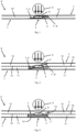
- the Figure 1 shows two single-layer floor covering elements 1, 1 ', which have only one carrier/decorative layer 10" as a single layer and are arranged side by side on the front or long side in an overlapping manner without forming an external step.
- the floor covering elements 1, 1' are also made of different Material manufactured
- the floor covering element 1 is for electromagnetic Radiation from the infrared spectral range is transparent, the floor covering element 1 'is absorbent for infrared radiation at least in the connection area 3.
- the floor covering elements 1 ' is shown hatched in the connection area 3.
- the hatching 4 is intended to illustrate the absorption capacity of the connection area 3.
- the connection area 3 is irradiated by a symbolically indicated beam 5 with electromagnetic radiation from the infrared spectral range.
- a weld seam 6 can be produced along the vertically inclined lateral edges 7, 7 'in a transmission process, which connects the two floor covering elements 1, 1' in a materially bonded and therefore sealing manner.
- the two floor covering elements 1, 1' are provided with chamfers 8, 8' in the connecting region 3, the chamfer 8 of the floor covering element 1 being designed and arranged in a complementary and mirror image to the chamfer 8' of the floor covering element 1'.
- This means that the mutually facing, directly adjacent and at least partially touching side edges 7, 7' of the two floor covering elements 1, 1' are wedge-shaped, with the bevels 8, 8' being able to be arranged one above the other in such a way that a flat floor covering 9 results.
- the Figure 2 represents two three-layer floor covering elements 1, 1', which are arranged next to each other to form a flat floor covering 9, overlapping laterally on a front side edge 7, 7' or a longitudinal side edge 7, 7'.
- the floor covering elements 1, 1' have an identical layer structure, with the layers each having different material.
- Each of the floor covering elements 1, 1' has a carrier layer 11 carrying a decorative layer 10 and an uppermost wear cover layer 12 that protects the decorative layer 10.
- At least the wear cover layer 12 is transparent for radiation from the infrared spectral range and the carrier layer 11 is absorbent for infrared radiation.
- the floor covering element 1 ' is shown hatched in the connection area 3.
- the hatching 4 is also intended to illustrate the absorption capacity of the connection area 3.
- connection area 3 is irradiated by a symbolically indicated beam 5 with electromagnetic radiation from the infrared spectral range. This allows in a radiographic process a weld seam 6 is created along the mutually facing, directly adjacent and at least partially touching side edges 7, 7', which are inclined with respect to the horizontal, and connects the two floor covering elements 1, 1' in a materially bonded and thus sealing manner.
- the two floor covering elements 1, 1' are provided with chamfers 8, 8' in the connecting region 3, the chamfer 8 of the floor covering element 1 being designed and arranged in a complementary and mirror image to the chamfer 8' of the floor covering element 1'.
- the mutually facing lateral edges 7, 7' of the two floor covering elements 1, 1' are therefore wedge-shaped, with the bevels 8, 8' being able to be arranged one above the other in such a way that a flat floor covering 9 results.
- the protruding part of the floor covering element 1, which is transparent to the (infrared) electromagnetic radiation, extends obliquely over the protruding part of the floor covering element 1' which absorbs the electromagnetic radiation.
- the Figure 3 shows two three-layer floor covering elements 1, 1 ', which are arranged next to each other to form a flat floor covering 9, overlapping laterally on a front side edge 7, 7' or a longitudinal side edge. Their layer structure is identical and as described above Figure 2 trained as described.
- the floor covering element 1 ' is shown hatched in the connection area 3, with the hatching 4 also intended to illustrate the absorption capacity of the connection area 3.
- the connection area 3 is irradiated by a symbolically indicated beam 5 with electromagnetic radiation from the infrared spectral range, so that a weld seam 6 is produced in a transmission process along the mutually facing, directly adjacent and at least partially touching side edges 7, 7 ', which the two Floor covering elements 1, 1 'cohesively and therefore sealingly connects.
- the two floor covering elements 1, 1' are provided with steps 13, 13' in the connecting area 3, the step 13 of the floor covering element 1 being designed and arranged in a complementary and mirror image to the step 13' of the floor covering element 1'.
- the mutually facing lateral edges 7, 7' of the two floor covering elements 1, 1' are thus step-shaped formed, wherein the steps 13, 13 'can be arranged one above the other in such a way that a flat floor covering 9 results.
- the protruding part of the floor covering element 1 that is transparent to the (infrared) electromagnetic radiation overlaps the protruding part of the floor covering element 1 'that absorbs the electromagnetic radiation.
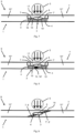
- the Figure 4 presents the two three-layer floor covering elements 1, 1 ' Figure 3 again, wherein on the floor covering element 1 and on the floor covering element 1 'in the connection area 3 plug connection means and / or click connection means 14, 14' are arranged, which are designed correspondingly and work together.
- the Figure 5 illustrates how that Figure 1 two single-layer floor covering elements 1, 1', which have a single carrier/decorative layer 10" and are arranged adjacent to one another in a connecting region 3 with front side edges or longitudinal side edges to form a flat floor covering 9.
- the floor covering elements 1, 1' have one identical single-layer layer structure, and in particular have material that is transparent to radiation.
- the two floor covering elements 1, 1 ' are provided with steps 15, 15' in the connecting area 3, the step 15 of the floor covering element 1 being identical and a mirror image of the step 15' of the Floor covering element 1 'is designed and arranged.
- the mutually facing, directly adjacent and at least partially touching side edges 7, 7' of the two floor covering elements 1, 1' are designed in a step-shaped manner, the steps 15, 15' being next to one another on an underside of the Floor covering elements 1, 1 'are arranged so that a recessed profile receiving space 16 is realized for a provided plasticizable bridging profile 17, and that a flat floor covering 9 results.
- the bridging profile 17 accommodated in the profile receiving space 16 is made of thermoplastic material that is absorbent for a certain electromagnetic radiation.
- connection area 3 is covered by a symbolically indicated beam 5 with electromagnetic radiation irradiated from the infrared spectral range, so that a weld seam 6 is produced in a transmission process along the horizontal sections of the mutually facing side edges 7, 7 'of the steps 15, 15' and the bridging profile 17, which connects the two floor covering elements 1, 1' over the bridging profile 17 sealingly connects together.
- the bridging profile 17 is shown hatched in the connection area 3, the hatching 4 being intended to illustrate the absorption capacity of the connection area 3.
- the Figure 6 again shows the two single-layer floor covering elements 1, 1 ' Figure 5 , wherein on the floor covering element 1 and on the floor covering element 1 'in the connection area 3 plug connection means and / or click connection means 14, 14' are arranged, which are designed correspondingly and work together.
- the Figure 7 illustrates how that Figure 5 two single-layer floor covering elements 1, 1 ', which are arranged adjacent to one another on front side edges or on longitudinal side edges to form a flat floor covering 9.
- the floor covering elements 1, 1' have an identical single-layer structure with a single carrier/decorative layer 10" and consist in particular of a material that is absorbent for certain electromagnetic radiation.
- the two floor covering elements 1, 1' are in the connecting area 3 with steps 15, 15', wherein the step 15 of the floor covering element 1 is designed and arranged identically and in mirror image to the step 15' of the floor covering element 1'.
- the side edges 7, 7' of the two floor covering elements 1 which face one another, are directly adjacent and at least partially touch each other , 1 'step-shaped, the steps 15, 15' being arranged side by side on an upper side of the floor covering elements 1, 1' in such a way that a recessed profile receiving space 16 for a provided plasticizable bridging profile 17 is realized on the upper side, and that a flat floor covering is formed 9 results in.
- the bridging profile 17 accommodated in the profile receiving space 16 is made of thermoplastic material, which is transparent to certain electromagnetic radiation and therefore not absorbent.
- connection area 3 is irradiated by a symbolically indicated beam 5 with electromagnetic radiation from the infrared spectral range, so that in a transmission process a weld seam 6 is formed along the horizontal sections of the mutually facing side edges 7, 7 ', the steps 15, 15' and the bridging profile 17 is generated, which sealingly connects the two floor covering elements 1, 1 'to one another via the bridging profile 17.
- the bridging profile 17 is shown hatched in the connection area 3, with the hatching 4 intended to illustrate the absorption capacity of the connection area.
- the Figure 8 again shows the two single-layer floor covering elements 1, 1 ' Figure 7 , wherein on the floor covering element 1 and on the floor covering element 1 'in the connection area 3 plug connection means and / or click connection means 14, 14' are arranged, which are designed correspondingly and work together.
- the Figure 9 poses like that Figure 1 two single-layer floor covering elements 1, 1 ', which are arranged adjacent to one another and overlapping without forming an external step on front side edges or longitudinal side edges.
- the floor covering elements 1, 1 ' are made from identical materials. They have a single carrier/decorative layer 10" which is transparent to electromagnetic radiation from the infrared spectral range.
- the two floor covering elements 1, 1' are provided with chamfers 8, 8' in the connecting region 3, the chamfer 8 of the floor covering element 1 being complementary and is designed and arranged in mirror image to the bevel 8 'of the floor covering element 1'.
- the mutually facing, directly adjacent and at least partially touching side edges 7, 7' of the two floor covering elements 1, 1' are thus wedge-shaped, with the bevels 8, 8 'are arranged one above the other in such a way that a flat floor covering 9 results.
- the side edges 7, 7' are provided in the connection area 3 with a coating 18 that absorbs electromagnetic radiation from the infrared spectral range, which is shown hatched in the connection area 3 to emphasize its absorption capacity.
- the connection area 3 is irradiated with infrared electromagnetic radiation by a symbolically indicated beam 5.
- a weld seam 6 can be produced in a transmission process along the oblique, mutually facing lateral edges 7, 7 ', which connects the two floor covering elements 1, 1' in a materially bonded and therefore sealing manner.
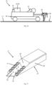
- the Figure 10 shows a sealing/connecting device 19 according to the invention for sealing/connecting mutually facing, directly adjacent and at least partially touching side edges 7, 7' of at least two web- or plate-shaped adjacent single-layer or multi-layer floor covering elements 1, 1' made of plastic material.
- the sealing/connecting device 19 has a chassis 20 for moving on a floor covering 9, means 21 for introducing energy into a connection area 3 along the lateral edges 7, 7 'in an area surrounding the edges 7, 7' of the floor covering elements 1, 1' Drive 22 for independently moving the device 19 on the floor covering 9, control means 23 for controlling the movement of the device 19 on the floor covering 9 and at least one sensor 24 for directly or indirectly detecting the position of the chassis 20 on the floor covering 9, a sensor 25 for Detecting the temperature of the floor covering elements 1, 1 'at least in a connection area 3 and / or control means 26 for setting/controlling the temperature at least in a connection area 3.
- a cutting tool 2 is shown as an example in an isometric view.
- the cutting tool 2 includes a cuboid base body 27 with four elongated, rectangular side surfaces and two square end surfaces.
- the base body 27 is made of metal in the exemplary embodiment shown.
- the cuboid base body 27 is modified in such a way that two opposite elongated side surfaces - one of these side surfaces is in Figure 11 marked with the reference number 28 - beveled in a triangular shape towards one of the square end faces of the cuboid base body 27 be that this end face is reduced to a narrow edge 32.
- the unmodified elongated side surface on the underside and part of the elongated, modified side surface on the top of the base body converge at an acute angle. In the exemplary embodiment shown here, this angle is 20°.
- the part of the top, elongated, modified side surface that converges on the edge 32 with the elongated side surface on the underside of the base body 27 is referred to as the wedge surface 29.
- a commercially available trapezoidal blade 30 (known from carpet or cutter knives) is arranged lying on the wedge surface 29 and is releasably fixed on both sides by four screws 31 placed equidistant from one another along the two side edges of the wedge surface 29.
- the base body 27 is provided with eight corresponding threaded holes for receiving the screws 31.
- the trapezoidal blade 30 can therefore be easily replaced if this is necessary due to wear.
- the trapezoidal blade 30 is arranged parallel to the side edges of the wedge surface 29 and extends a little way beyond the base body 27 in the area of the edge 32, at which the underside elongated side surface and the wedge surface 29 converge, in order to ensure a free cutting area.
Landscapes
- Engineering & Computer Science (AREA)
- Mechanical Engineering (AREA)
- Physics & Mathematics (AREA)
- Forests & Forestry (AREA)
- Electromagnetism (AREA)
- Life Sciences & Earth Sciences (AREA)
- Health & Medical Sciences (AREA)
- Thermal Sciences (AREA)
- Architecture (AREA)
- Toxicology (AREA)
- Structural Engineering (AREA)
- Civil Engineering (AREA)
- Floor Finish (AREA)
Claims (11)
- Procédé d'étanchéification/de liaison d'au moins deux éléments de revêtement de sol (1, 1') plats, adjacents l'un à l'autre, en matière plastique, l'un avec l'autre le long de leurs bords latéraux (7, 7') tournés l'un vers l'autre, directement voisins et se touchant au moins partiellement, les éléments de revêtement de sol étant agencés à plat sur un sol dans une pièce d'un bâtiment, caractérisé en ce qu'on utilise en tant qu'éléments de revêtement de sol (1, 1') des éléments de revêtement de sol (1, 1') monocouches ou multicouches qui se chevauchent dans une zone de leurs bords latéraux (7, 7') de telle sorte qu'un élément de revêtement de sol (1, 1') recouvre un autre élément de revêtement de sol (1', 1) à sa surface uniquement avec une partie de son épaisseur de matériau totale, la température d'au moins l'un des éléments de revêtement de sol (1) adjacents l'un à l'autre étant temporairement augmentée localement par rapport à la température ambiante le long de ses bords latéraux (7) adjacents aux bords latéraux (7') d'un autre élément de revêtement de sol (1') dans un environnement de ses bords (7) par apport d'énergie dans une mesure telle qu'au moins une couche des éléments de revêtement de sol (1, 1') est au moins partiellement plastifiée localement dans une zone de liaison (3) le long de leurs bords latéraux (7, 7') directement voisins et se touchant au moins partiellement dans un environnement des bords (7, 7'), moyennant quoi l'un des éléments de revêtement de sol (1) est relié à l'autre élément de revêtement de sol (1') par liaison de matière, un rayonnement électromagnétique de la plage spectrale infrarouge étant utilisé pour l'augmentation locale de la température, et la surface totale commune des éléments de revêtement de sol (1, 1') ne présentant pas d'arêtes, de gradins et/ou de fentes à la fin du procédé d'étanchéification/de liaison, notamment dans la zone de liaison (3).
- Procédé d'étanchéification/de liaison selon la revendication 1, caractérisé en ce qu'on utilise en tant qu'éléments de revêtement de sol (1, 1') des éléments de revêtement de sol (1, 1') multicouches avec au moins une couche de support (11) portant une couche décorative ainsi qu'une couche de couverture d'usure supérieure (12) protégeant la couche décorative (10), la température d'au moins l'un des éléments de revêtement de sol (1) adjacents l'un à l'autre étant temporairement augmentée localement par rapport à la température ambiante le long de ses bords latéraux (7) adjacents aux bords latéraux (7') d'un autre élément de revêtement de sol (1') dans un environnement de ses bords (7) par apport d'énergie dans une mesure telle qu'au moins une couche (10, 11, 12) des éléments de revêtement de sol (1, 1') est au moins partiellement plastifiée localement dans une zone de liaison (3) le long de leurs bords latéraux (7, 7') directement voisins et se touchant au moins partiellement dans un environnement des bords latéraux (7, 7'), l'un des éléments de revêtement de sol (1) étant relié directement ou indirectement à l'autre élément de revêtement de sol (1') par liaison de matière.
- Procédé d'étanchéification/de liaison selon la revendication 1, caractérisé en ce qu'on utilise en tant qu'éléments de revêtement de sol (1, 1') des éléments de revêtement de sol (1, 1') monocouches, la température d'au moins l'un des éléments de revêtement de sol (1) adjacents l'un à l'autre étant temporairement augmentée localement par rapport à la température ambiante dans un environnement le long de ses bords latéraux (7) adjacents aux bords latéraux (7') d'un autre élément de revêtement de sol (1') par apport d'énergie directement ou indirectement dans une mesure telle que la couche des éléments de revêtement de sol (1, 1') est au moins partiellement plastifiée le long de leurs bords latéraux (7, 7') directement voisins et se touchant au moins partiellement dans un environnement des bords latéraux (7, 7'), l'un des éléments de revêtement de sol (1) étant directement relié à l'autre élément de revêtement de sol (1') par liaison de matière.
- Procédé d'étanchéification/de liaison selon la revendication 2, caractérisé en ce qu'au moins l'un de deux éléments de revêtement de sol (1) adjacents l'un à l'autre présente, le long de ses bords latéraux (7) adjacents aux bords latéraux d'un autre élément de revêtement de sol (1'), au moins dans une zone de liaison (3), dans un environnement de ses bords (7), au moins une couche supérieure, transparente dans la plage spectrale infrarouge, en tant que couche de couverture d'usure (12) et au moins une couche inférieure, absorbant dans la plage spectrale infrarouge, en tant que couche de support (11), et en ce que les bords latéraux (7, 7') directement voisins et se touchant au moins partiellement des éléments de revêtement de sol (1, 1') sont formés ou post-formés dans la zone de liaison (3) le long des bords latéraux (7, 7') dans un environnement des bords (7, 7') de telle sorte, que lors de l'assemblage des éléments de revêtement de sol (1, 1') en un revêtement de sol (9), la couche transparente de l'un des éléments de revêtement de sol (1) est agencée de manière à recouvrir directement la couche absorbante de l'autre élément de revêtement de sol (1') et est reliée à celle-ci par liaison de matière.
- Procédé d'étanchéification/de liaison selon la revendication 2 ou 3, caractérisé en ce que les bords latéraux (7, 7') directement voisins et se touchant au moins partiellement des éléments de revêtement de sol (1, 1') sont pourvus d'un chanfrein (8), d'un gradin (13, 15, 16) ou d'une rainure dans la zone de liaison (3) le long de leurs bords latéraux (7, 7') dans un environnement des bords latéraux (7, 7').
- Procédé d'étanchéification/de liaison selon l'une quelconque des revendications 2 à 5 précédentes, caractérisé en ce que les bords latéraux (7, 7') directement voisins et se touchant au moins partiellement des éléments de revêtement de sol (1, 1') sont pourvus d'un revêtement (18) transparent ou absorbant dans la plage spectrale infrarouge dans la zone de liaison (3) le long de leurs bords latéraux (7, 7') dans un environnement des bords latéraux (7, 7').
- Procédé d'étanchéification/de liaison selon l'une quelconque des revendications 1 à 6 précédentes, caractérisé en ce que, lors de la fabrication des éléments de revêtement de sol (1, 1'), des moyens de liaison par emboîtement (14, 14') ou des moyens de liaison par encliquetage (14, 14') sont réalisés le long des bords latéraux (7, 7') au moins sur un côté longitudinal et/ou au moins sur un côté de tête des éléments de revêtement de sol (1, 1') ; lors de l'assemblage des éléments de revêtement de sol (1, 1') en un revêtement de sol (9), les moyens de liaison par emboîtement(14, 14') étant amenés en engagement mutuel par glissement et les moyens de liaison par encliquetage (14, 14') par enclenchement.
- Dispositif d'étanchéification/de liaison pour la mise en oeuvre du procédé selon l'une quelconque des revendications 1 à 7 précédentes, comprenant un châssis (20) destiné à se déplacer sur un revêtement de sol (9), des moyens (21) pour l'apport d'énergie au moyen d'un rayonnement électromagnétique de la plage proche infrarouge dans une zone de liaison (3) le long des bords latéraux (7, 7') dans un environnement des bords latéraux (7, 7') des éléments de revêtement de sol (1, 1'), un entraînement (22) pour déplacer de manière autonome le dispositif (19) sur le revêtement de sol (9), des moyens de commande (23) pour commander le déplacement du dispositif (19) sur le revêtement de sol (9) et au moins un capteur (24) pour détecter directement ou indirectement la position du châssis (20) sur le revêtement de sol (9), un capteur (25) pour détecter la température des éléments de revêtement de sol (1, 1') au moins dans une zone de liaison (3) et/ou des moyens de régulation (26) pour ajuster/réguler la température au moins dans une zone de liaison (3), caractérisé par une réalisation des moyens pour l'apport d'énergie (21) sous forme de projecteurs halogènes.
- Élément de revêtement de sol (1, 1') multicouche, plat et présentant une matière plastique thermoplastique, destiné à être assemblé en un revêtement de sol (9) sur un sol d'une pièce d'un bâtiment, caractérisé en ce que deux éléments de revêtement de sol (1, 1') adjacents l'un à l'autre se chevauchent dans une zone de leurs bords latéraux (7, 7') de telle sorte que l'un des éléments de revêtement de sol (1, 1') recouvre l'autre élément de revêtement de sol (1, 1') à sa surface uniquement avec une partie de son épaisseur de matériau totale, et en ce que l'élément de revêtement de sol (1, 1') est réalisé pour mettre en oeuvre le procédé d'étanchéification/de liaison selon l'une quelconque des revendications 1 à 7 précédentes.
- Élément de revêtement de sol multicouche (1, 1') selon la revendication 9, caractérisé par au moins une couche de support (11) portant une couche décorative (10), une couche de couverture d'usure supérieure (12) protégeant la couche décorative (11), au moins dans une zone de liaison (3) le long de ses bords latéraux (7, 7') dans un environnement des bords latéraux (7, 7') au moins une couche supérieure (10, 11, 12) transparente dans la plage spectrale infrarouge et au moins une couche inférieure (10, 11, 12) absorbant dans la plage spectrale infrarouge, au moins l'une des couches (10, 11, 12) de l'élément de revêtement de sol (1, 1') pouvant être au moins partiellement plastifiée localement dans une zone de liaison (3) de l'élément de revêtement de sol (1, 1') directement et/ou indirectement par apport d'énergie, et les bords latéraux (7, 7') de l'élément de revêtement de sol (1, 1') étant formés ou post-formés le long des bords latéraux (7, 7') au moins dans la zone de liaison (3) de telle sorte que lors de l'assemblage des éléments de revêtement de sol (1, 1') en un revêtement de sol (9), la couche transparente (10, 11, 12) d'un élément de revêtement de sol (1, 1') peut être agencée de manière à recouvrir directement la couche absorbante (10, 11, 12) d'un élément de revêtement de sol (1' 1) voisin et peut être reliée à celle-ci par liaison de matière.
- Élément de revêtement de sol (1, 1') monocouche, plat et présentant une matière plastique thermoplastique, destiné à être assemblé en un revêtement de sol (9) sur un sol d'une pièce d'un bâtiment, caractérisé en ce que deux éléments de revêtement de sol (1, 1') adjacents l'un à l'autre se chevauchent dans une zone de leurs bords latéraux (7, 7') de telle sorte que l'un des éléments de revêtement de sol (1, 1') recouvre l'autre élément de revêtement de sol (1, 1') à sa surface uniquement avec une partie de son épaisseur de matériau totale, la couche (10") de l'élément de revêtement de sol (1, 1') peut être au moins partiellement plastifiée localement dans une zone de liaison (3) le long de ses bords latéraux (7, 7') dans un environnement de ses bords latéraux (7, 7') directement et/ou indirectement par apport d'énergie, les bords latéraux (7, 7') de l'élément de revêtement de sol (1, 1') étant formés ou post-formés dans la zone de liaison (3) de telle sorte que, lors de l'assemblage des éléments de revêtement de sol (1, 1') en un revêtement de sol (9), la couche (10") d'un élément de revêtement de sol (1, 1') peut être agencée de manière à recouvrir directement la couche (10") d'un élément de revêtement de sol (1', 1) voisin et peut être reliée par liaison de matière, et l'élément de revêtement de sol (1, 1') est réalisé pour la mise en oeuvre du procédé d'étanchéification/de liaison selon l'une des revendications 1 à 7 précédentes.
Applications Claiming Priority (1)
| Application Number | Priority Date | Filing Date | Title |
|---|---|---|---|
| EP17181902 | 2017-07-18 |
Publications (3)
| Publication Number | Publication Date |
|---|---|
| EP3431265A2 EP3431265A2 (fr) | 2019-01-23 |
| EP3431265A3 EP3431265A3 (fr) | 2019-04-17 |
| EP3431265B1 true EP3431265B1 (fr) | 2024-02-14 |
Family
ID=59381127
Family Applications (1)
| Application Number | Title | Priority Date | Filing Date |
|---|---|---|---|
| EP18183337.7A Active EP3431265B1 (fr) | 2017-07-18 | 2018-07-13 | Procédé d'étanchéification et de raccordement ainsi que dispositif d'étanchéification et de raccordement pour arêtes de bord d'éléments de revêtement de sol en matière plastique |
Country Status (1)
| Country | Link |
|---|---|
| EP (1) | EP3431265B1 (fr) |
Families Citing this family (1)
| Publication number | Priority date | Publication date | Assignee | Title |
|---|---|---|---|---|
| CN112709412A (zh) * | 2020-12-24 | 2021-04-27 | 华睿企业管理咨询(衢州)有限公司 | 一种木塑地板生产用拼接成型设备 |
Family Cites Families (6)
| Publication number | Priority date | Publication date | Assignee | Title |
|---|---|---|---|---|
| US4913772A (en) * | 1988-04-01 | 1990-04-03 | G.R. Systems, Inc. | Portable thermoplastic welding machine |
| DE19532598A1 (de) | 1995-09-04 | 1997-03-06 | Dlw Ag | Thermoplastischer Kunststoffdraht und Verfahren zu dessen Herstellung |
| DE10048000B4 (de) * | 1999-09-26 | 2004-04-22 | Bernd Kempkens | Vorrichtungen, Verfahren und Systemelemente zum Verschweißen und/oder Abdichten von Bodenbelägen |
| DE10359909B4 (de) * | 2003-12-18 | 2014-09-18 | Plasticon Germany Gmbh | Schweißvorrichtung |
| DE102008029007A1 (de) * | 2008-06-20 | 2009-12-24 | Plasticon Germany Gmbh | Handschweißgerät |
| FR2957841B1 (fr) * | 2010-03-24 | 2012-07-06 | Plasticell | Appareil de soudage de membranes thermoplastiques |
-
2018
- 2018-07-13 EP EP18183337.7A patent/EP3431265B1/fr active Active
Also Published As
| Publication number | Publication date |
|---|---|
| EP3431265A3 (fr) | 2019-04-17 |
| EP3431265A2 (fr) | 2019-01-23 |
Similar Documents
| Publication | Publication Date | Title |
|---|---|---|
| EP2586929B1 (fr) | Revêtement de sol | |
| DE202010018550U1 (de) | Paneel | |
| EP2163708B1 (fr) | Profil doté d'un corps profilé fabriqué à partir d'un matériau composite de plastique et de bois en forme de faisceau, par exemple dans le sens de l'extrusion | |
| WO2010006684A2 (fr) | Procédé d'application de panneaux de sol | |
| EP1362947A2 (fr) | Dalle de moquette | |
| EP2955296B1 (fr) | Procédé de fabrication d'un panneau et panneau | |
| EP1593795B1 (fr) | Procédé et appareillage pour fabriquer des éléments plans, en particulier des éléments de plancher | |
| DE102004023158A1 (de) | Flächiges Element sowie Verfahren zur Bildung von seitlichen Verbindungsmitteln an miteinander verbindbaren flächigen Elementen | |
| WO2017202486A1 (fr) | Éléments pour former des revêtements et leurs moyens d'assemblage | |
| EP3431265A2 (fr) | Procédé d'étanchéification et de raccordement ainsi que dispositif d'étanchéification et de raccordement pour arêtes de bord d'éléments de revêtement de sol en matière plastique | |
| EP1683929B1 (fr) | Procédé de fabrication d'un panneau, notamment d'un panneau de plancher, et panneau, notamment panneau de plancher | |
| EP2017402A2 (fr) | Panneau de sol | |
| DE202011107236U1 (de) | Fußbodenbelag | |
| DE202012011049U1 (de) | Vorrichtung zum Auftragen und Verteilen einer pastösen Masse | |
| DE10033495C2 (de) | Kork-Flächenverkleidung, insbesondere Kork-Bodenbelag, und Verfahren zu deren Herstellung | |
| DE19941284A1 (de) | Belagsystem sowie Verfahren zur Verlegung desselben | |
| EP2995929A2 (fr) | Chambre de test de climatisation | |
| EP1012425B1 (fr) | Plancher avec revetement de sol et procede pour la pose de ce revetement de sol | |
| DE10302961B4 (de) | Wandabschlussleiste | |
| DE4016288C2 (de) | Verfahren zum Herstellen einer polygonalen Verbundplatte für Fußböden und durch das Verfahren hergestellte Verbundplatte | |
| EP3601694B1 (fr) | Éléments de construction en bois activés et procédé de fabrication de tels éléments de construction | |
| DE102007036267A1 (de) | Flächenelastischer Boden und zugehörige Fußbodenplatte | |
| DE102011002149B4 (de) | Verfahren zur Herstellung von Paneelen | |
| AT517773A2 (de) | Wandverkleidungsplatte | |
| DE10112958B4 (de) | Fussbodenpaneel |
Legal Events
| Date | Code | Title | Description |
|---|---|---|---|
| PUAI | Public reference made under article 153(3) epc to a published international application that has entered the european phase |
Free format text: ORIGINAL CODE: 0009012 |
|
| STAA | Information on the status of an ep patent application or granted ep patent |
Free format text: STATUS: THE APPLICATION HAS BEEN PUBLISHED |
|
| AK | Designated contracting states |
Kind code of ref document: A2 Designated state(s): AL AT BE BG CH CY CZ DE DK EE ES FI FR GB GR HR HU IE IS IT LI LT LU LV MC MK MT NL NO PL PT RO RS SE SI SK SM TR |
|
| AX | Request for extension of the european patent |
Extension state: BA ME |
|
| PUAL | Search report despatched |
Free format text: ORIGINAL CODE: 0009013 |
|
| STAA | Information on the status of an ep patent application or granted ep patent |
Free format text: STATUS: REQUEST FOR EXAMINATION WAS MADE |
|
| AK | Designated contracting states |
Kind code of ref document: A3 Designated state(s): AL AT BE BG CH CY CZ DE DK EE ES FI FR GB GR HR HU IE IS IT LI LT LU LV MC MK MT NL NO PL PT RO RS SE SI SK SM TR |
|
| AX | Request for extension of the european patent |
Extension state: BA ME |
|
| RIC1 | Information provided on ipc code assigned before grant |
Ipc: B29L 9/00 20060101ALN20190313BHEP Ipc: B26D 3/02 20060101ALI20190313BHEP Ipc: B29K 101/12 20060101ALN20190313BHEP Ipc: B29C 65/14 20060101AFI20190313BHEP Ipc: E04F 21/20 20060101ALI20190313BHEP Ipc: B26B 5/00 20060101ALI20190313BHEP Ipc: B26D 7/26 20060101ALI20190313BHEP |
|
| 17P | Request for examination filed |
Effective date: 20190329 |
|
| RBV | Designated contracting states (corrected) |
Designated state(s): AL AT BE BG CH CY CZ DE DK EE ES FI FR GB GR HR HU IE IS IT LI LT LU LV MC MK MT NL NO PL PT RO RS SE SI SK SM TR |
|
| STAA | Information on the status of an ep patent application or granted ep patent |
Free format text: STATUS: EXAMINATION IS IN PROGRESS |
|
| 17Q | First examination report despatched |
Effective date: 20210520 |
|
| GRAP | Despatch of communication of intention to grant a patent |
Free format text: ORIGINAL CODE: EPIDOSNIGR1 |
|
| STAA | Information on the status of an ep patent application or granted ep patent |
Free format text: STATUS: GRANT OF PATENT IS INTENDED |
|
| RIC1 | Information provided on ipc code assigned before grant |
Ipc: B29L 9/00 20060101ALN20230825BHEP Ipc: B29K 101/12 20060101ALN20230825BHEP Ipc: B26B 5/00 20060101ALI20230825BHEP Ipc: B26D 7/26 20060101ALI20230825BHEP Ipc: B26D 3/02 20060101ALI20230825BHEP Ipc: E04F 21/20 20060101ALI20230825BHEP Ipc: B29C 65/14 20060101AFI20230825BHEP |
|
| INTG | Intention to grant announced |
Effective date: 20230913 |
|
| P01 | Opt-out of the competence of the unified patent court (upc) registered |
Effective date: 20231128 |
|
| GRAS | Grant fee paid |
Free format text: ORIGINAL CODE: EPIDOSNIGR3 |
|
| GRAA | (expected) grant |
Free format text: ORIGINAL CODE: 0009210 |
|
| STAA | Information on the status of an ep patent application or granted ep patent |
Free format text: STATUS: THE PATENT HAS BEEN GRANTED |
|
| AK | Designated contracting states |
Kind code of ref document: B1 Designated state(s): AL AT BE BG CH CY CZ DE DK EE ES FI FR GB GR HR HU IE IS IT LI LT LU LV MC MK MT NL NO PL PT RO RS SE SI SK SM TR |
|
| REG | Reference to a national code |
Ref country code: GB Ref legal event code: FG4D Free format text: NOT ENGLISH |
|
| REG | Reference to a national code |
Ref country code: CH Ref legal event code: EP |
|
| REG | Reference to a national code |
Ref country code: DE Ref legal event code: R096 Ref document number: 502018014096 Country of ref document: DE |
|
| REG | Reference to a national code |
Ref country code: IE Ref legal event code: FG4D Free format text: LANGUAGE OF EP DOCUMENT: GERMAN |
|
| REG | Reference to a national code |
Ref country code: LT Ref legal event code: MG9D |
|
| REG | Reference to a national code |
Ref country code: NL Ref legal event code: MP Effective date: 20240214 |
|
| PG25 | Lapsed in a contracting state [announced via postgrant information from national office to epo] |
Ref country code: IS Free format text: LAPSE BECAUSE OF FAILURE TO SUBMIT A TRANSLATION OF THE DESCRIPTION OR TO PAY THE FEE WITHIN THE PRESCRIBED TIME-LIMIT Effective date: 20240614 |
|
| PG25 | Lapsed in a contracting state [announced via postgrant information from national office to epo] |
Ref country code: LT Free format text: LAPSE BECAUSE OF FAILURE TO SUBMIT A TRANSLATION OF THE DESCRIPTION OR TO PAY THE FEE WITHIN THE PRESCRIBED TIME-LIMIT Effective date: 20240214 |
|
| PG25 | Lapsed in a contracting state [announced via postgrant information from national office to epo] |
Ref country code: GR Free format text: LAPSE BECAUSE OF FAILURE TO SUBMIT A TRANSLATION OF THE DESCRIPTION OR TO PAY THE FEE WITHIN THE PRESCRIBED TIME-LIMIT Effective date: 20240515 |
|
| PG25 | Lapsed in a contracting state [announced via postgrant information from national office to epo] |
Ref country code: HR Free format text: LAPSE BECAUSE OF FAILURE TO SUBMIT A TRANSLATION OF THE DESCRIPTION OR TO PAY THE FEE WITHIN THE PRESCRIBED TIME-LIMIT Effective date: 20240214 Ref country code: NL Free format text: LAPSE BECAUSE OF FAILURE TO SUBMIT A TRANSLATION OF THE DESCRIPTION OR TO PAY THE FEE WITHIN THE PRESCRIBED TIME-LIMIT Effective date: 20240214 Ref country code: RS Free format text: LAPSE BECAUSE OF FAILURE TO SUBMIT A TRANSLATION OF THE DESCRIPTION OR TO PAY THE FEE WITHIN THE PRESCRIBED TIME-LIMIT Effective date: 20240514 |
|
| PG25 | Lapsed in a contracting state [announced via postgrant information from national office to epo] |
Ref country code: ES Free format text: LAPSE BECAUSE OF FAILURE TO SUBMIT A TRANSLATION OF THE DESCRIPTION OR TO PAY THE FEE WITHIN THE PRESCRIBED TIME-LIMIT Effective date: 20240214 |
|
| PG25 | Lapsed in a contracting state [announced via postgrant information from national office to epo] |
Ref country code: RS Free format text: LAPSE BECAUSE OF FAILURE TO SUBMIT A TRANSLATION OF THE DESCRIPTION OR TO PAY THE FEE WITHIN THE PRESCRIBED TIME-LIMIT Effective date: 20240514 Ref country code: NO Free format text: LAPSE BECAUSE OF FAILURE TO SUBMIT A TRANSLATION OF THE DESCRIPTION OR TO PAY THE FEE WITHIN THE PRESCRIBED TIME-LIMIT Effective date: 20240514 Ref country code: NL Free format text: LAPSE BECAUSE OF FAILURE TO SUBMIT A TRANSLATION OF THE DESCRIPTION OR TO PAY THE FEE WITHIN THE PRESCRIBED TIME-LIMIT Effective date: 20240214 Ref country code: LT Free format text: LAPSE BECAUSE OF FAILURE TO SUBMIT A TRANSLATION OF THE DESCRIPTION OR TO PAY THE FEE WITHIN THE PRESCRIBED TIME-LIMIT Effective date: 20240214 Ref country code: IS Free format text: LAPSE BECAUSE OF FAILURE TO SUBMIT A TRANSLATION OF THE DESCRIPTION OR TO PAY THE FEE WITHIN THE PRESCRIBED TIME-LIMIT Effective date: 20240614 Ref country code: HR Free format text: LAPSE BECAUSE OF FAILURE TO SUBMIT A TRANSLATION OF THE DESCRIPTION OR TO PAY THE FEE WITHIN THE PRESCRIBED TIME-LIMIT Effective date: 20240214 Ref country code: GR Free format text: LAPSE BECAUSE OF FAILURE TO SUBMIT A TRANSLATION OF THE DESCRIPTION OR TO PAY THE FEE WITHIN THE PRESCRIBED TIME-LIMIT Effective date: 20240515 Ref country code: FI Free format text: LAPSE BECAUSE OF FAILURE TO SUBMIT A TRANSLATION OF THE DESCRIPTION OR TO PAY THE FEE WITHIN THE PRESCRIBED TIME-LIMIT Effective date: 20240214 Ref country code: ES Free format text: LAPSE BECAUSE OF FAILURE TO SUBMIT A TRANSLATION OF THE DESCRIPTION OR TO PAY THE FEE WITHIN THE PRESCRIBED TIME-LIMIT Effective date: 20240214 Ref country code: BG Free format text: LAPSE BECAUSE OF FAILURE TO SUBMIT A TRANSLATION OF THE DESCRIPTION OR TO PAY THE FEE WITHIN THE PRESCRIBED TIME-LIMIT Effective date: 20240214 |
|
| PG25 | Lapsed in a contracting state [announced via postgrant information from national office to epo] |
Ref country code: PL Free format text: LAPSE BECAUSE OF FAILURE TO SUBMIT A TRANSLATION OF THE DESCRIPTION OR TO PAY THE FEE WITHIN THE PRESCRIBED TIME-LIMIT Effective date: 20240214 Ref country code: PT Free format text: LAPSE BECAUSE OF FAILURE TO SUBMIT A TRANSLATION OF THE DESCRIPTION OR TO PAY THE FEE WITHIN THE PRESCRIBED TIME-LIMIT Effective date: 20240614 |
|
| PG25 | Lapsed in a contracting state [announced via postgrant information from national office to epo] |
Ref country code: SE Free format text: LAPSE BECAUSE OF FAILURE TO SUBMIT A TRANSLATION OF THE DESCRIPTION OR TO PAY THE FEE WITHIN THE PRESCRIBED TIME-LIMIT Effective date: 20240214 Ref country code: PT Free format text: LAPSE BECAUSE OF FAILURE TO SUBMIT A TRANSLATION OF THE DESCRIPTION OR TO PAY THE FEE WITHIN THE PRESCRIBED TIME-LIMIT Effective date: 20240614 Ref country code: PL Free format text: LAPSE BECAUSE OF FAILURE TO SUBMIT A TRANSLATION OF THE DESCRIPTION OR TO PAY THE FEE WITHIN THE PRESCRIBED TIME-LIMIT Effective date: 20240214 Ref country code: LV Free format text: LAPSE BECAUSE OF FAILURE TO SUBMIT A TRANSLATION OF THE DESCRIPTION OR TO PAY THE FEE WITHIN THE PRESCRIBED TIME-LIMIT Effective date: 20240214 |
|
| PG25 | Lapsed in a contracting state [announced via postgrant information from national office to epo] |
Ref country code: DK Free format text: LAPSE BECAUSE OF FAILURE TO SUBMIT A TRANSLATION OF THE DESCRIPTION OR TO PAY THE FEE WITHIN THE PRESCRIBED TIME-LIMIT Effective date: 20240214 |
|
| PG25 | Lapsed in a contracting state [announced via postgrant information from national office to epo] |
Ref country code: SM Free format text: LAPSE BECAUSE OF FAILURE TO SUBMIT A TRANSLATION OF THE DESCRIPTION OR TO PAY THE FEE WITHIN THE PRESCRIBED TIME-LIMIT Effective date: 20240214 |
|
| PG25 | Lapsed in a contracting state [announced via postgrant information from national office to epo] |
Ref country code: CZ Free format text: LAPSE BECAUSE OF FAILURE TO SUBMIT A TRANSLATION OF THE DESCRIPTION OR TO PAY THE FEE WITHIN THE PRESCRIBED TIME-LIMIT Effective date: 20240214 Ref country code: EE Free format text: LAPSE BECAUSE OF FAILURE TO SUBMIT A TRANSLATION OF THE DESCRIPTION OR TO PAY THE FEE WITHIN THE PRESCRIBED TIME-LIMIT Effective date: 20240214 |
|
| PG25 | Lapsed in a contracting state [announced via postgrant information from national office to epo] |
Ref country code: SK Free format text: LAPSE BECAUSE OF FAILURE TO SUBMIT A TRANSLATION OF THE DESCRIPTION OR TO PAY THE FEE WITHIN THE PRESCRIBED TIME-LIMIT Effective date: 20240214 |
|
| PG25 | Lapsed in a contracting state [announced via postgrant information from national office to epo] |
Ref country code: SM Free format text: LAPSE BECAUSE OF FAILURE TO SUBMIT A TRANSLATION OF THE DESCRIPTION OR TO PAY THE FEE WITHIN THE PRESCRIBED TIME-LIMIT Effective date: 20240214 Ref country code: SK Free format text: LAPSE BECAUSE OF FAILURE TO SUBMIT A TRANSLATION OF THE DESCRIPTION OR TO PAY THE FEE WITHIN THE PRESCRIBED TIME-LIMIT Effective date: 20240214 Ref country code: RO Free format text: LAPSE BECAUSE OF FAILURE TO SUBMIT A TRANSLATION OF THE DESCRIPTION OR TO PAY THE FEE WITHIN THE PRESCRIBED TIME-LIMIT Effective date: 20240214 Ref country code: EE Free format text: LAPSE BECAUSE OF FAILURE TO SUBMIT A TRANSLATION OF THE DESCRIPTION OR TO PAY THE FEE WITHIN THE PRESCRIBED TIME-LIMIT Effective date: 20240214 Ref country code: DK Free format text: LAPSE BECAUSE OF FAILURE TO SUBMIT A TRANSLATION OF THE DESCRIPTION OR TO PAY THE FEE WITHIN THE PRESCRIBED TIME-LIMIT Effective date: 20240214 Ref country code: CZ Free format text: LAPSE BECAUSE OF FAILURE TO SUBMIT A TRANSLATION OF THE DESCRIPTION OR TO PAY THE FEE WITHIN THE PRESCRIBED TIME-LIMIT Effective date: 20240214 |
|
| REG | Reference to a national code |
Ref country code: DE Ref legal event code: R097 Ref document number: 502018014096 Country of ref document: DE |
|
| PG25 | Lapsed in a contracting state [announced via postgrant information from national office to epo] |
Ref country code: IT Free format text: LAPSE BECAUSE OF FAILURE TO SUBMIT A TRANSLATION OF THE DESCRIPTION OR TO PAY THE FEE WITHIN THE PRESCRIBED TIME-LIMIT Effective date: 20240214 |
|
| PLBE | No opposition filed within time limit |
Free format text: ORIGINAL CODE: 0009261 |
|
| STAA | Information on the status of an ep patent application or granted ep patent |
Free format text: STATUS: NO OPPOSITION FILED WITHIN TIME LIMIT |
|
| PG25 | Lapsed in a contracting state [announced via postgrant information from national office to epo] |
Ref country code: IT Free format text: LAPSE BECAUSE OF FAILURE TO SUBMIT A TRANSLATION OF THE DESCRIPTION OR TO PAY THE FEE WITHIN THE PRESCRIBED TIME-LIMIT Effective date: 20240214 |
|
| 26N | No opposition filed |
Effective date: 20241115 |
|
| PG25 | Lapsed in a contracting state [announced via postgrant information from national office to epo] |
Ref country code: MC Free format text: LAPSE BECAUSE OF FAILURE TO SUBMIT A TRANSLATION OF THE DESCRIPTION OR TO PAY THE FEE WITHIN THE PRESCRIBED TIME-LIMIT Effective date: 20240214 |
|
| REG | Reference to a national code |
Ref country code: CH Ref legal event code: PL |
|
| PG25 | Lapsed in a contracting state [announced via postgrant information from national office to epo] |
Ref country code: LU Free format text: LAPSE BECAUSE OF NON-PAYMENT OF DUE FEES Effective date: 20240713 |
|
| GBPC | Gb: european patent ceased through non-payment of renewal fee |
Effective date: 20240713 |
|
| PG25 | Lapsed in a contracting state [announced via postgrant information from national office to epo] |
Ref country code: LU Free format text: LAPSE BECAUSE OF NON-PAYMENT OF DUE FEES Effective date: 20240713 |
|
| PG25 | Lapsed in a contracting state [announced via postgrant information from national office to epo] |
Ref country code: BE Free format text: LAPSE BECAUSE OF NON-PAYMENT OF DUE FEES Effective date: 20240731 Ref country code: SI Free format text: LAPSE BECAUSE OF FAILURE TO SUBMIT A TRANSLATION OF THE DESCRIPTION OR TO PAY THE FEE WITHIN THE PRESCRIBED TIME-LIMIT Effective date: 20240214 Ref country code: CH Free format text: LAPSE BECAUSE OF NON-PAYMENT OF DUE FEES Effective date: 20240731 |
|
| PG25 | Lapsed in a contracting state [announced via postgrant information from national office to epo] |
Ref country code: FR Free format text: LAPSE BECAUSE OF NON-PAYMENT OF DUE FEES Effective date: 20240731 |
|
| PG25 | Lapsed in a contracting state [announced via postgrant information from national office to epo] |
Ref country code: GB Free format text: LAPSE BECAUSE OF NON-PAYMENT OF DUE FEES Effective date: 20240713 |
|
| REG | Reference to a national code |
Ref country code: BE Ref legal event code: MM Effective date: 20240731 |
|
| PG25 | Lapsed in a contracting state [announced via postgrant information from national office to epo] |
Ref country code: IE Free format text: LAPSE BECAUSE OF NON-PAYMENT OF DUE FEES Effective date: 20240713 |
|
| REG | Reference to a national code |
Ref country code: AT Ref legal event code: MM01 Ref document number: 1656693 Country of ref document: AT Kind code of ref document: T Effective date: 20240713 |
|
| PGFP | Annual fee paid to national office [announced via postgrant information from national office to epo] |
Ref country code: DE Payment date: 20250730 Year of fee payment: 8 |
|
| PG25 | Lapsed in a contracting state [announced via postgrant information from national office to epo] |
Ref country code: AT Free format text: LAPSE BECAUSE OF NON-PAYMENT OF DUE FEES Effective date: 20240713 |
|
| PG25 | Lapsed in a contracting state [announced via postgrant information from national office to epo] |
Ref country code: CY Free format text: LAPSE BECAUSE OF FAILURE TO SUBMIT A TRANSLATION OF THE DESCRIPTION OR TO PAY THE FEE WITHIN THE PRESCRIBED TIME-LIMIT; INVALID AB INITIO Effective date: 20180713 |
|
| PG25 | Lapsed in a contracting state [announced via postgrant information from national office to epo] |
Ref country code: HU Free format text: LAPSE BECAUSE OF FAILURE TO SUBMIT A TRANSLATION OF THE DESCRIPTION OR TO PAY THE FEE WITHIN THE PRESCRIBED TIME-LIMIT; INVALID AB INITIO Effective date: 20180713 |
|
| PG25 | Lapsed in a contracting state [announced via postgrant information from national office to epo] |
Ref country code: TR Free format text: LAPSE BECAUSE OF FAILURE TO SUBMIT A TRANSLATION OF THE DESCRIPTION OR TO PAY THE FEE WITHIN THE PRESCRIBED TIME-LIMIT Effective date: 20240214 |