EP3431945B1 - Ensemble capteur de température - Google Patents
Ensemble capteur de température Download PDFInfo
- Publication number
- EP3431945B1 EP3431945B1 EP18183609.9A EP18183609A EP3431945B1 EP 3431945 B1 EP3431945 B1 EP 3431945B1 EP 18183609 A EP18183609 A EP 18183609A EP 3431945 B1 EP3431945 B1 EP 3431945B1
- Authority
- EP
- European Patent Office
- Prior art keywords
- probe
- sensor assembly
- sensor
- nose piece
- probe shaft
- Prior art date
- Legal status (The legal status is an assumption and is not a legal conclusion. Google has not performed a legal analysis and makes no representation as to the accuracy of the status listed.)
- Active
Links
Images




Classifications
-
- G—PHYSICS
- G01—MEASURING; TESTING
- G01K—MEASURING TEMPERATURE; MEASURING QUANTITY OF HEAT; THERMALLY-SENSITIVE ELEMENTS NOT OTHERWISE PROVIDED FOR
- G01K7/00—Measuring temperature based on the use of electric or magnetic elements directly sensitive to heat ; Power supply therefor, e.g. using thermoelectric elements
- G01K7/16—Measuring temperature based on the use of electric or magnetic elements directly sensitive to heat ; Power supply therefor, e.g. using thermoelectric elements using resistive elements
- G01K7/18—Measuring temperature based on the use of electric or magnetic elements directly sensitive to heat ; Power supply therefor, e.g. using thermoelectric elements using resistive elements the element being a linear resistance, e.g. platinum resistance thermometer
-
- G—PHYSICS
- G01—MEASURING; TESTING
- G01D—MEASURING NOT SPECIALLY ADAPTED FOR A SPECIFIC VARIABLE; ARRANGEMENTS FOR MEASURING TWO OR MORE VARIABLES NOT COVERED IN A SINGLE OTHER SUBCLASS; TARIFF METERING APPARATUS; MEASURING OR TESTING NOT OTHERWISE PROVIDED FOR
- G01D11/00—Component parts of measuring arrangements not specially adapted for a specific variable
- G01D11/24—Housings ; Casings for instruments
- G01D11/245—Housings for sensors
-
- G—PHYSICS
- G01—MEASURING; TESTING
- G01K—MEASURING TEMPERATURE; MEASURING QUANTITY OF HEAT; THERMALLY-SENSITIVE ELEMENTS NOT OTHERWISE PROVIDED FOR
- G01K7/00—Measuring temperature based on the use of electric or magnetic elements directly sensitive to heat ; Power supply therefor, e.g. using thermoelectric elements
- G01K7/16—Measuring temperature based on the use of electric or magnetic elements directly sensitive to heat ; Power supply therefor, e.g. using thermoelectric elements using resistive elements
- G01K7/22—Measuring temperature based on the use of electric or magnetic elements directly sensitive to heat ; Power supply therefor, e.g. using thermoelectric elements using resistive elements the element being a non-linear resistance, e.g. thermistor
-
- G—PHYSICS
- G01—MEASURING; TESTING
- G01K—MEASURING TEMPERATURE; MEASURING QUANTITY OF HEAT; THERMALLY-SENSITIVE ELEMENTS NOT OTHERWISE PROVIDED FOR
- G01K1/00—Details of thermometers not specially adapted for particular types of thermometer
- G01K1/16—Special arrangements for conducting heat from the object to the sensitive element
-
- G—PHYSICS
- G01—MEASURING; TESTING
- G01K—MEASURING TEMPERATURE; MEASURING QUANTITY OF HEAT; THERMALLY-SENSITIVE ELEMENTS NOT OTHERWISE PROVIDED FOR
- G01K1/00—Details of thermometers not specially adapted for particular types of thermometer
- G01K1/08—Protective devices, e.g. casings
-
- G—PHYSICS
- G01—MEASURING; TESTING
- G01K—MEASURING TEMPERATURE; MEASURING QUANTITY OF HEAT; THERMALLY-SENSITIVE ELEMENTS NOT OTHERWISE PROVIDED FOR
- G01K1/00—Details of thermometers not specially adapted for particular types of thermometer
- G01K1/14—Supports; Fastening devices; Arrangements for mounting thermometers in particular locations
- G01K1/146—Supports; Fastening devices; Arrangements for mounting thermometers in particular locations arrangements for moving thermometers to or from a measuring position
Definitions
- the present disclosure relates generally to sensor assemblies and, more particularly, to a temperature sensor assemblies for use on industrial machinery and transportation equipment, including locomotives or the like.
- Temperature sensing technology of various forms is used to monitor the temperature of bearings that support the wheels and axles of a train car. If the bearings on a train car's axles become overheated, the bearing's lubricants will degrade, and the bearing components may lock up, prohibiting rotation of one or more wheels. Having a wheel lock up may cause the train to derail, resulting in significant delay, and potentially causing property damage or injury.
- Freight rail has traditionally used track-side monitoring systems to watch for overheating wheel bearings.
- Passenger rail equipment has moved to onboard temperature sensors instead, which communicate directly with other onboard monitoring and control systems.
- By having a sensor dedicated to monitoring the temperature of each bearing individually train engineers can be provided with more accurate, focused information.
- JP 2006 300649 A discloses a temperature measuring instrument for measuring temperature of a metal mold, and US 2007/195857 A1 and US 2005/183522 A1 disclose further temperature sensors.
- the present disclosure describes a sensor assembly comprising a sensor probe including a probe head and a probe shaft.
- the probe shaft extends from the probe head along an axis.
- At least a tip of the probe shaft comprises a material with a thermal conductivity proportionality constant greater than stainless steel.
- a temperature sensor is positioned within the probe shaft near the tip.
- a thermally conductive epoxy holds the temperature sensor within the probe shaft.
- a nose piece is positioned on the tip of the probe shaft opposite the probe head, the nose piece comprising a material with a thermal conductivity proportionality constant greater than stainless steel, the nose piece further comprising a least one groove formed in an exterior surface thereof.
- a collar is positioned around the probe shaft between the probe head and the nose piece.
- the collar is capable of rotating relative to the probe shaft during installation of the sensor assembly, thus allowing the sensor assembly to be installed or removed from a mounting area without twisting a cable extending from the sensor probe or disconnecting the cable from the sensor probe, a mating cable, or a junction box.
- a sensor assembly comprising a sensor probe including a probe head and a probe shaft.
- the probe shaft extends from the probe head along an axis.
- At least a tip of the sensor probe comprises a material with a thermal conductivity proportionality constant greater than stainless steel.
- a temperature sensor is positioned within the probe shaft adjacent to the tip.
- a nose piece is positioned on the probe shaft opposite the probe head, the nose piece comprises a material with a thermal conductivity proportionality constant greater than stainless steel.
- a collar is positioned around the probe shaft between the probe head and the nose piece.
- the collar is capable of rotating relative to the probe shaft during installation of the sensor assembly, thus allowing the sensor assembly to be installed or removed from a mounting area without twisting a cable extending from the sensor probe or disconnecting the cable from the sensor probe, a mating cable, or a junction box.
- Yet another embodiment of the present disclosure includes a sensor assembly comprising a sensor probe including a probe head and a probe shaft.
- the probe shaft extends from the probe head along an axis.
- a temperature sensor is positioned within the probe shaft adjacent to a tip thereof.
- a nose piece is positioned on the tip of the probe shaft opposite the probe head.
- the nose piece comprises at least one groove on an exterior surface thereof.
- a collar is positioned around the probe shaft between the probe head and the nose piece. The collar is capable of rotating relative to the probe shaft during installation of the sensor assembly, thus allowing the sensor assembly to be installed or removed from a mounting area without twisting a cable extending from the sensor probe or disconnecting the cable from the sensor probe, a mating cable, or a junction box.
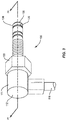
- the sensor assembly 10 includes a sensor probe 11 comprising a probe head 12 and a probe shaft 14.
- the probe shaft 14 extends from the probe head 12.
- the probe shaft 14 of existing sensor assemblies 10 are made from stainless steel.
- Stainless steel was generally considered an advantageous material due to its cost, manufacturability, reactivity, and resistance to rust, when considered for use under the harsh conditions found within the bearing housings of locomotives or under train cars generally. Threaded stainless steel parts also have the strength to receive significant torque during installation without stripping the threads.
- the probe head 12 can a rubber or thermoplastic sheath over-molded onto the end of the probe shaft 14 or other fabricated arrangement to protect the junction between the probe shaft and an exit cable 16.
- the exit cable 16 provides a connection from a temperature sensor 18, such as a thermistor, thermalcouple, or resistance temperature detector (RTD), packed within the probe shaft 14, to a measuring instrument, display, or control system.
- the temperature sensor 18 is a device that measures temperature directly or whose output may be converted to a specific or relative temperature reading. For example, a thermistor is monitored for a change in electrical resistance that results from a change in temperature of the thermistor. The resistance, resulting voltage, or change thereof, can be converted to a measure of the temperature at or near the thermistor.
- the probe shaft 14 has a longitudinal axis A and the exit cable 16 has a cable axis C.
- the sensor assembly 10 may be referred to as a right-angle sensor assembly.
- the present disclosure is not limited to right angle sensor assemblies but also contemplates other angles, including a generally collinear arrangement between the longitudinal axis A and the cable axis C (see FIG. 6 ).
- the probe shaft 14 includes a threaded tip 20 at the distal end opposite the probe head 12.
- a collar 22 is positioned around the probe shaft 14.
- the collar 22 often includes a hexhead 24 and a threaded end 26.
- the hexhead 24 is engageable by a wrench when the collar 22 is being threaded into engagement at its installed sensing position.
- An example of an installed sensing position is an access port into a bearing housing of a train car axle.
- Rotation between the probe shaft 14 and the collar 22 allows the collar to be screwed into engagement at the sensing position while leaving the sensor probe 11 to be freely adjusted and positioned. Therefore, removal and re-installation of the sensor assembly 10 can be accomplished without twisting or disconnecting the exit cable 16.
- the exit cable 16 can be positioned at any angle around the 360° of rotation, which allows for the exit cable to be used in a variety of positions.
- a seal 28 may be provided between the probe head 12 and the collar 22.
- the seal 28 can an O-ring, or be substantially flat, and has an aperture substantially equal to the diameter of the probe shaft 14 to allow the seal to be seated firmly between the collar 22 and the probe head 12.
- the seal 28 seals the gap between the probe head 12 and collar 22 to keep out elements such as water, dirt, or grease.
- the seal 28 is substantially smooth, to allow rotation between the probe head 12 and collar 22. When the collar 22 is fixed at the sensing position, the probe head 12 can rotate to position the exit cable 16 while maintaining a seal between the probe head and the collar.
- a nose piece 30 is attached onto the threaded tip 20 of the probe shaft 14.
- the nose piece 30 retains the collar 22 and the seal 28 along the probe shaft 14.
- the nose piece 30 is provided with one or more apertures 32, which are configured to receive a tool to tighten the nose piece 30 onto the probe shaft 14.
- the nose piece 30 of the existing sensor assembly 10 is made from stainless steel. Again, stainless steel helps avoid stripping the threads therein when subject to high torque during initial assembly onto the probe shaft 14. When initially developed, stainless steel was the clear choice for the metal components of the existing sensor assembly 10 due to its combination of strength, hardness, durability, resistant to corrosion, low cost, and ease of manufacturability.
- the temperature sensor assembly could be improved by developing a structure that facilitated an increased rate of heat transfer so that the temperature at the sensor element more quickly approaches the temperature of the assembly's environment.
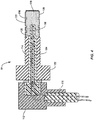
- At least a tip 120 of the probe shaft 114 of the sensor probe 111 is cast or otherwise manufactured from a material other than stainless steel, particularly a material having a thermal conductivity proportionality constant ( k ) greater than that of stainless steel, and preferably greater than thirty.
- the sensor probe 114 may be entirely formed from high thermal conductivity material or simply the tip 120.
- the tip 120 is adjacent to the temperature sensor 118 and therefore thermal conductivity at this location may be important. Having the remainder of the sensor probe 114 with a lower thermal conductivity may actually increase the rate of heat transfer from the environment to the temperature sensor 118 through the tip 120 by reducing the spread of heat energy from the tip 120 to the remainder of the sensor probe 114.
- copper has a k value (measured in BTU/h*ft*°F) exceeding two-hundred.
- Copper alloys which provide increased strength and hardness compared to pure copper, such as brass, bronze, or other copper containing alloys, also include k values greater than stainless steel. The specific k value is dependent upon the percentage of copper in the alloy. For example, a brass with 70% copper and 30% Zinc may have a k value of approximately eighty-five.
- Brass may be a particularly suitable material for the tip 120 of the sensor probe 114.
- the increased thermal conductivity provided by copper and copper alloys allows the heat around the probe shaft 114 to easily and more quickly reach and affect the temperature sensor 118, e.g. a thermistor, thermal couple, or RTD.
- Conventional approaches had selected stainless steel over brass because brass is a softer metal and is more easily damaged by excess torque. For this reason, brass was not seriously considered previously, particularly because stainless steel was believed to provide sufficient performance.
- the nose piece 130 is preferably, but not necessarily, also made from a copper alloy such as brass, to further increase heat conductivity between the ambient environment and the temperature sensor 118.
- the nose piece 130 may be used to secure a collar 122 and a seal 128 around the probe shaft 114.
- apertures 132 may be provided to receive a tool.
- the nose piece 130 may have flats instead of apertures 132 to provide similar assistance when the nose piece 130 is screwed or pressed onto the tip 120 of the probe shaft 114 with a tool.
- the nose piece 130 should be attached to the tip 120 of the probe shaft 114 in a manner which minimizes the air gap between the nose piece and the tip.
- Thermal grease may be used between the nose piece 130 and the tip 120 to minimize any air gaps.
- the collar 122 and the seal 128 may be substantially similar to the collar 22 and the seal 28 found on the existing sensor assembly 10.
- the collar 122 is capable of rotating relative to the probe shaft 114 during installation of the sensor assembly 100 thus allowing the sensor assembly to be installed or removed from a mounting area without twisting an exit cable 116 extending from the sensor probe 111 or disconnecting the exit cable from the sensor probe.
- the collar 122 remains fabricated from stainless steel because of the high torque applied when installing the sensor assembly 100.
- the collar 122 may be omitted and the probe shaft 114 may be directly attached to a sensing location.
- the nose piece 130 may be similarly omitted.
- a rubber or thermoplastic probe head 112 may be over-molded onto the end of the probe shaft 114 to protect the junction between the probe shaft and the exit cable 116 as both a seal against contaminants as well as a strain relief for the exit cable.
- the nose piece 130 is provided with a thin cladding 133 of nickel.
- the cladding 133 can help limit corrosion of the nose piece 130 and provide a silver appearance similar to the stainless steel appearance of existing nose pieces 30.
- the thin cladding of nickel is not believed to have a significant impact on the thermal conductivity path from the ambient environment to the temperature sensor 118. Nickel does, however, have a k value of approximately thirty-six.
- the probe shaft 114 is substantially hollow in order to house the temperature sensor 118.
- a resin epoxy 134 is used to secure the temperature sensor 118 within the probe shaft 114.
- the epoxy 134 is selected for its high thermal conductivity.
- the epoxy 134 should fill in the probe shaft 114 in a manner that minimizes air gaps between the temperature sensor 118 and the probe shaft.
- FIG. 5 shows the results of comparative testing between the existing sensor assembly 10 (see the dashed line) and an improved sensor assembly 100 as described above by altering some of the materials used to make the sensor assembly from stainless steel to brass (see the solid line).
- the comparative testing charts the sensor output in volts in relation to time since exposure to a 100 °C oil bath. Thus, the faster the voltage levels off, the faster the response time shown by the sensor assembly.
- the nose piece 130 was provided with a set of grooves 136 formed, e.g. machined, into the exterior surface 138 of the nose piece.
- the grooves 136 are formed circumferentially around the nose piece 130. These grooves 136 have the effect of reducing the amount of material between the ambient environment and the temperature sensor 118. Machining the grooves 136 into the nose piece 130 has the added benefit of reducing the mass of the sensor assembly 100. These grooves 136 also increase the surface area of the nose piece 130 that is exposed to the ambient environment being monitored.
- the nose piece 130 is provided with three grooves 136, two located axially on one side of the aperture 132 and one groove located on the other side of the aperture.
- the grooves 136 may be square grooves with 90 degree corners and edges as shown, or may be machined into the nose piece 130 with rounded features.
- the grooves 136 may each extend circumferentially around the entire nose piece 130 or may extend around only a portion of the circumference.
- the grooves 136 may be cut lengthwise along the nose piece 130.
- the grooves 136 are cut 1/16 inches wide along the longitudinal axis A.
- the grooves 136 may be cut to a depth of 1/64 inch or up to approximately one-half of the wall thickness of the nose piece 130.
- grooves includes other surface features that do not pass through the wall of the nose piece 130 which result in an increase in the area of the exterior surface 138, including but not limited to notches, threads, voids, indentations, channels, etc., that extend partially or fully around the circumference, parallel with the longitudinal axis A or with some angle in between.
- the results from the sensor assembly with the grooves 136 are shown in FIG. 5 with a dash-dot line.
- the addition of the grooves 136 even further improved the response time of the sensor assembly 100 compared to the existing sensor assembly 10. While the sensor assembly 100 has been described in terms of using grooves 136 on a brass based nose piece 130, other embodiments are envisioned where the nose piece 130 has grooves 136 or other surface features while being made from stainless steel.
- the improved sensor assemblies 100 showed a faster initiation time, i.e. the time before the temperature sensor 118 registered a change from initial temperature.
- the improved sensor assemblies 100 also displayed a faster overall response time, arriving at the true temperature equivalent voltage more quickly.
- both the improved sensor assembly 100 and the existing sensor assembly 10 were initially taken from room temperature and placed in an oil bath at one-hundred degrees centigrade. The temperature of the bath is equal to an output voltage of 1.4 volt in this experiment based upon the temperature sensor in use. While the improved sensor assemblies 100 reached the 1.4 volt level around 35 seconds, the existing sensor assembly 10 was still adjusting after 60 seconds. In fact, the average response time of the existing sensor assembly 10 was determined to be approximately 71 seconds (not shown), resulting in an approximate 50% improvement for the improved sensor assemblies 100.
- the sensor assembly 600 includes a sensor probe 611, a probe head 612, a probe shaft 614, an exit cable 616, a temperature sensor 618, a collar 622, and a nose piece 630.
- Each of the elements of the sensor assembly 600 is substantially equivalent to the corresponding features and elements of the sensor assembly 100.
- the primary distinction is that the longitudinal axis A is substantially coaxial with the cable axis C. Additionally, a jamb nut 650 may be provided to prevent the collar 622 from vibrating loose in high shock applications.
Landscapes
- Physics & Mathematics (AREA)
- General Physics & Mathematics (AREA)
- Nonlinear Science (AREA)
- Measuring Temperature Or Quantity Of Heat (AREA)
- Investigating Or Analyzing Materials By The Use Of Magnetic Means (AREA)
Claims (9)
- Ensemble capteur (100 ; 600) comprenant :une sonde de capteur (111 ; 611) comprenant une tête de sonde (112 ; 612) et une tige de sonde (114 ; 614), la tige de sonde s'étendant à partir de la tête de sonde le long d'un axe ;un capteur de température (118 ; 618) positionné à l'intérieur de la tige de sonde et adjacent à une pointe (120) de celle-ci ;un nez (130 ; 630) positionné sur la pointe de la tige de sonde à l'opposé de la tête de sonde ; etun collier (122 ; 622) positionné autour de la tige de sonde entre la tête de sonde et le nez, le collier (122 ; 622) étant capable de tourner par rapport à la tige de sonde (114 ; 614) lors de l'installation de l'ensemble capteur, ce qui permet à l'ensemble capteur (100 ; 600) d'être installé ou retiré d'une zone de montage sans tordre un câble (116 ; 616) s'étendant à partir de la sonde de capteur ou déconnecter le câble (116 ; 616) de la sonde de capteur, d'un câble de raccordement ou d'une boîte de jonction,caractérisé en ce qu'au moins la pointe de la tige de sonde (114 ; 614) comprend un matériau ayant une constante de proportionnalité de conductivité thermique supérieure à l'acier inoxydable, un revêtement de nickel (133) étant appliqué sur la surface extérieure du nez (130 ; 630).
- Ensemble capteur selon la revendication 1, dans lequel le nez (130 ; 630) comprend au moins une rainure (136) sur ou formée dans une surface extérieure de celui-ci.
- Ensemble capteur (100; 600) selon la revendication 2, dans lequel l'au moins une rainure comprend une pluralité de rainures (136) qui s'étendent autour d'une circonférence du nez (130 ; 630).
- Ensemble capteur (100; 600) selon une quelconque revendication précédente, dans lequel le capteur de température (118 ; 618) est maintenu à l'intérieur de la tige de sonde avec un époxy thermiquement conducteur (134).
- Ensemble capteur (100; 600) selon une quelconque revendication précédente, dans lequel le nez (130; 630) comprend un matériau ayant une constante de proportionnalité de conductivité thermique supérieure à l'acier inoxydable.
- Ensemble capteur (100; 600) selon une quelconque revendication précédente, dans lequel le nez (130; 630) comprend du laiton.
- Ensemble capteur (100; 600) selon une quelconque revendication précédente, dans lequel au moins la pointe de la tige de sonde (114 ; 614) comprend du laiton.
- Ensemble capteur (100; 600) selon une quelconque revendication précédente, dans lequel la constante de proportionnalité de conductivité thermique d'au moins la pointe de la tige de sonde (114 ; 614) et du nez (130 ; 630) est supérieure à trente.
- Ensemble capteur (100; 600) selon une quelconque revendication précédente, dans lequel le collier (122 ; 622) comprend un acier inoxydable.
Applications Claiming Priority (1)
| Application Number | Priority Date | Filing Date | Title |
|---|---|---|---|
| US15/651,025 US10859445B2 (en) | 2017-07-17 | 2017-07-17 | Temperature sensor assembly |
Publications (2)
| Publication Number | Publication Date |
|---|---|
| EP3431945A1 EP3431945A1 (fr) | 2019-01-23 |
| EP3431945B1 true EP3431945B1 (fr) | 2021-04-21 |
Family
ID=62975896
Family Applications (1)
| Application Number | Title | Priority Date | Filing Date |
|---|---|---|---|
| EP18183609.9A Active EP3431945B1 (fr) | 2017-07-17 | 2018-07-16 | Ensemble capteur de température |
Country Status (5)
| Country | Link |
|---|---|
| US (1) | US10859445B2 (fr) |
| EP (1) | EP3431945B1 (fr) |
| CN (1) | CN109269661A (fr) |
| BR (1) | BR102018014289B1 (fr) |
| CA (1) | CA3009559C (fr) |
Families Citing this family (5)
| Publication number | Priority date | Publication date | Assignee | Title |
|---|---|---|---|---|
| US11022321B1 (en) | 2019-12-16 | 2021-06-01 | June Life, Inc. | Cooking appliance accessory and method of use |
| USD1007224S1 (en) | 2021-06-11 | 2023-12-12 | June Life, Inc. | Cooking vessel |
| USD978600S1 (en) | 2021-06-11 | 2023-02-21 | June Life, Inc. | Cooking vessel |
| CN114812834B (zh) * | 2022-05-16 | 2025-08-29 | 新乡北方车辆仪表有限公司 | 一种螺纹连接耐高压温度传感器结构及其制作方法 |
| TWI848551B (zh) * | 2023-02-09 | 2024-07-11 | 熱映光電股份有限公司 | 溫度量測裝置 |
Citations (1)
| Publication number | Priority date | Publication date | Assignee | Title |
|---|---|---|---|---|
| US20140269820A1 (en) * | 2013-03-12 | 2014-09-18 | Rosemount Inc. | Thermowell insert |
Family Cites Families (15)
| Publication number | Priority date | Publication date | Assignee | Title |
|---|---|---|---|---|
| US4749415A (en) * | 1987-01-28 | 1988-06-07 | Westinghouse Electric Corp. | Fast response thermocouple element |
| US6923082B1 (en) | 1997-07-31 | 2005-08-02 | William L. Smith | Right angle sensor |
| US5918292A (en) | 1997-07-31 | 1999-06-29 | Smith; William L. | Right angle sensor |
| JP2002122486A (ja) * | 2000-08-11 | 2002-04-26 | Denso Corp | 温度センサの取付構造 |
| WO2003040673A2 (fr) * | 2001-11-02 | 2003-05-15 | Phipps Jack M | Capteur de temperature ameliorant la detection de la temperature de l'air ambiant |
| JP2006300649A (ja) | 2005-04-19 | 2006-11-02 | Yokohama Rubber Co Ltd:The | 温度測定器 |
| US7458718B2 (en) | 2006-02-22 | 2008-12-02 | Honeywell International Inc. | Temperature sensor that achieves a fast response in an exhaust gas environment |
| US20080016946A1 (en) * | 2006-07-18 | 2008-01-24 | Honeywell International Inc. | Gas sensor packaging for elevated temperature and harsh environment and related methods |
| US8417482B2 (en) * | 2010-07-12 | 2013-04-09 | R.W. Beckett Corporation | Self contained boiler sensor |
| CN202002748U (zh) * | 2011-03-02 | 2011-10-05 | 四川蜀谷仪表科技有限公司 | 一种铂电阻温度传感器 |
| KR102033700B1 (ko) | 2011-08-23 | 2019-10-17 | 스토너릿지 인코포레이티드 | 진동 감소 및/또는 조정 슬리브를 포함하는 배기가스 온도 센서 |
| US9341522B2 (en) * | 2013-05-01 | 2016-05-17 | Rosemount Inc. | Spring-loaded temperature sensor |
| US9920930B2 (en) | 2015-04-17 | 2018-03-20 | Honeywell International Inc. | Thermopile assembly with heat sink |
| CN105157862A (zh) * | 2015-08-27 | 2015-12-16 | 太仓飞顺温控设备有限公司 | 一种热电阻温度传感器 |
| CN106768453B (zh) * | 2016-11-22 | 2019-09-20 | 合肥舒实工贸有限公司 | 插装式温度传感器 |
-
2017
- 2017-07-17 US US15/651,025 patent/US10859445B2/en active Active
-
2018
- 2018-06-26 CA CA3009559A patent/CA3009559C/fr active Active
- 2018-07-13 BR BR102018014289-5A patent/BR102018014289B1/pt active IP Right Grant
- 2018-07-16 EP EP18183609.9A patent/EP3431945B1/fr active Active
- 2018-07-17 CN CN201810780297.6A patent/CN109269661A/zh active Pending
Patent Citations (1)
| Publication number | Priority date | Publication date | Assignee | Title |
|---|---|---|---|---|
| US20140269820A1 (en) * | 2013-03-12 | 2014-09-18 | Rosemount Inc. | Thermowell insert |
Also Published As
| Publication number | Publication date |
|---|---|
| BR102018014289A2 (pt) | 2019-03-06 |
| CA3009559C (fr) | 2021-08-17 |
| US10859445B2 (en) | 2020-12-08 |
| BR102018014289B1 (pt) | 2023-03-07 |
| CN109269661A (zh) | 2019-01-25 |
| US20190017880A1 (en) | 2019-01-17 |
| EP3431945A1 (fr) | 2019-01-23 |
| CA3009559A1 (fr) | 2019-01-17 |
Similar Documents
| Publication | Publication Date | Title |
|---|---|---|
| CA3009559C (fr) | Assemblage de capteur de temperature | |
| US5691707A (en) | Sensory fitting for monitoring bearing performance | |
| US6695483B2 (en) | Sensor and rolling bearing apparatus with sensor | |
| CN110715753B (zh) | 一种复合材料推力轴承在线监测油膜温度的装置及方法 | |
| US7018105B2 (en) | Bearing assembly with temperature sensor | |
| US10113585B2 (en) | Cabled bearing | |
| US20160273581A1 (en) | Wheel Bearing Assembly Having a Temperature-Measuring Device | |
| US7819026B2 (en) | Sensor-equipped wheel support bearing assembly | |
| US5896034A (en) | Method and apparatus for detecting and monitoring corrosion | |
| US20170211989A1 (en) | Method and device for assembling a temperature sensor | |
| KR101584435B1 (ko) | 와이퍼를 구비하는 볼 나사 | |
| US5122740A (en) | Rotational speed probe subassembly with shroud arranged for mounting probe transducer to a support housing | |
| JPS6046450A (ja) | 油圧システム用圧力流体状況モニタ装置 | |
| US7874732B2 (en) | Bearing device for drive wheel | |
| HK40003689A (en) | Temperature sensor assembly | |
| US5439296A (en) | Bearing housing with temperature switch | |
| KR20210068533A (ko) | 베어링 장치 및 예압 센서 | |
| DE102013018700B4 (de) | Einbauelement zur Aufnahme von Messmitteln | |
| US6498470B2 (en) | Insulative contact sensor | |
| JP4200380B2 (ja) | 鉄道車両用軸受装置 | |
| Klöcker et al. | Investigations of friction-relevant parameters to ensure reliable bolted joints | |
| JP2006312972A (ja) | 車両用軸受装置 | |
| US20050183522A1 (en) | Right angle sensor | |
| JP4235827B2 (ja) | 車両用軸受装置 | |
| KR101945412B1 (ko) | Rtd 케이블 설치 조립체 |
Legal Events
| Date | Code | Title | Description |
|---|---|---|---|
| PUAI | Public reference made under article 153(3) epc to a published international application that has entered the european phase |
Free format text: ORIGINAL CODE: 0009012 |
|
| STAA | Information on the status of an ep patent application or granted ep patent |
Free format text: STATUS: REQUEST FOR EXAMINATION WAS MADE |
|
| 17P | Request for examination filed |
Effective date: 20180716 |
|
| AK | Designated contracting states |
Kind code of ref document: A1 Designated state(s): AL AT BE BG CH CY CZ DE DK EE ES FI FR GB GR HR HU IE IS IT LI LT LU LV MC MK MT NL NO PL PT RO RS SE SI SK SM TR |
|
| AX | Request for extension of the european patent |
Extension state: BA ME |
|
| RBV | Designated contracting states (corrected) |
Designated state(s): AL AT BE BG CH CY CZ DE DK EE ES FI FR GB GR HR HU IE IS IT LI LT LU LV MC MK MT NL NO PL PT RO RS SE SI SK SM TR |
|
| STAA | Information on the status of an ep patent application or granted ep patent |
Free format text: STATUS: EXAMINATION IS IN PROGRESS |
|
| 17Q | First examination report despatched |
Effective date: 20200226 |
|
| GRAP | Despatch of communication of intention to grant a patent |
Free format text: ORIGINAL CODE: EPIDOSNIGR1 |
|
| STAA | Information on the status of an ep patent application or granted ep patent |
Free format text: STATUS: GRANT OF PATENT IS INTENDED |
|
| INTG | Intention to grant announced |
Effective date: 20201130 |
|
| GRAS | Grant fee paid |
Free format text: ORIGINAL CODE: EPIDOSNIGR3 |
|
| GRAA | (expected) grant |
Free format text: ORIGINAL CODE: 0009210 |
|
| STAA | Information on the status of an ep patent application or granted ep patent |
Free format text: STATUS: THE PATENT HAS BEEN GRANTED |
|
| AK | Designated contracting states |
Kind code of ref document: B1 Designated state(s): AL AT BE BG CH CY CZ DE DK EE ES FI FR GB GR HR HU IE IS IT LI LT LU LV MC MK MT NL NO PL PT RO RS SE SI SK SM TR |
|
| REG | Reference to a national code |
Ref country code: GB Ref legal event code: FG4D |
|
| REG | Reference to a national code |
Ref country code: CH Ref legal event code: EP |
|
| REG | Reference to a national code |
Ref country code: DE Ref legal event code: R096 Ref document number: 602018015743 Country of ref document: DE Ref country code: IE Ref legal event code: FG4D |
|
| REG | Reference to a national code |
Ref country code: AT Ref legal event code: REF Ref document number: 1385128 Country of ref document: AT Kind code of ref document: T Effective date: 20210515 |
|
| REG | Reference to a national code |
Ref country code: LT Ref legal event code: MG9D |
|
| REG | Reference to a national code |
Ref country code: AT Ref legal event code: MK05 Ref document number: 1385128 Country of ref document: AT Kind code of ref document: T Effective date: 20210421 |
|
| REG | Reference to a national code |
Ref country code: NL Ref legal event code: MP Effective date: 20210421 |
|
| PG25 | Lapsed in a contracting state [announced via postgrant information from national office to epo] |
Ref country code: LT Free format text: LAPSE BECAUSE OF FAILURE TO SUBMIT A TRANSLATION OF THE DESCRIPTION OR TO PAY THE FEE WITHIN THE PRESCRIBED TIME-LIMIT Effective date: 20210421 Ref country code: HR Free format text: LAPSE BECAUSE OF FAILURE TO SUBMIT A TRANSLATION OF THE DESCRIPTION OR TO PAY THE FEE WITHIN THE PRESCRIBED TIME-LIMIT Effective date: 20210421 Ref country code: FI Free format text: LAPSE BECAUSE OF FAILURE TO SUBMIT A TRANSLATION OF THE DESCRIPTION OR TO PAY THE FEE WITHIN THE PRESCRIBED TIME-LIMIT Effective date: 20210421 Ref country code: NL Free format text: LAPSE BECAUSE OF FAILURE TO SUBMIT A TRANSLATION OF THE DESCRIPTION OR TO PAY THE FEE WITHIN THE PRESCRIBED TIME-LIMIT Effective date: 20210421 Ref country code: AT Free format text: LAPSE BECAUSE OF FAILURE TO SUBMIT A TRANSLATION OF THE DESCRIPTION OR TO PAY THE FEE WITHIN THE PRESCRIBED TIME-LIMIT Effective date: 20210421 Ref country code: BG Free format text: LAPSE BECAUSE OF FAILURE TO SUBMIT A TRANSLATION OF THE DESCRIPTION OR TO PAY THE FEE WITHIN THE PRESCRIBED TIME-LIMIT Effective date: 20210721 |
|
| PG25 | Lapsed in a contracting state [announced via postgrant information from national office to epo] |
Ref country code: RS Free format text: LAPSE BECAUSE OF FAILURE TO SUBMIT A TRANSLATION OF THE DESCRIPTION OR TO PAY THE FEE WITHIN THE PRESCRIBED TIME-LIMIT Effective date: 20210421 Ref country code: SE Free format text: LAPSE BECAUSE OF FAILURE TO SUBMIT A TRANSLATION OF THE DESCRIPTION OR TO PAY THE FEE WITHIN THE PRESCRIBED TIME-LIMIT Effective date: 20210421 Ref country code: NO Free format text: LAPSE BECAUSE OF FAILURE TO SUBMIT A TRANSLATION OF THE DESCRIPTION OR TO PAY THE FEE WITHIN THE PRESCRIBED TIME-LIMIT Effective date: 20210721 Ref country code: LV Free format text: LAPSE BECAUSE OF FAILURE TO SUBMIT A TRANSLATION OF THE DESCRIPTION OR TO PAY THE FEE WITHIN THE PRESCRIBED TIME-LIMIT Effective date: 20210421 Ref country code: PL Free format text: LAPSE BECAUSE OF FAILURE TO SUBMIT A TRANSLATION OF THE DESCRIPTION OR TO PAY THE FEE WITHIN THE PRESCRIBED TIME-LIMIT Effective date: 20210421 Ref country code: PT Free format text: LAPSE BECAUSE OF FAILURE TO SUBMIT A TRANSLATION OF THE DESCRIPTION OR TO PAY THE FEE WITHIN THE PRESCRIBED TIME-LIMIT Effective date: 20210823 Ref country code: GR Free format text: LAPSE BECAUSE OF FAILURE TO SUBMIT A TRANSLATION OF THE DESCRIPTION OR TO PAY THE FEE WITHIN THE PRESCRIBED TIME-LIMIT Effective date: 20210722 Ref country code: IS Free format text: LAPSE BECAUSE OF FAILURE TO SUBMIT A TRANSLATION OF THE DESCRIPTION OR TO PAY THE FEE WITHIN THE PRESCRIBED TIME-LIMIT Effective date: 20210821 |
|
| REG | Reference to a national code |
Ref country code: DE Ref legal event code: R097 Ref document number: 602018015743 Country of ref document: DE |
|
| PG25 | Lapsed in a contracting state [announced via postgrant information from national office to epo] |
Ref country code: SM Free format text: LAPSE BECAUSE OF FAILURE TO SUBMIT A TRANSLATION OF THE DESCRIPTION OR TO PAY THE FEE WITHIN THE PRESCRIBED TIME-LIMIT Effective date: 20210421 Ref country code: SK Free format text: LAPSE BECAUSE OF FAILURE TO SUBMIT A TRANSLATION OF THE DESCRIPTION OR TO PAY THE FEE WITHIN THE PRESCRIBED TIME-LIMIT Effective date: 20210421 Ref country code: EE Free format text: LAPSE BECAUSE OF FAILURE TO SUBMIT A TRANSLATION OF THE DESCRIPTION OR TO PAY THE FEE WITHIN THE PRESCRIBED TIME-LIMIT Effective date: 20210421 Ref country code: ES Free format text: LAPSE BECAUSE OF FAILURE TO SUBMIT A TRANSLATION OF THE DESCRIPTION OR TO PAY THE FEE WITHIN THE PRESCRIBED TIME-LIMIT Effective date: 20210421 Ref country code: RO Free format text: LAPSE BECAUSE OF FAILURE TO SUBMIT A TRANSLATION OF THE DESCRIPTION OR TO PAY THE FEE WITHIN THE PRESCRIBED TIME-LIMIT Effective date: 20210421 Ref country code: CZ Free format text: LAPSE BECAUSE OF FAILURE TO SUBMIT A TRANSLATION OF THE DESCRIPTION OR TO PAY THE FEE WITHIN THE PRESCRIBED TIME-LIMIT Effective date: 20210421 Ref country code: DK Free format text: LAPSE BECAUSE OF FAILURE TO SUBMIT A TRANSLATION OF THE DESCRIPTION OR TO PAY THE FEE WITHIN THE PRESCRIBED TIME-LIMIT Effective date: 20210421 |
|
| PLBE | No opposition filed within time limit |
Free format text: ORIGINAL CODE: 0009261 |
|
| STAA | Information on the status of an ep patent application or granted ep patent |
Free format text: STATUS: NO OPPOSITION FILED WITHIN TIME LIMIT |
|
| 26N | No opposition filed |
Effective date: 20220124 |
|
| PG25 | Lapsed in a contracting state [announced via postgrant information from national office to epo] |
Ref country code: MC Free format text: LAPSE BECAUSE OF FAILURE TO SUBMIT A TRANSLATION OF THE DESCRIPTION OR TO PAY THE FEE WITHIN THE PRESCRIBED TIME-LIMIT Effective date: 20210421 |
|
| REG | Reference to a national code |
Ref country code: BE Ref legal event code: MM Effective date: 20210731 |
|
| PG25 | Lapsed in a contracting state [announced via postgrant information from national office to epo] |
Ref country code: IS Free format text: LAPSE BECAUSE OF FAILURE TO SUBMIT A TRANSLATION OF THE DESCRIPTION OR TO PAY THE FEE WITHIN THE PRESCRIBED TIME-LIMIT Effective date: 20210821 Ref country code: LU Free format text: LAPSE BECAUSE OF NON-PAYMENT OF DUE FEES Effective date: 20210716 Ref country code: AL Free format text: LAPSE BECAUSE OF FAILURE TO SUBMIT A TRANSLATION OF THE DESCRIPTION OR TO PAY THE FEE WITHIN THE PRESCRIBED TIME-LIMIT Effective date: 20210421 |
|
| PG25 | Lapsed in a contracting state [announced via postgrant information from national office to epo] |
Ref country code: IT Free format text: LAPSE BECAUSE OF FAILURE TO SUBMIT A TRANSLATION OF THE DESCRIPTION OR TO PAY THE FEE WITHIN THE PRESCRIBED TIME-LIMIT Effective date: 20210421 Ref country code: IE Free format text: LAPSE BECAUSE OF NON-PAYMENT OF DUE FEES Effective date: 20210716 Ref country code: BE Free format text: LAPSE BECAUSE OF NON-PAYMENT OF DUE FEES Effective date: 20210731 |
|
| P01 | Opt-out of the competence of the unified patent court (upc) registered |
Effective date: 20230517 |
|
| PG25 | Lapsed in a contracting state [announced via postgrant information from national office to epo] |
Ref country code: CY Free format text: LAPSE BECAUSE OF FAILURE TO SUBMIT A TRANSLATION OF THE DESCRIPTION OR TO PAY THE FEE WITHIN THE PRESCRIBED TIME-LIMIT Effective date: 20210421 |
|
| PG25 | Lapsed in a contracting state [announced via postgrant information from national office to epo] |
Ref country code: HU Free format text: LAPSE BECAUSE OF FAILURE TO SUBMIT A TRANSLATION OF THE DESCRIPTION OR TO PAY THE FEE WITHIN THE PRESCRIBED TIME-LIMIT; INVALID AB INITIO Effective date: 20180716 |
|
| PG25 | Lapsed in a contracting state [announced via postgrant information from national office to epo] |
Ref country code: MK Free format text: LAPSE BECAUSE OF FAILURE TO SUBMIT A TRANSLATION OF THE DESCRIPTION OR TO PAY THE FEE WITHIN THE PRESCRIBED TIME-LIMIT Effective date: 20210421 |
|
| PG25 | Lapsed in a contracting state [announced via postgrant information from national office to epo] |
Ref country code: TR Free format text: LAPSE BECAUSE OF FAILURE TO SUBMIT A TRANSLATION OF THE DESCRIPTION OR TO PAY THE FEE WITHIN THE PRESCRIBED TIME-LIMIT Effective date: 20210421 |
|
| PG25 | Lapsed in a contracting state [announced via postgrant information from national office to epo] |
Ref country code: MT Free format text: LAPSE BECAUSE OF FAILURE TO SUBMIT A TRANSLATION OF THE DESCRIPTION OR TO PAY THE FEE WITHIN THE PRESCRIBED TIME-LIMIT Effective date: 20210421 |
|
| PGFP | Annual fee paid to national office [announced via postgrant information from national office to epo] |
Ref country code: DE Payment date: 20250729 Year of fee payment: 8 |
|
| PGFP | Annual fee paid to national office [announced via postgrant information from national office to epo] |
Ref country code: GB Payment date: 20250728 Year of fee payment: 8 |
|
| PGFP | Annual fee paid to national office [announced via postgrant information from national office to epo] |
Ref country code: FR Payment date: 20250725 Year of fee payment: 8 |
|
| PGFP | Annual fee paid to national office [announced via postgrant information from national office to epo] |
Ref country code: CH Payment date: 20250801 Year of fee payment: 8 |