EP3432464A1 - Mehrachsiges motorsteuerungssystem - Google Patents
Mehrachsiges motorsteuerungssystem Download PDFInfo
- Publication number
- EP3432464A1 EP3432464A1 EP17766473.7A EP17766473A EP3432464A1 EP 3432464 A1 EP3432464 A1 EP 3432464A1 EP 17766473 A EP17766473 A EP 17766473A EP 3432464 A1 EP3432464 A1 EP 3432464A1
- Authority
- EP
- European Patent Office
- Prior art keywords
- motor control
- controller
- motor
- stop
- control devices
- Prior art date
- Legal status (The legal status is an assumption and is not a legal conclusion. Google has not performed a legal analysis and makes no representation as to the accuracy of the status listed.)
- Granted
Links
Images


Classifications
-
- H—ELECTRICITY
- H02—GENERATION; CONVERSION OR DISTRIBUTION OF ELECTRIC POWER
- H02P—CONTROL OR REGULATION OF ELECTRIC MOTORS, ELECTRIC GENERATORS OR DYNAMO-ELECTRIC CONVERTERS; CONTROLLING TRANSFORMERS, REACTORS OR CHOKE COILS
- H02P6/00—Arrangements for controlling synchronous motors or other dynamo-electric motors using electronic commutation dependent on the rotor position; Electronic commutators therefor
- H02P6/12—Monitoring commutation; Providing indication of commutation failure
-
- H—ELECTRICITY
- H02—GENERATION; CONVERSION OR DISTRIBUTION OF ELECTRIC POWER
- H02P—CONTROL OR REGULATION OF ELECTRIC MOTORS, ELECTRIC GENERATORS OR DYNAMO-ELECTRIC CONVERTERS; CONTROLLING TRANSFORMERS, REACTORS OR CHOKE COILS
- H02P3/00—Arrangements for stopping or slowing electric motors, generators, or dynamo-electric converters
- H02P3/06—Arrangements for stopping or slowing electric motors, generators, or dynamo-electric converters for stopping or slowing an individual dynamo-electric motor or dynamo-electric converter
- H02P3/18—Arrangements for stopping or slowing electric motors, generators, or dynamo-electric converters for stopping or slowing an individual dynamo-electric motor or dynamo-electric converter for stopping or slowing an AC motor
- H02P3/22—Arrangements for stopping or slowing electric motors, generators, or dynamo-electric converters for stopping or slowing an individual dynamo-electric motor or dynamo-electric converter for stopping or slowing an AC motor by short-circuit or resistive braking
-
- G—PHYSICS
- G05—CONTROLLING; REGULATING
- G05B—CONTROL OR REGULATING SYSTEMS IN GENERAL; FUNCTIONAL ELEMENTS OF SUCH SYSTEMS; MONITORING OR TESTING ARRANGEMENTS FOR SUCH SYSTEMS OR ELEMENTS
- G05B19/00—Program-control systems
- G05B19/02—Program-control systems electric
- G05B19/18—Numerical control [NC], i.e. automatically operating machines, in particular machine tools, e.g. in a manufacturing environment, so as to execute positioning, movement or co-ordinated operations by means of program data in numerical form
- G05B19/19—Numerical control [NC], i.e. automatically operating machines, in particular machine tools, e.g. in a manufacturing environment, so as to execute positioning, movement or co-ordinated operations by means of program data in numerical form characterised by positioning or contouring control systems, e.g. to control position from one programmed point to another or to control movement along a programmed continuous path
-
- G—PHYSICS
- G05—CONTROLLING; REGULATING
- G05B—CONTROL OR REGULATING SYSTEMS IN GENERAL; FUNCTIONAL ELEMENTS OF SUCH SYSTEMS; MONITORING OR TESTING ARRANGEMENTS FOR SUCH SYSTEMS OR ELEMENTS
- G05B19/00—Program-control systems
- G05B19/02—Program-control systems electric
- G05B19/18—Numerical control [NC], i.e. automatically operating machines, in particular machine tools, e.g. in a manufacturing environment, so as to execute positioning, movement or co-ordinated operations by means of program data in numerical form
- G05B19/414—Structure of the control system, e.g. common controller or multiprocessor systems, interface to servo, programmable interface controller
- G05B19/4141—Structure of the control system, e.g. common controller or multiprocessor systems, interface to servo, programmable interface controller characterised by a controller or microprocessor per axis
-
- H—ELECTRICITY
- H02—GENERATION; CONVERSION OR DISTRIBUTION OF ELECTRIC POWER
- H02P—CONTROL OR REGULATION OF ELECTRIC MOTORS, ELECTRIC GENERATORS OR DYNAMO-ELECTRIC CONVERTERS; CONTROLLING TRANSFORMERS, REACTORS OR CHOKE COILS
- H02P5/00—Arrangements specially adapted for regulating or controlling the speed or torque of two or more electric motors
- H02P5/46—Arrangements specially adapted for regulating or controlling the speed or torque of two or more electric motors for speed regulation of two or more dynamo-electric motors in relation to one another
-
- H—ELECTRICITY
- H02—GENERATION; CONVERSION OR DISTRIBUTION OF ELECTRIC POWER
- H02P—CONTROL OR REGULATION OF ELECTRIC MOTORS, ELECTRIC GENERATORS OR DYNAMO-ELECTRIC CONVERTERS; CONTROLLING TRANSFORMERS, REACTORS OR CHOKE COILS
- H02P5/00—Arrangements specially adapted for regulating or controlling the speed or torque of two or more electric motors
- H02P5/74—Arrangements specially adapted for regulating or controlling the speed or torque of two or more electric motors controlling two or more AC dynamo-electric motors
-
- H—ELECTRICITY
- H02—GENERATION; CONVERSION OR DISTRIBUTION OF ELECTRIC POWER
- H02P—CONTROL OR REGULATION OF ELECTRIC MOTORS, ELECTRIC GENERATORS OR DYNAMO-ELECTRIC CONVERTERS; CONTROLLING TRANSFORMERS, REACTORS OR CHOKE COILS
- H02P6/00—Arrangements for controlling synchronous motors or other dynamo-electric motors using electronic commutation dependent on the rotor position; Electronic commutators therefor
- H02P6/14—Electronic commutators
- H02P6/16—Circuit arrangements for detecting position
- H02P6/17—Circuit arrangements for detecting position and for generating speed information
-
- H—ELECTRICITY
- H02—GENERATION; CONVERSION OR DISTRIBUTION OF ELECTRIC POWER
- H02P—CONTROL OR REGULATION OF ELECTRIC MOTORS, ELECTRIC GENERATORS OR DYNAMO-ELECTRIC CONVERTERS; CONTROLLING TRANSFORMERS, REACTORS OR CHOKE COILS
- H02P6/00—Arrangements for controlling synchronous motors or other dynamo-electric motors using electronic commutation dependent on the rotor position; Electronic commutators therefor
- H02P6/24—Arrangements for stopping
-
- G—PHYSICS
- G05—CONTROLLING; REGULATING
- G05B—CONTROL OR REGULATING SYSTEMS IN GENERAL; FUNCTIONAL ELEMENTS OF SUCH SYSTEMS; MONITORING OR TESTING ARRANGEMENTS FOR SUCH SYSTEMS OR ELEMENTS
- G05B2219/00—Program-control systems
- G05B2219/30—Nc systems
- G05B2219/42—Servomotor, servo controller kind till VSS
- G05B2219/42284—Stop and brake motor
-
- H—ELECTRICITY
- H02—GENERATION; CONVERSION OR DISTRIBUTION OF ELECTRIC POWER
- H02P—CONTROL OR REGULATION OF ELECTRIC MOTORS, ELECTRIC GENERATORS OR DYNAMO-ELECTRIC CONVERTERS; CONTROLLING TRANSFORMERS, REACTORS OR CHOKE COILS
- H02P3/00—Arrangements for stopping or slowing electric motors, generators, or dynamo-electric converters
- H02P3/06—Arrangements for stopping or slowing electric motors, generators, or dynamo-electric converters for stopping or slowing an individual dynamo-electric motor or dynamo-electric converter
- H02P3/08—Arrangements for stopping or slowing electric motors, generators, or dynamo-electric converters for stopping or slowing an individual dynamo-electric motor or dynamo-electric converter for stopping or slowing a DC motor
- H02P3/12—Arrangements for stopping or slowing electric motors, generators, or dynamo-electric converters for stopping or slowing an individual dynamo-electric motor or dynamo-electric converter for stopping or slowing a DC motor by short-circuit or resistive braking
-
- H—ELECTRICITY
- H04—ELECTRIC COMMUNICATION TECHNIQUE
- H04L—TRANSMISSION OF DIGITAL INFORMATION, e.g. TELEGRAPHIC COMMUNICATION
- H04L12/00—Data switching networks
- H04L12/28—Data switching networks characterised by path configuration, e.g. LAN [Local Area Networks] or WAN [Wide Area Networks]
- H04L12/40—Bus networks
- H04L2012/4026—Bus for use in automation systems
-
- H—ELECTRICITY
- H04—ELECTRIC COMMUNICATION TECHNIQUE
- H04L—TRANSMISSION OF DIGITAL INFORMATION, e.g. TELEGRAPHIC COMMUNICATION
- H04L12/00—Data switching networks
- H04L12/54—Store-and-forward switching systems
- H04L12/56—Packet switching systems
- H04L12/5601—Transfer mode dependent, e.g. ATM
- H04L2012/5603—Access techniques
- H04L2012/5609—Topology
- H04L2012/5612—Ring
Definitions
- the present invention relates to a motor control system configured to control a multiaxial machine including a plurality of shafts.
- Such a conventional multiaxial motor control system executes emergency stop in the following manner.
- the conventional system includes a controller configured to control motor control devices for a plurality of shafts via communication lines.
- the motor control device for the malfunctioning shaft initializes motor positional deviation information and notifies a functioning shaft with no malfunction of malfunction occurrence information and motor driven position information.
- the motor control device for the functioning shaft simultaneously causes the functioning shaft to be controlled to follow the malfunctioning shaft in accordance with the malfunction occurrence information and the motor driven position information thus received on the malfunctioning shaft.
- This conventional system drives and controls to cause the functioning shaft to follow in accordance with the position information on the malfunctioning shaft to decrease an interaxial error between the functioning shaft and the malfunctioning shaft and eventually stop the shafts at an identical position.
- the conventional system adopts a technique of executing such control to emergently stop the plurality of shafts in synchronization with each other.
- the present invention provides a multiaxial motor control system configured to control motors for a plurality of shafts included in a multiaxial machine.
- the multiaxial motor control system includes a plurality of motor control devices and a controller.
- the controller has network connection with the motor control devices, and transmits a command signal for control of the motor control devices.
- Each of the motor control devices includes a communication controller, a rotation controller, and a drive unit, and is configured to drive a corresponding one of the motors for the plurality of shafts.
- the communication controller receives the command signal, transmits the received command signal, and determines whether or not the command signal is received normally.
- the rotation controller generates a torque command for operation of the corresponding one of the motors.
- the drive unit generates a drive voltage for electrification to drive the corresponding one of the motors in accordance with the torque command.
- the at least one of the motor control devices in the multiaxial motor control system detects failure in reception of the command signal, the at least one of the motor control devices outputs a torque command for braking torque to stop the corresponding one of the motors.
- At least one of the motor control devices applies braking torque with the motor keeping being electrified even during communication failure that some of the motor control devices fail to receive a command signal from the controller by network communication.
- the multiaxial motor control system is thus configured to stop the motor in a braking distance shorter than a conventional braking distance.
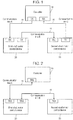
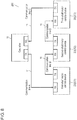
- FIG. 1 is a block diagram depicting a ring network configuration as an exemplary basic configuration of a multiaxial motor control system.
- FIG. 2 is a block diagram depicting a line network configuration as another exemplary basic configuration of the multiaxial motor control system.
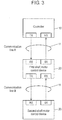
- FIG. 3 is a diagram depicting still another exemplary basic configuration of the multiaxial motor control system having the line network.
- Each of these configurations includes a plurality of motor control devices 20 each configured to drive and control a corresponding motor and controller 10 configured to control motor control devices 20.
- Controller 10 and motor control devices 20 are communicably connected via communication lines 11 to achieve transmission and reception of data.
- FIG. 1 to FIG. 3 each depict an exemplarily configuration of the system including two, namely, first-shaft and second-shaft motor control devices 20 corresponding to respective shafts included in a multiaxial mechanism.
- a multiaxial motor control system is configured as to be described later in accordance with the basic configuration depicted in FIG. 1, FIG. 2 , or FIG. 3 to cause at least one motor control device 20 to output braking torque during failure or the like to emergently stop the corresponding motor.
- Each of the exemplary embodiments thus achieves stopping the motor in a braking distance shorter than a conventional braking distance.
- the above conventional emergency stop technique accordingly requires a dedicated notification device configured to notify the functioning shaft of position information and the like on the malfunctioning shaft.
- the configurations depicted in FIG. 1, FIG. 2 , and FIG. 3 each disconnect communication between motor control devices 20 in an exemplary case where communication line 11 between motor control devices 20 is broken. None of these configurations thus achieves control between the malfunctioning shaft and the functioning shaft.
- the conventional motor control system having ring or line connection adopts a method of stopping by immediately disconnecting electrification to the motor for the malfunctioning shaft and the motor for the functioning shaft.
- This technique requires a long braking distance until each of the motors stops because the motor is self-propelled for a while after electrification is disconnected.
- This technique has safety problems such as that immediate stop causes strong stress to be applied to a load to damage the device while the braking distance can be shortened.
- At least one motor control device 20 is configured to output braking torque to stop the motor, to suppress stress applied to a load and stop the motor in a short braking distance.
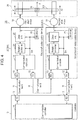
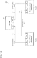
- FIG. 4 is a block diagram depicting a configuration of ring multiaxial motor control system 100 according to a first exemplary embodiment of the present invention.
- multiaxial motor control system 100 configures a biaxial motor control system including controller 10 and two motor control devices 20 communicably connected via communication lines 11 to form a ring shape.
- Multiaxial motor control system 100 includes one-to-one unidirectional connection between units according to ring network topology.
- Controller 10 transmits a command signal for a position command, a speed command, or the like to first-shaft and second-shaft motor control devices 20, in every command update period as a reference period for transmission of a command signal.
- Each motor control device 20 controls operation of motor 30 in accordance with the received command signal.
- the first-shaft motor control device will be identified as motor control device 201 and the second-shaft motor control device will be identified as motor control device 202 for appropriate specification of motor control devices 20, while each of the motor control devices will generically be called motor control device 20.
- FIG. 4 depicts control target mechanism 35 as a control target of motors 30, including two shafts mechanically linked by link 351, specifically, shaft X1 controlled by first-shaft motor 30 and shaft X2 controlled by second-shaft motor 30.
- Control target mechanism 35 exemplifies a multiaxial machine as a multiaxial mechanism having a gantry structure.
- Control target mechanism 35 has the gantry structure, so that motors 30 for shafts X1 and X2 are ordinarily controlled through synchronized processing for the both shafts according to same commands.
- the present exemplary embodiment provides control of a position in an X direction of load 36 such that shaft X1 and shaft X2 in such a multiaxial mechanism move positionally equally in the X direction at equal speed.
- controller 10 includes transmitter 12 configured to transmit data such as a command signal, receiver 13 configured to receive data, and communication controller 14 configured to control communication by transmitter 12 and receiver 13, provide and receive communication data, and the like.
- Each motor control device 20 similarly includes transmitter 12 configured to transmit data, receiver 13 configured to receive data, and communication controller 14 configured to control transmitter 12 and receiver 13.
- Controller 10 and motor control devices 20 are interconnected via communication lines 11 to form a ring shape so as to achieve transfer of data from transmitter 12 to receiver 13.
- FIG. 4 depicts network connection between communication controller 14 in controller 10 and communication controller 14 in motor control device 201, for data transfer via communication line 11 specified as communication line A.
- communication controller 14 in motor control device 201 and communication controller 14 in motor control device 202 have network connection for data transfer via communication line 11 specified as communication line B.
- communication controller 14 in motor control device 202 and communication controller 14 in controller 10 have network connection for data transfer via communication line 11 specified as communication line C.
- Such connection enables communication by unidirectional ring connection of controller 10, motor control device 201, motor control device 202, and controller 10 in the mentioned order.
- each communication controller 14 is configured to normally provide and receive a command signal or a response signal indicating data reception, as well as detect failure in communication (transmission or reception).
- Examples of possible communication failure in such multiaxial motor control system 100 include break of any communication line 11, and failure in data recovery even if any communication controller 14 corrects any error in communication data. Motor control device 20 then cannot receive a command signal from controller 10 and cannot continue normally operating the corresponding motor. Examples of the error to be corrected include a parity error, a check sum error, and a cyclic redundancy check (CRC) error.
- CRC cyclic redundancy check
- each motor control device 20 further includes rotation controller 24 and drive unit 25 to drive and control motor 30.
- Each of rotation controller 24 and drive unit 25 according to the present exemplary embodiment also has a function for emergently stopping motor 30.
- each motor control device 20 further includes dynamic brake (hereinafter, abbreviated as DB where appropriate) circuit 26 configured to brake motor 30 as a closed circuit including a resistor.
- DB dynamic brake
- the function for emergency stop of each of rotation controller 24 and drive unit 25, and DB circuit 26 are selectively adopted in accordance with stop command Em from communication controller 14 in the present exemplary embodiment.
- multiaxial motor control system 100 includes motor control devices 20 each configured to individually drive and stop motor 30.
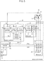
- FIG. 5 is a block diagram depicting a detailed exemplary configuration of motor control device 20 thus configured according to the first exemplary embodiment of the present invention. The detailed configuration of motor control device 20 will be described next with reference to FIG. 5 .
- FIG. 5 exemplifies a case where motor 30 is a brushless motor that is driven in three phases of U, V, and W phases.
- motor 30 includes a stator provided with coils 31 corresponding to the respective phases and a rotor retaining a permanent magnet. Coils 31 of the stator are electrified when receiving drive voltages Vd differentiated in phase from each other by 120 degrees. In this case, electric current flows through coils 31 to rotate the rotor.
- the corresponding shaft connected to the rotor is positionally controlled in accordance with rotation of the rotor.
- each motor control device 20 includes rotation controller 24 configured to control a position, speed, and torque of motor 30, and drive unit 25 configured to electrify to drive coils 31 of motor 30.
- Rotation controller 24 includes position controller 41 configured to control a position, speed controller 43 configured to control speed, torque processor 46 configured to execute torque-related processing , and the like.
- Drive unit 25 includes drive output generator 51 configured to generate a drive voltage corresponding to a torque amount received from rotation controller 24.
- each motor control device 20 includes DB circuit 26, rotation controller 24 including torque amount storage 44, and drive unit 25 including drive voltage switch 53.
- Controller 10 notifies each motor control device 20 thus configured of command information by means of a command signal.
- major command information included in the command signal include position command Prc to position controller 41, speed command Src to speed controller 43, a torque command to torque processor 46, and stop command Em relevant to emergency stop, such as activation or deactivation of DB circuit 26.
- FIG. 5 typically depicts a configuration in which communication controller 14 transmits position command Prc to position controller 41, transmits speed command Src to speed controller 43, and transmits stop command Em to each of rotation controller 24, drive unit 25, and DB circuit 26, in accordance with the received command signal.
- position detector 32 disposed at motor 30 notifies position controller 41 of detected position information Pd indicating a position of the rotor in motor 30.
- rotation controller 24 controls rotation such that a rotational position of the rotor in motor 30 follows position command Prc from controller 10 or the like through feedback control with reference to detected position information Pd from position detector 32.
- position controller 41 in rotation controller 24 initially calculates a positional deviation as difference between position command Prc and detected position information Pd from position detector 32. Position controller 41 then obtains speed command Sr by arithmetic operation such as multiplication of the positional deviation by a position gain, and notifies speed controller 43 of obtained speed command Sr.
- Speed controller 43 subsequently obtains rotational speed of motor 30 by arithmetic operation such as differentiation of detected position information Pd thus received. Speed controller 43 further calculates a speed deviation as difference between the calculated rotational speed and speed command Sr. Speed controller 43 then executes arithmetic operation such as proportion and integration of the speed deviation to obtain torque command Tr corresponding to a driving torque amount of operating motor 30. Speed controller 43 notifies torque processor 46 of torque command Tr thus obtained.
- Torque processor 46 then transmits, to drive unit 25, torque command Tr corresponding to the driving torque amount as voltage command signal Dr, in a case where communication failure or the like does not occur.
- Drive unit 25 generates drive voltage Vd in accordance with voltage command signal Dr provided from rotation controller 24.
- drive output generator 51 includes an inverter having a pulse width modulation (PWM) circuit and a switching element.
- PWM pulse width modulation
- Drive output generator 51 generates a pulse signal that is pulse width modulated by the PWM circuit in accordance with voltage command signal Dr, and generates drive voltage Vd through ON/OFF control of the switching element in the inverter in accordance with the pulse signal.
- drive unit 25 applies, to coils 31 for the respective phases via drive voltage switch 53 in an ON state, drive voltage Vd thus generated to drive motor 30.
- DB circuit 26 includes DB switches 61 and DB resistors 63.
- DB switches 61 in DB circuit 26 are each configured to switch between connection and disconnection of corresponding DB resistor 63 with respect to drive voltage Vd thus output from drive unit 25.
- Multiaxial motor control system 100 thus configured may have break or the like of at least one of communication lines 11, namely, communication line A, communication line B, or communication line C, or failure in communication function or the like of any motor control device 20. Furthermore, there may occur communication failure such as that any motor control device 20 cannot receive a command signal from controller 10 or cannot transmit a response signal to controller 10.
- motor control device 20 selectively adopts the function for emergency stop of each of rotation controller 24 and drive unit 25 or DB circuit 26 to stop driving the corresponding motor when such communication failure is detected.
- the present exemplary embodiment provides the following three functions for stop of driving the motor.
- These functions include a first function (hereinafter, called an immediate stop function) of immediately stopping motor 30 by causing rotation controller 24 to generate braking torque.
- speed controller 43 is configured to operate in accordance with a zero speed command as a speed command for speed of zero.
- Rotation controller 24 includes torque amount storage 44 configured to store a preset braking torque amount and the like.
- motor control device 20 is configured to cause communication controller 14 to notify speed controller 43 and torque processor 46 of stop command Em1. This immediate stop function is activated or deactivated in accordance with stop command Em1.
- stop command Em1 indicates deactivation of immediate stop
- speed controller 43 calculates torque command Tr following speed command Sr from position controller 41 or speed command Src from communication controller 14, and outputs calculated torque command Tr.
- the immediate stop is deactivated in this case.
- Torque processor 46 accordingly selects torque command Tr from speed controller 43 and transmits voltage command signal Dr corresponding to torque command Tr to drive unit 25. Normal operation thus continues.
- speed controller 43 initially switches from operation according to speed command Sr or speed command Src to operation according to the zero speed command. Motor 30 in operation at certain speed is then controlled to have zero speed, and speed controller 43 generates torque command Tr corresponding to braking torque for stopping rotation of motor 30.
- the immediate stop is activated in this case.
- Torque processor 46 accordingly reads out of torque amount storage 44 braking torque command Tb indicating a predetermined braking torque amount, and transmits voltage command signal Dr corresponding to braking torque command Tb to drive unit 25.
- Drive unit 25 accordingly applies, to each coil 31, drive voltage Vd for braking rotation of motor 30, and rotation of motor 30 is stopped.
- the functions for stop of driving the motor also includes a second function (hereinafter, called a non-drive stop function) of naturally stopping motor 30 by stopping supply of drive voltage Vd from drive unit 25 to motor 30.
- drive unit 25 includes drive voltage switch 53 configured to switch between connection and disconnection of the drive voltage output from drive output generator 51 to and from coils 31 in motor 30.
- Drive voltage switch 53 is switched ON or OFF in accordance with second stop command Em2 from communication controller 14 as depicted in FIG. 5 .
- stop command Em2 indicates deactivation of non-drive stop
- drive voltage switch 53 is ON, and drive output generator 51 is connected to coils 31 to enable transmission.
- Drive unit 25 accordingly supplies coils 31 with a voltage output from drive output generator 51 as drive voltage Vd.
- stop command Em2 indicates activation of the non-drive stop
- drive voltage switch 53 is switched OFF and drive unit 25 is disconnected from coils 31 to disable transmission. In this disconnected state, drive unit 25 does not apply drive voltage Vd to coils 31 and coils 31 are not electrified, so that motor 30 naturally stops without being driven.
- the switching element in the inverter included in drive output generator 51 can be configured to switch between connection and disconnection of drive voltage Vd.
- the functions for stop of driving the motor also includes a third function (hereinafter, called a DB stop function) of stopping motor 30 by activating dynamic braking of DB circuit 26.
- a DB stop function a third function of stopping motor 30 by activating dynamic braking of DB circuit 26.
- DB circuit 26 described above is provided.
- the non-drive stop function described above is also activated.
- DB circuit 26 includes DB switches 61 and DB resistors 63 corresponding to the respective phases.
- DB switches 61 each have a first end connected to an input port for drive voltage Vd of corresponding coil 31, and a second end connected to a first end of corresponding DB resistor 63, and DB resistors 63 have second ends connected to each other.
- Each DB switch 61 is switched ON or OFF in accordance with third stop command Em3 from communication controller 14.
- stop command Em3 indicates deactivation of DB stop, DB switches 61 are OFF, and DB resistors 63 are not connected to coils 31.
- stop command Em3 indicates activation of the DB stop, DB switches 61 are switched ON, and DB resistors 63 are connected to coils 31.
- This causes a plurality of output terminals of motor control device 20 to motor 30, specifically, drive voltage supply terminals of coils 31, to be short-circuited via DB resistors 63.
- DB resistors 63 accordingly receive counter electromotive force generated from coils 31 while motor 30 is rotating, and convert energy of the counter electromotive force to thermal energy to be consumed.
- the DB stop function enables, through the operation described above, generation of torque for braking rotation of motor 30, to stop motor 30.
- rotation controller 24 generates torque command Tr in accordance with a command signal, and drive unit 25 outputs drive voltage Vd corresponding to torque command Tr to drive motor 30.
- Rotation controller 24 further outputs braking torque command Tb having an amount preset in motor control device 20, to execute the immediate stop of motor 30 or the non-drive stop by disconnecting electrification to motor 30 as describe above.
- DB circuit 26 can be activated or deactivated to achieve braking (DB stop) through dynamic braking.
- controller 10 can transmit, to speed controller 43 in each motor control device 20, a zero speed command to cause motor 30 to have zero speed.
- Speed controller 43 accordingly generates, as torque command Tr, a braking torque output command indicating a braking torque mount necessary for the immediate stop.
- torque processor 46 is connected to speed controller 43 and comprehensively controls an amount of output braking torque with reference also to speed control information.
- communication controller 14 controls the units in motor control device 20 detecting the communication failure, not in accordance with a command from controller 10.
- communication controller 14 outputs stop command Em according to a situation of the failure.
- rotation controller 24 executes processing similarly to a case where the zero speed command is received normally from controller 10.
- rotation controller 24 reads out of torque amount storage 44 braking torque command Tb corresponding to the preset braking torque amount necessary for execution of the immediate stop function, and transmits, to drive unit 25, braking torque command Tb as voltage command signal Dr.
- Drive unit 25 further transmits, to coils 31, drive voltage Vd corresponding to voltage command signal Dr.
- braking torque for braking motor 30 obviously corresponds to braking torque command Tb output from torque processor 46.
- Multiaxial motor control system 100 thus configured will be described next in terms of operation and effects.
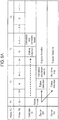
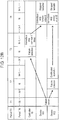
- FIG. 6A , FIG. 6B , and FIG. 6C each indicate chronological operation of controller 10 and motor control devices 20 in a case where multiaxial motor control system 100 for two shafts depicted in FIG. 4 has communication failure as described above.
- FIG. 6A indicates exemplary operation of each unit in a case where communication between controller 10 and first-shaft motor control device 201 is interrupted.
- FIG. 6B indicates exemplary operation of each unit in a case where communication between first-shaft motor control device 201 and second-shaft motor control device 202 is interrupted.
- FIG. 6C indicates exemplary operation of each unit in a case where communication between second-shaft motor control device 202 and controller 10 is interrupted.
- FIG. 6A to FIG. 6C each indicate mainly operation of controller 10 and motor control devices 20 relevant to emergency stop of motors 30 upon detection of communication failure.
- command update period TC of controller 10 and motor control/communication period TN of motor control devices 20
- command update period TC and motor control/communication period TN will be abbreviated as period TC and period TN, respectively, where appropriate.
- period TC is a reference period for transmission of a command signal.
- One period TC includes at least one period TN as a reference period for execution of motor control and communication in each motor control device 20.
- the present exemplary embodiment assumes that one period TC includes a plurality of periods TN.
- Period TC and period TN are preset before multiaxial motor control system 100 operates.
- Occurrence of communication failure and detection of the failure in controller 10 and motor control devices 20 can be included in identical period TC or periods TC different from each other, depending on relation between set values of these two periods. Operation from issue of a command signal by controller 10 at certain timing until drive and stop of motors 30 by motor control devices 20 for the plurality of shafts is executed in an identical period for motor control devices 20. Operation from occurrence of communication failure at certain timing until detection of the communication failure by communication controllers 14 in motor control devices 20 is also executed in an identical period for motor control devices 20.
- the identical period for motor control devices 20 is preferred to be identical motor control/communication period TN in the present exemplary embodiment.
- command update periods TC are specified as periods T1, T2, T3, and T4 in this order, and periods TC each include a predetermined number of periods TN.
- command update period TC corresponds to period T1.
- FIG. 6A to FIG. 6C indicate a flow of operation (processing) by controller 10 and motor control devices 20.
- Arrows of solid lines indicate a flow of processing directly relevant to operation for emergency stop of motors 30.
- Arrows of broken lines indicate a flow of processing not directly relevant to the operation for emergency stop of motors 30.
- the following practical examples assume that one or two processing is executed during each period TC, for better comprehension of the processing flow of controller 10 and motor control devices 20.
- first-shaft motor control device 201 and second-shaft motor control device 202 will be abbreviated as device 201 and device 202, respectively, where appropriate.
- Device 201 executes the immediate stop as indicated in FIG. 6A , in accordance with braking torque command Tb having braking torque value A preset in torque amount storage 44 in rotation controller 24.
- communication controller 14 outputs stop command Em1 indicating activation of the immediate stop, and rotation controller 24 executes the immediate stop function. Stop commands Em2 and Em3 indicate deactivation in this case.
- communication controller 14 outputs stop command Em2 indicating activation of the non-drive stop
- drive unit 25 executes the non-drive stop function.
- communication controller 14 outputs stop command Em3 indicating activation of the DB stop, to activate DB circuit 26 and apply the DB stop through dynamic braking.
- Braking torque value A for the immediate stop in exemplary operation 1A is preferably equal in amount to allowable maximum torque of multiaxial motor control system 100.
- the maximum torque value is set to minimize a stop distance of each of a plurality of drive shafts. Although torque less than the maximum torque leads to a longer stop distance, the torque amount can be determined in consideration of a stop position error between the plurality of shafts, heat generation by the DB circuits, and the like, to be necessary and sufficient.
- Exemplary operation 1A does not adopt the conventional technique of immediately disconnecting electrification to every motor 30 for the non-drive stop when communication failure occurs between controller 10 and device 201, but includes application of braking torque by the immediate stop function while at least one motor 30 keeps being electrified. Execution of failure handling operation according to exemplary operation 1A enables motors 30 for the plurality of shafts to stop quickly and safely.
- controller 10 detects communication failure and issues an immediate stop command for every motor 30.
- communication between controller 10 and device 201 has failure.
- multiaxial motor control system 100 is configured such that device 202 having detected failure disconnects electrification to motor 30, and device 201 not disconnecting electrification outputs drive voltage Vd according to braking torque command Tb preset in rotation controller 24, so as to stop motors 30.
- Multiaxial motor control system 100 is configured as described above and thus executes a procedure obtained by combining the immediate stop function and the non-drive stop function during failure. Accordingly, the shaft to which the immediate stop is applied stops quickly whereas the shaft to which the non-drive stop is applied gradually stops naturally. Particularly in a case where the gantry structure like control target mechanism 35 depicted in FIG. 4 is a control target, shaft X1 stops immediately whereas shaft X2 moves slowly to stop, for example. The entire control target comes to stop through such movement, so that stress applied to load 36 can be decreased in comparison to operation of immediately stopping both shaft X1 and shaft X2. Furthermore, one of the shafts stops immediately and can thus needs a shorter stop distance and shorter stop time in comparison to operation of naturally stopping all the shafts.
- the present exemplary embodiment exemplifies the case where there are provided the two motor control devices.
- motor control devices for a plurality of shafts the following configuration will be applicable. Specifically, when at least one motor control device detects failure in reception of a command signal, the at least one motor control device having detected the failure disconnects electrification to the motor. At least one of the motor control devices not disconnecting electrification to the motor outputs a torque command for braking torque preset in the rotation controller to stop the motor. Such a configuration achieves similar effects.
- communication controller 14 in device 201 normally receives a command from controller 10, and device 201 executes ordinary operation. Meanwhile, communication controller 14 in device 202 detects communication failure in response to the fact that "failure occurs".
- communication controller 14 outputs stop command Em2 indicating activation of the non-drive stop, and drive unit 25 executes the non-drive stop function.
- controller 10 detects communication failure and issues an immediate stop command for every motor 30. In this case, device 201 continues the ordinary operation whereas device 202 is kept in a non-drive stop state.
- a command signal issued from controller 10 for the immediate stop command to every motor 30 is received by device 201, and device 201 executes the immediate stop at braking torque value A.
- communication controller 14 in device 201 transmits stop command Em1 to rotation controller 24 or the like in accordance with the immediate stop command from controller 10.
- Torque processor 46 in device 201 then reads braking torque command Tb having braking torque value A from torque amount storage 44.
- the immediate stop function is executed in device 201 in this manner.
- the command signal from controller 10 is obviously not received by device 202 to be disregarded, and device 202 is kept in the non-drive stop state.
- Braking torque value A for the immediate stop in exemplary operation 1B is preferably equal in amount to allowable maximum torque of multiaxial motor control system 100.
- the maximum torque is set to minimize the stop distance of each of the drive shafts. Although torque less than the maximum torque leads to a longer stop distance, the torque amount can be determined in consideration of a stop position error between the plurality of shafts, heat generation by the DB circuits, and the like, to be necessary and sufficient.
- Exemplary operation 1B does not adopt the conventional technique of immediately disconnecting electrification to every motor 30 for the non-drive stop when communication failure occurs between device 201 and device 202, but includes application of braking torque by the immediate stop function while at least one motor 30 keeps being electrified. Execution of failure handling operation according to exemplary operation 1B enables motors 30 for the plurality of shafts to stop quickly and safely.
- multiaxial motor control system 100 is configured such that device 202 having detected failure disconnects electrification to motor 30, and device 201 not disconnecting electrification outputs drive voltage Vd corresponding to braking torque command Tb according to a command signal received normally from controller 10, so as to stop motors 30.
- Multiaxial motor control system 100 is also configured as described above and thus executes the procedure obtained by combining the immediate stop function and the non-drive stop function during failure, as in exemplary operation 1A. Stress applied to load 36 can thus be decreased in comparison to operation of immediately stopping both shaft X1 and shaft X2 in FIG. 4 . Furthermore, one of the shafts stops immediately and can thus needs a shorter stop distance and shorter stop time in comparison to operation of naturally stopping all the shafts.
- the present exemplary embodiment exemplifies the case where there are provided the two motor control devices.
- motor control devices for a plurality of shafts the following configuration will be applicable. Specifically, when at least one motor control device detects failure in reception of a command signal, the at least one motor control device having detected the failure disconnects electrification to the motor. When at least one of the motor control devices not cancelling electrification to the motor outputs a torque command for braking torque according to a command signal received normally from the controller to stop the motor. Such a configuration achieves similar effects.
- Exemplary operation 1C relates only to multiaxial motor control system 100 having ring connection.
- FIG. 6C indicates "failure occurs"
- controller 10 detects communication failure and issues an immediate stop command for every motor 30.
- Device 201 and device 202 each continue the ordinary operation.
- Braking torque value B for the immediate stop in exemplary operation 1C preferably has an amount obtained through dividing allowable maximum torque of multiaxial motor control system 100 by a number of shafts to be immediately stopped. The two shafts are immediately stopped in the present exemplary operation, so that braking torque value B preferably has an amount obtained through dividing the maximum torque by two as the number of the shafts. In other words, braking torque value B corresponds to a half of braking torque A mentioned above. Furthermore, two amounts of torque are more preferred to match each other to be an identical amount, so as to minimize the stop distances of the plurality of drive shafts. In consideration of safety and the like, braking torque can be set for each of the motor control devices such that a sum of the braking torque output from all the motor control devices is equal to or less than allowable maximum braking torque of the present multiaxial motor control system.
- Exemplary operation 1C also does not adopt the conventional technique of immediately disconnecting electrification to every motor 30 for the non-drive stop when communication failure occurs between device 202 and controller 10, but includes application of braking torque such that the maximum braking torque is dispersed to the respective shafts while every motor 30 keeps being electrified. Execution of failure handling operation according to exemplary operation 1C enables motors 30 for the plurality of shafts to stop quickly and safely.
- multiaxial motor control system 100 is configured such that, when controller 10 detects failure in reception of a response signal from device 202 to a command signal, all of device 201 and device 202 each output braking torque according to the command signal from controller 10 to stop motor 30.
- the above description relates to ring multiaxial motor control system 100 configured as depicted in FIG. 4 , but is applicable also to a line multiaxial motor control system.
- FIG. 7 is a block diagram depicting a configuration of line multiaxial motor control system 110 as another exemplary configuration of the multiaxial motor control system according to the first exemplary embodiment of the present invention.
- Line multiaxial motor control system 110 depicted in FIG. 7 is different from the motor control system depicted in FIG. 4 in that there is provided no communication line C connecting between controller 10 and second-shaft motor control device 202, and controller 10 and motor control devices 20 are connected to each other by means of bidirectional line connection via transmitting-receiving devices 17.
- the configuration to stop motors 30 during failure as described with reference to each of exemplary operation 1A to exemplary operation 1C is also applicable to this line connection system.
- control target mechanism 35 having the gantry structure as in FIG. 4 or FIG. 7 .
- the control target mechanism has only to include a plurality of drive shafts controlled by single controller 10.
- the control target mechanism can include a plurality of mechanically linked drive shafts as typically exemplified in the gantry structure, or can alternatively include a plurality of drive shafts not mechanically linked but controlled by single controller 10.
- the above description exemplifies the case of synchronously controlling the plurality of mechanically linked drive shafts.
- the plurality of drive shafts not mechanically linked can be controlled in a similar manner.
- controller 10 controls motor control devices for a plurality of shafts to be synchronously controlled, assuming that the shafts include one master shaft and remaining slave shafts.
- motor control devices 20 each include a storage device (e.g., a volatile or nonvolatile memory or a register) storing a preset parameter indicating whether motor control device 20 corresponds to the master shaft or one of the slave shafts.
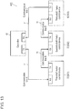
- FIG. 8 is a block diagram depicting a ring network configuration of multiaxial motor control system 200 for three shafts according to a second exemplary embodiment of the present invention.
- multiaxial motor control system 200 configures a triaxial motor control system including controller 10 and three motor control devices 20 connected to form a ring shape.
- additional motor control device 20 is connected in series between two motor control devices 20 depicted in FIG. 1 .
- Controller 10 and motor control devices 20 are each configured as in internal configurations depicted in FIG. 4 and FIG. 5 .
- a portion identical or corresponding to a portion according to the first exemplary embodiment will be denoted by an identical reference mark and will not be described partially.
- second-shaft motor control device 202 and third-shaft motor control device 203 have network connection via communication line 11 specified as communication line D
- third-shaft motor control device 203 and controller 10 have network connection via communication line 11 specified as communication line C.
- Multiaxial motor control system 200 thus configured will be described next in terms of operation and effects.
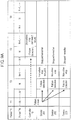
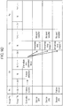
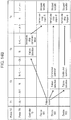
- FIG. 9A , FIG. 9B , FIG. 9C , and FIG. 9D each indicate chronological operation of controller 10 and motor control devices 20 in a case where multiaxial motor control system 200 for three shafts depicted in FIG. 8 has communication failure as described in the first exemplary embodiment.
- FIG. 9A indicates exemplary operation of each unit in a case where communication between controller 10 and first-shaft motor control device 201 is interrupted.
- FIG. 9B indicates exemplary operation of each unit in a case where communication between first-shaft motor control device 201 and second-shaft motor control device 202 is interrupted.
- FIG. 9A , FIG. 9B , FIG. 9C , and FIG. 9D each indicate chronological operation of controller 10 and motor control devices 20 in a case where multiaxial motor control system 200 for three shafts depicted in FIG. 8 has communication failure as described in the first exemplary embodiment.
- FIG. 9A indicates exemplary operation of each unit in a case where communication between controller 10 and first-shaft motor control device 201 is interrupted.
- FIG. 9C indicates exemplary operation of each unit in a case where communication between second-shaft motor control device 202 and third-shaft motor control device 203 is interrupted.
- FIG. 9D indicates exemplary operation of each unit in a case where communication between third-shaft motor control device 203 and controller 10 is interrupted.
- FIG. 9A to FIG. 9D each indicate mainly operation of controller 10 and motor control devices 20 relevant to the emergency stop of motors 30 upon detection of communication failure.
- the motor control devices will be specified appropriately by being identified as device 201, device 202, and device 203, while each of the motor control devices will generically be called motor control device 20.
- Device 201 executes immediate stop as indicated in FIG. 9A , in accordance with braking torque command Tb having braking torque value A' preset in torque amount storage 44 in rotation controller 24.
- communication controller 14 outputs stop command Em1 indicating activation of the immediate stop, and rotation controller 24 executes the immediate stop function. Stop commands Em2 and Em3 indicate deactivation in this case.
- communication controller 14 outputs stop command Em2 indicating activation of the non-drive stop, and drive unit 25 executes the non-drive stop function.
- stop command Em3 indicating activation of DB stop
- DB circuit 26 activates DB stop through dynamic braking.
- Braking torque value A' for the immediate stop in exemplary operation 2A is preferably equal in amount to allowable maximum torque of multiaxial motor control system 200.
- the maximum torque value is set to minimize a stop distance of each of a plurality of drive shafts. Although torque less than the maximum torque leads to a longer stop distance, the torque amount can be determined in consideration of a stop position error between the plurality of shafts, heat generation by the DB circuits, and the like, to be necessary and sufficient.
- Exemplary operation 2A does not adopt the conventional technique of immediately disconnecting electrification to every motor 30 for the non-drive stop when communication failure occurs between controller 10 and device 201, but includes application of braking torque by the immediate stop function while at least one motor 30 keeps being electrified. Execution of failure handling operation according to exemplary operation 2A enables motors 30 for the plurality of shafts to stop quickly and safely.
- controller 10 detects communication failure and issues an immediate stop command for every motor 30.
- communication between controller 10 and device 201 has failure.
- multiaxial motor control system 200 is configured such that each of device 202 and device 203 having detected failure disconnects electrification to motor 30, and device 201 not disconnecting electrification outputs drive voltage Vd according to braking torque command Tb preset in rotation controller 24, so as to stop motors 30.
- stress applied to load 36 can be decreased in comparison to operation of immediately stopping both shaft X1 and shaft X2 in FIG. 4 . Furthermore, at least one of the shafts stops immediately and can thus needs a shorter stop distance and shorter stop time in comparison to operation of naturally stopping all the shafts.
- the present exemplary embodiment exemplifies the case where there are provided the three motor control devices.
- motor control devices for a plurality of shafts the following configuration will be applicable. Specifically, when at least one motor control device detects failure in reception of a command signal, the at least one motor control device having detected the failure disconnects electrification to the motor. At least one of the motor control devices not disconnecting electrification to the motor outputs a torque command for braking torque preset in the rotation controller to stop the motor. Such a configuration achieves similar effects.
- communication controller 14 in device 201 normally receives a command from controller 10, and device 201 executes ordinary operation. Meanwhile, communication controller 14 in each of device 202 and device 203 detects communication failure in response to the fact that "failure occurs".
- communication controller 14 outputs stop command Em2 indicating activation of the non-drive stop, and drive unit 25 executes the non-drive stop function.
- controller 10 detects communication failure and issues an immediate stop command for every motor 30.
- device 201 continues the ordinary operation whereas device 202 and device 203 are kept in the non-drive stop state.
- a command signal issued from controller 10 for the immediate stop command to every motor 30 is received by device 201, and device 201 executes immediate stop at braking torque value A'.
- communication controller 14 in device 201 transmits stop command Em1 to rotation controller 24 or the like in accordance with the immediate stop command from controller 10.
- Torque processor 46 in device 201 then reads braking torque command Tb having braking torque value A' from torque amount storage 44.
- the immediate stop function is executed in device 201 in this manner.
- the command signal from controller 10 is obviously not received by device 202 and device 203 to be disregarded, and device 202 and device 203 are kept in the non-drive stop state.
- Braking torque value A' for the immediate stop in exemplary operation 2B is preferably equal in amount to allowable maximum torque of multiaxial motor control system 200.
- the maximum torque is set to minimize the stop distance of each of the drive shafts. Although torque less than the maximum torque leads to a longer stop distance, the torque amount can be determined in consideration of a stop position error between the plurality of shafts, heat generation by the DB circuits, and the like, to be necessary and sufficient.
- Exemplary operation 2B does not adopt the conventional technique of immediately disconnecting electrification to every motor 30 for the non-drive stop when communication failure occurs between device 201 and device 202, but includes application of braking torque by the immediate stop function while at least one motor 30 keeps being electrified. Execution of failure handling operation according to exemplary operation 2B enables motors 30 for the plurality of shafts to stop quickly and safely.
- multiaxial motor control system 200 is configured such that each of device 202 and device 203 having detected failure disconnects electrification to motor 30, and device 201 not disconnecting electrification outputs drive voltage Vd corresponding to braking torque command Tb according to a command signal received normally from controller 10, so as to stop motors 30.
- Multiaxial motor control system 200 is also configured as described above and thus executes the procedure obtained by combining the immediate stop function and the non-drive stop function during failure, as in exemplary operation 1B. Stress applied to load 36 can thus be decreased in comparison to operation of immediately stopping both shaft X1 and shaft X2 in FIG. 4 . Furthermore, one of the shafts stops immediately and can thus needs a shorter stop distance and shorter stop time in comparison to operation of naturally stopping all the shafts.
- the present exemplary embodiment exemplifies the case where there are provided the two motor control devices.
- motor control devices for a plurality of shafts the following configuration will be applicable. Specifically, when at least one motor control device detects failure in reception of a command signal, the at least one motor control device having detected the failure disconnects electrification to the motor. When at least one of the motor control devices not cancelling electrification to the motor outputs a torque command for braking torque according to a command signal received normally from the controller to stop the motor. Such a configuration achieves similar effects.
- communication controller 14 in each of device 201 and device 202 normally receives a command from controller 10, and device 201 and device 202 execute the ordinary operation. Meanwhile, communication controller 14 in device 203 detects communication failure in response to the fact that "failure occurs".
- communication controller 14 outputs stop command Em2 indicating activation of the non-drive stop, and drive unit 25 executes the non-drive stop function.
- controller 10 detects communication failure and issues an immediate stop command for every motor 30. In this case, device 201 and device 202 continue the ordinary operation whereas device 203 is kept in the non-drive stop state.
- a command signal issued from controller 10 for the immediate stop command to every motor 30 is received by each of device 201 and device 202, and device 201 and device 202 each execute the immediate stop at braking torque value C.
- communication controller 14 in each of device 201 and device 202 transmits stop command Em1 to rotation controller 24 or the like in accordance with the immediate stop command from controller 10.
- Torque processor 46 in each of device 201 and device 202 then reads braking torque command Tb having braking torque value C from torque amount storage 44.
- the immediate stop function is executed in each of device 201 and device 202 in this manner.
- the command signal from controller 10 is obviously not received by device 203 to be disregarded, and device 203 is kept in the non-drive stop state.
- Braking torque value C for the immediate stop in exemplary operation 2C preferably has an amount obtained through dividing allowable maximum torque of multiaxial motor control system 200 by a number of shafts (two in the present practical example) to be immediately stopped.
- the two shafts are immediately stopped in the present exemplary operation, so that braking torque value C preferably has an amount obtained through dividing the maximum torque by two as the number of the shafts.
- braking torque value C corresponds to a half of braking torque A' mentioned above.
- two amounts of torque are more preferred to match each other to be an identical amount, so as to minimize the stop distances of the plurality of drive shafts.
- braking torque can be set for each of the motor control devices such that a sum of the braking torque output from all the motor control devices is equal to or less than allowable maximum braking torque of the present multiaxial motor control system.
- Exemplary operation 2C does not adopt the conventional technique of immediately disconnecting electrification to every motor 30 for the non-drive stop when communication failure occurs between device 202 and device 203, but includes application of braking torque by the immediate stop function while at least one motor 30 keeps being electrified. Execution of failure handling operation according to exemplary operation 2C enables motors 30 for the plurality of shafts to stop quickly and safely.
- multiaxial motor control system 200 is configured such that device 203 having detected failure disconnects electrification to motor 30, and each of device 201 device 202 not disconnecting electrification outputs drive voltage Vd corresponding to braking torque command Tb according to a command signal received normally from controller 10, so as to stop motors 30.
- Multiaxial motor control system 200 is also configured as described above and thus executes the procedure obtained by combining the immediate stop function and the non-drive stop function during failure, as in exemplary operation 1B and exemplary operation 2B. Stress applied to load 36 can thus be decreased in comparison to operation of immediately stopping both shaft X1 and shaft X2 in FIG. 4 . Furthermore, at least one of the shafts stops immediately and can thus needs a shorter stop distance and shorter stop time in comparison to operation of naturally stopping all the shafts.
- the present exemplary embodiment exemplifies the case where there are provided the three motor control devices.
- motor control devices for a plurality of shafts the following configuration will be applicable. Specifically, when at least one motor control device detects failure in reception of a command signal, the at least one motor control device having detected the failure disconnects electrification to the motor. When at least one of the motor control devices not cancelling electrification to the motor outputs a torque command for braking torque according to a command signal received normally from the controller to stop the motor. Such a configuration achieves similar effects.
- Exemplary operation 2D relates only to multiaxial motor control system 200 having ring connection.
- controller 10 detects communication failure and issues an immediate stop command for every motor 30.
- motor control devices 20 continue the ordinary operation.
- Braking torque value B' for the immediate stop in exemplary operation 2D preferably has an amount obtained through dividing allowable maximum torque of multiaxial motor control system 200 by the number of shafts to be immediately stopped.
- the three shafts are immediately stopped in the present exemplary operation, so that braking torque value B' preferably has an amount obtained through dividing the maximum torque by three as the number of the shafts.
- braking torque value B' corresponds to one third of braking torque A mentioned above.
- three amounts of torque are more preferred to match one another to be an identical amount, so as to minimize the stop distances of the plurality of drive shafts.
- braking torque can be set for each motor control device 20 such that a sum of the braking torque output from all motor control devices 20 is equal to or less than allowable maximum braking torque of multiaxial motor control system 200.
- Exemplary operation 2D also does not adopt the conventional technique of immediately disconnecting electrification to every motor 30 for the non-drive stop when communication failure occurs between device 203 and controller 10, but includes application of braking torque such that the maximum braking torque is dispersed to the respective shafts while every motor 30 keeps being electrified. Execution of failure handling operation according to exemplary operation 2D enables motors 30 for the plurality of shafts to stop quickly and safely.
- multiaxial motor control system 200 is configured such that, when controller 10 detects failure in reception of a response signal from device 203 to a command signal, all of device 201, device 202, and device 203 each output braking torque according to the command signal from controller 10 to stop motor 30.
- a triaxial motor control system (not depicted) having line connection can be configured such that the configuration depicted in FIG. 2 is applied with difference between the biaxial motor control system having ring connection depicted in FIG. 1 and the triaxial motor control system having ring connection depicted in FIG. 7 .
- the configuration described with reference to each of exemplary operation 2A to exemplary operation 2D is also applicable to such a line configuration.
- a method of emergently stopping motors 30 adopted for multiaxial motor control system 100, 200 for two or three shafts described above is applicable also to a multiaxial motor control system for four or more shafts corresponding to motors 30 and controlled synchronously.
- Addition of one motor control device 20 corresponding to second-shaft motor control device 202 added for increase from the two shafts to the three shafts is required every time one shaft is added.
- Added motor control device 20 needs to be configured to execute immediate stop, non-drive stop, or immediate stop after elapse of predetermined time from the end of continuous operation, similarly to adjacent motor control devices 20.
- FIG. 10 is a block diagram depicting a ring network configuration of multiaxial motor control system 300 for two shafts, having ring connection, according to a third exemplary embodiment of the present invention.
- FIG. 11 is a block diagram depicting a detailed exemplary configuration of motor control device 50 according to the third exemplary embodiment of the present invention.
- multiaxial motor control system 300 configures a triaxial motor control system including controller 10 and two motor control devices 50 connected to form a ring shape.
- multiaxial motor control system 300 according to the present exemplary embodiment includes motor control devices 50 in place of motor control devices 20 of the first exemplary embodiment.
- Motor control devices 20 according to the first exemplary embodiment are each configured to selectively adopt the above three functions for stop of driving the motor upon detection of communication failure.
- motor control devices 50 according to the present exemplary embodiment are each configured to stop driving the motor by adopting only the immediate stop function. Communication controller 14 thus notifies rotation controller 24 of only stop command Em1.
- Each motor control device 50 does not include any DB circuit, and drive unit 55 in motor control device 50 includes only drive output generator 51.
- a constituent element same as a constituent element according to the first exemplary embodiment will be denoted by an identical reference mark and will not be described in detail repeatedly.
- Multiaxial motor control system 300 thus configured will be described next in terms of operation and effects.
- FIG. 12A and FIG. 12B each indicate chronological operation of controller 10 and motor control devices 50 in a case where multiaxial motor control system 300 for two shafts depicted in FIG. 10 has communication failure as described in the first exemplary embodiment.
- FIG. 12A indicates exemplary operation of each unit in a case where communication between controller 10 and first-shaft motor control device 501 is interrupted.
- FIG. 12B indicates exemplary operation of each unit in a case where communication between first-shaft motor control device 501 and second-shaft motor control device 502 is interrupted. Operation during communication interruption between second-shaft motor control device 502 and controller 10 is similar to exemplary operation 1C described with reference to FIG.
- FIG. 12A to FIG. 12B each indicate mainly operation of controller 10 and motor control devices 50 relevant to emergency stop of motors 30 upon detection of communication failure.
- the motor control devices will be specified appropriately by being identified as device 501 and device 502, while each of the motor control devices will generically be called motor control device 50.
- device 501 and device 502 subsequently each execute operation with switching to individual control for the own device in accordance with the latest command from controller 10 received most recently in the normal communication state (hereinafter, called continuous operation).
- the continuous operation is executed for time to be described later.
- communication between controller 10 and device 501 has failure.
- a command signal from controller 10 obviously fails to reach each of device 501 and device 502.
- device 501 and device 502 each execute the continuous operation in accordance with individual control for the own device in this case.
- the time for the continuous operation is preset in device 501 and device 502.
- the time for the continuous operation is set in consideration of period TC and period TN required due to speed of communication among controller 10, device 501, and device 502, processing speed of controller 10, and the like. Furthermore, the signal from controller 10 for the immediate stop command will not reach each of device 501 and device 502 as described above.
- Motor control devices 50 each have preset time from start of the continuous operation until motor control device 50 outputs braking torque set in rotation controller 24 and motor 30 stops as predetermined time for the continuous operation.
- This predetermined time is set to be equal to k (k is a natural number) times of command update period TC as the reference period for transmission of a command signal by controller 10.
- device 501 and device 502 each execute the immediate stop as indicated in FIG. 12A , not in accordance with a command received from controller 10 but in accordance with braking torque command Tb having braking torque value B preset in torque amount storage 44 in rotation controller 24.
- communication controller 14 outputs stop command Em1 indicating activation of the immediate stop, and rotation controller 24 executes the immediate stop function.
- Braking torque value B for the immediate stop in exemplary operation 3A preferably has an amount obtained through dividing allowable maximum torque of multiaxial motor control system 300 by a number of shafts to be immediately stopped.
- braking torque value B preferably has an amount obtained through dividing the maximum torque by two as the number of the shafts.
- braking torque value B corresponds to a half of the maximum braking torque value.
- two amounts of torque are more preferred to match each other to be an identical amount, so as to minimize the stop distances of the plurality of drive shafts.
- braking torque can be set for each of the motor control devices such that a sum of the braking torque output from all the motor control devices is equal to or less than allowable maximum braking torque of the present multiaxial motor control system.
- Exemplary operation 3A also does not adopt the conventional technique of immediately disconnecting electrification to every motor 30 for non-drive stop when communication failure occurs between controller 10 and device 501, but includes application of braking torque such that the maximum braking torque is dispersed to the respective shafts while every motor 30 keeps being electrified. Execution of failure handling operation according to exemplary operation 3A enables motors 30 for the plurality of shafts to stop quickly and safely.
- each of device 501 and device 502 having detected failure outputs driving torque according to a command signal received normally before the failure detection to execute the continuous operation of the corresponding motor.
- all of device 501 and device 502 for control of the plurality of shafts each output braking torque preset in the rotation controller to stop the corresponding motor.
- the present exemplary embodiment exemplifies the case where there are provided the two motor control devices.
- motor control devices for a plurality of shafts the following configuration will be applicable.
- the at least one motor control device detects failure in reception of a command signal
- the at least one motor control device having detected the failure outputs driving torque according to a command signal received normally before the detection of the failure to execute the continuous operation of the motor.
- all of the motor control devices for control of the plurality of shafts each output braking torque preset in the rotation controller to stop the corresponding motor.
- communication controller 14 in device 501 normally receives a command from controller 10, and device 501 executes ordinary operation. Meanwhile, communication controller 14 in device 502 detects communication failure in response to the fact that "failure occurs".
- device 502 subsequently switches to individual control for the own device and executes the continuous operation.
- the continuous operation is executed for time to be described later.
- controller 10 detects communication failure and issues an immediate stop command for every motor 30. In this case, device 501 continues the ordinary operation whereas device 502 executes the continuous operation.
- the time for the continuous operation is preset in device 502.
- the time for the continuous operation is set in consideration of period TC and period TN required due to speed of communication among controller 10, device 501, and device 502, processing speed of controller 10, and the like.
- the time for the continuous operation on this assumption lasts from start of the continuous operation until each of device 501 and device 502 receives a command signal and executes the immediate stop.
- motor control devices 50 each have preset time from start of the continuous operation until motor control device 50 outputs braking torque set in rotation controller 24 and motor 30 stops as predetermined time for the continuous operation.
- This predetermined time is set to be equal to k (k is a natural number) times of command update period TC as the reference period for transmission of a command signal by controller 10.
- Braking torque value B for the immediate stop in exemplary operation 3B preferably has an amount obtained through dividing allowable maximum torque of multiaxial motor control system 300 by the number of shafts to be immediately stopped. The two shafts are immediately stopped in the present exemplary operation, so that braking torque value B preferably has an amount obtained through dividing the maximum torque by two as the number of the shafts.
- braking torque value B corresponds to a half of the maximum braking torque value. Furthermore, two amounts of torque are more preferred to match each other to be an identical amount, so as to minimize the stop distances of the plurality of drive shafts. In consideration of safety and the like, braking torque can be set for each of the motor control devices such that a sum of the braking torque output from all the motor control devices is equal to or less than allowable maximum braking torque of the present multiaxial motor control system.
- Exemplary operation 3B also does not adopt the conventional technique of immediately disconnecting electrification to every motor 30 for the non-drive stop when communication failure occurs between device 501 and device 502, but includes application of braking torque such that the maximum braking torque is dispersed to the respective shafts while every motor 30 keeps being electrified. Execution of failure handling operation according to exemplary operation 3B enables motors 30 for the plurality of shafts to stop quickly and safely.
- device 502 having detected failure outputs driving torque according to a command signal received normally before the failure detection to execute the continuous operation of motor 30. After predetermined time from start of the continuous operation, device 502 outputs braking torque preset in the rotation controller to stop the motor.
- device 501 not executing the continuous operation outputs braking torque according to a command signal received normally from controller 10 to stop the motor.
- the present exemplary embodiment exemplifies the case where there are provided the two motor control devices.
- motor control devices for a plurality of shafts the following configuration will be applicable.
- the at least one motor control device detects failure in reception of a command signal
- the at least one motor control device having detected the failure outputs driving torque according to a command signal received normally before the detection of the failure to execute the continuous operation of the motor.
- at least one of the motor control devices having executed the continuous operation outputs braking torque preset in the torque controller to stop the motor.
- at least one of the motor control devices not executing the continuous operation outputs braking torque according to a command signal received normally from the controller to stop the motor.
- Such a configuration achieves similar effects.
- FIG. 13 is a block diagram depicting a ring network configuration of multiaxial motor control system 400 for three shafts according to a fourth exemplary embodiment of the present invention.
- multiaxial motor control system 400 configures a triaxial motor control system including controller 10 and three motor control devices 50 connected to form a ring shape.
- additional motor control device 50 is connected in series between two motor control devices 50 depicted in FIG. 10 .
- Motor control devices 50 are each configured as in an internal configuration depicted in FIG. 11 .
- a portion identical or corresponding to a portion according to the third exemplary embodiment will be denoted by an identical reference mark and will not be described partially.
- second-shaft motor control device 502 and third-shaft motor control device 503 have network connection via communication line 11 specified as communication line D
- third-shaft motor control device 503 and controller 10 have network connection via communication line 11 specified as communication line C.
- Multiaxial motor control system 400 thus configured will be described next in terms of operation and effects.
- FIG. 14A , FIG. 14B , and FIG. 14C each indicate chronological operation of controller 10 and motor control devices 50 in a case where multiaxial motor control system 400 for three shafts depicted in FIG. 13 has communication failure as described in the first exemplary embodiment.
- FIG. 14A indicates exemplary operation of each unit in a case where communication between controller 10 and first-shaft motor control device 501 is interrupted.
- FIG. 14B indicates exemplary operation of each unit in a case where communication between first-shaft motor control device 501 and second-shaft motor control device 502 is interrupted.
- FIG. 14A , FIG. 14B , and FIG. 14C each indicate chronological operation of controller 10 and motor control devices 50 in a case where multiaxial motor control system 400 for three shafts depicted in FIG. 13 has communication failure as described in the first exemplary embodiment.
- FIG. 14A indicates exemplary operation of each unit in a case where communication between controller 10 and first-shaft motor control device 501 is interrupted.
- FIG. 14B indicates exemplary operation of each unit in
- FIG. 14C indicates exemplary operation of each unit in a case where communication between second-shaft motor control device 502 and third-shaft motor control device 503 is interrupted. Operation during communication failure between third-shaft motor control device 503 and controller 10 is similar to exemplary operation 2D described with reference to FIG. 9D in the second exemplary embodiment, and will not be described in detail repeatedly.
- FIG. 14A to FIG. 14C each indicate mainly operation of controller 10 and motor control devices 50 relevant to emergency stop of motors 30 upon detection of communication failure.
- the motor control devices will be specified appropriately by being identified as device 501, device 502, and device 503, while each of the motor control devices will generically be called motor control device 50.
- exemplary operation 4A device 501, device 502, and device 503 subsequently each execute operation with switching to individual control for the own device in accordance with the latest command from controller 10 received most recently in the normal communication state (hereinafter, called continuous operation).
- the continuous operation is executed for time preset in each motor control device 50 as in exemplary operation 3A for the biaxial motor control system. The time will not be described in detail repeatedly.
- communication between controller 10 and device 501 has failure.
- a command signal from controller 10 obviously fails to reach each of device 501, device 502, and device 503.
- device 501, device 502, and device 503 each execute the continuous operation in accordance with individual control for the own device in this case.
- device 501, device 502, and device 503 each execute immediate stop as indicated in FIG. 14A , not in accordance with a command received from controller 10 but in accordance with braking torque command Tb having braking torque value B' preset in torque amount storage 44 in rotation controller 24.
- communication controller 14 outputs stop command Em1 indicating activation of the immediate stop, and rotation controller 24 executes the immediate stop function.
- Braking torque value B' for the immediate stop in exemplary operation 4A preferably has an amount obtained through dividing allowable maximum torque of multiaxial motor control system 400 by a number of shafts to be immediately stopped.
- the three shafts are immediately stopped in the present exemplary operation, so that braking torque value B' preferably has an amount obtained through dividing the maximum torque by three as the number of the shafts.
- braking torque value B' corresponds to one third of the maximum braking torque value.
- three amounts of torque are more preferred to match one another to be an identical amount, so as to minimize the stop distances of the plurality of drive shafts.
- braking torque can be set for each of the motor control devices such that a sum of the braking torque output from all the motor control devices is equal to or less than allowable maximum braking torque of the present multiaxial motor control system.
- Exemplary operation 4A also does not adopt the conventional technique of immediately disconnecting electrification to every motor 30 for the non-drive stop when communication failure occurs between controller 10 and device 501, but includes application of braking torque such that the maximum braking torque is dispersed to the respective shafts while every motor 30 keeps being electrified. Execution of failure handling operation according to exemplary operation 4A enables motors 30 for the plurality of shafts to stop quickly and safely.
- each of device 501, device 502, and device 503 having detected failure outputs driving torque according to a command signal received normally before the failure detection to execute the continuous operation of the corresponding motor.
- all of device 501, device 502, and device 503 for control of the plurality of shafts each output braking torque preset in the rotation controller to stop the corresponding motor.
- the present exemplary embodiment exemplifies the case where there are provided the three motor control devices.
- motor control devices for a plurality of shafts the following configuration will be applicable.
- the at least one motor control device detects failure in reception of a command signal
- the at least one motor control device having detected the failure outputs driving torque according to a command signal received normally before the detection of the failure to execute the continuous operation of the motor.
- all of the motor control devices for control of the plurality of shafts each output braking torque preset in the rotation controller to stop the corresponding motor.
- communication controller 14 in device 501 normally receives a command from controller 10, and device 501 executes ordinary operation. Meanwhile, communication controller 14 in each of device 502 and device 503 detects communication failure in response to the fact that "failure occurs".
- each of device 502 and device 503 subsequently switches to individual control for the own device and executes the continuous operation.
- the continuous operation is executed for time similar to the time according to exemplary operation 3B for the biaxial motor control system, and will not be described in detail repeatedly.
- device 501 continues the ordinary operation whereas device 502 and device 503 execute the continuous operation.
- Braking torque value B' for the immediate stop in exemplary operation 4B preferably has an amount obtained through dividing allowable maximum torque of multiaxial motor control system 400 by the number of shafts to be immediately stopped. The three shafts are immediately stopped in the present exemplary operation, so that braking torque value B' preferably has an amount obtained through dividing the maximum torque by three as the number of the shafts.
- braking torque value B' corresponds to one third of the maximum braking torque value. Furthermore, three amounts of torque are more preferred to match one another to be an identical amount, so as to minimize the stop distances of the plurality of drive shafts. In consideration of safety and the like, braking torque can be set for each of the motor control devices such that a sum of the braking torque output from all the motor control devices is equal to or less than allowable maximum braking torque of the present multiaxial motor control system.
- Exemplary operation 4B also does not adopt the conventional technique of immediately disconnecting electrification to every motor 30 for the non-drive stop when communication failure occurs between device 501 and device 502, but includes application of braking torque such that the maximum braking torque is dispersed to the respective shafts while every motor 30 keeps being electrified. Execution of failure handling operation according to exemplary operation 4B enables motors 30 for the plurality of shafts to stop quickly and safely.
- each of device 502 and device 503 having detected failure outputs driving torque according to a command signal received normally before the failure detection to execute the continuous operation of motor 30.
- each of device 502 and device 503 outputs braking torque preset in the rotation controller to stop the corresponding motor.
- device 501 not executing the continuous operation outputs braking torque according to a command signal received normally from controller 10 to stop the motor.
- the present exemplary embodiment exemplifies the case where there are provided the two motor control devices.
- motor control devices for a plurality of shafts the following configuration will be applicable.
- the at least one motor control device detects failure in reception of a command signal
- the at least one motor control device having detected the failure outputs driving torque according to a command signal received normally before the detection of the failure to execute the continuous operation of the motor.
- at least one of the motor control devices having executed the continuous operation outputs braking torque preset in the torque controller to stop the motor.
- at least one of the motor control devices not executing the continuous operation outputs braking torque according to a command signal received normally from the controller to stop the motor.
- Such a configuration achieves similar effects.
- communication controller 14 in each of device 501 and device 502 normally receives a command from controller 10, and device 501 and device 502 execute the ordinary operation. Meanwhile, communication controller 14 in device 503 detects communication failure in response to the fact that "failure occurs".
- device 503 subsequently switches to individual control for the own device and executes the continuous operation.
- the continuous operation is executed for time similar to the time according to exemplary operation 3B for the biaxial motor control system, and will not be described in detail repeatedly.
- device 501 and device 502 each continue the ordinary operation whereas device 503 executes the continuous operation.
- Braking torque value B' for the immediate stop in exemplary operation 4C preferably has an amount obtained through dividing allowable maximum torque of multiaxial motor control system 400 by the number of shafts to be immediately stopped. The three shafts are immediately stopped in the present exemplary operation, so that braking torque value B' preferably has an amount obtained through dividing the maximum torque by three as the number of the shafts.
- braking torque value B' corresponds to one third of the maximum braking torque value. Furthermore, three amounts of torque are more preferred to match one another to be an identical amount, so as to minimize the stop distances of the plurality of drive shafts. In consideration of safety and the like, braking torque can be set for each of the motor control devices such that a sum of the braking torque output from all the motor control devices is equal to or less than allowable maximum braking torque of the present multiaxial motor control system.
- Exemplary operation 4C also does not adopt the conventional technique of immediately disconnecting electrification to every motor 30 for the non-drive stop when communication failure occurs between device 502 and device 503, but includes application of braking torque while every motor 30 keeps being electrified. Execution of failure handling operation according to exemplary operation 4C enables motors 30 for the plurality of shafts to stop quickly and safely.
- device 503 having detected failure outputs driving torque according to a command signal received normally before the failure detection to execute the continuous operation of motor 30. After predetermined time from start of the continuous operation, device 503 outputs braking torque preset in the rotation controller to stop the motor.
- each of device 501 and device 502 not executing the continuous operation outputs braking torque according to a command signal received normally from controller 10 to stop the corresponding motor.
- the present exemplary embodiment exemplifies the case where there are provided the two motor control devices.
- motor control devices for a plurality of shafts the following configuration will be applicable.
- the at least one motor control device detects failure in reception of a command signal
- the at least one motor control device having detected the failure outputs driving torque according to a command signal received normally before the detection of the failure to execute the continuous operation of the motor.
- at least one of the motor control devices having executed the continuous operation outputs braking torque preset in the torque controller to stop the motor.
- at least one of the motor control devices not executing the continuous operation outputs braking torque according to a command signal received normally from the controller to stop the motor.
- Such a configuration achieves similar effects.
- FIG. 15 is a block diagram depicting a ring network configuration of multiaxial motor control system 500 for two shafts according to a fifth exemplary embodiment of the present invention.
- Multiaxial motor control system 500 depicted in FIG. 15 has ring connection and includes motors for two shafts to be controlled synchronously by motor control devices 20, and three asynchronous motor control devices 70.
- three asynchronous motor control devices 70 are configured to execute control not in synchronization with first and second shafts and are connected in series to be each interposed between controller 10, first-shaft motor control device 201, and second-shaft motor control device 202 depicted in FIG. 1 .
- Asynchronous motor control devices 70 are similar to motor control devices 20 but are not configured to execute synchronous control of driving or stopping in the present invention.
- a portion identical or corresponding to a portion according to the first exemplary embodiment will be denoted by an identical reference mark and will not be described partially.
- Controller 10 motor control device 70, motor control device 201, motor control device 70, motor control device 202, motor control device 70, and controller 10 have network connection in the mentioned order via communication lines 11 specified as communication line E, communication line F, communication line G, communication line H, communication line I, and communication line J, respectively.
- Multiaxial motor control system 500 thus configured initially has communication failure at communication line E, communication line F, or motor control device 70 disposed between communication line E and communication line F.
- motor control device 201 and motor control device 202 according to the present exemplary embodiment, configured to execute synchronous control, execute emergency stop operation as in the case of detection of communication failure generated at communication line A in the first exemplary embodiment.
- Communication failure occurs at communication line G, communication line H, or motor control device 70 disposed between communication line G and communication line H.
- motor control device 201 and motor control device 202 configured to execute synchronous control, execute emergency stop operation as in the case of detection of communication failure generated at communication line B in the first exemplary embodiment.
- communication failure occurs at communication line I, communication line J, or motor control device 70 disposed between communication line I and communication line J.
- motor control device 201 and motor control device 202 configured to execute synchronous control, execute emergency stop operation as in the case of detection of communication failure generated at communication line C in the first exemplary embodiment.
- asynchronous motor control devices 70 are removed, or there is further provided an asynchronous motor control device in addition to asynchronous motor control devices 70. Also in such a case, motor control device 201 and motor control device 202 configured to execute synchronous control can obviously execute emergency stop operation as in the first exemplary embodiment by appropriately adopting that described above.
- a multiaxial motor control system for three or more shafts corresponding to motors and controlled synchronously also includes a motor control device configured not to execute synchronous control. Also in such a case, emergency stop operation can obviously be executed as in the second exemplary embodiment or the fourth exemplary embodiment by appropriately adopting that described above.
- emergency stop operation can be executed as in the first exemplary embodiment.
- the multiaxial motor control system is configured to control the motor control devices for a plurality of shafts having network connection with the controller.
- the motor control devices When the motor control devices are controlled in such a configuration, communication failure may occur due to break or the like of a communication line or malfunction of any device on the network and each of the motor control devices may fail to receive a command signal from the controller.
- the present invention enables motors for the plurality of shafts to be stopped safely and quickly by application of braking torque even during such communication failure, while at least one of the motors keeps being electrified.
Landscapes
- Engineering & Computer Science (AREA)
- Power Engineering (AREA)
- General Physics & Mathematics (AREA)
- Human Computer Interaction (AREA)
- Manufacturing & Machinery (AREA)
- Physics & Mathematics (AREA)
- Automation & Control Theory (AREA)
- Microelectronics & Electronic Packaging (AREA)
- Computer Hardware Design (AREA)
- Control Of Multiple Motors (AREA)
- Stopping Of Electric Motors (AREA)
- Control Of Electric Motors In General (AREA)
- Variable-Direction Aerials And Aerial Arrays (AREA)
Applications Claiming Priority (2)
| Application Number | Priority Date | Filing Date | Title |
|---|---|---|---|
| JP2016050331 | 2016-03-15 | ||
| PCT/JP2017/009125 WO2017159472A1 (ja) | 2016-03-15 | 2017-03-08 | 複数軸モータ制御システム |
Publications (3)
| Publication Number | Publication Date |
|---|---|
| EP3432464A1 true EP3432464A1 (de) | 2019-01-23 |
| EP3432464A4 EP3432464A4 (de) | 2019-04-24 |
| EP3432464B1 EP3432464B1 (de) | 2022-12-21 |
Family
ID=59851265
Family Applications (1)
| Application Number | Title | Priority Date | Filing Date |
|---|---|---|---|
| EP17766473.7A Active EP3432464B1 (de) | 2016-03-15 | 2017-03-08 | Mehrachsiges motorsteuerungssystem |
Country Status (7)
| Country | Link |
|---|---|
| US (1) | US11329577B2 (de) |
| EP (1) | EP3432464B1 (de) |
| JP (1) | JP7029601B2 (de) |
| KR (1) | KR102301259B1 (de) |
| CN (1) | CN108702110B (de) |
| ES (1) | ES2940613T3 (de) |
| WO (1) | WO2017159472A1 (de) |
Families Citing this family (14)
| Publication number | Priority date | Publication date | Assignee | Title |
|---|---|---|---|---|
| JP7225689B2 (ja) * | 2018-11-05 | 2023-02-21 | 株式会社ジェイテクト | モータ制御装置 |
| US11128241B2 (en) * | 2019-04-04 | 2021-09-21 | Mando Corporation | Motor control system and method for selectively shorting motor windings |
| JP6685456B1 (ja) * | 2019-06-26 | 2020-04-22 | 三菱電機株式会社 | 回転電機制御装置 |
| JP7381322B2 (ja) * | 2019-12-17 | 2023-11-15 | 川崎重工業株式会社 | ロボット、人型ロボットおよびロボットの倒れ制御方法 |
| KR102221051B1 (ko) * | 2020-06-09 | 2021-02-26 | (주)세종오토메이션 | 이중 네트워크 기반의 지능형 스마트 모터 진단/제어 시스템 |
| CN111880483B (zh) * | 2020-08-11 | 2024-01-26 | 青岛大学 | 一种雷达天线四电机驱动伺服系统预定性能控制方法 |
| JP7452361B2 (ja) * | 2020-09-29 | 2024-03-19 | 株式会社デンソー | 電動移動体 |
| CN113442737B (zh) * | 2021-06-30 | 2022-04-15 | 中国重汽集团济南动力有限公司 | 一种双电机联合驱动系统的双电机控制系统及控制方法 |
| CN113556061A (zh) * | 2021-07-20 | 2021-10-26 | 中国第一汽车股份有限公司 | 轮毂电机控制系统、控制方法、轮胎以及驾驶设备 |
| CN116009484B (zh) * | 2021-10-22 | 2026-01-23 | 台达电子工业股份有限公司 | 多轴伺服控制系统 |
| JP2023117870A (ja) * | 2022-02-14 | 2023-08-24 | オムロン株式会社 | ドライブシステム |
| JP2023134960A (ja) * | 2022-03-15 | 2023-09-28 | オムロン株式会社 | 制御システム |
| JP7841331B2 (ja) * | 2022-04-01 | 2026-04-07 | オムロン株式会社 | ドライバ及びドライブシステム |
| JP7794069B2 (ja) * | 2022-04-21 | 2026-01-06 | 株式会社豊田自動織機 | 電動車両 |
Family Cites Families (12)
| Publication number | Priority date | Publication date | Assignee | Title |
|---|---|---|---|---|
| JP3010583B2 (ja) * | 1989-12-31 | 2000-02-21 | 株式会社エスジー | 複数軸の同調制御方式 |
| US5452419A (en) * | 1992-03-06 | 1995-09-19 | Pitney Bowes Inc. | Serial communication control system between nodes having predetermined intervals for synchronous communications and mediating asynchronous communications for unused time in the predetermined intervals |
| JP3113996B2 (ja) | 1992-07-10 | 2000-12-04 | 株式会社日立製作所 | モータ制御装置 |
| JP3896240B2 (ja) * | 2000-03-24 | 2007-03-22 | 住友電工ブレーキシステムズ株式会社 | 回生協調ブレーキシステムの制御方法 |
| JP2002064901A (ja) * | 2000-08-21 | 2002-02-28 | Toshiba Corp | 電気車制御装置 |
| US7024257B2 (en) * | 2001-02-09 | 2006-04-04 | Motion Engineering, Inc. | System for motion control, method of using the system for motion control, and computer-readable instructions for use with the system for motion control |
| JP5142489B2 (ja) | 2006-06-26 | 2013-02-13 | 富士機械製造株式会社 | モータ制御システム |
| WO2010051629A1 (en) * | 2008-11-04 | 2010-05-14 | National Research Council Of Canada | Propulsion system for an autonomous underwater vehicle |
| JP2011234517A (ja) * | 2010-04-28 | 2011-11-17 | Renesas Electronics Corp | 動力駆動制御装置および動力装置 |
| JP5423982B2 (ja) | 2010-06-08 | 2014-02-19 | 株式会社安川電機 | 複数軸駆動装置、複数軸駆動機械、及び複数軸駆動装置の駆動制御方法 |
| KR101494117B1 (ko) | 2011-02-21 | 2015-02-16 | 미쓰비시덴키 가부시키가이샤 | 전동기 제어 시스템 및 통신 방법 |
| JP6226566B2 (ja) * | 2013-05-30 | 2017-11-08 | シンフォニアテクノロジー株式会社 | モータ制御装置及びそれを備えた建設機械 |
-
2017
- 2017-03-08 EP EP17766473.7A patent/EP3432464B1/de active Active
- 2017-03-08 JP JP2018505843A patent/JP7029601B2/ja active Active
- 2017-03-08 KR KR1020187025866A patent/KR102301259B1/ko active Active
- 2017-03-08 ES ES17766473T patent/ES2940613T3/es active Active
- 2017-03-08 US US16/076,007 patent/US11329577B2/en active Active
- 2017-03-08 CN CN201780016078.4A patent/CN108702110B/zh active Active
- 2017-03-08 WO PCT/JP2017/009125 patent/WO2017159472A1/ja not_active Ceased
Also Published As
| Publication number | Publication date |
|---|---|
| US11329577B2 (en) | 2022-05-10 |
| WO2017159472A1 (ja) | 2017-09-21 |
| CN108702110B (zh) | 2022-07-22 |
| KR102301259B1 (ko) | 2021-09-10 |
| JPWO2017159472A1 (ja) | 2019-01-31 |
| US20190260314A1 (en) | 2019-08-22 |
| EP3432464B1 (de) | 2022-12-21 |
| EP3432464A4 (de) | 2019-04-24 |
| ES2940613T3 (es) | 2023-05-09 |
| JP7029601B2 (ja) | 2022-03-04 |
| KR20180111951A (ko) | 2018-10-11 |
| CN108702110A (zh) | 2018-10-23 |
Similar Documents
| Publication | Publication Date | Title |
|---|---|---|
| US11329577B2 (en) | Multiaxial motor control system | |
| EP3210849B1 (de) | Elektrische servolenkvorrichtung | |
| JP7427809B2 (ja) | 冗長電子制御システムおよびデバイス | |
| EP3865356B1 (de) | Elektrische bremsvorrichtung für fahrzeug und steuerverfahren dafür | |
| EP3113351B1 (de) | Motorsteuerungssystem und motorsteuerungsverfahren | |
| US10826423B2 (en) | Motor driving apparatus and motor driving method | |
| CN103138621A (zh) | 并联逆变器设备 | |
| EP2950444B1 (de) | Motorsteuerungssystem | |
| US20100072932A1 (en) | Fail-Passive Electro-Mechanical Actuator Utilizing Dual Controllers And A Two-Phase Brushless Motor | |
| US20190283800A1 (en) | Motor control apparatus and motor driving system | |
| US11144031B2 (en) | System and method for reliable controller | |
| JP7054849B2 (ja) | 診断装置 | |
| JP5417870B2 (ja) | 電動機駆動装置 | |
| CN111278712B (zh) | 用于为转向系统提供转向支持的机电式转向驱动系统 | |
| WO2022124261A1 (ja) | モータ制御装置、モータ制御装置の制御方法およびモータ制御システム | |
| JP2018195128A (ja) | 診断装置 | |
| WO2021051193A1 (en) | Redundant brushless direct current motor control system and related methods | |
| JP2017184388A (ja) | モータ制御装置 | |
| JP6666090B2 (ja) | アクチュエータシステム |
Legal Events
| Date | Code | Title | Description |
|---|---|---|---|
| STAA | Information on the status of an ep patent application or granted ep patent |
Free format text: STATUS: THE INTERNATIONAL PUBLICATION HAS BEEN MADE |
|
| PUAI | Public reference made under article 153(3) epc to a published international application that has entered the european phase |
Free format text: ORIGINAL CODE: 0009012 |
|
| STAA | Information on the status of an ep patent application or granted ep patent |
Free format text: STATUS: REQUEST FOR EXAMINATION WAS MADE |
|
| 17P | Request for examination filed |
Effective date: 20180816 |
|
| AK | Designated contracting states |
Kind code of ref document: A1 Designated state(s): AL AT BE BG CH CY CZ DE DK EE ES FI FR GB GR HR HU IE IS IT LI LT LU LV MC MK MT NL NO PL PT RO RS SE SI SK SM TR |
|
| AX | Request for extension of the european patent |
Extension state: BA ME |
|
| A4 | Supplementary search report drawn up and despatched |
Effective date: 20190322 |
|
| RIC1 | Information provided on ipc code assigned before grant |
Ipc: G05B 19/418 20060101ALI20190318BHEP Ipc: H02P 3/12 20060101ALI20190318BHEP Ipc: H04L 12/40 20060101ALI20190318BHEP Ipc: H02P 5/00 20160101ALI20190318BHEP Ipc: H04L 12/70 20130101ALI20190318BHEP Ipc: G05B 19/18 20060101ALI20190318BHEP Ipc: H02P 5/46 20060101AFI20190318BHEP Ipc: H02P 6/12 20060101ALI20190318BHEP Ipc: H04L 12/42 20060101ALI20190318BHEP |
|
| DAV | Request for validation of the european patent (deleted) | ||
| DAX | Request for extension of the european patent (deleted) | ||
| STAA | Information on the status of an ep patent application or granted ep patent |
Free format text: STATUS: EXAMINATION IS IN PROGRESS |
|
| 17Q | First examination report despatched |
Effective date: 20210125 |
|
| REG | Reference to a national code |
Ref country code: DE Ref legal event code: R079 Ref document number: 602017064818 Country of ref document: DE Free format text: PREVIOUS MAIN CLASS: H02P0005460000 Ipc: H02P0006120000 |
|
| RIC1 | Information provided on ipc code assigned before grant |
Ipc: G05B 19/414 20060101ALN20220621BHEP Ipc: H04L 12/40 20060101ALN20220621BHEP Ipc: H02P 3/12 20060101ALI20220621BHEP Ipc: H02P 5/00 20160101ALI20220621BHEP Ipc: H02P 6/12 20060101AFI20220621BHEP |
|
| INTG | Intention to grant announced |
Effective date: 20220708 |
|
| INTG | Intention to grant announced |
Effective date: 20220720 |
|
| INTG | Intention to grant announced |
Effective date: 20220809 |
|
| GRAS | Grant fee paid |
Free format text: ORIGINAL CODE: EPIDOSNIGR3 |
|
| STAA | Information on the status of an ep patent application or granted ep patent |
Free format text: STATUS: GRANT OF PATENT IS INTENDED |
|
| GRAA | (expected) grant |
Free format text: ORIGINAL CODE: 0009210 |
|
| STAA | Information on the status of an ep patent application or granted ep patent |
Free format text: STATUS: THE PATENT HAS BEEN GRANTED |
|
| AK | Designated contracting states |
Kind code of ref document: B1 Designated state(s): AL AT BE BG CH CY CZ DE DK EE ES FI FR GB GR HR HU IE IS IT LI LT LU LV MC MK MT NL NO PL PT RO RS SE SI SK SM TR |
|
| REG | Reference to a national code |
Ref country code: GB Ref legal event code: FG4D |
|
| REG | Reference to a national code |
Ref country code: CH Ref legal event code: EP |
|
| REG | Reference to a national code |
Ref country code: DE Ref legal event code: R096 Ref document number: 602017064818 Country of ref document: DE |
|
| REG | Reference to a national code |
Ref country code: AT Ref legal event code: REF Ref document number: 1539642 Country of ref document: AT Kind code of ref document: T Effective date: 20230115 |
|
| REG | Reference to a national code |
Ref country code: IE Ref legal event code: FG4D |
|
| REG | Reference to a national code |
Ref country code: LT Ref legal event code: MG9D |
|
| REG | Reference to a national code |
Ref country code: NL Ref legal event code: MP Effective date: 20221221 |
|
| PG25 | Lapsed in a contracting state [announced via postgrant information from national office to epo] |
Ref country code: SE Free format text: LAPSE BECAUSE OF FAILURE TO SUBMIT A TRANSLATION OF THE DESCRIPTION OR TO PAY THE FEE WITHIN THE PRESCRIBED TIME-LIMIT Effective date: 20221221 Ref country code: NO Free format text: LAPSE BECAUSE OF FAILURE TO SUBMIT A TRANSLATION OF THE DESCRIPTION OR TO PAY THE FEE WITHIN THE PRESCRIBED TIME-LIMIT Effective date: 20230321 Ref country code: LT Free format text: LAPSE BECAUSE OF FAILURE TO SUBMIT A TRANSLATION OF THE DESCRIPTION OR TO PAY THE FEE WITHIN THE PRESCRIBED TIME-LIMIT Effective date: 20221221 Ref country code: FI Free format text: LAPSE BECAUSE OF FAILURE TO SUBMIT A TRANSLATION OF THE DESCRIPTION OR TO PAY THE FEE WITHIN THE PRESCRIBED TIME-LIMIT Effective date: 20221221 |
|
| REG | Reference to a national code |
Ref country code: ES Ref legal event code: FG2A Ref document number: 2940613 Country of ref document: ES Kind code of ref document: T3 Effective date: 20230509 |
|
| REG | Reference to a national code |
Ref country code: AT Ref legal event code: MK05 Ref document number: 1539642 Country of ref document: AT Kind code of ref document: T Effective date: 20221221 |
|
| PG25 | Lapsed in a contracting state [announced via postgrant information from national office to epo] |
Ref country code: RS Free format text: LAPSE BECAUSE OF FAILURE TO SUBMIT A TRANSLATION OF THE DESCRIPTION OR TO PAY THE FEE WITHIN THE PRESCRIBED TIME-LIMIT Effective date: 20221221 Ref country code: LV Free format text: LAPSE BECAUSE OF FAILURE TO SUBMIT A TRANSLATION OF THE DESCRIPTION OR TO PAY THE FEE WITHIN THE PRESCRIBED TIME-LIMIT Effective date: 20221221 Ref country code: HR Free format text: LAPSE BECAUSE OF FAILURE TO SUBMIT A TRANSLATION OF THE DESCRIPTION OR TO PAY THE FEE WITHIN THE PRESCRIBED TIME-LIMIT Effective date: 20221221 Ref country code: GR Free format text: LAPSE BECAUSE OF FAILURE TO SUBMIT A TRANSLATION OF THE DESCRIPTION OR TO PAY THE FEE WITHIN THE PRESCRIBED TIME-LIMIT Effective date: 20230322 |
|
| PG25 | Lapsed in a contracting state [announced via postgrant information from national office to epo] |
Ref country code: NL Free format text: LAPSE BECAUSE OF FAILURE TO SUBMIT A TRANSLATION OF THE DESCRIPTION OR TO PAY THE FEE WITHIN THE PRESCRIBED TIME-LIMIT Effective date: 20221221 |
|
| PG25 | Lapsed in a contracting state [announced via postgrant information from national office to epo] |
Ref country code: SM Free format text: LAPSE BECAUSE OF FAILURE TO SUBMIT A TRANSLATION OF THE DESCRIPTION OR TO PAY THE FEE WITHIN THE PRESCRIBED TIME-LIMIT Effective date: 20221221 Ref country code: RO Free format text: LAPSE BECAUSE OF FAILURE TO SUBMIT A TRANSLATION OF THE DESCRIPTION OR TO PAY THE FEE WITHIN THE PRESCRIBED TIME-LIMIT Effective date: 20221221 Ref country code: PT Free format text: LAPSE BECAUSE OF FAILURE TO SUBMIT A TRANSLATION OF THE DESCRIPTION OR TO PAY THE FEE WITHIN THE PRESCRIBED TIME-LIMIT Effective date: 20230421 Ref country code: EE Free format text: LAPSE BECAUSE OF FAILURE TO SUBMIT A TRANSLATION OF THE DESCRIPTION OR TO PAY THE FEE WITHIN THE PRESCRIBED TIME-LIMIT Effective date: 20221221 Ref country code: CZ Free format text: LAPSE BECAUSE OF FAILURE TO SUBMIT A TRANSLATION OF THE DESCRIPTION OR TO PAY THE FEE WITHIN THE PRESCRIBED TIME-LIMIT Effective date: 20221221 Ref country code: AT Free format text: LAPSE BECAUSE OF FAILURE TO SUBMIT A TRANSLATION OF THE DESCRIPTION OR TO PAY THE FEE WITHIN THE PRESCRIBED TIME-LIMIT Effective date: 20221221 |
|
| PG25 | Lapsed in a contracting state [announced via postgrant information from national office to epo] |
Ref country code: SK Free format text: LAPSE BECAUSE OF FAILURE TO SUBMIT A TRANSLATION OF THE DESCRIPTION OR TO PAY THE FEE WITHIN THE PRESCRIBED TIME-LIMIT Effective date: 20221221 Ref country code: PL Free format text: LAPSE BECAUSE OF FAILURE TO SUBMIT A TRANSLATION OF THE DESCRIPTION OR TO PAY THE FEE WITHIN THE PRESCRIBED TIME-LIMIT Effective date: 20221221 Ref country code: IS Free format text: LAPSE BECAUSE OF FAILURE TO SUBMIT A TRANSLATION OF THE DESCRIPTION OR TO PAY THE FEE WITHIN THE PRESCRIBED TIME-LIMIT Effective date: 20230421 Ref country code: AL Free format text: LAPSE BECAUSE OF FAILURE TO SUBMIT A TRANSLATION OF THE DESCRIPTION OR TO PAY THE FEE WITHIN THE PRESCRIBED TIME-LIMIT Effective date: 20221221 |
|
| REG | Reference to a national code |
Ref country code: DE Ref legal event code: R097 Ref document number: 602017064818 Country of ref document: DE |
|
| PLBE | No opposition filed within time limit |
Free format text: ORIGINAL CODE: 0009261 |
|
| STAA | Information on the status of an ep patent application or granted ep patent |
Free format text: STATUS: NO OPPOSITION FILED WITHIN TIME LIMIT |
|
| PG25 | Lapsed in a contracting state [announced via postgrant information from national office to epo] |
Ref country code: MC Free format text: LAPSE BECAUSE OF FAILURE TO SUBMIT A TRANSLATION OF THE DESCRIPTION OR TO PAY THE FEE WITHIN THE PRESCRIBED TIME-LIMIT Effective date: 20221221 Ref country code: DK Free format text: LAPSE BECAUSE OF FAILURE TO SUBMIT A TRANSLATION OF THE DESCRIPTION OR TO PAY THE FEE WITHIN THE PRESCRIBED TIME-LIMIT Effective date: 20221221 |
|
| REG | Reference to a national code |
Ref country code: CH Ref legal event code: PL |
|
| 26N | No opposition filed |
Effective date: 20230922 |
|
| GBPC | Gb: european patent ceased through non-payment of renewal fee |
Effective date: 20230321 |
|
| REG | Reference to a national code |
Ref country code: BE Ref legal event code: MM Effective date: 20230331 |
|
| PG25 | Lapsed in a contracting state [announced via postgrant information from national office to epo] |
Ref country code: LU Free format text: LAPSE BECAUSE OF NON-PAYMENT OF DUE FEES Effective date: 20230308 |
|
| REG | Reference to a national code |
Ref country code: IE Ref legal event code: MM4A |
|
| PG25 | Lapsed in a contracting state [announced via postgrant information from national office to epo] |
Ref country code: GB Free format text: LAPSE BECAUSE OF NON-PAYMENT OF DUE FEES Effective date: 20230321 |
|
| PG25 | Lapsed in a contracting state [announced via postgrant information from national office to epo] |
Ref country code: SI Free format text: LAPSE BECAUSE OF FAILURE TO SUBMIT A TRANSLATION OF THE DESCRIPTION OR TO PAY THE FEE WITHIN THE PRESCRIBED TIME-LIMIT Effective date: 20221221 Ref country code: LI Free format text: LAPSE BECAUSE OF NON-PAYMENT OF DUE FEES Effective date: 20230331 Ref country code: IE Free format text: LAPSE BECAUSE OF NON-PAYMENT OF DUE FEES Effective date: 20230308 Ref country code: GB Free format text: LAPSE BECAUSE OF NON-PAYMENT OF DUE FEES Effective date: 20230321 Ref country code: FR Free format text: LAPSE BECAUSE OF NON-PAYMENT OF DUE FEES Effective date: 20230331 Ref country code: CH Free format text: LAPSE BECAUSE OF NON-PAYMENT OF DUE FEES Effective date: 20230331 |
|
| PG25 | Lapsed in a contracting state [announced via postgrant information from national office to epo] |
Ref country code: BE Free format text: LAPSE BECAUSE OF NON-PAYMENT OF DUE FEES Effective date: 20230331 |
|
| PG25 | Lapsed in a contracting state [announced via postgrant information from national office to epo] |
Ref country code: BG Free format text: LAPSE BECAUSE OF FAILURE TO SUBMIT A TRANSLATION OF THE DESCRIPTION OR TO PAY THE FEE WITHIN THE PRESCRIBED TIME-LIMIT Effective date: 20221221 |
|
| PG25 | Lapsed in a contracting state [announced via postgrant information from national office to epo] |
Ref country code: BG Free format text: LAPSE BECAUSE OF FAILURE TO SUBMIT A TRANSLATION OF THE DESCRIPTION OR TO PAY THE FEE WITHIN THE PRESCRIBED TIME-LIMIT Effective date: 20221221 |
|
| PGFP | Annual fee paid to national office [announced via postgrant information from national office to epo] |
Ref country code: ES Payment date: 20250429 Year of fee payment: 9 |
|
| PG25 | Lapsed in a contracting state [announced via postgrant information from national office to epo] |
Ref country code: CY Free format text: LAPSE BECAUSE OF FAILURE TO SUBMIT A TRANSLATION OF THE DESCRIPTION OR TO PAY THE FEE WITHIN THE PRESCRIBED TIME-LIMIT; INVALID AB INITIO Effective date: 20170308 |
|
| PG25 | Lapsed in a contracting state [announced via postgrant information from national office to epo] |
Ref country code: HU Free format text: LAPSE BECAUSE OF FAILURE TO SUBMIT A TRANSLATION OF THE DESCRIPTION OR TO PAY THE FEE WITHIN THE PRESCRIBED TIME-LIMIT; INVALID AB INITIO Effective date: 20170308 |
|
| PG25 | Lapsed in a contracting state [announced via postgrant information from national office to epo] |
Ref country code: TR Free format text: LAPSE BECAUSE OF FAILURE TO SUBMIT A TRANSLATION OF THE DESCRIPTION OR TO PAY THE FEE WITHIN THE PRESCRIBED TIME-LIMIT Effective date: 20221221 |
|
| PGFP | Annual fee paid to national office [announced via postgrant information from national office to epo] |
Ref country code: DE Payment date: 20260319 Year of fee payment: 10 |
|
| PGFP | Annual fee paid to national office [announced via postgrant information from national office to epo] |
Ref country code: IT Payment date: 20260324 Year of fee payment: 10 |