EP3433040B1 - Aube de turbine à gaz à paroi de pointe ondulée et son procédé de fabrication - Google Patents
Aube de turbine à gaz à paroi de pointe ondulée et son procédé de fabrication Download PDFInfo
- Publication number
- EP3433040B1 EP3433040B1 EP17740814.3A EP17740814A EP3433040B1 EP 3433040 B1 EP3433040 B1 EP 3433040B1 EP 17740814 A EP17740814 A EP 17740814A EP 3433040 B1 EP3433040 B1 EP 3433040B1
- Authority
- EP
- European Patent Office
- Prior art keywords
- blade
- tip portion
- wall
- corrugated
- forming
- Prior art date
- Legal status (The legal status is an assumption and is not a legal conclusion. Google has not performed a legal analysis and makes no representation as to the accuracy of the status listed.)
- Active
Links
Images



Classifications
-
- B—PERFORMING OPERATIONS; TRANSPORTING
- B22—CASTING; POWDER METALLURGY
- B22F—WORKING METALLIC POWDER; MANUFACTURE OF ARTICLES FROM METALLIC POWDER; MAKING METALLIC POWDER; APPARATUS OR DEVICES SPECIALLY ADAPTED FOR METALLIC POWDER
- B22F5/00—Manufacture of workpieces or articles from metallic powder characterised by the special shape of the product
- B22F5/04—Manufacture of workpieces or articles from metallic powder characterised by the special shape of the product of turbine blades
-
- B—PERFORMING OPERATIONS; TRANSPORTING
- B22—CASTING; POWDER METALLURGY
- B22F—WORKING METALLIC POWDER; MANUFACTURE OF ARTICLES FROM METALLIC POWDER; MAKING METALLIC POWDER; APPARATUS OR DEVICES SPECIALLY ADAPTED FOR METALLIC POWDER
- B22F10/00—Additive manufacturing of workpieces or articles from metallic powder
- B22F10/20—Direct sintering or melting
- B22F10/28—Powder bed fusion, e.g. selective laser melting [SLM] or electron beam melting [EBM]
-
- B—PERFORMING OPERATIONS; TRANSPORTING
- B22—CASTING; POWDER METALLURGY
- B22F—WORKING METALLIC POWDER; MANUFACTURE OF ARTICLES FROM METALLIC POWDER; MAKING METALLIC POWDER; APPARATUS OR DEVICES SPECIALLY ADAPTED FOR METALLIC POWDER
- B22F7/00—Manufacture of composite layers, workpieces, or articles, comprising metallic powder, by sintering the powder, with or without compacting wherein at least one part is obtained by sintering or compression
- B22F7/06—Manufacture of composite layers, workpieces, or articles, comprising metallic powder, by sintering the powder, with or without compacting wherein at least one part is obtained by sintering or compression of composite workpieces or articles from parts, e.g. to form tipped tools
- B22F7/08—Manufacture of composite layers, workpieces, or articles, comprising metallic powder, by sintering the powder, with or without compacting wherein at least one part is obtained by sintering or compression of composite workpieces or articles from parts, e.g. to form tipped tools with one or more parts not made from powder
-
- B—PERFORMING OPERATIONS; TRANSPORTING
- B33—ADDITIVE MANUFACTURING TECHNOLOGY
- B33Y—ADDITIVE MANUFACTURING, i.e. MANUFACTURING OF THREE-DIMENSIONAL [3D] OBJECTS BY ADDITIVE DEPOSITION, ADDITIVE AGGLOMERATION OR ADDITIVE LAYERING, e.g. BY 3D PRINTING, STEREOLITHOGRAPHY OR SELECTIVE LASER SINTERING
- B33Y10/00—Processes of additive manufacturing
-
- B—PERFORMING OPERATIONS; TRANSPORTING
- B33—ADDITIVE MANUFACTURING TECHNOLOGY
- B33Y—ADDITIVE MANUFACTURING, i.e. MANUFACTURING OF THREE-DIMENSIONAL [3D] OBJECTS BY ADDITIVE DEPOSITION, ADDITIVE AGGLOMERATION OR ADDITIVE LAYERING, e.g. BY 3D PRINTING, STEREOLITHOGRAPHY OR SELECTIVE LASER SINTERING
- B33Y80/00—Products made by additive manufacturing
-
- F—MECHANICAL ENGINEERING; LIGHTING; HEATING; WEAPONS; BLASTING
- F01—MACHINES OR ENGINES IN GENERAL; ENGINE PLANTS IN GENERAL; STEAM ENGINES
- F01D—NON-POSITIVE DISPLACEMENT MACHINES OR ENGINES, e.g. STEAM TURBINES
- F01D5/00—Blades; Blade-carrying members; Heating, heat-insulating, cooling or antivibration means on the blades or the members
- F01D5/12—Blades
- F01D5/14—Form or construction
- F01D5/147—Construction, i.e. structural features, e.g. of weight-saving hollow blades
-
- F—MECHANICAL ENGINEERING; LIGHTING; HEATING; WEAPONS; BLASTING
- F01—MACHINES OR ENGINES IN GENERAL; ENGINE PLANTS IN GENERAL; STEAM ENGINES
- F01D—NON-POSITIVE DISPLACEMENT MACHINES OR ENGINES, e.g. STEAM TURBINES
- F01D5/00—Blades; Blade-carrying members; Heating, heat-insulating, cooling or antivibration means on the blades or the members
- F01D5/12—Blades
- F01D5/14—Form or construction
- F01D5/20—Specially-shaped blade tips to seal space between tips and stator
-
- F—MECHANICAL ENGINEERING; LIGHTING; HEATING; WEAPONS; BLASTING
- F05—INDEXING SCHEMES RELATING TO ENGINES OR PUMPS IN VARIOUS SUBCLASSES OF CLASSES F01-F04
- F05D—INDEXING SCHEME FOR ASPECTS RELATING TO NON-POSITIVE-DISPLACEMENT MACHINES OR ENGINES, GAS-TURBINES OR JET-PROPULSION PLANTS
- F05D2230/00—Manufacture
- F05D2230/30—Manufacture with deposition of material
- F05D2230/31—Layer deposition
-
- F—MECHANICAL ENGINEERING; LIGHTING; HEATING; WEAPONS; BLASTING
- F05—INDEXING SCHEMES RELATING TO ENGINES OR PUMPS IN VARIOUS SUBCLASSES OF CLASSES F01-F04
- F05D—INDEXING SCHEME FOR ASPECTS RELATING TO NON-POSITIVE-DISPLACEMENT MACHINES OR ENGINES, GAS-TURBINES OR JET-PROPULSION PLANTS
- F05D2300/00—Materials; Properties thereof
- F05D2300/60—Properties or characteristics given to material by treatment or manufacturing
- F05D2300/606—Directionally-solidified crystalline structures
-
- Y—GENERAL TAGGING OF NEW TECHNOLOGICAL DEVELOPMENTS; GENERAL TAGGING OF CROSS-SECTIONAL TECHNOLOGIES SPANNING OVER SEVERAL SECTIONS OF THE IPC; TECHNICAL SUBJECTS COVERED BY FORMER USPC CROSS-REFERENCE ART COLLECTIONS [XRACs] AND DIGESTS
- Y02—TECHNOLOGIES OR APPLICATIONS FOR MITIGATION OR ADAPTATION AGAINST CLIMATE CHANGE
- Y02P—CLIMATE CHANGE MITIGATION TECHNOLOGIES IN THE PRODUCTION OR PROCESSING OF GOODS
- Y02P10/00—Technologies related to metal processing
- Y02P10/25—Process efficiency
Definitions
- This invention relates generally to the fields of metals joining and additive manufacturing and, more particularly, to a process for manufacturing a component by casting a substrate and then depositing metal onto the previously-cast substrate using an additive manufacturing process to complete the component.
- Gas turbine engine generating capacities continue to increase, and combined cycle output for a single engine now exceeds 500 MW.
- Higher power output machines tend to be physically larger, and one power limiting characteristic is the size of the last row of the rotating turbine blades, since the centrifugal force generated in such long blades can exceed the material strength capability of known alloys.
- United States patent 5,626,462 to Jackson et al. discloses a double walled airfoil where an outer skin is metallurgically bonded to an inner support wall.
- the double wall contains integral cooling channels.
- United States patent 8,079,821 to Campbell et al. discloses inner and outer walls connected by a compliant structure to enable thermal expansion between the inner and outer layers. However, this arrangement may require complex manufacturing steps to secure the compliant members to the inner and outer walls.
- the Inventors have devised an innovative method for manufacturing a turbine blade that allows for reduced mass at the blade tip. This allows for the manufacture and use of longer turbine blades which increases engine efficiency.
- the proposed method combines casting and additive manufacturing in a novel way to manufacture the blade.
- the base of the blade is cast using conventional techniques, but without a tip portion.
- Base portion material may be any known to be suitable for a turbine blade, including a superalloy.
- the tip portion is subsequently formed on the base portion through an additive manufacturing process.
- Tip portion material may be any known to be suitable for a turbine blade, including a superalloy.
- the tip portion material may be the same as the base portion material or the tip portion material may be different than the base portion material. For example, the tip portion material may be selected based on design requirements local to the blade tip, such as abradability etc.
- Additive manufacturing processes such as the laser powder deposition process discussed in the parent application US 2015/0034266 A1 , provide much greater control and therefore are capable of forming walls having a thickness down to approximately 0.5 millimeters. This enables at least two options for forming the blade tip portion.
- the wall in the tip portion may simply be formed as a solid wall having a thickness less than two (2) millimeters by using an additive manufacturing process.
- the wall in the tip portion is formed as a corrugated wall (e.g. an engineered wall), and the corrugated wall will have less mass for any given thickness than would a cast/solid wall, while retaining comparable or greater structural strength and stability.
- a solid wall in the tip portion having a thickness of one (1) millimeter may reduce rotational forces on a remainder of the blade sufficiently, it is unclear if the one (1) millimeter thick wall could withstand other stressors (e.g. pressure forces and cycle fatigue).
- a two (2) millimeter thick corrugated wall in the tip portion would have an acceptable mass and, by nature of the engineered structure, it would also have acceptable structural strength, improved stiffness, and be better able to withstand the other stressors.
- the present invention utilizes an additive manufacturing process to form the tip portion of a blade onto a cast base portion, and it allows for forming the tip portion to have a corrugated type of wall (such as at least 2 mm), or even the formation of a tip portion having a hybrid wall where both solid and engineered sections are present.
- a corrugated type of wall such as at least 2 mm
- Casting a base portion of a blade without the tip can be significantly less expensive than casting the full blade for long blades approaching the limits of the casting process.
- the reduced length improves core stiffness and facilitates core positioning.
- the reduced mass can help with solidification and can mitigate shell bulging and other mass related casting challenges.
- yield may be improved when casting a blade without a tip.
- FIG. 1 shows an exemplary embodiment of a blade 10 having a base portion 12 metallurgically bonded to a tip portion 14 at an interface 16.
- the base portion 12 may be formed via a conventional casting operation and the tip portion 14 may be subsequently formed on the base portion by an additive manufacturing process.
- acceptable additive manufacturing techniques include but are not limited to selective laser melting (SLM) and selective laser sintering (SLS), and the like.
- the blade 10 includes an airfoil portion 18 and has a total blade radial length 20.
- the total blade radial length 20 includes a base portion radial length 22 and a tip portion radial length 24. While it is known to perform repairs on the wear surface at the tip of a blade (squealer tip) using an additive manufacturing process, the present invention utilizes an additive manufacturing process for the original fabrication of an entire tip portion 14 of the blade including at least some of the airfoil portion 18. In exemplary embodiments, the tip portion radial length 24 may be within 5-40% of the total blade radial length 20. A balance is selected for each particular blade design between the relatively lower cost of the cast base portion 12 and the relatively higher cost but lighter tip portion 14.
- the total blade radial length 20 may be 870 mm and the tip portion radial length 24 may be 87 mm or more.
- the base portion 12 is hollow and a wall thickness (not shown) of the base portion 12 may be two millimeters or more, which will provide a sufficient substrate base upon which to start the additive manufacturing process.
- the cast wall may or may not include openings such as cooling channels etc.
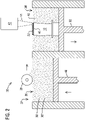
- FIG. 2 illustrates an additive manufacturing process such as selective laser sintering or selective laser melting, collectively referred to herein as selective laser heating, in accordance with an embodiment of the invention and used to form the tip portion 14 on the base portion 12.
- An additive manufacturing apparatus 30 includes a powder feed portion 32 and a fabrication portion 34.
- the powder feed portion 32 contains a volume of powder 36 which is selectively moved to the fabrication portion 34 by a powder feed and distribution device such as roller 38, which delivers a predetermined thickness of unprocessed powder 36 across the top surface of a fabrication powder bed 40 of the fabrication portion 34.
- a scanning system 42 then selectively scans an energy beam such as laser beam 44 in a programmed pattern across portions of the surface of the fabrication powder bed 40 to selectively heat (melt, partially melt or sinter) and solidify a region of the powder and thereby form a deposit layer 46 on the base portion 12.
- an energy beam such as laser beam 44
- a delivery piston 48 then moves upward to make additional powder 36 available to the roller 38
- a fabrication piston 50 moves downward to allow the fabrication powder bed 40 to receive another layer of powder 36, and the process is repeated with a pattern of indexing of the laser beam 44 effective to form a desired shape of the tip portion 14.
- powdered superalloy material is heated under an inert cover gas in order to protect the melted or partially melted powder 36 from contact with air.
- the embodiment of the present invention illustrated in FIG. 2 utilizes powdered superalloy material 36' plus powdered flux 36" as the powder 36, and thus the heating need not be (although it may optionally be) performed under an inert cover gas because melted flux provides the necessary shielding from air.
- the powder 36 may be a mixture of the powdered superalloy material 36' and powdered flux 36", or it may be composite particles of alloy and flux, as described above.
- the powder 36 may be of a fine mesh, for example 20 to 100 microns, and the mesh size range of particles of the powdered flux 36" may overlap or be the same as the mesh size range of particles of the powdered superalloy material 36'.
- the powdered flux 36" functions as a light trap to assist in the absorption of laser energy, and the resulting slag 52 slows the cooling rate and contains process energy.
- the powdered flux 36" may be formulated to contribute to the deposit chemistry in some embodiments. While not required, it may be advantageous to heat the powder 36 and/or the base portion 12 prior to a heating step. Post process hot isostatic pressing is also not required but may be used in some embodiments. Post weld heat treatment of the completed blade 10 may be performed with a low risk of reheat cracking even for difficult to weld superalloys.
- FIG. 3 shows a cross section of an exemplary embodiment of the tip portion 14 along line 3-3 of FIG. 1 .
- the tip portion includes a corrugated wall 60 having a suction side 62, a pressure side 64, and a corrugated rib 66 spanning there between.
- the suction side 62 and the pressure side 64 each span from a leading edge 70 to a trailing edge 72.
- a corrugated structure e.g. a wall or rib
- the integral connections 78 define openings 80 between the outer panel 74 and the inner panel 76, and the openings 80 may optionally define cooling channels 82.
- the corrugated wall 60 is characterized by a thickness 84 that may be approximately two (2) millimeters.
- the outer panel 74, the inner panel 76, and the integral connections 78 each are characterized according to the invention by a thickness as low as 0.5 millimeters, depending upon the limits of the additive manufacturing process.
- the integral connections 78 may define openings 80 having any cross sectional shape desired.
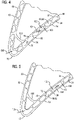
- FIGS. 4-7 show close ups of exemplary alternative embodiments of a leading edge region of the blade of FIG. 1 .
- FIG. 4 shows an exemplary embodiment where the openings 80 are characterized in cross section by a semi-circular shape 90 having a curved side 92 and a flat side 94.
- an orientation of the semi-circular shape 90 alternates from the leading edge 70 to the trailing edge 72.
- This configuration yields integral connections 78 that are angled with respect to the outer panel 74 and the inner panel 76. This provides a stiffness benefit while fillets 96 formed at respective interfaces reduce stress risers.
- An outer panel thickness 100, an inner panel thickness 102, and an integral connection thickness 104 are according to the invention as little as 0.5 millimeters and may remain constant or may vary locally as necessary.
- an outer panel leading edge thickness 106 may be approximately one (1) millimeter while the outer panel thickness 100 is 0.5 millimeters elsewhere. This type of local tailoring of the dimensions and shape of the corrugated wall 60 is made possible through the proposed use of the additive manufacturing process. Also visible is a non-corrugated rib 108 spanning the outer panel 74 and the inner panel 76. Corrugated ribs 66, non-corrugated ribs 108, or a combination of both may be used in a given tip portion 14 as desired. Corrugated ribs 66 may include the openings 80 in the shapes disclosed as well as any desired shape.
- FIGS. 5-7 show alternate cross sectional shapes of the openings 80 that may be formed by the integral connections 78.
- FIG. 5 shows rectangular shapes having rounded corners
- FIG. 6 shows trapezoidal shapes also having rounded corners.
- FIG. 7 shows elliptical openings.
- Any cross section desired may readily be formed when using the additive manufacturing process as proposed, and a single blade may include different wall corrugation designs in different regions of the blade, as well as walls that include both solid and corrugated portions along a given cross-section.
- a corrugated wall when viewed in cross-section as shown in FIGs. 3-7 may typically include a void/solid area ratio of 55-75%.
- the tip portion 14 of the blade 10 may be formed to have a different material composition than the base portion 12.
- an alloy developed by The International Nickel Company, Inc., described in United States patent 3,061,426 and known as IN-100 is known to have a desirably lower density/strength ratio and could be useful for gas turbine blade applications.
- that alloy is difficult to cast and is subject to hot tearing when cast in the shape of a large blade.
- hot tearing can be controlled when depositing IN-100 via an additive manufacturing method
- the present invention facilitates the use of that relatively lighter material for the tip portion 14 of the blade 10 while using a more easily cast but denser material for the base portion 12, such as CM-247 alloy. Because the centrifugal force effect is more pronounced for mass located at the tip of the blade, the present invention enables a blade designer to capture much of the benefit of the use of IN-100 material while mitigating its disadvantages.
- the tip portion 14 of the blade 10 may be formed to have a different grain structure than the base portion 12.
- a directionally solidified (DS) tip portion 14 may be formed on a conventionally cast (CC) base portion 12.
- CC conventionally cast
- directionally solidified grains of material can be produced.
- the substrate layer of the base portion 12 is conventionally cast and contains an equiaxed grain structure, it may be useful to first deposit one or more relatively thicker cladding layers (for example 2 mm laser cladding layer) to encourage the initiation of directionally solidified (vertically oriented) grains. Subsequent layers may then be much thinner (for example 0.5 mm selective laser melted layers) to form the desired geometry of the tip portion 14.
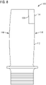
- FIG. 8 illustrates a gas turbine engine blade 110 having a base portion 112 formed by a traditional casting process and a tip portion 114 formed by an additive manufacturing process.
- the tip portion 114 extends only proximate a trailing edge 116 of the blade 110, while the leading edge 118 of the blade 110 is fully within the base portion 112.
- the trailing edge tip region is often the most highly thermally stressed region of a gas turbine blade.
- the present invention allows that region to be specially designed in response to such conditions, such as by being formed of a different material than the base portion 112 and/or by incorporating a unique cooling passageway geometry that may not be possible using conventional casting techniques.
- the interface 120 between the cast base portion 112 and the additively manufactured portion 114 may be defined by the blade designer to optimize the advantages of both the casting and additive manufacturing processes.
- the radial length of the tip portion 114 may extend in the range of 10-90% of the total radial length of the airfoil portion of the blade 110 (e.g. radial length of leading edge 118).
- more than one region of the blade may be formed by additive manufacturing processes.
- the proposed method simplifies and decreases the cost of the casting step while permitting better control of the tip portion.
- the result is a turbine blade that is easy to manufacture, has higher yield, and increases turbine engine efficiency. Therefore, it represents an improvement in the art.
Landscapes
- Engineering & Computer Science (AREA)
- Manufacturing & Machinery (AREA)
- Chemical & Material Sciences (AREA)
- Materials Engineering (AREA)
- Mechanical Engineering (AREA)
- Physics & Mathematics (AREA)
- Plasma & Fusion (AREA)
- Composite Materials (AREA)
- Architecture (AREA)
- General Engineering & Computer Science (AREA)
- Turbine Rotor Nozzle Sealing (AREA)
- Powder Metallurgy (AREA)
Claims (12)
- Procédé de fabrication d'une aube de moteur à turbine à gaz (10), le procédé comprenant :
la formation d'une partie de pointe (14) de l'aube sur une partie de base coulée (12) de l'aube par un procédé de fabrication additive, le procédé comprenant en outre :
la formation de la partie de pointe (14) pour qu'elle comprenne une paroi ondulée (60) par le procédé de fabrication additive, et comprenant en outre :
la formation de la paroi ondulée (60) pour qu'elle comprenne un panneau intérieur (76), un panneau extérieur (74) et la formation du panneau intérieur (76) et du panneau extérieur (74) de telle sorte que chacun comprenne une épaisseur en section transversale qui n'est pas supérieure à 0,5 millimètre dans au moins un emplacement respectif. - Procédé selon la revendication 1, la partie de base coulée (12) comprenant une structure de grain équiaxe coulée de manière conventionnelle, et comprenant en outre la formation de la partie de pointe (14) pour qu'elle comprenne une structure de grain solidifiée de manière directionnelle.
- Procédé selon la revendication 1, comprenant en outre :la formation de la paroi ondulée (60) pour qu'elle comprenne des ouvertures (80) lorsqu'elle est vue en coupe transversale, les ouvertures ayant une forme en coupe transversale choisie dans un groupe constitué par les formes rectangulaire, trapézoïdale et elliptique, oula formation de la paroi ondulée (60) pour qu'elle comprenne une pluralité d'ouvertures (80) ayant des formes semi-circulaires lorsqu'elle est vue en coupe transversale, et disposées dans une direction allant d'un bord d'attaque (70) de la paroi ondulée (60) à un bord de fuite (72) de la paroi ondulée (60) sur une longueur de la paroi, des formes semi-circulaires adjacentes ayant des orientations alternées, oula formation de la partie de pointe (14) pour qu'elle comprenne une épaisseur de paroi en coupe transversale qui est différente à deux emplacements le long d'une paroi de l'aube, ou la formation de la partie de pointe (14) pour qu'elle comprenne une nervure structurelle ondulée (66) par le procédé de fabrication additive, oula formation de la partie de pointe (14) de sorte qu'une longueur radiale de la partie de pointe est de 5 à 40 % d'une longueur radiale totale de l'aube.
- Procédé selon la revendication 1, la partie de pointe (14) s'étendant uniquement à proximité d'un bord de fuite (72) de l'aube, et un bord d'attaque (70) de l'aube étant entièrement à l'intérieur de la partie de base (12).
- Aube (10) de moteur à turbine à gaz comprenant :une partie de base (12) comprenant une paroi coulée ; etune partie de pointe (14) fixée à la partie de base (12) et comprenant une paroi ondulée (60) formée par un procédé de fabrication additive, la paroi ondulée (60) comprenant un panneau intérieur (76), un panneau extérieur (74), et des connexions intégrées (78) entre eux, et le panneau intérieur (76) et le panneau extérieur (74) comprenant chacun une épaisseur qui n'est pas supérieure à 0,5 millimètre dans au moins un emplacement respectif.
- Aube selon la revendication 5, la partie de base (12) comprenant une structure de grain équiaxe, et la partie de pointe (14) comprenant une structure de grain solidifiée de manière directionnelle.
- Aube selon la revendication 5, la paroi ondulée (60) comprenant des ouvertures (80), et, lorsqu'elle elle est vue en coupe transversale, les ouvertures (80) ayant une forme choisie dans un groupe constitué par les formes rectangulaire, trapézoïdale et elliptique.
- Aube selon la revendication 5, la paroi ondulée (60) comprenant des ouvertures (80), et, lorsqu'elle est vue en coupe transversale, les ouvertures (80) comprenant des formes semi-circulaires dont l'orientation alterne entre un bord d'attaque (70) de la paroi ondulée (60) et un bord de fuite (72) de la paroi ondulée (60).
- Aube selon la revendication 5, une épaisseur de la paroi ondulée (60) étant différente entre deux emplacements le long de la paroi.
- Aube selon la revendication 5, la partie de pointe (14) comprenant en outre une nervure ondulée (66) formée par le procédé de fabrication additive.
- Aube selon la revendication 5, une longueur de la partie de pointe (14) étant de 5 à 40 % d'une longueur radiale totale de l'aube.
- Aube selon la revendication 5, la partie de pointe (14) s'étendant seulement à proximité d'un bord de fuite (72) de l'aube, et un bord d'attaque (70) de l'aube étant entièrement à l'intérieur de la partie de base (12).
Applications Claiming Priority (2)
| Application Number | Priority Date | Filing Date | Title |
|---|---|---|---|
| US15/139,379 US10260352B2 (en) | 2013-08-01 | 2016-04-27 | Gas turbine blade with corrugated tip wall |
| PCT/US2017/026484 WO2017189208A1 (fr) | 2016-04-27 | 2017-04-07 | Aube de turbine à gaz à paroi de pointe ondulée |
Publications (2)
| Publication Number | Publication Date |
|---|---|
| EP3433040A1 EP3433040A1 (fr) | 2019-01-30 |
| EP3433040B1 true EP3433040B1 (fr) | 2023-01-25 |
Family
ID=59366481
Family Applications (1)
| Application Number | Title | Priority Date | Filing Date |
|---|---|---|---|
| EP17740814.3A Active EP3433040B1 (fr) | 2016-04-27 | 2017-04-07 | Aube de turbine à gaz à paroi de pointe ondulée et son procédé de fabrication |
Country Status (3)
| Country | Link |
|---|---|
| EP (1) | EP3433040B1 (fr) |
| CN (1) | CN108698128B (fr) |
| WO (1) | WO2017189208A1 (fr) |
Families Citing this family (3)
| Publication number | Priority date | Publication date | Assignee | Title |
|---|---|---|---|---|
| DE102019201085A1 (de) | 2019-01-29 | 2020-07-30 | Siemens Aktiengesellschaft | Herstellungsverfahren für ein Bauteil mit integrierten Kanälen |
| EP3804885A1 (fr) * | 2019-10-11 | 2021-04-14 | Heraeus Additive Manufacturing GmbH | Procédé de fabrication d'un composant métallique comportant une section à rapport d'aspect élevé |
| CN111036923A (zh) * | 2019-12-06 | 2020-04-21 | 西安铂力特增材技术股份有限公司 | 结合铸造与选区激光熔化成形制造大型金属零件的方法 |
Family Cites Families (14)
| Publication number | Priority date | Publication date | Assignee | Title |
|---|---|---|---|---|
| NL260545A (fr) | 1960-02-01 | |||
| US5626462A (en) | 1995-01-03 | 1997-05-06 | General Electric Company | Double-wall airfoil |
| JP5189406B2 (ja) * | 2008-05-14 | 2013-04-24 | 三菱重工業株式会社 | ガスタービン翼およびこれを備えたガスタービン |
| US20100104446A1 (en) * | 2008-10-28 | 2010-04-29 | General Electric Company | Fabricated hybrid turbine blade |
| US8079821B2 (en) * | 2009-05-05 | 2011-12-20 | Siemens Energy, Inc. | Turbine airfoil with dual wall formed from inner and outer layers separated by a compliant structure |
| US8979498B2 (en) | 2010-03-03 | 2015-03-17 | Siemens Energy, Inc. | Turbine airfoil having outboard and inboard sections |
| US9995148B2 (en) * | 2012-10-04 | 2018-06-12 | General Electric Company | Method and apparatus for cooling gas turbine and rotor blades |
| US8720526B1 (en) | 2012-11-13 | 2014-05-13 | Siemens Energy, Inc. | Process for forming a long gas turbine engine blade having a main wall with a thin portion near a tip |
| EP2772329A1 (fr) * | 2013-02-28 | 2014-09-03 | Alstom Technology Ltd | Procédé de fabrication d'un composant hybride |
| US20150033559A1 (en) | 2013-08-01 | 2015-02-05 | Gerald J. Bruck | Repair of a substrate with component supported filler |
| US20150034266A1 (en) | 2013-08-01 | 2015-02-05 | Siemens Energy, Inc. | Building and repair of hollow components |
| US20150204237A1 (en) * | 2014-01-17 | 2015-07-23 | General Electric Company | Turbine blade and method for enhancing life of the turbine blade |
| US9777574B2 (en) * | 2014-08-18 | 2017-10-03 | Siemens Energy, Inc. | Method for repairing a gas turbine engine blade tip |
| CN104907492B (zh) * | 2015-05-07 | 2017-03-08 | 西安交通大学 | 一种面向双层壁空心涡轮叶片的制造方法 |
-
2017
- 2017-04-07 EP EP17740814.3A patent/EP3433040B1/fr active Active
- 2017-04-07 CN CN201780013944.4A patent/CN108698128B/zh active Active
- 2017-04-07 WO PCT/US2017/026484 patent/WO2017189208A1/fr not_active Ceased
Also Published As
| Publication number | Publication date |
|---|---|
| CN108698128A (zh) | 2018-10-23 |
| EP3433040A1 (fr) | 2019-01-30 |
| CN108698128B (zh) | 2021-01-29 |
| WO2017189208A1 (fr) | 2017-11-02 |
Similar Documents
| Publication | Publication Date | Title |
|---|---|---|
| US10260352B2 (en) | Gas turbine blade with corrugated tip wall | |
| US9393620B2 (en) | Uber-cooled turbine section component made by additive manufacturing | |
| JP5197929B2 (ja) | ニオブシリサイド基タービン構成部品および関連するレーザ付着方法 | |
| CN104662274B (zh) | 通过增材制造技术制备的超级冷却的涡轮区段组件 | |
| EP2620594B1 (fr) | Méthode de fabrication de composant de turbine à matériaux multiples | |
| EP2708296B1 (fr) | Procédés de fabrication d'ensembles de surfaces portantes de stator de turbine par méthodes de fabrication additive | |
| EP2540419B1 (fr) | Procédés de fabrication de composants de moteur avec dispositifs de pont structurel | |
| EP2366476B1 (fr) | Procédé de fabrication de surfaces portantes de turbine et structures à pointe associées | |
| US20150196971A1 (en) | Method for the Regenerative Production of a Turbine Wheel with a Shroud | |
| US20100200189A1 (en) | Method of fabricating turbine airfoils and tip structures therefor | |
| JP2017504714A (ja) | 単結晶合金部品の積層製造 | |
| EP3428395B1 (fr) | Aube de soufflante et procédé de fabrication | |
| US7690112B2 (en) | Process and apparatus for producing a turbine component, turbine component and use of the apparatus | |
| US20180161872A1 (en) | Method for producing a turbine blade by means of electron beam melting | |
| JP6356801B2 (ja) | 負のcte特徴を有するタービン部品 | |
| EP3433040B1 (fr) | Aube de turbine à gaz à paroi de pointe ondulée et son procédé de fabrication | |
| JP2009502503A (ja) | 方向性ミクロ組織の母材を有する部品の修復方法とその部品 | |
| JP2017115864A (ja) | 物品及び物品を形成する方法 | |
| JP2010106833A (ja) | ハイブリッドタービン動翼 | |
| EP3315228B1 (fr) | Composant provenant de la fabrication additive pour une turbine a gaz | |
| CN115194284A (zh) | 无炉钎焊方法 |
Legal Events
| Date | Code | Title | Description |
|---|---|---|---|
| STAA | Information on the status of an ep patent application or granted ep patent |
Free format text: STATUS: UNKNOWN |
|
| STAA | Information on the status of an ep patent application or granted ep patent |
Free format text: STATUS: THE INTERNATIONAL PUBLICATION HAS BEEN MADE |
|
| PUAI | Public reference made under article 153(3) epc to a published international application that has entered the european phase |
Free format text: ORIGINAL CODE: 0009012 |
|
| STAA | Information on the status of an ep patent application or granted ep patent |
Free format text: STATUS: REQUEST FOR EXAMINATION WAS MADE |
|
| 17P | Request for examination filed |
Effective date: 20181023 |
|
| AK | Designated contracting states |
Kind code of ref document: A1 Designated state(s): AL AT BE BG CH CY CZ DE DK EE ES FI FR GB GR HR HU IE IS IT LI LT LU LV MC MK MT NL NO PL PT RO RS SE SI SK SM TR |
|
| AX | Request for extension of the european patent |
Extension state: BA ME |
|
| DAV | Request for validation of the european patent (deleted) | ||
| DAX | Request for extension of the european patent (deleted) | ||
| STAA | Information on the status of an ep patent application or granted ep patent |
Free format text: STATUS: EXAMINATION IS IN PROGRESS |
|
| 17Q | First examination report despatched |
Effective date: 20220223 |
|
| REG | Reference to a national code |
Ref country code: DE Ref legal event code: R079 Ref document number: 602017065753 Country of ref document: DE Free format text: PREVIOUS MAIN CLASS: B22F0003105000 Ipc: B22F0005040000 |
|
| GRAP | Despatch of communication of intention to grant a patent |
Free format text: ORIGINAL CODE: EPIDOSNIGR1 |
|
| STAA | Information on the status of an ep patent application or granted ep patent |
Free format text: STATUS: GRANT OF PATENT IS INTENDED |
|
| RIC1 | Information provided on ipc code assigned before grant |
Ipc: F01D 5/20 20060101ALN20220812BHEP Ipc: F01D 5/14 20060101ALI20220812BHEP Ipc: B33Y 80/00 20150101ALI20220812BHEP Ipc: B33Y 10/00 20150101ALI20220812BHEP Ipc: B22F 10/28 20210101ALI20220812BHEP Ipc: B22F 7/08 20060101ALI20220812BHEP Ipc: B22F 5/04 20060101AFI20220812BHEP |
|
| INTG | Intention to grant announced |
Effective date: 20220915 |
|
| GRAS | Grant fee paid |
Free format text: ORIGINAL CODE: EPIDOSNIGR3 |
|
| GRAA | (expected) grant |
Free format text: ORIGINAL CODE: 0009210 |
|
| STAA | Information on the status of an ep patent application or granted ep patent |
Free format text: STATUS: THE PATENT HAS BEEN GRANTED |
|
| AK | Designated contracting states |
Kind code of ref document: B1 Designated state(s): AL AT BE BG CH CY CZ DE DK EE ES FI FR GB GR HR HU IE IS IT LI LT LU LV MC MK MT NL NO PL PT RO RS SE SI SK SM TR |
|
| REG | Reference to a national code |
Ref country code: GB Ref legal event code: FG4D |
|
| REG | Reference to a national code |
Ref country code: CH Ref legal event code: EP |
|
| REG | Reference to a national code |
Ref country code: DE Ref legal event code: R096 Ref document number: 602017065753 Country of ref document: DE |
|
| REG | Reference to a national code |
Ref country code: AT Ref legal event code: REF Ref document number: 1545591 Country of ref document: AT Kind code of ref document: T Effective date: 20230215 Ref country code: IE Ref legal event code: FG4D |
|
| REG | Reference to a national code |
Ref country code: LT Ref legal event code: MG9D |
|
| REG | Reference to a national code |
Ref country code: AT Ref legal event code: MK05 Ref document number: 1545591 Country of ref document: AT Kind code of ref document: T Effective date: 20230125 |
|
| PG25 | Lapsed in a contracting state [announced via postgrant information from national office to epo] |
Ref country code: NL Free format text: LAPSE BECAUSE OF FAILURE TO SUBMIT A TRANSLATION OF THE DESCRIPTION OR TO PAY THE FEE WITHIN THE PRESCRIBED TIME-LIMIT Effective date: 20230125 |
|
| PG25 | Lapsed in a contracting state [announced via postgrant information from national office to epo] |
Ref country code: RS Free format text: LAPSE BECAUSE OF FAILURE TO SUBMIT A TRANSLATION OF THE DESCRIPTION OR TO PAY THE FEE WITHIN THE PRESCRIBED TIME-LIMIT Effective date: 20230125 Ref country code: PT Free format text: LAPSE BECAUSE OF FAILURE TO SUBMIT A TRANSLATION OF THE DESCRIPTION OR TO PAY THE FEE WITHIN THE PRESCRIBED TIME-LIMIT Effective date: 20230525 Ref country code: NO Free format text: LAPSE BECAUSE OF FAILURE TO SUBMIT A TRANSLATION OF THE DESCRIPTION OR TO PAY THE FEE WITHIN THE PRESCRIBED TIME-LIMIT Effective date: 20230425 Ref country code: LV Free format text: LAPSE BECAUSE OF FAILURE TO SUBMIT A TRANSLATION OF THE DESCRIPTION OR TO PAY THE FEE WITHIN THE PRESCRIBED TIME-LIMIT Effective date: 20230125 Ref country code: LT Free format text: LAPSE BECAUSE OF FAILURE TO SUBMIT A TRANSLATION OF THE DESCRIPTION OR TO PAY THE FEE WITHIN THE PRESCRIBED TIME-LIMIT Effective date: 20230125 Ref country code: HR Free format text: LAPSE BECAUSE OF FAILURE TO SUBMIT A TRANSLATION OF THE DESCRIPTION OR TO PAY THE FEE WITHIN THE PRESCRIBED TIME-LIMIT Effective date: 20230125 Ref country code: ES Free format text: LAPSE BECAUSE OF FAILURE TO SUBMIT A TRANSLATION OF THE DESCRIPTION OR TO PAY THE FEE WITHIN THE PRESCRIBED TIME-LIMIT Effective date: 20230125 Ref country code: AT Free format text: LAPSE BECAUSE OF FAILURE TO SUBMIT A TRANSLATION OF THE DESCRIPTION OR TO PAY THE FEE WITHIN THE PRESCRIBED TIME-LIMIT Effective date: 20230125 |
|
| PG25 | Lapsed in a contracting state [announced via postgrant information from national office to epo] |
Ref country code: SE Free format text: LAPSE BECAUSE OF FAILURE TO SUBMIT A TRANSLATION OF THE DESCRIPTION OR TO PAY THE FEE WITHIN THE PRESCRIBED TIME-LIMIT Effective date: 20230125 Ref country code: PL Free format text: LAPSE BECAUSE OF FAILURE TO SUBMIT A TRANSLATION OF THE DESCRIPTION OR TO PAY THE FEE WITHIN THE PRESCRIBED TIME-LIMIT Effective date: 20230125 Ref country code: IS Free format text: LAPSE BECAUSE OF FAILURE TO SUBMIT A TRANSLATION OF THE DESCRIPTION OR TO PAY THE FEE WITHIN THE PRESCRIBED TIME-LIMIT Effective date: 20230525 Ref country code: GR Free format text: LAPSE BECAUSE OF FAILURE TO SUBMIT A TRANSLATION OF THE DESCRIPTION OR TO PAY THE FEE WITHIN THE PRESCRIBED TIME-LIMIT Effective date: 20230426 Ref country code: FI Free format text: LAPSE BECAUSE OF FAILURE TO SUBMIT A TRANSLATION OF THE DESCRIPTION OR TO PAY THE FEE WITHIN THE PRESCRIBED TIME-LIMIT Effective date: 20230125 |
|
| REG | Reference to a national code |
Ref country code: DE Ref legal event code: R097 Ref document number: 602017065753 Country of ref document: DE |
|
| PG25 | Lapsed in a contracting state [announced via postgrant information from national office to epo] |
Ref country code: SM Free format text: LAPSE BECAUSE OF FAILURE TO SUBMIT A TRANSLATION OF THE DESCRIPTION OR TO PAY THE FEE WITHIN THE PRESCRIBED TIME-LIMIT Effective date: 20230125 Ref country code: RO Free format text: LAPSE BECAUSE OF FAILURE TO SUBMIT A TRANSLATION OF THE DESCRIPTION OR TO PAY THE FEE WITHIN THE PRESCRIBED TIME-LIMIT Effective date: 20230125 Ref country code: EE Free format text: LAPSE BECAUSE OF FAILURE TO SUBMIT A TRANSLATION OF THE DESCRIPTION OR TO PAY THE FEE WITHIN THE PRESCRIBED TIME-LIMIT Effective date: 20230125 Ref country code: DK Free format text: LAPSE BECAUSE OF FAILURE TO SUBMIT A TRANSLATION OF THE DESCRIPTION OR TO PAY THE FEE WITHIN THE PRESCRIBED TIME-LIMIT Effective date: 20230125 Ref country code: CZ Free format text: LAPSE BECAUSE OF FAILURE TO SUBMIT A TRANSLATION OF THE DESCRIPTION OR TO PAY THE FEE WITHIN THE PRESCRIBED TIME-LIMIT Effective date: 20230125 |
|
| PG25 | Lapsed in a contracting state [announced via postgrant information from national office to epo] |
Ref country code: SK Free format text: LAPSE BECAUSE OF FAILURE TO SUBMIT A TRANSLATION OF THE DESCRIPTION OR TO PAY THE FEE WITHIN THE PRESCRIBED TIME-LIMIT Effective date: 20230125 |
|
| REG | Reference to a national code |
Ref country code: CH Ref legal event code: PL |
|
| PLBE | No opposition filed within time limit |
Free format text: ORIGINAL CODE: 0009261 |
|
| STAA | Information on the status of an ep patent application or granted ep patent |
Free format text: STATUS: NO OPPOSITION FILED WITHIN TIME LIMIT |
|
| PG25 | Lapsed in a contracting state [announced via postgrant information from national office to epo] |
Ref country code: LU Free format text: LAPSE BECAUSE OF NON-PAYMENT OF DUE FEES Effective date: 20230407 |
|
| 26N | No opposition filed |
Effective date: 20231026 |
|
| REG | Reference to a national code |
Ref country code: BE Ref legal event code: MM Effective date: 20230430 |
|
| PG25 | Lapsed in a contracting state [announced via postgrant information from national office to epo] |
Ref country code: MC Free format text: LAPSE BECAUSE OF FAILURE TO SUBMIT A TRANSLATION OF THE DESCRIPTION OR TO PAY THE FEE WITHIN THE PRESCRIBED TIME-LIMIT Effective date: 20230125 |
|
| PG25 | Lapsed in a contracting state [announced via postgrant information from national office to epo] |
Ref country code: SI Free format text: LAPSE BECAUSE OF FAILURE TO SUBMIT A TRANSLATION OF THE DESCRIPTION OR TO PAY THE FEE WITHIN THE PRESCRIBED TIME-LIMIT Effective date: 20230125 Ref country code: MC Free format text: LAPSE BECAUSE OF FAILURE TO SUBMIT A TRANSLATION OF THE DESCRIPTION OR TO PAY THE FEE WITHIN THE PRESCRIBED TIME-LIMIT Effective date: 20230125 Ref country code: LI Free format text: LAPSE BECAUSE OF NON-PAYMENT OF DUE FEES Effective date: 20230430 Ref country code: FR Free format text: LAPSE BECAUSE OF NON-PAYMENT OF DUE FEES Effective date: 20230430 Ref country code: CH Free format text: LAPSE BECAUSE OF NON-PAYMENT OF DUE FEES Effective date: 20230430 |
|
| REG | Reference to a national code |
Ref country code: IE Ref legal event code: MM4A |
|
| PG25 | Lapsed in a contracting state [announced via postgrant information from national office to epo] |
Ref country code: BE Free format text: LAPSE BECAUSE OF NON-PAYMENT OF DUE FEES Effective date: 20230430 |
|
| PG25 | Lapsed in a contracting state [announced via postgrant information from national office to epo] |
Ref country code: IE Free format text: LAPSE BECAUSE OF NON-PAYMENT OF DUE FEES Effective date: 20230407 |
|
| PG25 | Lapsed in a contracting state [announced via postgrant information from national office to epo] |
Ref country code: IE Free format text: LAPSE BECAUSE OF NON-PAYMENT OF DUE FEES Effective date: 20230407 |
|
| PG25 | Lapsed in a contracting state [announced via postgrant information from national office to epo] |
Ref country code: BG Free format text: LAPSE BECAUSE OF FAILURE TO SUBMIT A TRANSLATION OF THE DESCRIPTION OR TO PAY THE FEE WITHIN THE PRESCRIBED TIME-LIMIT Effective date: 20230125 |
|
| PG25 | Lapsed in a contracting state [announced via postgrant information from national office to epo] |
Ref country code: BG Free format text: LAPSE BECAUSE OF FAILURE TO SUBMIT A TRANSLATION OF THE DESCRIPTION OR TO PAY THE FEE WITHIN THE PRESCRIBED TIME-LIMIT Effective date: 20230125 |
|
| PGFP | Annual fee paid to national office [announced via postgrant information from national office to epo] |
Ref country code: DE Payment date: 20250428 Year of fee payment: 9 |
|
| PGFP | Annual fee paid to national office [announced via postgrant information from national office to epo] |
Ref country code: IT Payment date: 20250422 Year of fee payment: 9 |
|
| PG25 | Lapsed in a contracting state [announced via postgrant information from national office to epo] |
Ref country code: CY Free format text: LAPSE BECAUSE OF FAILURE TO SUBMIT A TRANSLATION OF THE DESCRIPTION OR TO PAY THE FEE WITHIN THE PRESCRIBED TIME-LIMIT; INVALID AB INITIO Effective date: 20170407 |
|
| PG25 | Lapsed in a contracting state [announced via postgrant information from national office to epo] |
Ref country code: HU Free format text: LAPSE BECAUSE OF FAILURE TO SUBMIT A TRANSLATION OF THE DESCRIPTION OR TO PAY THE FEE WITHIN THE PRESCRIBED TIME-LIMIT; INVALID AB INITIO Effective date: 20170407 |
|
| PG25 | Lapsed in a contracting state [announced via postgrant information from national office to epo] |
Ref country code: TR Free format text: LAPSE BECAUSE OF FAILURE TO SUBMIT A TRANSLATION OF THE DESCRIPTION OR TO PAY THE FEE WITHIN THE PRESCRIBED TIME-LIMIT Effective date: 20230125 |
|
| PGFP | Annual fee paid to national office [announced via postgrant information from national office to epo] |
Ref country code: GB Payment date: 20260323 Year of fee payment: 10 |