EP3434123B1 - Dispositif de protection - Google Patents
Dispositif de protection Download PDFInfo
- Publication number
- EP3434123B1 EP3434123B1 EP18185551.1A EP18185551A EP3434123B1 EP 3434123 B1 EP3434123 B1 EP 3434123B1 EP 18185551 A EP18185551 A EP 18185551A EP 3434123 B1 EP3434123 B1 EP 3434123B1
- Authority
- EP
- European Patent Office
- Prior art keywords
- inflatable element
- wall
- inflatable
- mesh
- partially
- Prior art date
- Legal status (The legal status is an assumption and is not a legal conclusion. Google has not performed a legal analysis and makes no representation as to the accuracy of the status listed.)
- Active
Links
Images

Classifications
-
- A—HUMAN NECESSITIES
- A41—WEARING APPAREL
- A41D—OUTERWEAR; PROTECTIVE GARMENTS; ACCESSORIES
- A41D13/00—Professional, industrial or sporting protective garments, e.g. surgeons' gowns or garments protecting against blows or punches
- A41D13/015—Professional, industrial or sporting protective garments, e.g. surgeons' gowns or garments protecting against blows or punches with shock-absorbing means
- A41D13/018—Professional, industrial or sporting protective garments, e.g. surgeons' gowns or garments protecting against blows or punches with shock-absorbing means inflatable automatically
-
- A—HUMAN NECESSITIES
- A41—WEARING APPAREL
- A41D—OUTERWEAR; PROTECTIVE GARMENTS; ACCESSORIES
- A41D13/00—Professional, industrial or sporting protective garments, e.g. surgeons' gowns or garments protecting against blows or punches
- A41D13/05—Professional, industrial or sporting protective garments, e.g. surgeons' gowns or garments protecting against blows or punches protecting only a particular body part
- A41D13/0512—Neck or shoulders area
-
- B—PERFORMING OPERATIONS; TRANSPORTING
- B32—LAYERED PRODUCTS
- B32B—LAYERED PRODUCTS, i.e. PRODUCTS BUILT-UP OF STRATA OF FLAT OR NON-FLAT, e.g. CELLULAR OR HONEYCOMB, FORM
- B32B3/00—Layered products comprising a layer with external or internal discontinuities or unevennesses, or a layer of non-planar shape; Layered products comprising a layer having particular features of form
- B32B3/26—Layered products comprising a layer with external or internal discontinuities or unevennesses, or a layer of non-planar shape; Layered products comprising a layer having particular features of form characterised by a particular shape of the outline of the cross-section of a continuous layer; characterised by a layer with cavities or internal voids ; characterised by an apertured layer
- B32B3/266—Layered products comprising a layer with external or internal discontinuities or unevennesses, or a layer of non-planar shape; Layered products comprising a layer having particular features of form characterised by a particular shape of the outline of the cross-section of a continuous layer; characterised by a layer with cavities or internal voids ; characterised by an apertured layer characterised by an apertured layer, the apertures going through the whole thickness of the layer, e.g. expanded metal, perforated layer, slit layer regular cells B32B3/12
-
- B—PERFORMING OPERATIONS; TRANSPORTING
- B32—LAYERED PRODUCTS
- B32B—LAYERED PRODUCTS, i.e. PRODUCTS BUILT-UP OF STRATA OF FLAT OR NON-FLAT, e.g. CELLULAR OR HONEYCOMB, FORM
- B32B5/00—Layered products characterised by the non- homogeneity or physical structure, i.e. comprising a fibrous, filamentary, particulate or foam layer; Layered products characterised by having a layer differing constitutionally or physically in different parts
- B32B5/02—Layered products characterised by the non- homogeneity or physical structure, i.e. comprising a fibrous, filamentary, particulate or foam layer; Layered products characterised by having a layer differing constitutionally or physically in different parts characterised by structural features of a fibrous or filamentary layer
- B32B5/026—Knitted fabric
-
- B—PERFORMING OPERATIONS; TRANSPORTING
- B32—LAYERED PRODUCTS
- B32B—LAYERED PRODUCTS, i.e. PRODUCTS BUILT-UP OF STRATA OF FLAT OR NON-FLAT, e.g. CELLULAR OR HONEYCOMB, FORM
- B32B5/00—Layered products characterised by the non- homogeneity or physical structure, i.e. comprising a fibrous, filamentary, particulate or foam layer; Layered products characterised by having a layer differing constitutionally or physically in different parts
- B32B5/22—Layered products characterised by the non- homogeneity or physical structure, i.e. comprising a fibrous, filamentary, particulate or foam layer; Layered products characterised by having a layer differing constitutionally or physically in different parts characterised by the presence of two or more layers which are next to each other and are fibrous, filamentary, formed of particles or foamed
- B32B5/24—Layered products characterised by the non- homogeneity or physical structure, i.e. comprising a fibrous, filamentary, particulate or foam layer; Layered products characterised by having a layer differing constitutionally or physically in different parts characterised by the presence of two or more layers which are next to each other and are fibrous, filamentary, formed of particles or foamed one layer being a fibrous or filamentary layer
- B32B5/26—Layered products characterised by the non- homogeneity or physical structure, i.e. comprising a fibrous, filamentary, particulate or foam layer; Layered products characterised by having a layer differing constitutionally or physically in different parts characterised by the presence of two or more layers which are next to each other and are fibrous, filamentary, formed of particles or foamed one layer being a fibrous or filamentary layer another layer next to it also being fibrous or filamentary
-
- B—PERFORMING OPERATIONS; TRANSPORTING
- B32—LAYERED PRODUCTS
- B32B—LAYERED PRODUCTS, i.e. PRODUCTS BUILT-UP OF STRATA OF FLAT OR NON-FLAT, e.g. CELLULAR OR HONEYCOMB, FORM
- B32B7/00—Layered products characterised by the relation between layers; Layered products characterised by the relative orientation of features between layers, or by the relative values of a measurable parameter between layers, i.e. products comprising layers having different physical, chemical or physicochemical properties; Layered products characterised by the interconnection of layers
- B32B7/04—Interconnection of layers
- B32B7/05—Interconnection of layers the layers not being connected over the whole surface, e.g. discontinuous connection or patterned connection
-
- B—PERFORMING OPERATIONS; TRANSPORTING
- B32—LAYERED PRODUCTS
- B32B—LAYERED PRODUCTS, i.e. PRODUCTS BUILT-UP OF STRATA OF FLAT OR NON-FLAT, e.g. CELLULAR OR HONEYCOMB, FORM
- B32B7/00—Layered products characterised by the relation between layers; Layered products characterised by the relative orientation of features between layers, or by the relative values of a measurable parameter between layers, i.e. products comprising layers having different physical, chemical or physicochemical properties; Layered products characterised by the interconnection of layers
- B32B7/04—Interconnection of layers
- B32B7/12—Interconnection of layers using interposed adhesives or interposed materials with bonding properties
-
- B—PERFORMING OPERATIONS; TRANSPORTING
- B60—VEHICLES IN GENERAL
- B60R—VEHICLES, VEHICLE FITTINGS, OR VEHICLE PARTS, NOT OTHERWISE PROVIDED FOR
- B60R21/00—Arrangements or fittings on vehicles for protecting or preventing injuries to occupants or pedestrians in case of accidents or other traffic risks
- B60R21/02—Occupant safety arrangements or fittings, e.g. crash pads
- B60R21/16—Inflatable occupant restraints or confinements designed to inflate upon impact or impending impact, e.g. air bags
- B60R21/23—Inflatable members
- B60R21/231—Inflatable members characterised by their shape, construction or spatial configuration
- B60R21/233—Inflatable members characterised by their shape, construction or spatial configuration comprising a plurality of individual compartments; comprising two or more bag-like members, one within the other
-
- B—PERFORMING OPERATIONS; TRANSPORTING
- B60—VEHICLES IN GENERAL
- B60R—VEHICLES, VEHICLE FITTINGS, OR VEHICLE PARTS, NOT OTHERWISE PROVIDED FOR
- B60R21/00—Arrangements or fittings on vehicles for protecting or preventing injuries to occupants or pedestrians in case of accidents or other traffic risks
- B60R21/02—Occupant safety arrangements or fittings, e.g. crash pads
- B60R21/16—Inflatable occupant restraints or confinements designed to inflate upon impact or impending impact, e.g. air bags
- B60R21/23—Inflatable members
- B60R21/231—Inflatable members characterised by their shape, construction or spatial configuration
- B60R21/2334—Expansion control features
- B60R21/2338—Tethers
-
- B—PERFORMING OPERATIONS; TRANSPORTING
- B60—VEHICLES IN GENERAL
- B60R—VEHICLES, VEHICLE FITTINGS, OR VEHICLE PARTS, NOT OTHERWISE PROVIDED FOR
- B60R21/00—Arrangements or fittings on vehicles for protecting or preventing injuries to occupants or pedestrians in case of accidents or other traffic risks
- B60R21/02—Occupant safety arrangements or fittings, e.g. crash pads
- B60R21/16—Inflatable occupant restraints or confinements designed to inflate upon impact or impending impact, e.g. air bags
- B60R21/23—Inflatable members
- B60R21/235—Inflatable members characterised by their material
-
- A—HUMAN NECESSITIES
- A41—WEARING APPAREL
- A41D—OUTERWEAR; PROTECTIVE GARMENTS; ACCESSORIES
- A41D13/00—Professional, industrial or sporting protective garments, e.g. surgeons' gowns or garments protecting against blows or punches
- A41D13/05—Professional, industrial or sporting protective garments, e.g. surgeons' gowns or garments protecting against blows or punches protecting only a particular body part
- A41D13/0518—Chest
-
- A—HUMAN NECESSITIES
- A41—WEARING APPAREL
- A41D—OUTERWEAR; PROTECTIVE GARMENTS; ACCESSORIES
- A41D13/00—Professional, industrial or sporting protective garments, e.g. surgeons' gowns or garments protecting against blows or punches
- A41D13/05—Professional, industrial or sporting protective garments, e.g. surgeons' gowns or garments protecting against blows or punches protecting only a particular body part
- A41D13/0531—Spine
-
- A—HUMAN NECESSITIES
- A41—WEARING APPAREL
- A41D—OUTERWEAR; PROTECTIVE GARMENTS; ACCESSORIES
- A41D2500/00—Materials for garments
- A41D2500/10—Knitted
-
- A—HUMAN NECESSITIES
- A41—WEARING APPAREL
- A41D—OUTERWEAR; PROTECTIVE GARMENTS; ACCESSORIES
- A41D2600/00—Uses of garments specially adapted for specific purposes
- A41D2600/10—Uses of garments specially adapted for specific purposes for sport activities
- A41D2600/102—Motorcycling
-
- A—HUMAN NECESSITIES
- A41—WEARING APPAREL
- A41D—OUTERWEAR; PROTECTIVE GARMENTS; ACCESSORIES
- A41D31/00—Materials specially adapted for outerwear
- A41D31/04—Materials specially adapted for outerwear characterised by special function or use
- A41D31/28—Shock absorbing
- A41D31/285—Shock absorbing using layered materials
-
- B—PERFORMING OPERATIONS; TRANSPORTING
- B32—LAYERED PRODUCTS
- B32B—LAYERED PRODUCTS, i.e. PRODUCTS BUILT-UP OF STRATA OF FLAT OR NON-FLAT, e.g. CELLULAR OR HONEYCOMB, FORM
- B32B2307/00—Properties of the layers or laminate
- B32B2307/50—Properties of the layers or laminate having particular mechanical properties
- B32B2307/58—Cuttability
-
- B—PERFORMING OPERATIONS; TRANSPORTING
- B32—LAYERED PRODUCTS
- B32B—LAYERED PRODUCTS, i.e. PRODUCTS BUILT-UP OF STRATA OF FLAT OR NON-FLAT, e.g. CELLULAR OR HONEYCOMB, FORM
- B32B2437/00—Clothing
-
- B—PERFORMING OPERATIONS; TRANSPORTING
- B32—LAYERED PRODUCTS
- B32B—LAYERED PRODUCTS, i.e. PRODUCTS BUILT-UP OF STRATA OF FLAT OR NON-FLAT, e.g. CELLULAR OR HONEYCOMB, FORM
- B32B2437/00—Clothing
- B32B2437/04—Caps, helmets
-
- B—PERFORMING OPERATIONS; TRANSPORTING
- B32—LAYERED PRODUCTS
- B32B—LAYERED PRODUCTS, i.e. PRODUCTS BUILT-UP OF STRATA OF FLAT OR NON-FLAT, e.g. CELLULAR OR HONEYCOMB, FORM
- B32B2571/00—Protective equipment
-
- B—PERFORMING OPERATIONS; TRANSPORTING
- B60—VEHICLES IN GENERAL
- B60R—VEHICLES, VEHICLE FITTINGS, OR VEHICLE PARTS, NOT OTHERWISE PROVIDED FOR
- B60R21/00—Arrangements or fittings on vehicles for protecting or preventing injuries to occupants or pedestrians in case of accidents or other traffic risks
- B60R21/02—Occupant safety arrangements or fittings, e.g. crash pads
- B60R21/16—Inflatable occupant restraints or confinements designed to inflate upon impact or impending impact, e.g. air bags
- B60R21/23—Inflatable members
- B60R21/231—Inflatable members characterised by their shape, construction or spatial configuration
- B60R21/233—Inflatable members characterised by their shape, construction or spatial configuration comprising a plurality of individual compartments; comprising two or more bag-like members, one within the other
- B60R2021/23308—Inflatable members characterised by their shape, construction or spatial configuration comprising a plurality of individual compartments; comprising two or more bag-like members, one within the other the individual compartments defining the external shape of the bag
-
- B—PERFORMING OPERATIONS; TRANSPORTING
- B60—VEHICLES IN GENERAL
- B60R—VEHICLES, VEHICLE FITTINGS, OR VEHICLE PARTS, NOT OTHERWISE PROVIDED FOR
- B60R21/00—Arrangements or fittings on vehicles for protecting or preventing injuries to occupants or pedestrians in case of accidents or other traffic risks
- B60R21/02—Occupant safety arrangements or fittings, e.g. crash pads
- B60R21/16—Inflatable occupant restraints or confinements designed to inflate upon impact or impending impact, e.g. air bags
- B60R21/23—Inflatable members
- B60R21/231—Inflatable members characterised by their shape, construction or spatial configuration
- B60R21/233—Inflatable members characterised by their shape, construction or spatial configuration comprising a plurality of individual compartments; comprising two or more bag-like members, one within the other
- B60R2021/23324—Inner walls crating separate compartments, e.g. communicating with vents
-
- B—PERFORMING OPERATIONS; TRANSPORTING
- B60—VEHICLES IN GENERAL
- B60R—VEHICLES, VEHICLE FITTINGS, OR VEHICLE PARTS, NOT OTHERWISE PROVIDED FOR
- B60R21/00—Arrangements or fittings on vehicles for protecting or preventing injuries to occupants or pedestrians in case of accidents or other traffic risks
- B60R21/02—Occupant safety arrangements or fittings, e.g. crash pads
- B60R21/16—Inflatable occupant restraints or confinements designed to inflate upon impact or impending impact, e.g. air bags
- B60R21/23—Inflatable members
- B60R21/231—Inflatable members characterised by their shape, construction or spatial configuration
- B60R21/2334—Expansion control features
- B60R21/2338—Tethers
- B60R2021/23382—Internal tether means
-
- B—PERFORMING OPERATIONS; TRANSPORTING
- B60—VEHICLES IN GENERAL
- B60R—VEHICLES, VEHICLE FITTINGS, OR VEHICLE PARTS, NOT OTHERWISE PROVIDED FOR
- B60R21/00—Arrangements or fittings on vehicles for protecting or preventing injuries to occupants or pedestrians in case of accidents or other traffic risks
- B60R21/02—Occupant safety arrangements or fittings, e.g. crash pads
- B60R21/16—Inflatable occupant restraints or confinements designed to inflate upon impact or impending impact, e.g. air bags
- B60R21/23—Inflatable members
- B60R21/235—Inflatable members characterised by their material
- B60R2021/23504—Inflatable members characterised by their material characterised by material
- B60R2021/23523—Composite
Definitions
- the present disclosure refers to a protection device for the personal protection of a user, preferably of wearable type.
- the protective device includes an inflatable element suitable to protect against impacts and/or falls, or to prevent the consequences of an impact or a fall, the body of a user, such as a passenger, a motor vehicle driver, a skier, a rider, or a similar user, during a sporting and/or work activity.
- a protective device is, for example, described in the international patent application WO2010/067288 .
- This patent application describes a device including an inflatable bag provided with gas generators.
- the inflatable bag is a bag formed by opposed portions joined together or connected along the perimeter to form a case. More particularly, the case is formed by two opposite walls or sheets, a textile structure including a first mesh and a second mesh and tie elements attached to the meshes.
- the tie elements preferably connect opposite portions of the inflatable element. Each mesh is tightly associated with the respective wall.
- the tie elements are threads and have opposite ends permanently fixed with the mesh of the respective wall.
- the fastening at the opposite ends of the tie elements is, for example, obtained by interweaving tie elements between the threads of the mesh.
- the length of the tie elements is adjusted in such a way that the tie elements have a condition of maximum tension and/or maximum extension when the inflatable element is inflated.
- the thickness or height of the inflatable element can be controlled and established a priori, since the maximum expansion of the inflatable element in a thickness or height direction can be controlled by checking the length and the maximum tension of the tie elements.
- the use of a plurality of textile structures wherein the threads or tie elements have different lengths. The longer the length of the thread, the greater the height of the bag.
- the textile structures are joined along the perimeter, and covered with two sheets or walls having a surface extension such that they can cover the meshes of both structures. Each textile structure therefore represents a portion of a single bag. Two opposite walls or sheets enclose all the textile structures within them. It is therefore a single bag with different textile structures located side by side and joined together.
- a technical problem underlying the present disclosure is that of providing a protective device whose overall height and shape or profile can be controlled a priori, and wherein, at the same time, an inflation sequence can also be controlled.
- the device comprises at least two inflatable elements, at least partially overlapping and two respective inflation chambers.
- the two inflation chambers are in fact, at least partially, in an overlapping position.
- the at least two inflatable elements are preferably joined together and define a multilayer structure.
- the two inflatable elements are partially overlapped to form a structure whose profile defines a step or a substantially "L" shape profile.
- the reciprocal and superimposed arrangement of the two inflatable elements makes it possible to obtain on one side a desired bag-airbag profile and, on the other hand, to control an inflation sequence.
- the two inflatable elements can be inflated together or in time sequence.
- the personal protection device is configured so that in an inflated condition the first inflation chamber and the second inflation chamber define an overall thickness to be reached, which corresponds, at least in the overlap area, to a sum of the thickness of the individual inflatable elements.
- the personal protection device according to the present disclosure may be of wearable type, that is to say having a configuration, structure and shape suitable for a user to wear.
- the protective device may be included or be an integral part of a garment, for example to be accommodated in a suitable pocket or housing of the garment.
- the protection device may be provided with any of the following inflatable element options:
- each protection device is disposed in correspondence with an area of the body of a user to be protected.
- the two inflatable elements can be inflated sequentially or simultaneously but making sure that the inflation times are precisely controlled.
- the control of inflation times is possible due to the fact that two inflatable elements of smaller size can be inflated compared to an inflatable element of the same height.
- a control of the dimensions of the two single chambers can be obtained by using inflatable elements made according to the technology already known in the field, for example in the international patent application WO2010/067288 , in the European patent application EP3167730A1 and in the international patent application WO2016/178143 .
- the inflatable element is made of a textile structure formed by a first mesh, or first mesh portion, and a second mesh or second mesh portion.
- the meshes are connected to each other by means of tie elements, preferably threadlike elements.
- the textile structure is included between two sheets or walls.
- the first mesh lines at least partially the first wall and the second mesh or second portion of the mesh lines at least partially the second wall.
- a textile structure with threads includes, instead of a prefabricated structure including two precut meshes, a knitted body having a shape corresponding to the inflatable element to be obtained.
- the walls or sheets are joined together, even indirectly, along the respective perimeter or edge.
- the wall has a "waterproofing" function.
- waterproofing should be understood, in the context of the present disclosure, in relation to a sheet capacity to retain the inflation gas of the bag for most of the time necessary for the inflatable element to perform its protective function. In particular, in the field of protective clothing, the time in which an inflatable element must remain in an inflated condition is 50 milliseconds.
- waterproofing does not necessarily have to be understood as an absolute sealing capacity of the gas, or even less so that the bag is completely gas-tight.
- the two inflatable elements are joined together.
- the two inflatable elements are joined together through one of the respective walls.
- a wall of the two walls of an inflatable element is superposed and joined to a wall of the two walls of the second inflatable element.
- the union can be obtained through gluing.
- the two inflatable elements which identify two inflation chambers i.e. a first inflatable element provided with a respective first inflation chamber and a second inflatable element provided with a respective second inflation chamber, are arranged overlapped, and are joined together at the respective wall or sheet. The union then occurs after the autonomous manufacturing of the two inflatable elements.
- the inflatable structure obtained is therefore obtained by joining at least two inflatable elements, wherein each inflatable element is intended as a finished product, which could be autonomously inflatable.
- each inflatable element which are placed adjacent and in contact in the overlap are preferably provided with one or more communication holes.
- the fluid communication holes of both the inflatable elements are communicating with each other, preferably perfectly coincident.
- the communication hole may have a calibrated size for a respective control of the proper inflation gas flow.
- the valve can be configured to pass all excess fluid away from that needed to maintain pressure in the first inflation chamber.
- a Y joint having an output branch each connected to a respective inflation chamber to an output of the gas generator.
- the protective device may be associated with, or included in, a garment, in a manner known to a person skilled in the art.
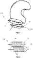
- the garment indicated schematically in figure 7 with the reference number 200 can be, for example, a motorcycle suit, or a jacket for motorcycle use.
- the garment can house the protective device in a respective pocket.
- the garment may house the protective device in an upper area of the torso, and/or in the collar.
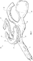
- the protection device comprises a plurality of inflatable elements 12, 13, 14, mutually superposed to form a multilayer structure.
- Each inflatable element 12, 13, 14 is shaped like a case and includes an inner chamber 3a, 3b.
- Each inflatable element 12, 13, 14 is adapted to assume substantially a first rest condition or deflated condition, and a second active condition or inflated condition.
- the inflating modalities of the inflatable element 12, 13, 14 will be described in the following description.
- the inflatable elements In inflated condition, the inflatable elements can leak out of the garment or remain protected inside a pocket.
- each inflatable element 12, 13, 14 is suitably cut into shape or generally shaped to protect, when in use, the torso of a user and the upper area under the helmet.
- a first inflatable element 12 has a shape with two front portions 17, 18 for the chest, two side wings 19, 20 for covering the shoulders of a user, and a spinal portion 21, designed to protect the user's backbone.
- a gas generator not visible in the drawings, in the example a gas cylinder under pressure, is included in the spinal portion 21 of the inflatable element, more preferably in an end region of the spinal portion 11.
- Portions 23, 24 connect the spinal portion 21 with the front portions 17, 18.
- the other two inflatable elements 13, 14 are smaller in size, shaped as "C" and occupy a neck area of a user, such as to position themselves under the helmet of a user, at least in inflated condition.
- the protection is offered by two or more of the inflatable elements 12, 13, 14, in the example all three, in an at least partially overlapped condition, so as to form a maximum thickness in the inflated condition of the protection device defined by the sum of the thickness of each inflatable element 12, 13, 14 in an inflated condition.
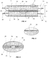
- the inflatable elements form a multilayer inflatable structure whose overall thickness or height H in inflated condition is the sum of the thicknesses of the three inflatable elements 12, 13, 14. This condition is visible in figures 4 and 6 .
- figure 4 is identified, by way of example, only the height corresponding to the sum of the height of the inflatable element 13 and of the height of the inflatable element 14.
- the protection device of figure 7 and figure 8 has the same characteristics and can be obtained by overlapping the two inflatable elements 13, 14.
- Each inflatable element 12, 13, 14 comprises a plurality of tie elements 5 distributed in the inner chamber 3a, 3b and permanently connected to respective portions of each inflatable element 12, 13, 14.
- tie element 5 means an element or entity having the function of holding together or constrained or stationary, being tensioned in tension, two or more parts of the inflatable element 12, 13, 14, at least when the latter is in an inflated condition.
- Figures 4 to 6 refer to the two inflatable elements 13 and 14 of smaller size, it being understood that the description applies to any combination of inflatable elements in an overlapped condition.
- the tie elements 5 are thread-like, and are flexible and inextensible elements. Therefore, they are appropriately sized so that, when the inflatable element 12, 13, 14 is in the rest condition, they are preferably not subjected to tensioning and are collapsed in the inner chamber 3, whereas when the inflatable element 12, 13, 14 is in inflated condition they are subjected to tension.
- each inflatable element 12, 13, 14 comprises a textile structure comprising the aforesaid tie elements 5 and two opposing meshes 28, 29, each of which internally lines, that is to say, on the inner chamber side 3a, 3b, a respective wall 25, 26.
- a textile structure formed by two meshes 28, 29 is arranged inside the area between the two walls 25, 26 and each mesh 28, 29 is preferably fixed to the respective wall 25, 26.
- each mesh 28, 29 is firmly fixed to the surface of the respective wall 15, 16, preferably by means of a glue film or glue layer.
- Each inflatable element can be made according to the technology described in WO2010/067288 A1 or WO2016/178143 or as described in the European application EP3167730A1 .
- the protection device is configured for inflating the two or more inflatable elements 12, 13 and 14 at least partly in an overlapped condition.
- a reciprocal bonding of the two walls 25, 26 is preferably provided, that is to say a zone of direct stable connection between two portions of walls 25 and 26, or between both walls in their entirety.
- the inflatable elements are prepared autonomously, and then joined once made, by connecting the walls.
- the gluing can be obtained by means of a layer acting as glue or adhesive, in the example a layer 35 of polyurethane glue (not thermoplastic), distributed on the outer side of a wall 25, 26 of an inflatable element 13 and on the opposite outer or facing layer of the wall of the other inflatable element 14.
- the surface extension of the layer 35 may be limited or limited to the surface extension of the walls 25, 26.
- the protection device 10, 110 is able to cooperate with suitable activation means operatively connected to a gas generator illustrated in the figures just as an illustration of a compressed cold gas cylinder.
- a gas generator illustrated in the figures just as an illustration of a compressed cold gas cylinder.
- the cylinder can be included in the garment.
- inflation means may comprise pyrotechnic or hybrid type gas generators or other types known to the state of the art.
- the protective device 10 provides that the gas cylinder is connected to the inflatable element 12 so as to send high pressure gases into this inflatable element. The gas then flows into the remaining inflatable elements 13, and 14. Holes 36, 37 for a fluid communication between the inflation chambers 3a, 3b are provided on the glued surfaces of the respective inflatable elements 12, 13 and 14. The gluing between the two surfaces of the inflatable elements allow to avoid excessive fluid losses and to control the passage of gas between the inflation chambers 3a, 3b.
- the holes 36, 37 are through holes and made in the mesh 28, 29 as well in the wall 25, 26 of the respective inflatable element 12, 13 and 14.
- the holes 36, 37 are suitably sized to allow inflation at adequate pressure and sufficient time for all the inflatable elements to be inflated.
- the protection device 110 of figures 7 and 8 which incorporates all the above characteristics, provides that the two inflatable elements 13 and 14 are only partially overlapped, to adapt to the space and to the condition of use.
- the two inflatable elements form a sort of step, or stepped profile.
- One of the two inflatable elements is placed under the helmet.
- the other of the two inflatable elements surrounds the helmet.
- the cylinder is connected to both the inflatable elements by means of a "Y" shaped pipe.
- a conduit is provided which has a branch with two branches towards the two or more inflatable elements. Each branch may have a different section to allow adjustment of the different gas pressure in the respective inflation chambers.
- the two inflatable elements are then separated fluidically, or fluidically independent, i.e. not in fluid communication.
- overpressure valves capable of passing the gas from an inflation chamber upon reaching a certain pressure at the other inflation chamber.
- the gas source can be controlled by hand by the user when he sees the danger, or by a control unit based on the detection of the status of the vehicle/pilot system; for example, said control unit can implement a fall prediction system that allows a timely identification of the fall event and a reliable prediction of this by means of accelerometric sensors integral with the pilot (or vehicle) and a processing unit of the signals produced by the sensors themselves.
- the aforesaid activation and inflation means can be integrated into the protection device 10, 110 according to the present invention or placed externally thereto.
Landscapes
- Engineering & Computer Science (AREA)
- Textile Engineering (AREA)
- Mechanical Engineering (AREA)
- Health & Medical Sciences (AREA)
- General Health & Medical Sciences (AREA)
- Physical Education & Sports Medicine (AREA)
- Otolaryngology (AREA)
- Professional, Industrial, Or Sporting Protective Garments (AREA)
Claims (11)
- Dispositif de protection (10, 110) pour la protection personnelle d'un utilisateur, ledit dispositif comprenant un premier élément gonflable (12, 13) ayant une chambre interne (3a) respective et un second élément gonflable (14) prévu avec une chambre interne (3b) respective, dans lequel chaque élément gonflable (12, 13, 14) est apte à adopter une condition de repos dégonflée et une condition active gonflée dans le cas d'une chute dudit utilisateur et/ou dans le cas d'un danger ou impact dudit utilisateur contre un obstacle, dans lequel chaque élément gonflable (12, 13, 14) comprend une première paroi (25) et une seconde paroi (26) opposées entre elles et raccordées le long d'un périmètre, une première maille (28) ou partie de maille, qui recouvre intérieurement au moins partiellement ladite première paroi (25), et une seconde maille (19) ou seconde partie de maille qui recouvre intérieurement au moins partiellement ladite seconde paroi (26), une pluralité d'éléments d'attache (5) ayant des extrémités (5a, 5b) respectivement fixées ou associées à ladite première maille (28) et à ladite seconde maille (29) et lesdits éléments d'attache (5) étant aptes à être dans une condition tendue lorsque l'élément gonflable respectif est dans la condition gonflée, dans lequel au moins dans ladite condition gonflée, ledit premier élément gonflable (12, 13) et ledit second élément gonflable (14) se chevauchent mutuellement et définissent une structure gonflable multicouche ; et caractérisé en ce que l'une entre la première paroi (25) et la seconde paroi (26) dudit premier élément gonflable (12, 13) est au moins partiellement fixée par adhérence à l'une entre la première paroi (25) et la seconde paroi (26) dudit second élément gonflable (14).
- Dispositif de protection (10, 110) selon la revendication 1, dans lequel une épaisseur de ladite structure gonflable est la somme d'une épaisseur dudit premier élément gonflable et de l'épaisseur dudit second élément gonflable.
- Dispositif de protection (10, 110) selon la revendication 1 ou 2, dans lequel ladite une entre la première paroi et la seconde paroi dudit premier élément gonflable et ladite une entre la première paroi et la seconde paroi dudit second élément gonflable sont prévues avec un trou débouchant de communication (36, 37) pour réaliser une communication de fluide entre les chambres internes des deux éléments gonflables.
- Dispositif de protection (10, 110) selon la revendication 3, dans lequel la maille (28) recouvrant ladite une entre la première paroi (25) et la seconde paroi (26) dudit premier élément gonflable (12, 13) et la maille (29) recouvrant ladite une entre la première paroi (25) et la seconde paroi (26) dudit second élément gonflable (14) sont prévues avec ledit trou débouchant de communication (36, 37) pour réaliser une communication de fluide entre le premier élément gonflable et le second élément gonflable.
- Dispositif de protection (10, 110) selon la revendication 4, dans lequel les trous débouchants de communication (36, 37) du premier élément gonflable (12, 13) et du second élément gonflable (14) sont partiellement superposés ou partiellement en chevauchement.
- Vêtement comprenant ou incorporant de manière solidaire ou associé avec un dispositif de protection (10, 110) selon l'une quelconque des revendications précédentes, ou vêtement qui est, ou coïncide avec un dispositif de protection (10, 110) selon l'une quelconque des revendications précédentes.
- Procédé pour fournir un dispositif de protection (10, 110) pour la protection personnelle d'un utilisateur au moyen d'au moins un premier élément gonflable (12, 13) et d'un second élément gonflable (14), dans lequel ledit procédé comprend l'étape suivante :
réaliser chaque élément gonflable (12, 13, 14) en fournissant une structure textile comprenant :une première maille (28) et une seconde maille (29), et une première paroi (25) et une seconde paroi (26) opposées entre elles et raccordées le long d'un périmètre, dans lequel la première maille (28) recouvre intérieurement au moins partiellement ladite première paroi (25) et la seconde maille (29) recouvre intérieurement au moins partiellement ladite seconde paroi (26) ;des éléments d'attache (5) ayant des extrémités fixées ou associées respectivement avec la première maille (28) et la seconde maille (29) de l'élément gonflable respectif, dans lequel lesdits éléments d'attache (5) sont au moins partiellement aptes à être dans une condition tendue lorsque l'élément gonflable est dans une condition gonflée ;superposer au moins partiellement le premier élément gonflable (12, 13) et le second élément gonflable (14) et fixer l'une entre la première paroi (25) et la seconde paroi (26) dudit premier élément gonflable (12, 13) adhérant au moins partiellement à l'une parmi la première paroi (25) et la seconde paroi (26) dudit second élément gonflable (14) ;ledit dispositif de protection (10, 110) étant configuré pour gonfler le premier élément gonflable (12, 13) et le second élément gonflable (14) afin de définir une structure gonflable, dans lequel les deux éléments gonflables (12, 13, 14) sont au moins partiellement superposés dans la condition gonflée. - Procédé selon la revendication 7, dans lequel, après avoir réalisé le premier élément gonflable (12, 13) et le second élément gonflable (14), le premier élément gonflable (12, 13) est percé pour obtenir au moins un premier trou de communication (36) et le second élément gonflable (14) est percé pour obtenir au moins un second trou de communication (37), dans lequel le premier trou de communication (36) est mis au moins partiellement en communication de fluide avec le second trou de communication (37).
- Procédé selon la revendication 8, dans lequel chacun parmi le premier trou de communication (36) et le second trou de communication (37) est un trou débouchant réalisé dans l'une entre la première paroi et la seconde paroi dudit premier élément gonflable (12, 13) et dans l'une entre la première paroi et la seconde paroi dudit second élément gonflable (14).
- Procédé selon la revendication 9, dans lequel chacun parmi le premier trou de communication et le second trou de communication est un trou débouchant réalisé dans l'une entre la première paroi et la seconde paroi dudit premier élément gonflable (12, 13) et la maille respective, et dans l'une entre la première paroi et la seconde paroi dudit second élément gonflable et la maille respective.
- Procédé selon l'une quelconque des revendications 8 à 10, dans lequel une couche de colle (35) est intercalée entre le premier élément gonflable et le second élément gonflable, au moins autour des trous de communication du premier élément gonflable (12, 13) et du second élément gonflable (14).
Applications Claiming Priority (1)
| Application Number | Priority Date | Filing Date | Title |
|---|---|---|---|
| IT102017000084843A IT201700084843A1 (it) | 2017-07-25 | 2017-07-25 | Dispositivo di protezione |
Publications (2)
| Publication Number | Publication Date |
|---|---|
| EP3434123A1 EP3434123A1 (fr) | 2019-01-30 |
| EP3434123B1 true EP3434123B1 (fr) | 2020-04-22 |
Family
ID=60990974
Family Applications (1)
| Application Number | Title | Priority Date | Filing Date |
|---|---|---|---|
| EP18185551.1A Active EP3434123B1 (fr) | 2017-07-25 | 2018-07-25 | Dispositif de protection |
Country Status (2)
| Country | Link |
|---|---|
| EP (1) | EP3434123B1 (fr) |
| IT (1) | IT201700084843A1 (fr) |
Cited By (1)
| Publication number | Priority date | Publication date | Assignee | Title |
|---|---|---|---|---|
| WO2022129528A1 (fr) | 2020-12-18 | 2022-06-23 | Alpinestars Research S.p.A. | Dispositif de protection à porter sur soi |
Families Citing this family (5)
| Publication number | Priority date | Publication date | Assignee | Title |
|---|---|---|---|---|
| JP7524755B2 (ja) * | 2020-12-16 | 2024-07-30 | 豊田合成株式会社 | 着用エアバッグ装置 |
| IT202100031829A1 (it) | 2021-12-20 | 2023-06-20 | D Air Lab S R L | Dispositivo di protezione personale |
| CN118434321A (zh) * | 2021-12-23 | 2024-08-02 | 奥托立夫开发公司 | 用于人的头部的保护装置 |
| IT202200010424A1 (it) | 2022-05-19 | 2023-11-19 | D Air Lab S R L | Dispositivo di protezione personale |
| DE102023102340A1 (de) * | 2023-01-31 | 2024-08-01 | Autoliv Development Ab | Tragbare Schutzvorrichtung |
Family Cites Families (6)
| Publication number | Priority date | Publication date | Assignee | Title |
|---|---|---|---|---|
| WO2006089144A1 (fr) * | 2005-02-18 | 2006-08-24 | Tk Holdings Inc. | Airbag (coussin gonflable) |
| EP2373188B1 (fr) * | 2008-12-09 | 2012-02-08 | Dainese S.p.A. | Vêtement conçu pour être associé à un dispositif destiné à la protection personnelle d'un utilisateur |
| EP2373190B1 (fr) * | 2008-12-09 | 2012-05-30 | Dainese S.p.A. | Dispositif de protection comprenant un élément gonflable |
| ITVR20130136A1 (it) * | 2013-06-12 | 2014-12-13 | Dainese Spa | Dispositivo di protezione personale. |
| ITVR20150074A1 (it) * | 2015-05-06 | 2016-11-06 | Dainese Spa | Dispositivo di protezione e metodo per realizzare tale dispositivo di protezione |
| ITUB20155497A1 (it) * | 2015-11-11 | 2017-05-11 | Dainese Spa | Dispositivo di protezione |
-
2017
- 2017-07-25 IT IT102017000084843A patent/IT201700084843A1/it unknown
-
2018
- 2018-07-25 EP EP18185551.1A patent/EP3434123B1/fr active Active
Non-Patent Citations (1)
| Title |
|---|
| None * |
Cited By (2)
| Publication number | Priority date | Publication date | Assignee | Title |
|---|---|---|---|---|
| WO2022129528A1 (fr) | 2020-12-18 | 2022-06-23 | Alpinestars Research S.p.A. | Dispositif de protection à porter sur soi |
| EP4262465A1 (fr) * | 2020-12-18 | 2023-10-25 | Alpinestars Research S.p.A. | Dispositif de protection à porter sur soi |
Also Published As
| Publication number | Publication date |
|---|---|
| EP3434123A1 (fr) | 2019-01-30 |
| IT201700084843A1 (it) | 2019-01-25 |
Similar Documents
| Publication | Publication Date | Title |
|---|---|---|
| EP3434123B1 (fr) | Dispositif de protection | |
| EP2373190B1 (fr) | Dispositif de protection comprenant un élément gonflable | |
| EP2621297B1 (fr) | Airbag adapté à la protection de la tête | |
| EP3432744B1 (fr) | Dispositif de protection | |
| WO2007138817A1 (fr) | Gilet de sauvetage gonflable | |
| EP3007573B1 (fr) | Dispositif de protection personnelle | |
| EP2956026B1 (fr) | Équipement de protection individuelle destiné à protéger un utilisateur | |
| US6678895B1 (en) | Protective garment, which is worn with shoulder pad having inflatable bladder, for firefighter or for emergency worker | |
| EP4197378B1 (fr) | Dispositif de protection personnelle | |
| EP3007572B1 (fr) | Dispositif de protection personnelle | |
| CN202980202U (zh) | 身体保护装置及具有该装置的衣服 | |
| EP4278917B1 (fr) | Dispositif de protection individuelle | |
| ES3014111T3 (en) | Protection device | |
| ITVR20090211A1 (it) | Dispositivo di protezione personale ed indumento incorporante tale dispositivo | |
| IT202300004077A1 (it) | Dispositivo di supporto e protezione per l’area perineale-ischiatica di un guidatore utilizzabile in un pantalone o tuta da ciclismo. | |
| ITMI970569U1 (it) | Indumento protettivo | |
| ITVR20090078A1 (it) | Dispositivo di protezione includente un elemento gonfiabile. |
Legal Events
| Date | Code | Title | Description |
|---|---|---|---|
| PUAI | Public reference made under article 153(3) epc to a published international application that has entered the european phase |
Free format text: ORIGINAL CODE: 0009012 |
|
| STAA | Information on the status of an ep patent application or granted ep patent |
Free format text: STATUS: THE APPLICATION HAS BEEN PUBLISHED |
|
| AK | Designated contracting states |
Kind code of ref document: A1 Designated state(s): AL AT BE BG CH CY CZ DE DK EE ES FI FR GB GR HR HU IE IS IT LI LT LU LV MC MK MT NL NO PL PT RO RS SE SI SK SM TR |
|
| AX | Request for extension of the european patent |
Extension state: BA ME |
|
| RAP1 | Party data changed (applicant data changed or rights of an application transferred) |
Owner name: DAINESE S.P.A. |
|
| STAA | Information on the status of an ep patent application or granted ep patent |
Free format text: STATUS: REQUEST FOR EXAMINATION WAS MADE |
|
| RAP1 | Party data changed (applicant data changed or rights of an application transferred) |
Owner name: DAINESE S.P.A. |
|
| 17P | Request for examination filed |
Effective date: 20190729 |
|
| RBV | Designated contracting states (corrected) |
Designated state(s): AL AT BE BG CH CY CZ DE DK EE ES FI FR GB GR HR HU IE IS IT LI LT LU LV MC MK MT NL NO PL PT RO RS SE SI SK SM TR |
|
| GRAP | Despatch of communication of intention to grant a patent |
Free format text: ORIGINAL CODE: EPIDOSNIGR1 |
|
| STAA | Information on the status of an ep patent application or granted ep patent |
Free format text: STATUS: GRANT OF PATENT IS INTENDED |
|
| RIC1 | Information provided on ipc code assigned before grant |
Ipc: D04B 1/22 20060101ALN20191023BHEP Ipc: A41D 31/00 20190101ALN20191023BHEP Ipc: A41D 13/05 20060101ALI20191023BHEP Ipc: A41D 13/018 20060101AFI20191023BHEP Ipc: B32B 5/26 20060101ALI20191023BHEP Ipc: B60R 21/2338 20110101ALI20191023BHEP Ipc: B60R 21/233 20060101ALI20191023BHEP Ipc: B62J 27/00 20060101ALI20191023BHEP Ipc: B60R 21/235 20060101ALI20191023BHEP Ipc: A63B 71/08 20060101ALN20191023BHEP |
|
| RIC1 | Information provided on ipc code assigned before grant |
Ipc: B62J 27/00 20060101ALI20191030BHEP Ipc: D04B 1/22 20060101ALN20191030BHEP Ipc: A63B 71/08 20060101ALN20191030BHEP Ipc: B60R 21/2338 20110101ALI20191030BHEP Ipc: B32B 5/26 20060101ALI20191030BHEP Ipc: A41D 13/05 20060101ALI20191030BHEP Ipc: B60R 21/233 20060101ALI20191030BHEP Ipc: A41D 13/018 20060101AFI20191030BHEP Ipc: B60R 21/235 20060101ALI20191030BHEP Ipc: A41D 31/00 20190101ALN20191030BHEP |
|
| INTG | Intention to grant announced |
Effective date: 20191122 |
|
| GRAS | Grant fee paid |
Free format text: ORIGINAL CODE: EPIDOSNIGR3 |
|
| GRAA | (expected) grant |
Free format text: ORIGINAL CODE: 0009210 |
|
| STAA | Information on the status of an ep patent application or granted ep patent |
Free format text: STATUS: THE PATENT HAS BEEN GRANTED |
|
| AK | Designated contracting states |
Kind code of ref document: B1 Designated state(s): AL AT BE BG CH CY CZ DE DK EE ES FI FR GB GR HR HU IE IS IT LI LT LU LV MC MK MT NL NO PL PT RO RS SE SI SK SM TR |
|
| REG | Reference to a national code |
Ref country code: CH Ref legal event code: EP |
|
| REG | Reference to a national code |
Ref country code: IE Ref legal event code: FG4D |
|
| REG | Reference to a national code |
Ref country code: DE Ref legal event code: R096 Ref document number: 602018003939 Country of ref document: DE |
|
| REG | Reference to a national code |
Ref country code: AT Ref legal event code: REF Ref document number: 1258901 Country of ref document: AT Kind code of ref document: T Effective date: 20200515 |
|
| REG | Reference to a national code |
Ref country code: LT Ref legal event code: MG4D |
|
| REG | Reference to a national code |
Ref country code: NL Ref legal event code: MP Effective date: 20200422 |
|
| PG25 | Lapsed in a contracting state [announced via postgrant information from national office to epo] |
Ref country code: IS Free format text: LAPSE BECAUSE OF FAILURE TO SUBMIT A TRANSLATION OF THE DESCRIPTION OR TO PAY THE FEE WITHIN THE PRESCRIBED TIME-LIMIT Effective date: 20200822 Ref country code: FI Free format text: LAPSE BECAUSE OF FAILURE TO SUBMIT A TRANSLATION OF THE DESCRIPTION OR TO PAY THE FEE WITHIN THE PRESCRIBED TIME-LIMIT Effective date: 20200422 Ref country code: GR Free format text: LAPSE BECAUSE OF FAILURE TO SUBMIT A TRANSLATION OF THE DESCRIPTION OR TO PAY THE FEE WITHIN THE PRESCRIBED TIME-LIMIT Effective date: 20200723 Ref country code: NO Free format text: LAPSE BECAUSE OF FAILURE TO SUBMIT A TRANSLATION OF THE DESCRIPTION OR TO PAY THE FEE WITHIN THE PRESCRIBED TIME-LIMIT Effective date: 20200722 Ref country code: NL Free format text: LAPSE BECAUSE OF FAILURE TO SUBMIT A TRANSLATION OF THE DESCRIPTION OR TO PAY THE FEE WITHIN THE PRESCRIBED TIME-LIMIT Effective date: 20200422 Ref country code: SE Free format text: LAPSE BECAUSE OF FAILURE TO SUBMIT A TRANSLATION OF THE DESCRIPTION OR TO PAY THE FEE WITHIN THE PRESCRIBED TIME-LIMIT Effective date: 20200422 Ref country code: LT Free format text: LAPSE BECAUSE OF FAILURE TO SUBMIT A TRANSLATION OF THE DESCRIPTION OR TO PAY THE FEE WITHIN THE PRESCRIBED TIME-LIMIT Effective date: 20200422 Ref country code: PT Free format text: LAPSE BECAUSE OF FAILURE TO SUBMIT A TRANSLATION OF THE DESCRIPTION OR TO PAY THE FEE WITHIN THE PRESCRIBED TIME-LIMIT Effective date: 20200824 |
|
| REG | Reference to a national code |
Ref country code: AT Ref legal event code: MK05 Ref document number: 1258901 Country of ref document: AT Kind code of ref document: T Effective date: 20200422 |
|
| PG25 | Lapsed in a contracting state [announced via postgrant information from national office to epo] |
Ref country code: BG Free format text: LAPSE BECAUSE OF FAILURE TO SUBMIT A TRANSLATION OF THE DESCRIPTION OR TO PAY THE FEE WITHIN THE PRESCRIBED TIME-LIMIT Effective date: 20200722 Ref country code: HR Free format text: LAPSE BECAUSE OF FAILURE TO SUBMIT A TRANSLATION OF THE DESCRIPTION OR TO PAY THE FEE WITHIN THE PRESCRIBED TIME-LIMIT Effective date: 20200422 Ref country code: LV Free format text: LAPSE BECAUSE OF FAILURE TO SUBMIT A TRANSLATION OF THE DESCRIPTION OR TO PAY THE FEE WITHIN THE PRESCRIBED TIME-LIMIT Effective date: 20200422 Ref country code: RS Free format text: LAPSE BECAUSE OF FAILURE TO SUBMIT A TRANSLATION OF THE DESCRIPTION OR TO PAY THE FEE WITHIN THE PRESCRIBED TIME-LIMIT Effective date: 20200422 |
|
| PG25 | Lapsed in a contracting state [announced via postgrant information from national office to epo] |
Ref country code: AL Free format text: LAPSE BECAUSE OF FAILURE TO SUBMIT A TRANSLATION OF THE DESCRIPTION OR TO PAY THE FEE WITHIN THE PRESCRIBED TIME-LIMIT Effective date: 20200422 |
|
| REG | Reference to a national code |
Ref country code: DE Ref legal event code: R097 Ref document number: 602018003939 Country of ref document: DE |
|
| PG25 | Lapsed in a contracting state [announced via postgrant information from national office to epo] |
Ref country code: DK Free format text: LAPSE BECAUSE OF FAILURE TO SUBMIT A TRANSLATION OF THE DESCRIPTION OR TO PAY THE FEE WITHIN THE PRESCRIBED TIME-LIMIT Effective date: 20200422 Ref country code: AT Free format text: LAPSE BECAUSE OF FAILURE TO SUBMIT A TRANSLATION OF THE DESCRIPTION OR TO PAY THE FEE WITHIN THE PRESCRIBED TIME-LIMIT Effective date: 20200422 Ref country code: ES Free format text: LAPSE BECAUSE OF FAILURE TO SUBMIT A TRANSLATION OF THE DESCRIPTION OR TO PAY THE FEE WITHIN THE PRESCRIBED TIME-LIMIT Effective date: 20200422 Ref country code: CZ Free format text: LAPSE BECAUSE OF FAILURE TO SUBMIT A TRANSLATION OF THE DESCRIPTION OR TO PAY THE FEE WITHIN THE PRESCRIBED TIME-LIMIT Effective date: 20200422 Ref country code: RO Free format text: LAPSE BECAUSE OF FAILURE TO SUBMIT A TRANSLATION OF THE DESCRIPTION OR TO PAY THE FEE WITHIN THE PRESCRIBED TIME-LIMIT Effective date: 20200422 Ref country code: IT Free format text: LAPSE BECAUSE OF FAILURE TO SUBMIT A TRANSLATION OF THE DESCRIPTION OR TO PAY THE FEE WITHIN THE PRESCRIBED TIME-LIMIT Effective date: 20200422 Ref country code: SM Free format text: LAPSE BECAUSE OF FAILURE TO SUBMIT A TRANSLATION OF THE DESCRIPTION OR TO PAY THE FEE WITHIN THE PRESCRIBED TIME-LIMIT Effective date: 20200422 Ref country code: EE Free format text: LAPSE BECAUSE OF FAILURE TO SUBMIT A TRANSLATION OF THE DESCRIPTION OR TO PAY THE FEE WITHIN THE PRESCRIBED TIME-LIMIT Effective date: 20200422 |
|
| PG25 | Lapsed in a contracting state [announced via postgrant information from national office to epo] |
Ref country code: PL Free format text: LAPSE BECAUSE OF FAILURE TO SUBMIT A TRANSLATION OF THE DESCRIPTION OR TO PAY THE FEE WITHIN THE PRESCRIBED TIME-LIMIT Effective date: 20200422 Ref country code: SK Free format text: LAPSE BECAUSE OF FAILURE TO SUBMIT A TRANSLATION OF THE DESCRIPTION OR TO PAY THE FEE WITHIN THE PRESCRIBED TIME-LIMIT Effective date: 20200422 Ref country code: MC Free format text: LAPSE BECAUSE OF FAILURE TO SUBMIT A TRANSLATION OF THE DESCRIPTION OR TO PAY THE FEE WITHIN THE PRESCRIBED TIME-LIMIT Effective date: 20200422 |
|
| PLBE | No opposition filed within time limit |
Free format text: ORIGINAL CODE: 0009261 |
|
| STAA | Information on the status of an ep patent application or granted ep patent |
Free format text: STATUS: NO OPPOSITION FILED WITHIN TIME LIMIT |
|
| 26N | No opposition filed |
Effective date: 20210125 |
|
| REG | Reference to a national code |
Ref country code: BE Ref legal event code: MM Effective date: 20200731 |
|
| PG25 | Lapsed in a contracting state [announced via postgrant information from national office to epo] |
Ref country code: LU Free format text: LAPSE BECAUSE OF NON-PAYMENT OF DUE FEES Effective date: 20200725 |
|
| PG25 | Lapsed in a contracting state [announced via postgrant information from national office to epo] |
Ref country code: BE Free format text: LAPSE BECAUSE OF NON-PAYMENT OF DUE FEES Effective date: 20200731 Ref country code: SI Free format text: LAPSE BECAUSE OF FAILURE TO SUBMIT A TRANSLATION OF THE DESCRIPTION OR TO PAY THE FEE WITHIN THE PRESCRIBED TIME-LIMIT Effective date: 20200422 |
|
| PG25 | Lapsed in a contracting state [announced via postgrant information from national office to epo] |
Ref country code: IE Free format text: LAPSE BECAUSE OF NON-PAYMENT OF DUE FEES Effective date: 20200725 |
|
| REG | Reference to a national code |
Ref country code: CH Ref legal event code: PL |
|
| PG25 | Lapsed in a contracting state [announced via postgrant information from national office to epo] |
Ref country code: LI Free format text: LAPSE BECAUSE OF NON-PAYMENT OF DUE FEES Effective date: 20210731 Ref country code: CH Free format text: LAPSE BECAUSE OF NON-PAYMENT OF DUE FEES Effective date: 20210731 |
|
| PG25 | Lapsed in a contracting state [announced via postgrant information from national office to epo] |
Ref country code: TR Free format text: LAPSE BECAUSE OF FAILURE TO SUBMIT A TRANSLATION OF THE DESCRIPTION OR TO PAY THE FEE WITHIN THE PRESCRIBED TIME-LIMIT Effective date: 20200422 Ref country code: MT Free format text: LAPSE BECAUSE OF FAILURE TO SUBMIT A TRANSLATION OF THE DESCRIPTION OR TO PAY THE FEE WITHIN THE PRESCRIBED TIME-LIMIT Effective date: 20200422 Ref country code: CY Free format text: LAPSE BECAUSE OF FAILURE TO SUBMIT A TRANSLATION OF THE DESCRIPTION OR TO PAY THE FEE WITHIN THE PRESCRIBED TIME-LIMIT Effective date: 20200422 |
|
| PG25 | Lapsed in a contracting state [announced via postgrant information from national office to epo] |
Ref country code: MK Free format text: LAPSE BECAUSE OF FAILURE TO SUBMIT A TRANSLATION OF THE DESCRIPTION OR TO PAY THE FEE WITHIN THE PRESCRIBED TIME-LIMIT Effective date: 20200422 |
|
| PGFP | Annual fee paid to national office [announced via postgrant information from national office to epo] |
Ref country code: GB Payment date: 20230721 Year of fee payment: 6 |
|
| GBPC | Gb: european patent ceased through non-payment of renewal fee |
Effective date: 20240725 |
|
| PG25 | Lapsed in a contracting state [announced via postgrant information from national office to epo] |
Ref country code: GB Free format text: LAPSE BECAUSE OF NON-PAYMENT OF DUE FEES Effective date: 20240725 |
|
| PGFP | Annual fee paid to national office [announced via postgrant information from national office to epo] |
Ref country code: DE Payment date: 20250722 Year of fee payment: 8 |
|
| PGFP | Annual fee paid to national office [announced via postgrant information from national office to epo] |
Ref country code: FR Payment date: 20250725 Year of fee payment: 8 |