EP3434403B1 - Station de travail - Google Patents
Station de travail Download PDFInfo
- Publication number
- EP3434403B1 EP3434403B1 EP17183824.6A EP17183824A EP3434403B1 EP 3434403 B1 EP3434403 B1 EP 3434403B1 EP 17183824 A EP17183824 A EP 17183824A EP 3434403 B1 EP3434403 B1 EP 3434403B1
- Authority
- EP
- European Patent Office
- Prior art keywords
- expandable
- back wall
- work
- workstation
- workstation according
- Prior art date
- Legal status (The legal status is an assumption and is not a legal conclusion. Google has not performed a legal analysis and makes no representation as to the accuracy of the status listed.)
- Active
Links
Images


Classifications
-
- B—PERFORMING OPERATIONS; TRANSPORTING
- B23—MACHINE TOOLS; METAL-WORKING NOT OTHERWISE PROVIDED FOR
- B23D—PLANING; SLOTTING; SHEARING; BROACHING; SAWING; FILING; SCRAPING; LIKE OPERATIONS FOR WORKING METAL BY REMOVING MATERIAL, NOT OTHERWISE PROVIDED FOR
- B23D47/00—Sawing machines or sawing devices working with circular saw blades, characterised only by constructional features of particular parts
- B23D47/02—Sawing machines or sawing devices working with circular saw blades, characterised only by constructional features of particular parts of frames; of guiding arrangements for work-table or saw-carrier
- B23D47/025—Sawing machines or sawing devices working with circular saw blades, characterised only by constructional features of particular parts of frames; of guiding arrangements for work-table or saw-carrier of tables
-
- B—PERFORMING OPERATIONS; TRANSPORTING
- B23—MACHINE TOOLS; METAL-WORKING NOT OTHERWISE PROVIDED FOR
- B23B—TURNING; BORING
- B23B31/00—Chucks; Expansion mandrels; Adaptations thereof for remote control
- B23B31/02—Chucks
- B23B31/10—Chucks characterised by the retaining or gripping devices or their immediate operating means
- B23B31/12—Chucks with simultaneously-acting jaws, whether or not also individually adjustable
- B23B31/1207—Chucks with simultaneously-acting jaws, whether or not also individually adjustable moving obliquely to the axis of the chuck in a plane containing this axis
- B23B31/1238—Jaws movement actuated by a nut with conical screw-thread
-
- B—PERFORMING OPERATIONS; TRANSPORTING
- B25—HAND TOOLS; PORTABLE POWER-DRIVEN TOOLS; MANIPULATORS
- B25H—WORKSHOP EQUIPMENT, e.g. FOR MARKING-OUT WORK; STORAGE MEANS FOR WORKSHOPS
- B25H1/00—Work benches; Portable stands or supports for positioning portable tools or work to be operated on thereby
- B25H1/10—Work benches; Portable stands or supports for positioning portable tools or work to be operated on thereby with provision for adjusting holders for tool or work
-
- B—PERFORMING OPERATIONS; TRANSPORTING
- B25—HAND TOOLS; PORTABLE POWER-DRIVEN TOOLS; MANIPULATORS
- B25H—WORKSHOP EQUIPMENT, e.g. FOR MARKING-OUT WORK; STORAGE MEANS FOR WORKSHOPS
- B25H1/00—Work benches; Portable stands or supports for positioning portable tools or work to be operated on thereby
- B25H1/14—Work benches; Portable stands or supports for positioning portable tools or work to be operated on thereby with provision for adjusting the bench top
-
- B—PERFORMING OPERATIONS; TRANSPORTING
- B25—HAND TOOLS; PORTABLE POWER-DRIVEN TOOLS; MANIPULATORS
- B25H—WORKSHOP EQUIPMENT, e.g. FOR MARKING-OUT WORK; STORAGE MEANS FOR WORKSHOPS
- B25H1/00—Work benches; Portable stands or supports for positioning portable tools or work to be operated on thereby
- B25H1/20—Work benches; Portable stands or supports for positioning portable tools or work to be operated on thereby with provision for shielding the work area
-
- B—PERFORMING OPERATIONS; TRANSPORTING
- B23—MACHINE TOOLS; METAL-WORKING NOT OTHERWISE PROVIDED FOR
- B23B—TURNING; BORING
- B23B2231/00—Details of chucks, toolholder shanks or tool shanks
- B23B2231/52—Chucks with means to loosely retain the tool or workpiece in the unclamped position
Definitions
- the present invention relates to a mobile workstation, e.g. for use in cutting a workpiece.
- a mobile workstation e.g. for use in cutting a workpiece.
- Such a mobile workstation is disclosed in DE8601410 U1 .
- a cutting workstation station is a designated area for cutting a workpiece such as a metal beam or a wooden plank.
- a mobile workstation allows the user to transfer the workstation to different construction locations. Mobile workstations may not be able to move in many construction sites due to their size. The size of the workstation also restricts the available number of cutting tools that can be used in the workstation.
- Optimising a mobile workstation can lead to more flexibility in accessing different locations and enabling a greater variety of tools to be used.
- a first aspect of the invention provides a mobile workstation comprising:
- the expandable portion of the mobile workstation increases the available space in the cutting zone to accommodate a larger cutting tool such as a chop saw or a mitre saw.
- the expandable portion of the mobile workstation also provides an additional benefit.
- the depth of the cutting zone may be less than the width of standard doorways. In one example the depth of the cutting zone in the non-expanded configuration is less than or equal to 82 cm. In another example the depth of the cutting zone in the non-expanded configuration is less than or equal to 77.9 cm. In another example the depth of the cutting zone in the non-expanded configuration is between 72 cm and 82 cm. Therefore, the workstation can fit through doorways. This provides a workstation which is sufficiently small to be moved through constrained spaces such as doorways in the non-expanded configuration yet allows larger cutting tools to be used that would otherwise not be accommodated without the expandable portion.
- the expandable part of the back wall and the expandable part of the work-surface may be coupled to move together. With such an arrangement gaps between the expandable part of the back wall and the expandable part of the work-surface are eliminated or covered. Therefore the expandable part can provide a cutting zone which offers noise cancellation and absorption benefits, and does not allow dust or swarf from the cutting operation to escape.
- the expandable part of the work-surface may be arranged in sliding configuration with the non-expandable part of the work-surface. With such an arrangement the depth of work-surface is arranged to vary.
- the expandable part of the back wall may be pivotably coupled to the non-expandable part of the back wall. With such an arrangement the angle between the expandable part of the back wall and the non-expandable part of the back wall can be modified to enable the depth of the cutting zone to vary.
- Such variations in the expandable part of the work-surface and/or the expandable part of the back wall allow the workstation to move through small spaces when in the non-expanded configuration and also enables bigger tools to be used when in the expanded configuration.
- the expandable portion may include sidewalls connecting between the expandable part of the back wall and the expandable part of the work-surface. With such an arrangement the sides of the expandable portion provide an enclosed cutting zone which offers noise cancellation and absorption benefits, and does not allow dust or swarf from the cutting operation to escape when the expandable portion is in the expanded configuration.
- the workstation may further comprise one or more stop members to limit the movement of the expandable portion.
- the expandable portion may include one or more guide members to coordinate movement of the expandable part of the back wall and the expandable part of the work-surface between the expanded and non-expanded configurations.
- the one or more guide members ensure that the expandable part of the back wall and the expandable part of the work-surface are constrained for movement along a predetermined path. Therefore the parts are not movable in a direction other than an intended direction of movement or beyond their limits.
- the guide member may comprise a pin movable within a slot.
- the pin may be a male-female screw coupled to the expandable part of the work-surface and the slot may be arranged on the expandable part of the back wall.
- the expandable portion may comprise a handle connected to a lever.
- the lever may be connected to the pin.
- the expandable portion may further comprise a nested insert having an opening towards the cutting zone.
- the nested insert provides an area for swarf collection.
- the nested insert also offers increased reinforcement of the back wall of the cutting zone.
- the nested insert may have an inclined back wall which sits against the expandable part of the back wall when in the expanded configuration and which may form a gap with the expandable part of the back wall when in the non-expanded configuration.
- the inclined back wall of the nested insert provides support to the expandable part of the back wall when in the expanded configuration.
- the inclined back wall of the nested insert supports part of the weight of the expandable part of the back wall and therefore stops the expandable part of the back wall moving inadvertently to the non-expanded configuration.
- the nested insert may have a base which rests upon the expandable part of the work-surface. Such an arrangement enables the nested insert to be movable with the expandable portion and also offers reinforcement of the cutting zone.
- the expandable portion may further comprise a swarf disposal aperture.
- the swarf disposal aperture allows dust or swarf from the cutting operation to be easily disposed of from the work-surface.
- the nested insert may further comprise a second swarf disposal aperture which is located in the swarf disposal aperture in the expandable part of the work-surface.
- the depth of the cutting zone may increase by up to 30% between the non-expanded and the expanded configurations.
- a workstation may further comprise lockable castor wheels.
- the lockable castor wheels make the workstation mobile and enable the user to move and use the workstation in different locations.
- the workstation may be a cutting-tool workstation.
- a further aspect of the invention provides a workstation supporting arm for a mobile cutting workstation, the supporting arm comprises:
- the reconfigurable head eliminates or significantly reduces the need for separate tools to be fitted and removed from the workstation when a different configuration or a different tool is required to support the workpiece.
- the head rotation axis allows to easily change between different configurations by switching between the tools that rotate around the rotation axis.
- the head may further comprise a fixing member to engage one or more of the tools in a position. This ensures that one or more of the tools can be securely engaged at a position that would serve at least one of the configurations.
- the substantially planar workpiece support surface may comprise a friction surface. If a user applies a force that overcomes the friction between the friction surface and the workpiece, the user can change the workpiece position.
- the friction provide by the friction surface may be selected according to user requirements.
- the tool may be selected according to the shape of different workpieces.
- a workpiece formed from a square tube of material can be supported by the substantially planar surface.
- a workpiece formed from a circular tube of material can be supported by the notched surface, e.g. having a supporting shoulder.
- the attachment structure may engage with an adjustment structure on the workstation to adjust the head position relative to the workstation.
- the adjustment structure may have a handle or other mechanism to release the head for movement relative to the workstation and to fix the position of the head relative to the workstation so as to vary the distance between the arm and workstation.
- One of the handles may adjust a height of the arm in relationship to the workstation.
- the workstation supporting arm can be utilized in any mobile cutting workstation having a work-surface and a cabinet to at least partially surround the work-surface to define a cutting-zone.
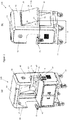
- FIGs 1a and 1b present an embodiment of a mobile workstation 100 in a non-expanded configuration.
- the mobile workstation 100 has a work-surface 60 and a cabinet 11 enclosing a cutting zone 15 for cutting workpieces such as metal beams or wooden planks.
- a cutting tool such as a chop saw or a mitre saw can be mounted on the work-surface 60 to perform cutting operations.
- the work-surface 60 is covered by an anti-static rubber mat to reduce hard-arm vibration during the cutting operation.
- the cutting zone 15 has a width W and a depth D.
- the width W of the cutting zone is between 104 cm and 124 cm. In the non-expanded configuration the depth D is less than a standard doorway width).
- the depth D of the cutting zone 15 in the non-expanded configuration is less than or equal to 82 cm. In another embodiment the depth D of the cutting zone 15 in the non-expanded configuration is less than or equal to 77.9 cm. In another embodiment the depth D of the cutting zone in the non-expanded configuration is between 72 cm and 82 cm.
- the mobile workstation 100 has four lockable castor wheels 77 that enable movement of the workstation to different locations.
- the cabinet 11 has a back wall 10, cabinet sidewalls 40, a front cover 45, a cabinet roof 50 and a modesty panel 55.
- the modesty panel 55 provides locators and cover over fastenings (not shown) which are used to attach a light housing (not shown) which is internal to the unit.
- the back wall 10, the cabinet sidewalls 40, the front cover 45 and the cabinet roof 50 have their sides facing towards the cutting zone 15 covered by sound deadening foam to reduce noise pollution.
- the cabinet 11 may also comprise PVC curtains to reduce noise and contain debris and sparks flying away from the cutting zone 15. The curtains may be adapted at the cabinet sidewalls and/or the front cover 45.
- a security cabinet 68 positioned beneath the work-surface 60, has a first door 62 and a second door 64 to provide access inside the security cabinet 68.
- the security cabinet 68 can be used to store tools and fittings.
- the mobile workstation 100 has an expandable portion 21 to enable expansion of cutting zone 15 depth D and allow large cutting tools to be used.
- the expandable portion 21 has an expandable back wall part 20, expandable sidewall parts 25, an expandable work-surface part 90, expandable work-surface sidewall parts 92 and a nested insert 80.
- the expandable work-surface part 90 is arranged to slide on the work-surface 60 to vary the depth D of the cutting zone 15.
- the expandable back wall part 20 pivotably couples to the non-expandable part of the back wall 10 through a hinge 30.
- the hinge 30 is a piano hinge.
- the hinge 30 couples to the expandable back wall part 20 and to the non-expandable part of the back wall 10.
- the nested insert 80 has a nested insert base 85, a nested insert back wall 87, nested insert sidewalls 86, a nested insert opening 88 towards the cutting zone 15, a swarf disposal aperture 82 and a nested insert swarf disposal tube 81.
- the swarf disposal aperture 82 allows swarf to be disposed of through the nested insert swarf disposal tube 81 into a suitable container placed below (not shown).
- the mobile workstation 100 is made from subassemblies comprising folded panels which slot into each other to improve strength.
- the mobile workstation 100 has a side light source 75, one or more sockets 70,two workpiece supporting arms 71 and a light switch (not visible in the figure).
- the side light source 75 is positioned so that a light beam angle is in a direction that would not cast a shadow upon a user of the workstation.
- the socket 70 provides 110V power supply.
- the socket 70 is used for plugging in tools and equipment and is positioned so as to provide improved safety and access to the user.
- Each of the supporting arms 71 is extendable along the width W of the workstation 100 to accommodate handling different lengths of workpieces for the cutting operation.
- Each of the supporting arms 71 has adjustable height to adjust to different tools used in the cutting operation.
- the adjustable height of the supporting arms 71 can also accommodate any unevenness on surfaces that the workstation is located.
- Each of the supporting arms 71 comprises a first tube with a fist channel, not visible in the figure, passing below the work-surface 60 along the width W of the workstation.
- Each of the supporting arms 71 also comprises a second tube 72 having a second channel 79.
- Each of the supporting arms 71 has a first rotatable handle 76 to adjust the supporting arm 71 extension along the width W of the workstation 100.
- the first rotatable handle 76 is movable between different positions within the first channel of the first tube. The user rotates the first rotatable handle 76 to vary the distance between the work-surface 60 and the supporting arm 71 and extend the first tube along the width W of the workstation 100.
- each of the supporting arms 71 is adjustable by a second rotatable handle 73.
- the second rotatable handle 73 is movable between different positions within the second channel 79 of the second tube 72.
- the user rotates the handle 73 to adjust the height of the tube 72, and thus the height of the supporting arm 71.
- a rack and pinion mechanism are used for both the first rotatable handle 76 and the second rotatable handle 73.
- different embodiments may employ different mechanisms for extension and height adjustment of each supporting arm 71.
- Each of the supporting arms 71 have tools such as a roller 74, a blade 67, a substantially planar support surface 66 or a notched support surface having support shoulder 78 to support workpieces in different ways.
- tools such as a roller 74, a blade 67, a substantially planar support surface 66 or a notched support surface having support shoulder 78 to support workpieces in different ways.
- a detailed description of the support structures follows in relation to Figures 5 and 6 .
- Figures 2a and 2b show the mobile workstation 100 at an expanded configuration.
- the expandable work-surface part 90 slides on the work-surface 60, while the expandable back wall part 20 pivots around the non-expandable part of the back wall 10.
- This increases the depth D of the cutting zone 15 by up to 30% compared to the non-expanded configuration described in Figures 1a and 1b .
- This arrangement provides more space for large cutting tools such as chop saws and mitre saws which would otherwise be unable to fit within the cutting zone 15.
- the nested insert back wall 87 sits against the expandable back wall part 20. This enables support of the expandable back wall part 20 in the expanded configuration and minimises the risk of the expandable back wall part 20 inadvertently collapsing to the non-expanded configuration.
- Guide members coordinate the movement between the expanded and the non-expanded configuration.
- Each side of the expandable work-surface sidewalls 92 couples to a pin 26.
- the pins 26 slide within slots 27 formed at each side the expandable sidewall parts 25 and act as guide members.
- each pin is a male-female bolt.
- the pins 26 and the slots 27 also acts as stops to limit the movement of the expandable portion 21.
- Figures 3a and 3b illustrate the pins 26 and slots 27 in more detail in the expanded configuration of the expandable portion 21.
- Figure 3a illustrates the expandable portion 21 and the nested insert 80 in the expanded configuration
- Figure 3b illustrates the expandable portion 21 without a nested insert in the expanded configuration.
- the pins 26 sit at the top part of the slot 27 and the expandable work-surface part 90 is perpendicular to the expandable back wall part 20.
- the pins 26 sit at the bottom part of the slot 27 as illustrated in Figures 3a and 3b .
- the work-surface 60 has an aperture 65 or socket for plugging in tools and equipment providing easy access.
- an air extraction unit is placed within the security cabinet 68 and is connected through cabling passing through the aperture 65 with an extraction duct (not shown) sitting around the modesty panel 55.
- the extraction duct creates a clear air curtain in front of the user of the workstation.
- the expandable work-surface part 90 comprises a work-surface swarf disposal aperture 83.
- the nested insert swarf disposal aperture 82 is located in the work-surface swarf disposal aperture 83.
- Figure 4 is an exploded view of the expandable portion 21 without the nested insert 80.
- the expandable portion 21 has engagement levers 23 engaged through the pins 27 with each of the expandable sidewall parts 25.
- Each of the levers 23 has handles 42 to enable the user to control lever movement.
- the expandable portion 21 moves to the expanded configuration.
- the handle 42 in the opposite direction (i.e. forwards and/or upwards) the expandable portion 21 moves to the non-expanded configuration.
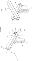
- FIGS 5 and 6 illustrate the supporting arm 71 for positioning and handling workpieces.
- the supporting arm 71 comprises different supporting tools, such as the roller 74 and a revolving member 61.
- the supporting arm 71 has different configurations to enable various support arrangements and handling of different workpieces.
- the supporting arm 71 has a rotatable axis 99 and a pair of roller axis ends 97 arranged at each end of the axis 99.
- the roller 74 and the revolving member 61 are rotatable around the axis 99.
- the roller 74 is an open-ended spring axle roller.
- the revolving member 61 has a rim 63, a supporting base 66 and a pair of lugs 98.
- the lugs 98 enable rotatable connection of the revolving member 61 to the axis ends 97.
- the supporting arm 71 comprises stop pins 96 arranged at each side of the arm to fix the position of the revolving member 61.
- Each of the lugs 98 has a first lock slot 94 and a second lock slot 95. When none of the slots 94 or 95 are engaged with the stop pins 96, the revolving member leans towards the second tube 72.
- Figure 5b shows the arm 71 at a sliding configuration.
- a square tube workpiece 93 is slidably supported by the roller 74 and the rim 63.
- the user can slide the square tube workpiece 93 along its longitudinal axis using the roller 74.
- Rotation of the roller 74 around the axis 99 allows a sliding movement of the square tube workpiece 93, but stops the square tube workpiece 93 from moving in directions that could cause problems during the cutting operation.
- each of the first slots 94 are engaged by stop pins 96 and the supporting arm 71 is configured at a resting configuration.
- the square tube workpiece 93 is supported by a friction surface 69. The user can move the square tube workpiece 93 along its longitudinal axis, however due to the friction between the friction surface 69 and the square tube workpiece 93 more force should be applied by the user to enable such movement, compared to the sliding configuration presented in Figure 5b .
- each of the second slots 95 engage with the stop pins 96 and the supporting arm 71 is at a blocking configuration.
- movement along the square tube workpiece 93 longitudinal axis is restricted by the blade 67.
- the supporting base 66 also supports one end of the square tube workpiece 93. This configuration is useful during the cutting operation since the user needs to keep at least one end of the square tube workpiece fixed in place to facilitate cutting.
- a cylindrical workpiece 91 is supported by the revolving member 61.
- Each of the second slots 95 are engaged with stop pins 96 and the supporting arm 71 is configured at a second resting configuration.
- the supporting shoulder 78 or notch of the blade 69 accommodates the cylindrical shape of the cylindrical workpiece 91, which would be challenging to support in any of the previous supporting arm configurations. This configuration allows movement of the cylindrical workpiece 91 along its longitudinal axis, but at the same time restricts the cylindrical workpiece 91 rolling in different directions.
Landscapes
- Engineering & Computer Science (AREA)
- Mechanical Engineering (AREA)
- Sawing (AREA)
Claims (16)
- Poste de travail mobile (100) comprenant :une surface de travail (60) pour monter un outil de coupe ;une armoire (11) entourant au moins partiellement la surface de travail et ayant une paroi arrière (10) de manière à définir une zone de coupe (15) ayant une profondeur (D) ; etcaractérisé en ce qu'il comprend une partie extensible (21) ayant une configuration étendue et non étendue et comprenant au moins partiellement la paroi arrière (20) et au moins partiellement la surface de travail (90), la partie extensible étant mobile de façon à varier la profondeur de la zone de coupe.
- Poste de travail selon la revendication 1, dans lequel la partie extensible de la paroi arrière (20) et la partie extensible de la surface de travail (90) sont couplées pour se déplacer ensemble.
- Poste de travail selon la revendication 1 ou la revendication 2, dans lequel la partie extensible de la surface de travail (90) est disposée en configuration coulissante avec la partie non extensible de la surface de travail.
- Poste de travail selon l'une quelconque des revendications précédentes, dans lequel la partie extensible de la paroi arrière (20) est couplée de manière pivotante à la partie non extensible de la paroi arrière.
- Poste de travail selon l'une quelconque des revendications précédentes, dans lequel la partie extensible comprend des parois latérales (25) établissant une liaison entre la partie extensible de la paroi arrière (20) et la partie extensible de la surface de travail (90).
- Poste de travail selon l'une quelconque des revendications précédentes, comprenant en outre un ou plusieurs éléments d'arrêt (26, 27) pour limiter le mouvement de la partie extensible.
- Poste de travail selon l'une quelconque des revendications précédentes, dans lequel la partie extensible comprend un ou plusieurs éléments de guidage (26, 27) pour coordonner le mouvement de la partie extensible de la paroi arrière (20) et de la partie extensible de la surface de travail (90) entre les configurations étendue et non étendue.
- Poste de travail selon la revendication 7, dans lequel l'élément de guidage comprend une broche (26) mobile dans une fente (27).
- Poste de travail selon l'une quelconque des revendications précédentes, dans lequel la partie extensible comprend en outre une pièce rapportée emboîtée (80) ayant une ouverture (88) vers la zone de coupe (15).
- Poste de travail selon la revendication 9, dans lequel la pièce rapportée emboîtée (80) présente une paroi arrière inclinée (87) qui s'appuie contre la partie extensible de la paroi arrière (20) dans la configuration étendue et qui forme un espace avec la partie extensible de la paroi arrière dans la configuration non étendue.
- Poste de travail selon la revendication 9 ou la revendication 10, dans lequel la pièce rapportée emboîtée (80) présente une base (85) qui repose sur la partie extensible de la surface de travail (90).
- Poste de travail selon l'une quelconque des revendications précédentes, dans lequel la partie extensible (21) comprend en outre une ouverture d'évacuation des copeaux (83).
- Poste de travail selon la revendication 12 lorsqu'elle dépend de la revendication 9, dans lequel la pièce rapportée emboîtée (80) comprend en outre une deuxième ouverture d'évacuation des copeaux (82) qui se situe dans l'ouverture d'évacuation des copeaux (83) dans la partie extensible de la surface de travail (90).
- Poste de travail selon l'une quelconque des revendications précédentes, dans lequel la profondeur (D) de la zone de coupe (15) augmente jusqu'à 30 % entre les configurations non étendue et étendue.
- Poste de travail selon toute revendication précédente, comprenant en outre des roues pivotantes verrouillables (77).
- Poste de travail selon l'une quelconque des revendications précédentes, dans lequel le poste de travail est un poste de travail pour outil de coupe.
Priority Applications (2)
| Application Number | Priority Date | Filing Date | Title |
|---|---|---|---|
| DK17183824.6T DK3434403T3 (da) | 2017-07-28 | 2017-07-28 | Arbejdsstation |
| EP17183824.6A EP3434403B1 (fr) | 2017-07-28 | 2017-07-28 | Station de travail |
Applications Claiming Priority (1)
| Application Number | Priority Date | Filing Date | Title |
|---|---|---|---|
| EP17183824.6A EP3434403B1 (fr) | 2017-07-28 | 2017-07-28 | Station de travail |
Publications (2)
| Publication Number | Publication Date |
|---|---|
| EP3434403A1 EP3434403A1 (fr) | 2019-01-30 |
| EP3434403B1 true EP3434403B1 (fr) | 2020-02-26 |
Family
ID=59501290
Family Applications (1)
| Application Number | Title | Priority Date | Filing Date |
|---|---|---|---|
| EP17183824.6A Active EP3434403B1 (fr) | 2017-07-28 | 2017-07-28 | Station de travail |
Country Status (2)
| Country | Link |
|---|---|
| EP (1) | EP3434403B1 (fr) |
| DK (1) | DK3434403T3 (fr) |
Families Citing this family (1)
| Publication number | Priority date | Publication date | Assignee | Title |
|---|---|---|---|---|
| CN113580078B (zh) * | 2021-08-09 | 2022-09-16 | 江苏倍嘉力机械科技有限公司 | 一种汽车配件生产用加工中心用工装操作台 |
Family Cites Families (6)
| Publication number | Priority date | Publication date | Assignee | Title |
|---|---|---|---|---|
| DE8601410U1 (de) * | 1986-01-21 | 1986-03-06 | Albert Berner GmbH & Co KG, 7118 Künzelsau | Werkstattwagen |
| DE8802419U1 (de) * | 1988-02-25 | 1988-04-28 | Belzer-Dowidat Gmbh Werkzeug-Union, 5600 Wuppertal | Werkzeugwagen |
| JPH03140539A (ja) * | 1989-10-26 | 1991-06-14 | Herman Miller Inc | 仕事空間管理システム |
| US5951129A (en) * | 1998-01-05 | 1999-09-14 | Stein; Brad A. | Tool-box |
| US6948539B1 (en) * | 2003-09-22 | 2005-09-27 | Barker Rex L | Miter saw table support device |
| US8733813B2 (en) * | 2011-11-21 | 2014-05-27 | Med 1 Partners, Llc | Mobile treatment, diagnostic and minor surgery facility |
-
2017
- 2017-07-28 EP EP17183824.6A patent/EP3434403B1/fr active Active
- 2017-07-28 DK DK17183824.6T patent/DK3434403T3/da active
Non-Patent Citations (1)
| Title |
|---|
| None * |
Also Published As
| Publication number | Publication date |
|---|---|
| EP3434403A1 (fr) | 2019-01-30 |
| DK3434403T3 (da) | 2020-05-18 |
Similar Documents
| Publication | Publication Date | Title |
|---|---|---|
| US5379816A (en) | Auxiliary support device for a power tool | |
| CA1110310A (fr) | Etabli portable | |
| EP1275476B1 (fr) | Etabli mobile | |
| EP2603365B1 (fr) | Systèmes de protection pour scie circulaire à table | |
| JPH06801A (ja) | 携帯用鋸テーブル | |
| KR101027241B1 (ko) | 커팅각도가 조절되는 목재 재단장치 | |
| KR20040034693A (ko) | 조절 가능한 키보드 지지 조립체 | |
| EP2869975B1 (fr) | Outil motorisé | |
| US4109901A (en) | Miter table for portable circular saw | |
| US5862731A (en) | Multifunctional workbench for woodworking | |
| EP3408059B1 (fr) | Établi | |
| KR20140116576A (ko) | 휴대용 그라인더 | |
| EP3434403B1 (fr) | Station de travail | |
| JP7107581B2 (ja) | 家具用レベリングフットのための改良型前方調整システム | |
| WO1999029473A1 (fr) | Etabli a roulettes de support | |
| EP1930128A2 (fr) | Établi portable | |
| EP1654098A1 (fr) | Scie utilisee dans le batiment | |
| GB2289862A (en) | Portable work table | |
| GB2580741A (en) | Work bench | |
| GB2566777A (en) | A work bench | |
| CN222922865U (zh) | 电梯安装平台 | |
| US7472729B2 (en) | Guard | |
| JP6751172B2 (ja) | 作業台の取付け具 | |
| JPH0611738Y2 (ja) | 保護カバー | |
| KR960006915Y1 (ko) | 키보드용 가대 |
Legal Events
| Date | Code | Title | Description |
|---|---|---|---|
| PUAI | Public reference made under article 153(3) epc to a published international application that has entered the european phase |
Free format text: ORIGINAL CODE: 0009012 |
|
| STAA | Information on the status of an ep patent application or granted ep patent |
Free format text: STATUS: THE APPLICATION HAS BEEN PUBLISHED |
|
| AK | Designated contracting states |
Kind code of ref document: A1 Designated state(s): AL AT BE BG CH CY CZ DE DK EE ES FI FR GB GR HR HU IE IS IT LI LT LU LV MC MK MT NL NO PL PT RO RS SE SI SK SM TR |
|
| AX | Request for extension of the european patent |
Extension state: BA ME |
|
| STAA | Information on the status of an ep patent application or granted ep patent |
Free format text: STATUS: REQUEST FOR EXAMINATION WAS MADE |
|
| 17P | Request for examination filed |
Effective date: 20190315 |
|
| RBV | Designated contracting states (corrected) |
Designated state(s): AL AT BE BG CH CY CZ DE DK EE ES FI FR GB GR HR HU IE IS IT LI LT LU LV MC MK MT NL NO PL PT RO RS SE SI SK SM TR |
|
| GRAP | Despatch of communication of intention to grant a patent |
Free format text: ORIGINAL CODE: EPIDOSNIGR1 |
|
| STAA | Information on the status of an ep patent application or granted ep patent |
Free format text: STATUS: GRANT OF PATENT IS INTENDED |
|
| RIC1 | Information provided on ipc code assigned before grant |
Ipc: B25H 1/14 20060101ALI20190726BHEP Ipc: B27B 5/10 20060101ALI20190726BHEP Ipc: B23D 47/02 20060101AFI20190726BHEP |
|
| INTG | Intention to grant announced |
Effective date: 20190813 |
|
| GRAS | Grant fee paid |
Free format text: ORIGINAL CODE: EPIDOSNIGR3 |
|
| GRAJ | Information related to disapproval of communication of intention to grant by the applicant or resumption of examination proceedings by the epo deleted |
Free format text: ORIGINAL CODE: EPIDOSDIGR1 |
|
| GRAL | Information related to payment of fee for publishing/printing deleted |
Free format text: ORIGINAL CODE: EPIDOSDIGR3 |
|
| STAA | Information on the status of an ep patent application or granted ep patent |
Free format text: STATUS: REQUEST FOR EXAMINATION WAS MADE |
|
| GRAR | Information related to intention to grant a patent recorded |
Free format text: ORIGINAL CODE: EPIDOSNIGR71 |
|
| STAA | Information on the status of an ep patent application or granted ep patent |
Free format text: STATUS: GRANT OF PATENT IS INTENDED |
|
| INTC | Intention to grant announced (deleted) | ||
| GRAA | (expected) grant |
Free format text: ORIGINAL CODE: 0009210 |
|
| STAA | Information on the status of an ep patent application or granted ep patent |
Free format text: STATUS: THE PATENT HAS BEEN GRANTED |
|
| INTG | Intention to grant announced |
Effective date: 20200116 |
|
| AK | Designated contracting states |
Kind code of ref document: B1 Designated state(s): AL AT BE BG CH CY CZ DE DK EE ES FI FR GB GR HR HU IE IS IT LI LT LU LV MC MK MT NL NO PL PT RO RS SE SI SK SM TR |
|
| REG | Reference to a national code |
Ref country code: GB Ref legal event code: FG4D |
|
| REG | Reference to a national code |
Ref country code: CH Ref legal event code: EP |
|
| REG | Reference to a national code |
Ref country code: AT Ref legal event code: REF Ref document number: 1237037 Country of ref document: AT Kind code of ref document: T Effective date: 20200315 |
|
| REG | Reference to a national code |
Ref country code: IE Ref legal event code: FG4D |
|
| REG | Reference to a national code |
Ref country code: DE Ref legal event code: R096 Ref document number: 602017012165 Country of ref document: DE |
|
| REG | Reference to a national code |
Ref country code: DK Ref legal event code: T3 Effective date: 20200511 |
|
| REG | Reference to a national code |
Ref country code: FI Ref legal event code: FGE |
|
| REG | Reference to a national code |
Ref country code: NL Ref legal event code: FP |
|
| REG | Reference to a national code |
Ref country code: SE Ref legal event code: TRGR |
|
| REG | Reference to a national code |
Ref country code: NO Ref legal event code: T2 Effective date: 20200226 |
|
| PG25 | Lapsed in a contracting state [announced via postgrant information from national office to epo] |
Ref country code: RS Free format text: LAPSE BECAUSE OF FAILURE TO SUBMIT A TRANSLATION OF THE DESCRIPTION OR TO PAY THE FEE WITHIN THE PRESCRIBED TIME-LIMIT Effective date: 20200226 |
|
| REG | Reference to a national code |
Ref country code: LT Ref legal event code: MG4D |
|
| PG25 | Lapsed in a contracting state [announced via postgrant information from national office to epo] |
Ref country code: GR Free format text: LAPSE BECAUSE OF FAILURE TO SUBMIT A TRANSLATION OF THE DESCRIPTION OR TO PAY THE FEE WITHIN THE PRESCRIBED TIME-LIMIT Effective date: 20200527 Ref country code: LV Free format text: LAPSE BECAUSE OF FAILURE TO SUBMIT A TRANSLATION OF THE DESCRIPTION OR TO PAY THE FEE WITHIN THE PRESCRIBED TIME-LIMIT Effective date: 20200226 Ref country code: HR Free format text: LAPSE BECAUSE OF FAILURE TO SUBMIT A TRANSLATION OF THE DESCRIPTION OR TO PAY THE FEE WITHIN THE PRESCRIBED TIME-LIMIT Effective date: 20200226 Ref country code: IS Free format text: LAPSE BECAUSE OF FAILURE TO SUBMIT A TRANSLATION OF THE DESCRIPTION OR TO PAY THE FEE WITHIN THE PRESCRIBED TIME-LIMIT Effective date: 20200626 Ref country code: BG Free format text: LAPSE BECAUSE OF FAILURE TO SUBMIT A TRANSLATION OF THE DESCRIPTION OR TO PAY THE FEE WITHIN THE PRESCRIBED TIME-LIMIT Effective date: 20200526 |
|
| PG25 | Lapsed in a contracting state [announced via postgrant information from national office to epo] |
Ref country code: PT Free format text: LAPSE BECAUSE OF FAILURE TO SUBMIT A TRANSLATION OF THE DESCRIPTION OR TO PAY THE FEE WITHIN THE PRESCRIBED TIME-LIMIT Effective date: 20200719 Ref country code: ES Free format text: LAPSE BECAUSE OF FAILURE TO SUBMIT A TRANSLATION OF THE DESCRIPTION OR TO PAY THE FEE WITHIN THE PRESCRIBED TIME-LIMIT Effective date: 20200226 Ref country code: CZ Free format text: LAPSE BECAUSE OF FAILURE TO SUBMIT A TRANSLATION OF THE DESCRIPTION OR TO PAY THE FEE WITHIN THE PRESCRIBED TIME-LIMIT Effective date: 20200226 Ref country code: RO Free format text: LAPSE BECAUSE OF FAILURE TO SUBMIT A TRANSLATION OF THE DESCRIPTION OR TO PAY THE FEE WITHIN THE PRESCRIBED TIME-LIMIT Effective date: 20200226 Ref country code: EE Free format text: LAPSE BECAUSE OF FAILURE TO SUBMIT A TRANSLATION OF THE DESCRIPTION OR TO PAY THE FEE WITHIN THE PRESCRIBED TIME-LIMIT Effective date: 20200226 Ref country code: LT Free format text: LAPSE BECAUSE OF FAILURE TO SUBMIT A TRANSLATION OF THE DESCRIPTION OR TO PAY THE FEE WITHIN THE PRESCRIBED TIME-LIMIT Effective date: 20200226 Ref country code: SM Free format text: LAPSE BECAUSE OF FAILURE TO SUBMIT A TRANSLATION OF THE DESCRIPTION OR TO PAY THE FEE WITHIN THE PRESCRIBED TIME-LIMIT Effective date: 20200226 Ref country code: SK Free format text: LAPSE BECAUSE OF FAILURE TO SUBMIT A TRANSLATION OF THE DESCRIPTION OR TO PAY THE FEE WITHIN THE PRESCRIBED TIME-LIMIT Effective date: 20200226 |
|
| REG | Reference to a national code |
Ref country code: AT Ref legal event code: MK05 Ref document number: 1237037 Country of ref document: AT Kind code of ref document: T Effective date: 20200226 |
|
| REG | Reference to a national code |
Ref country code: DE Ref legal event code: R097 Ref document number: 602017012165 Country of ref document: DE |
|
| PLBE | No opposition filed within time limit |
Free format text: ORIGINAL CODE: 0009261 |
|
| STAA | Information on the status of an ep patent application or granted ep patent |
Free format text: STATUS: NO OPPOSITION FILED WITHIN TIME LIMIT |
|
| PG25 | Lapsed in a contracting state [announced via postgrant information from national office to epo] |
Ref country code: AT Free format text: LAPSE BECAUSE OF FAILURE TO SUBMIT A TRANSLATION OF THE DESCRIPTION OR TO PAY THE FEE WITHIN THE PRESCRIBED TIME-LIMIT Effective date: 20200226 Ref country code: IT Free format text: LAPSE BECAUSE OF FAILURE TO SUBMIT A TRANSLATION OF THE DESCRIPTION OR TO PAY THE FEE WITHIN THE PRESCRIBED TIME-LIMIT Effective date: 20200226 |
|
| 26N | No opposition filed |
Effective date: 20201127 |
|
| PG25 | Lapsed in a contracting state [announced via postgrant information from national office to epo] |
Ref country code: PL Free format text: LAPSE BECAUSE OF FAILURE TO SUBMIT A TRANSLATION OF THE DESCRIPTION OR TO PAY THE FEE WITHIN THE PRESCRIBED TIME-LIMIT Effective date: 20200226 Ref country code: SI Free format text: LAPSE BECAUSE OF FAILURE TO SUBMIT A TRANSLATION OF THE DESCRIPTION OR TO PAY THE FEE WITHIN THE PRESCRIBED TIME-LIMIT Effective date: 20200226 Ref country code: MC Free format text: LAPSE BECAUSE OF FAILURE TO SUBMIT A TRANSLATION OF THE DESCRIPTION OR TO PAY THE FEE WITHIN THE PRESCRIBED TIME-LIMIT Effective date: 20200226 |
|
| REG | Reference to a national code |
Ref country code: CH Ref legal event code: PL |
|
| PG25 | Lapsed in a contracting state [announced via postgrant information from national office to epo] |
Ref country code: LI Free format text: LAPSE BECAUSE OF NON-PAYMENT OF DUE FEES Effective date: 20200731 Ref country code: LU Free format text: LAPSE BECAUSE OF NON-PAYMENT OF DUE FEES Effective date: 20200728 Ref country code: CH Free format text: LAPSE BECAUSE OF NON-PAYMENT OF DUE FEES Effective date: 20200731 |
|
| REG | Reference to a national code |
Ref country code: DE Ref legal event code: R081 Ref document number: 602017012165 Country of ref document: DE Owner name: ARMORGARD HOLDINGS LIMITED, GB Free format text: FORMER OWNER: ARMORGARD LIMITED, FAREHAM, GB |
|
| REG | Reference to a national code |
Ref country code: FI Ref legal event code: PCE Owner name: ARMORGARD HOLDINGS LIMITED |
|
| REG | Reference to a national code |
Ref country code: NO Ref legal event code: CREP Representative=s name: MURGITROYD & COMPANY, MANNERHEIMVAEGEN 12 B, 5TR Ref country code: NO Ref legal event code: CHAD Owner name: ARMORGARD HOLDINGS LIMITED, GB |
|
| PG25 | Lapsed in a contracting state [announced via postgrant information from national office to epo] |
Ref country code: TR Free format text: LAPSE BECAUSE OF FAILURE TO SUBMIT A TRANSLATION OF THE DESCRIPTION OR TO PAY THE FEE WITHIN THE PRESCRIBED TIME-LIMIT Effective date: 20200226 Ref country code: MT Free format text: LAPSE BECAUSE OF FAILURE TO SUBMIT A TRANSLATION OF THE DESCRIPTION OR TO PAY THE FEE WITHIN THE PRESCRIBED TIME-LIMIT Effective date: 20200226 Ref country code: CY Free format text: LAPSE BECAUSE OF FAILURE TO SUBMIT A TRANSLATION OF THE DESCRIPTION OR TO PAY THE FEE WITHIN THE PRESCRIBED TIME-LIMIT Effective date: 20200226 |
|
| REG | Reference to a national code |
Ref country code: NL Ref legal event code: PD Owner name: ARMORGARD HOLDINGS LIMITED; GB Free format text: DETAILS ASSIGNMENT: CHANGE OF OWNER(S), ASSIGNMENT; FORMER OWNER NAME: ARMORGARD LIMITED Effective date: 20220613 |
|
| PG25 | Lapsed in a contracting state [announced via postgrant information from national office to epo] |
Ref country code: MK Free format text: LAPSE BECAUSE OF FAILURE TO SUBMIT A TRANSLATION OF THE DESCRIPTION OR TO PAY THE FEE WITHIN THE PRESCRIBED TIME-LIMIT Effective date: 20200226 Ref country code: AL Free format text: LAPSE BECAUSE OF FAILURE TO SUBMIT A TRANSLATION OF THE DESCRIPTION OR TO PAY THE FEE WITHIN THE PRESCRIBED TIME-LIMIT Effective date: 20200226 |
|
| REG | Reference to a national code |
Ref country code: BE Ref legal event code: PD Owner name: ARMORGARD HOLDINGS LIMITED; GB Free format text: DETAILS ASSIGNMENT: CHANGE OF OWNER(S), ASSIGNMENT; FORMER OWNER NAME: GEVERS PATENTS Effective date: 20220628 |
|
| PGFP | Annual fee paid to national office [announced via postgrant information from national office to epo] |
Ref country code: NL Payment date: 20250725 Year of fee payment: 9 |
|
| PGFP | Annual fee paid to national office [announced via postgrant information from national office to epo] |
Ref country code: FI Payment date: 20250730 Year of fee payment: 9 |
|
| PGFP | Annual fee paid to national office [announced via postgrant information from national office to epo] |
Ref country code: DK Payment date: 20250729 Year of fee payment: 9 Ref country code: DE Payment date: 20250730 Year of fee payment: 9 |
|
| PGFP | Annual fee paid to national office [announced via postgrant information from national office to epo] |
Ref country code: NO Payment date: 20250801 Year of fee payment: 9 |
|
| PGFP | Annual fee paid to national office [announced via postgrant information from national office to epo] |
Ref country code: BE Payment date: 20250725 Year of fee payment: 9 Ref country code: GB Payment date: 20250730 Year of fee payment: 9 |
|
| PGFP | Annual fee paid to national office [announced via postgrant information from national office to epo] |
Ref country code: FR Payment date: 20250724 Year of fee payment: 9 |
|
| PGFP | Annual fee paid to national office [announced via postgrant information from national office to epo] |
Ref country code: SE Payment date: 20250731 Year of fee payment: 9 |
|
| PGFP | Annual fee paid to national office [announced via postgrant information from national office to epo] |
Ref country code: IE Payment date: 20250729 Year of fee payment: 9 |