EP3434406B1 - Dispositif de raccordement de bandes de matière - Google Patents
Dispositif de raccordement de bandes de matière Download PDFInfo
- Publication number
- EP3434406B1 EP3434406B1 EP18186273.1A EP18186273A EP3434406B1 EP 3434406 B1 EP3434406 B1 EP 3434406B1 EP 18186273 A EP18186273 A EP 18186273A EP 3434406 B1 EP3434406 B1 EP 3434406B1
- Authority
- EP
- European Patent Office
- Prior art keywords
- arrangement
- movement
- segment
- face
- material web
- Prior art date
- Legal status (The legal status is an assumption and is not a legal conclusion. Google has not performed a legal analysis and makes no representation as to the accuracy of the status listed.)
- Active
Links
Images









Classifications
-
- B—PERFORMING OPERATIONS; TRANSPORTING
- B23—MACHINE TOOLS; METAL-WORKING NOT OTHERWISE PROVIDED FOR
- B23K—SOLDERING OR UNSOLDERING; WELDING; CLADDING OR PLATING BY SOLDERING OR WELDING; CUTTING BY APPLYING HEAT LOCALLY, e.g. FLAME CUTTING; WORKING BY LASER BEAM
- B23K11/00—Resistance welding; Severing by resistance heating
- B23K11/10—Spot welding; Stitch welding
- B23K11/11—Spot welding
- B23K11/115—Spot welding by means of two electrodes placed opposite one another on both sides of the welded parts
-
- B—PERFORMING OPERATIONS; TRANSPORTING
- B21—MECHANICAL METAL-WORKING WITHOUT ESSENTIALLY REMOVING MATERIAL; PUNCHING METAL
- B21C—MANUFACTURE OF METAL SHEETS, WIRE, RODS, TUBES, PROFILES OR LIKE SEMI-MANUFACTURED PRODUCTS OTHERWISE THAN BY ROLLING; AUXILIARY OPERATIONS USED IN CONNECTION WITH METAL-WORKING WITHOUT ESSENTIALLY REMOVING MATERIAL
- B21C47/00—Winding-up, coiling or winding-off metal wire, metal band or other flexible metal material characterised by features relevant to metal processing only
- B21C47/24—Transferring coils to or from winding apparatus or to or from operative position therein; Preventing uncoiling during transfer
- B21C47/247—Joining wire or band ends
-
- B—PERFORMING OPERATIONS; TRANSPORTING
- B23—MACHINE TOOLS; METAL-WORKING NOT OTHERWISE PROVIDED FOR
- B23K—SOLDERING OR UNSOLDERING; WELDING; CLADDING OR PLATING BY SOLDERING OR WELDING; CUTTING BY APPLYING HEAT LOCALLY, e.g. FLAME CUTTING; WORKING BY LASER BEAM
- B23K11/00—Resistance welding; Severing by resistance heating
- B23K11/10—Spot welding; Stitch welding
- B23K11/11—Spot welding
-
- B—PERFORMING OPERATIONS; TRANSPORTING
- B23—MACHINE TOOLS; METAL-WORKING NOT OTHERWISE PROVIDED FOR
- B23K—SOLDERING OR UNSOLDERING; WELDING; CLADDING OR PLATING BY SOLDERING OR WELDING; CUTTING BY APPLYING HEAT LOCALLY, e.g. FLAME CUTTING; WORKING BY LASER BEAM
- B23K11/00—Resistance welding; Severing by resistance heating
- B23K11/24—Electric supply or control circuits therefor
- B23K11/26—Storage discharge welding
-
- B—PERFORMING OPERATIONS; TRANSPORTING
- B23—MACHINE TOOLS; METAL-WORKING NOT OTHERWISE PROVIDED FOR
- B23K—SOLDERING OR UNSOLDERING; WELDING; CLADDING OR PLATING BY SOLDERING OR WELDING; CUTTING BY APPLYING HEAT LOCALLY, e.g. FLAME CUTTING; WORKING BY LASER BEAM
- B23K11/00—Resistance welding; Severing by resistance heating
- B23K11/30—Features relating to electrodes
- B23K11/31—Electrode holders and actuating devices therefor
-
- B—PERFORMING OPERATIONS; TRANSPORTING
- B23—MACHINE TOOLS; METAL-WORKING NOT OTHERWISE PROVIDED FOR
- B23K—SOLDERING OR UNSOLDERING; WELDING; CLADDING OR PLATING BY SOLDERING OR WELDING; CUTTING BY APPLYING HEAT LOCALLY, e.g. FLAME CUTTING; WORKING BY LASER BEAM
- B23K11/00—Resistance welding; Severing by resistance heating
- B23K11/36—Auxiliary equipment
-
- B—PERFORMING OPERATIONS; TRANSPORTING
- B23—MACHINE TOOLS; METAL-WORKING NOT OTHERWISE PROVIDED FOR
- B23P—METAL-WORKING NOT OTHERWISE PROVIDED FOR; COMBINED OPERATIONS; UNIVERSAL MACHINE TOOLS
- B23P23/00—Machines or arrangements of machines for performing specified combinations of different metal-working operations not covered by a single other subclass
- B23P23/04—Machines or arrangements of machines for performing specified combinations of different metal-working operations not covered by a single other subclass for both machining and other metal-working operations
-
- B—PERFORMING OPERATIONS; TRANSPORTING
- B23—MACHINE TOOLS; METAL-WORKING NOT OTHERWISE PROVIDED FOR
- B23K—SOLDERING OR UNSOLDERING; WELDING; CLADDING OR PLATING BY SOLDERING OR WELDING; CUTTING BY APPLYING HEAT LOCALLY, e.g. FLAME CUTTING; WORKING BY LASER BEAM
- B23K2101/00—Articles made by soldering, welding or cutting
- B23K2101/16—Bands or sheets of indefinite length
Definitions
- the invention relates to a device in the tobacco-processing industry for connecting a running, metal-containing material web with a tapering new, metal-containing material web.
- Material webs comprising metal are used, for example, to produce metal strips which are used in so-called "heat-not-burn” products or articles in the tobacco processing industry in order to generate the required heat enable, support or influence. This can be achieved, for example, by means of induction if the metal strip has ferromagnetic material.
- material webs comprising metal can also be used for other purposes in articles of the tobacco processing industry, for example to increase the stability or rigidity of the article or, in the case of electric cigarettes, to form conductor paths.
- a constant supply of the material web is of great importance for the ongoing production process. Since the material web is naturally only available in a finite length, the running old material web has to be connected to an incoming new material web from time to time, for which purpose the The device mentioned at the beginning is provided.
- the webs of material are mostly drawn off from bobbins on which they are wound. In the case of machine processing of the material webs, if a reel threatens to run empty, the problem arises that the running material web has to be connected to a material web of a new reel.
- Devices according to the preamble of claim 1 are for example in the DE 33 45 452 A1 , the EP 1 108 492 A2 and the DE 295 10 277 U1 disclosed. In the devices disclosed there, the movement of the material webs is interrupted during the connection. In order to avoid an interruption of the production process when exchanging the reels, the connection should be done while the material webs are running, especially if no intermediate storage is used.
- a connection of material webs comprising metal can be achieved in a simple and at the same time effective manner.
- This is achieved in particular by using an electric welding device, at least one of its two electrode arrangements being arranged in a movable segment that can be brought into a working position for the welding process without affecting the continuous transport of the material web (s).
- the invention makes use of the knowledge that, with the help of electric welding, a secure connection of metal-containing material webs from the tobacco processing industry can be achieved in an extremely short period of time, which is usually no longer than one second, without a too strong and thus destructive heat development is to be feared, not least because the heat generated during the welding process can be dissipated via the end faces of the segments.
- control device is designed to coordinate the at least one movably mounted segment with its end face to a movement of the arrangement of the material webs to be connected in such a way that in the working position the at least one movably mounted segment with its end face at approximately synchronous speed and approximately parallel to the arrangement of the material webs to be connected is moved, the material webs must run as synchronously and parallel to one another as possible for at least a certain time in order to be able to connect them to one another by means of electric welding, during this time the speed of movement of the incoming new material web corresponds at least approximately to the movement speed of the old material web running out.
- the electric welding device has at least one capacitor for the intermediate storage of electrical energy.
- a capacitor can be used as a store of large electrical energy, which can be used to supply an energy-intensive one within a very short time Consumers such as an electric welding device can be delivered, while, on the other hand, no high demands have to be made on the external electrical energy supply, since significantly more time is available for the charging process.
- the capacitor is preferably arranged in a stationary manner in the device and, for the transmission of the electrical energy discharged from the capacitor to the electrode arrangement, a cable is led into a segment and connected to the electrode arrangement provided there.
- the electrode arrangements preferably each have at least one electrode designed for spot welding.
- the electrode arrangements of the electric welding device can each have a plurality of spot welding electrodes, if necessary, which, viewed in the direction of movement of the material webs, are arranged next to one another and / or one behind the other.
- spot welding has the advantage that relatively little electrical energy is required and only very little in terms of space limited heat development takes place, especially since for thin metal material webs such as thin sheet metal strips, spot welding is completely sufficient to achieve a reliable connection.
- At least one segment preferably has an electrode adjustment device which is designed to adjust the electrode arrangement spatially in relation to the end face and in particular in its height in relation to the end face.
- a threaded bolt is expediently suitable for this, which is coupled to the electrode arrangement in such a way that a rotation of the threaded bolt causes an adjustment of the electrode arrangement; the use of a threaded bolt is advantageous in that it offers a particularly precise adjustment option in a structurally particularly simple manner.
- the electric welding device can be designed and operated in such a way that its electrode arrangements are permanently under voltage, which is set to a value that automatically causes the formation of a spark or arc between the two electrode arrangements when a predetermined minimum distance between the two electrodes is reached -orders is fallen below, which is the case when the segments enter the working position. Accordingly, the electric welding device can be permanently active.
- control device to control the electric welding device in such a way that the electric welding device is activated for a certain time interval when the segments are in the working position, so that in this embodiment the electric welding device is actively controlled.
- the arrangement of the two segments can be made such that in the working position the end face of one segment is in at least touching engagement with one side of the arrangement of the material webs to be connected and the end face of the other segment is in at least touching engagement with the opposite other side the arrangement of the material webs to be connected can be brought.
- the drive device and the control device for controlling the drive device are designed such that the at least one movably mounted segment accelerates from an initial rest position to the working position, decelerates from the working position to a final resting position and then moves in the opposite direction from the final resting position to the Is subjected to initial retirement.
- Such a limited movement of the at least one movably mounted segment is particularly advantageous when cables are led to the electrode arrangements in the segments to supply electrical energy, since the mentioned limited reciprocal movement results in excessive movement and in particular over-rotation of the cable and thus a cable break prevented.
- the angular distance between the initial rest position and the final rest position preferably being limited to approximately 270 °.
- the working position is located approximately in the middle of the movement path between the initial resting position and the final resting position.
- the segment has two housing halves.
- material webs comprising metal can be used with different widths from application to application and / or in the form of a closed or perforated or net-like or lattice-like strip.
- a material web supply device is preferably provided which has at least two reel storage elements, each of which is provided for the rotatable mounting of a reel with a material web comprising metal.
- the reel bearing elements can be arranged in a stationary manner.
- the holder preferably has a roller bearing element adjacent to each reel bearing element, preferably designed as a roller, Guide element which is provided for easier guidance of the material web to be unwound from the reel in the direction of the arrangement of the segments.
- the material web supply device with a centering device which is designed to move the material webs in a defined manner Orientation to the arrangement of the segments, where they are then connected to one another, the centering device preferably having a roller movably mounted at an angle or transversely to the direction of movement of the material webs.
- guide rollers are provided for guiding the material web, it is advantageous to design at least the roller closest downstream after the material web supply device to be crowned by having its circumferential surface at least slightly outward in cross section over its width, which preferably corresponds essentially to the width of the guided material web is arched.
- an oscillating movement acting in the transverse direction, to which the material web is subjected when it is pulled from the respective reel can be eliminated, so that after passing a first spherical roller, the material web is transferred to a smooth straight line and thus without disruptive transverse movements.
- the curvature causes the opposing material webs to touch at their closest point and thus essentially in the middle during spot welding.
- the previously described spherical design of a guide roller alternatively also forms an independent inventive concept.
- the end face of at least one segment preferably has thermally conductive material.
- the at least one movably mounted segment is mounted pivotably about an axis of rotation which is essentially parallel to one of the arrangement of the material webs to be connected Spanned plane and is oriented essentially at right angles to the direction of movement of the arrangement of the material webs to be used.
- the segment or the segments are pivoted into the working position, reducing the distance between their end faces, in which the distance between the then opposite end faces is no greater than the thickness of the intervening arrangement of the material webs to be connected and the welding process starts. This pivoting movement is preferably carried out in the direction of movement of the material webs.
- the end face of the segment can be divided into an inlet area, which forms a leading section in relation to the pivoting movement, and an outlet area, which forms a trailing section in relation to the pivoting movement, the electrode arrangement being located between the inlet area and the outlet area.
- the inlet area and the outlet area can be angled to one another in such a way that the distance between the end face and the axis of rotation is greatest in the area of the electrode arrangement and decreases with increasing distance from the electrode arrangement along the inlet area and the outlet area.
- the end face of the segment is convexly curved, at least a portion of the end face having a curvature such that the radius of curvature essentially coincides with the pivoting radius defined between the end face and the axis of rotation.
- the end face of at least one segment is preferably provided with a clamping engagement section which is designed for a clamping engagement of the arrangement of the material webs to be connected.
- the clamping engagement is temporarily generated by the clamping engagement section.
- the distance between the opposite end faces of the segments is reduced to an amount which is preferably somewhat less than the thickness of the arrangement of the material webs to be connected.
- the clamping engagement section serves in particular to to cause or at least to support a separation of the trailer of the running material web created when the two material webs are connected and a separation of the pre-tension of the incoming new material web created when the material webs are connected, by at least briefly holding the material webs connected to one another by the clamping engagement.
- the clamping engagement section is provided on the end face of the segment with respect to the direction of movement of the arrangement of the material webs to be connected, downstream of the electrode arrangement.
- the clamping engagement section can be realized in that it has a convex curvature whose radius of curvature is greater than the pivot radius defined between the end face and the axis of rotation.
- both segments are movably mounted, so that for this embodiment the structural aspects described here, provided that they relate at least to the mobility, can apply to both segments.
- a further preferred embodiment has a weakening device which is designed in the start section of the incoming new material web and upstream of this in the end section of the outgoing material web in each case a weakened point, in particular in the form of a notch or knurling oriented at an angle or transverse to the direction of movement of the material webs at least one hole or a perforation or an incision or a constriction (wherein the incision or constriction is optionally formed in the direction of the thickness or on at least one side of the arrangement of the material webs to be connected).
- the weakening device is provided upstream in relation to the movement device of the material webs in front of the arrangement of the segments.
- the weakening device is designed and / or is controlled by the control device in such a way that the weakened point in the end section of the running material web is generated upstream of the weakened point formed in the starting section of the incoming new material web in relation to the direction of movement of the material webs , wherein the connection point produced by the electric welding device between the material webs lies between the two weakened points.
- the weakening device has a first weakening element, preferably designed as a projection, which is arranged downstream of the electrode arrangement on the end face of one segment with respect to the direction of movement of the material webs and is provided for generating a weakened point in the starting section of the incoming new material web , and a second weakening element, preferably designed as a projection, which is arranged upstream in relation to the direction of movement of the material webs in front of the electrode arrangement on the end face of the other segment and is provided for generating a weakened point in the end section of the material web running off.
- This alternative further development has the advantage that the attenuation device is integrated into the segments, so to speak, and the use of a further separate assembly is therefore unnecessary.
- the weakening elements can in principle extend over the entire width of the material web. Alternatively, however, it is also conceivable to design the weakening elements in such a way that they do not cover the entire web of material Width, but only in a certain section, in certain areas or in certain places, weaken or cut through or perforate and, on the other hand, leave the material web untouched in the other areas and thus achieve no weakening there. Furthermore, the weakening elements can also be designed as a pointed cutting edge or with a pointed cutting edge, as a result of which the weakening effect can be reinforced or an essentially complete severing of the material web can already be achieved.
- the weakening device can preferably be designed in such a way that the distance between the weakened point formed in the starting section of the incoming new material web and the connection point created by the electric welding device between the material webs is less than the distance between the connection point and the weakened point produced in the end section of the running off material web.
- a further preferred embodiment has a first separating device, which is provided with respect to the direction of movement of the material webs downstream in front of the arrangement of the segments and is designed to reject the leading start section of the incoming new material web, and a second separating device, which is arranged with respect to the direction of movement of the Material webs are provided upstream and designed to separate out the trailing end section of the outgoing material web, the control device for controlling the two separation devices being designed in such a way that at least temporarily in the first separation device the leading start section of the incoming new material web is transported at a movement speed higher than is the speed of movement of the material webs in the area of the working position of the segments, and in the second separation device the trailing end section de r running material web is transported at a speed of movement which is lower than the speed of movement of the material webs is in the area of the working position of the segments.
- the first separating device preferably has a pretensioning winder and the second separating device has a retensioning winder.
- the material webs can preferably be guided over one or more guide rollers.
- the web tension changes abruptly during the movement of the material web and then possibly even no web tension is present at times. This is the case, for example, when, due to the process, the material web is cut off on one side of a guide roller and pulled on the other side of this roller. This is particularly the case when connecting two webs of material.
- the material web especially if it has a relatively high rigidity, will jump off the guide roller despite the presence of lateral guides.
- At least one guide roller can preferably be used which has at least sections of magnetic material along the circumference, which is preferably formed from discrete magnetic elements.
- At least one dancer arrangement is preferably provided which has a stationary multi-lane roller arrangement and a movable multi-lane roller arrangement, the two roller arrangements being offset from one another by half a width and the material web being guided between the two roller arrangements like a pulley block.
- the multi-lane Roller arrangements can each be designed as a group of single-track rollers arranged coaxially to one another. Alternatively, however, it is also conceivable to use a corresponding multi-lane roller instead of single-lane rollers that are combined to form a multi-lane group and are arranged coaxially to one another.
- the movable multi-track roller arrangement is acted upon in relation to the stationary multi-track roller arrangement in such a way that the strands of the material web are tensioned between the two roller arrangements.
- the movable multi-track roller arrangement is preferably mounted on the free end of a movable dancer arm, which can be influenced in its rotational position, specifically preferably by an electric motor or a spring device.
- a dancer arrangement is known in principle and is used primarily to control the web tension.
- the advantage of a dancer arrangement according to the embodiment described above is its additional function as a memory, since a relatively long section of the material web and thus a relatively large amount of material can be stored in a relatively small space due to the pulley system.
- a material web such as a metal strip in particular for the production of "heat-not-burn" products has only a relatively small width
- it is preferably wound in a reciprocally oscillating arrangement similar to a thread spool to form a bobbin on the associated bobbin core.
- the speed of the material web withdrawn and the speed of the reel running off are used the current diameter of this reel is calculated relatively precisely, since there is no marking on the material web shortly before the end that could be optically recognized.
- a web cutting device can preferably be provided which has cutting means for cutting through the material web and a pivotably mounted lever located downstream in the conveying direction of the material web, at the free end of which a guide element, preferably a roller, is provided for guiding the material web, the cutting means are coupled to the lever in such a way that the cutting means for severing the material web are activated by a pivoting movement of the lever.
- a web cutting device should be provided for safety reasons in order to prevent the web tension in the material web from exceeding a predetermined critical value, for example as a result of a malfunction.
- the web cutting device is designed in such a way that it automatically cuts the material web when the web tension is exceeded.
- the threading of the material web can preferably be simplified with the aid of an auxiliary tool which has an elongated body, at one end of which the material web can be brought into engagement for the threading process.
- an auxiliary tool which has an elongated body, at one end of which the material web can be brought into engagement for the threading process.
- two clamping pieces which are movable relative to one another are provided at the said end of the elongated body in order to clamp the web of material to be threaded between them.
- one clamping piece is fixed and the other clamping piece is movably arranged at said end of the elongated body. If the material web contains ferromagnetic material, one can Another preferred development of this embodiment, the engagement or clamping surface of at least one of the two clamping pieces have magnetic material.
- the invention proposes a device with a first device according to at least one of the claims and a second device provided downstream in relation to the direction of movement of the material webs, which is used to connect a leading end of the incoming new material web formed after separation of a leading start section with the outgoing material web is provided and is otherwise designed according to at least one of the claims. Accordingly, the device described above is doubled, so to speak, with the downstream second device serving to attach the leading end of the incoming new material web to the material web, which prevents this leading end from lifting or protruding, which would otherwise affect the other Too disrupt the production process.
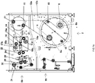
- FIG 1a a device for providing and connecting material webs comprising metal is shown schematically in side view.
- This device has a material web supply device 2, in which according to the in Figure 1a embodiment shown a turntable 4 is rotatably mounted.
- a turntable 4 On the turntable 4, two bearing pins 6 are arranged at a diametrical distance from one another, which are oriented parallel to the axis of rotation of the turntable 4, which is not shown in the figures.
- the bearing pins 6 are used to detachably accommodate reels that are in Figure 1 are identified by the reference symbols "8a" and "8b".
- two diametrically opposite guide rollers 10 are arranged on the turntable 4, the axes of rotation of which are oriented parallel to the axis of rotation of the turntable 4.
- the bobbins 8a and 8b each contain a wound metal strip 12a and 12b, respectively.
- the reels 8a, 8b are to the Bearing pins 6 rotatably mounted in order to be able to pull off the metal strip 12a or 12b.
- the metal strip used preferably has a width of 4 mm and a thickness of approximately 0.05 to 0.06 mm.
- metal-containing material webs can be used, in particular with different widths such as, for example, 2 to 30 mm, 3 to 28 mm, 3.5 to 6.5 mm, 4 to 6 mm , 15 to 25 mm, 15 to 22 mm, 15 to 18 mm or 22 to 25 mm and / or with different thicknesses such as 20 to 500 ⁇ m, 40 to 70 ⁇ m, 80 to 120 ⁇ m or 150 to 250 ⁇ m and / or in In the form of a perforated or net-like or grid-like strip, basically conceivable.
- the bobbin 8a shown on the left is the old bobbin, from which the old metal strip 12a is drawn off (and then slowly running out), and the bobbin 8b shown on the right is the new bobbin that holds the incoming new metal strip 12b provides.
- the turntable 4 undergoes a rotary movement in the view of FIG Figure 1a Subjected counterclockwise, whereby the new reel 8b takes over the position of the old reel 8a and the old reel 8a is moved to the position of the new reel 8b in order to be exchanged there for another new reel, which is then placed on the bearing mandrel 6 will.
- the guide roller 10 located adjacent to the new reel 8b is used to correctly guide the new metal strip 12b for the subsequent process, which is still to be described.
- the new metal strip 12b then disengages from the guide roller 10 and is given the same orientation as the old metal strip 12a before.
- the width of the bobbins 8a, 8b between their flanged disks on both sides is usually a multiple of the width of the wound metal strip, in relation to the direction of movement the Metal strips 12a, 12b downstream two guide rollers 14 movably mounted transversely to the direction of movement of the metal strips 12a, 12b, which take on the task of a centering device in order to then guide the metal strips 12a, 12b in a defined orientation for the further subsequent process.
- a first weakening device 16a for the old metal strip 12a running out and a second weakening device 16b for the incoming new metal strip 12b are provided.
- the first weakening device 16a has an engagement roller 17a and a pressure roller 18a prestressed in the direction of the engagement roller 17a, the old metal strip 12a running off between these two rollers 17a, 18a being guided.
- the second weakening device 16b has an engagement roller 17b and a pressure roller 18b, the incoming new metal strip 12b also being guided between these two rollers 17b, 18b.
- the engagement rollers 17a, 17b of the two weakening devices 16a, 16b are designed, preferably in the manner of an embossing roller, in such a way that they have a weakened point in the respective metal strip 12a, 12b, in particular in the form of a notch oriented at an angle or transverse to the direction of movement of the metal strips 12a, 12b or a knurling or at least one hole or a perforation or an incision or a constriction. Further details with regard to the function of these two attenuation devices 16a, 16b will be explained in more detail at a later point in this description.
- the device has a retensioning winder 20, which is used to separate a remainder of the expiring old metal strip 12a from the process and to wind it up.
- a pair of further guide rollers 22 are provided downstream and a connecting unit 24 is provided downstream of these.
- the guide rollers 22 serve to guide the metal strips 12a, 12b to the connecting unit 24 in a defined orientation.
- connection unit 24 has the task of attaching the incoming new metal strip 12b to the old metal strip 12a that is running out.
- the connection unit 24 is described in more detail below.
- a guide roller 26 is arranged in order to transport the then single metal strip 12 to further processes in subsequent stations (not shown).
- a further guide roller 28 is also arranged downstream of the connecting unit 24 in order to guide a leader to be separated from the incoming new metal strip 12b to a leader winder 30, which is provided to wind up the leader and thus separate it from the process.
- FIG. 1b The design shown differs from the design according to Figure 1a in that the turntable 4 with the guide rollers 10 is not provided, but instead the bearing mandrels 6 are arranged in a stationary manner, so that the exchange of the reels always takes place alternately with regard to the position. Since, in contrast to running Figure 1a with regard to the orientation and the course of the path, a differentiation is no longer made between the old metal strip 12a running out and the new metal strip 12b running in, the embodiment differs from FIG Figure 1b of the execution according to Figure 1a furthermore in that a retension winder 20 and a pre-tension winder 30 and thus a pair of retension winders 20 and a pair of pre-tension winders 30 are provided for each metal strip 12a, 12b. Otherwise, the construction corresponds to the design according to Figure 1b according to the construction of the execution Figure 1a , so that to avoid repetition, refer to the description of the execution of Figure 1a is referred.
- FIG. 1c The design shown differs from the design according to Figure 1a in that downstream of the turntable 4 carrying the reels 8a, 8b, an additional turntable 5 is arranged, which carries two diametrically opposite guide rollers 11, over each of which one of the two metal strips 12a, 12b and is deflected in the direction of the weakening devices 16a, 16b.
- the axes of rotation of the additional turntable 5 and their guide rollers 11 are oriented parallel to the axis of rotation of the turntable 4.
- the metal strips 12a, 12b to form the associated bobbin 8a and 8b are preferably wound in a reciprocally oscillating arrangement similar to a thread spool, they are subjected to an axially oriented reciprocal oscillation when they are unwound.
- This oscillation can be eliminated particularly advantageously along a longer path which is created by the arrangement of the additional turntable 5 in order to transfer the metal strips 12a, 12b into a smooth straight-ahead run before entering the attenuation devices 16a, 16b.
- 1a consists in the fact that the retension winder is omitted and instead a, preferably plate-shaped, magnetic element 21 is arranged between the additional turntable 5 and the weakening devices 16a, 16b, which briefly fixes the leading end of a remaining remainder of the old metal strip 12a running off before the old bobbin 8a is then subjected to an opposite rotation in order to wind up the remainder of the old metal strip 12a, which forms the trailer, and is then removed from the associated bearing mandrel to make room for a new bobbin.
- This measure is of course only suitable for the case that the metal strips 12a, 12b have ferromagnetic material, but this is preferably the case.
- the pretensioning winder 30 can also have magnetic material or a magnetic element in order to fix the leading end of the new metal strip 12b, which forms the pretensioning, in a simple and at the same time particularly effective manner.
- an additional magnetic element 31 is arranged adjacent to the pretension winder 30, to which the leading end of the new metal strip 12b adheres after a rotational movement of the pretension winder 30.
- connection unit 24 has an arrangement of two segments 32, 34 which are spaced apart from one another to form an intermediate space for receiving an arrangement of the superimposed metal strips 12a, 12b to be connected and each have an end face 32a and 34a.
- both segments 32, 34 are mounted rotatably about an axis of rotation 36 and 37, respectively.
- the two axes of rotation 36, 37 are oriented parallel to one another and to a plane spanned by the metal strips 12a, 12b and essentially at right angles to the direction of movement of the metal strips 12a, 12b according to arrow A.
- the segments 32, 34 are each assigned a drive 38 or 39, which sets the associated segment 32 or 34 in a pivoting movement.
- the end faces 32a, 34a of the segments 32, 34 are convexly curved.
- the curved end faces lie at least in sections in a virtual curved plane to which the axes of rotation 36, 37 run parallel.
- the end faces 32a, 34a are each subdivided into a section 32aa or 34aa leading in relation to the direction of movement A of the metal strips 12a, 12b and a trailing section 32ab or 34ab.
- the end face 32a or 34a of the segments 32, 34 is provided with a curvature such that the radius of curvature coincides with the swivel radius between this section 32aa or 34aa of the end face 32a or 34a and the axis of rotation 36 or 37 is defined.
- the trailing section 32ab or 34ab which is also referred to as the run-out area, is also curved on the end faces 32a, 34a of the segments 32, 34, it has such a convex curvature that the radius of curvature is greater is than the aforementioned swing radius.
- the trailing section 32ab or 34ab of the end faces 32a, 34a of the segments 32, 34 takes on the task of a clamping engagement section, whereby the arrangement of the metal strips 12a, 12b to be connected for one double-sided clamping engagement by the segments 32, 34 is subjected.
- the slight curvature ensures that the distance between the opposing end faces 32a, 34a of the segments 32, 34 in the area of the trailing sections 32ab, 34ab is reduced to an amount that is slightly less than the thickness of the arrangement of the metal strips 12a to be connected , 12b is. Further details in connection with the function of these trailing sections 32ab, 34ab of the end face 32a, 34a of the segments 32, 34 are explained in more detail below at a later point.
- each segment 32, 34 contains a welding electrode 40 or 41, one of these welding electrodes 40, 41 forming the anode and the other of these welding electrodes 40, 41 forming the cathode.
- the welding electrodes 40, 41 are arranged in a recess within the segments 32, 34 and have an electrode tip 40a or 41a, which is led to the end face 32a or 34a of the respective segment 32 or 34 and there with its end exposed. If necessary, the end of the electrode tip 40a or 41a can also protrude slightly from the end face 32a or 34a of the segments 32, 34 in the manner of a projection.
- the electrode tips 40a, 41a lie approximately in the middle between the leading section 32aa or 34aa and the trailing section 32ab and 34ab of the end faces 32a, 34a of the segments 32, 34.
- leading section 32aa or 34aa and the trailing section 32ab or 34ab of the end faces 32a, 34a can alternatively be designed as essentially flat surfaces and angled to one another in such a way that the distance between the end faces 32a, 34a of the respective axis of rotation 36 or 37 of the segments 32, 34 is greatest in the area of the electrode tip 40a or 41a and with increasing distance from the electrode tip 40a or 41a along the leading section 32aa or 34aa and the trailing section 32ab or .34ab reduced.
- the welding electrodes 40, 41 are attached to the segments 32, 34 with a clamp bracket 42, which can be released in order to be able to adjust the welding electrodes 40, 41 with respect to the segments 32, 34 and in particular in their height with respect to their end faces 32a and 34a and thus be able to adjust them accordingly.
- a threaded bolt can also be used as the electrode adjustment device, which is coupled to the welding electrodes 40, 41 in such a way that a rotation of this threaded bolt effects an adjustment of the welding electrode in their longitudinal direction.
- the welding electrodes 40, 41 are supplied via cables (not shown) that are connected to a stationary external electrical power supply device which, together with the welding electrodes 40, 41, is part of an electric welding device, but is not fully shown in the figures.
- the electric welding device has at least one capacitor, which is also not shown in the figures.
- Such a capacitor can advantageously be used as a store of large electrical energy, which can be delivered within a very short time to supply the welding electrodes 40, 41, while, on the other hand, no high demands have to be made on the electrical energy supply device, since significantly more time is required for the charging process Available; because the time intervals between reel changes are relatively long.
- the capacitor is preferably arranged in a stationary manner and the electrical energy to be discharged from the capacitor is transmitted to the welding electrodes 40, 41 via the cables already mentioned.
- the drives 38, 39 and the welding electrodes 40, 41 are controlled via a control device which is also not shown in the figures.
- the drives 38, 39 and the control device are designed in such a way that the segments 32, 34 accelerate synchronously from an initial rest position upstream in relation to the direction of movement of the metal strips 12a, 12b according to arrow A to a working position, from the working position to a related position on the direction of movement of the metal strips 12a, 12b downstream end rest position is braked and then an opposite movement from the end rest position to the initial rest position is interrupted.
- the angular distance between the initial rest position and the final rest position is approximately 270 °.
- the welding electrodes 40, 41 are permanently connected to the capacitor mentioned and are therefore permanently under voltage. Care must be taken that this voltage has a value that enables the formation of a Spark or arc between the electrode tips 40a, 41a of the two welding electrodes 40, 41 is automatically caused when a predetermined minimum distance between the two electrode tips 40a, 41a is not reached, which is the case when the segments 32, 34 enter the working position. Accordingly, the welding electrodes 40, 41 can be permanently active.
- the mentioned control device As an alternative to permanent activation of the welding electrodes 40, 41, it is also conceivable to also design the mentioned control device to control the welding electrodes 40, 41 in such a way that in the working position of the segments 32, 34 the control device releases an at least partial discharge of the aforementioned capacitor.
- the control device should control the welding electrodes 40, 41 in such a way that they are activated exactly when the segments 32, 34 enter the working position and are deactivated again when the working position is left.
- the welding process takes place as spot welding. This is completely sufficient for the connection of the relatively thin and narrow metal strips 12a, 12b to one another, especially since relatively little electrical energy is required and only a spatially very limited heat generation is to be expected, since the welding process only takes place within a very short period of time, which is preferably not takes longer than a second. In any case, the welding time is so short that the pivoting movement of the segments 32, 34 does not need to be interrupted, but rather the segments 32, 34 can move on in synchronism with the metal strips 12a, 12b. Since the segments 32, 34 continue to move during the welding process, the working position is thus to be defined over a certain, albeit small, angular range and can therefore alternatively be referred to as the working range.
- the new metal strip 12b is provided with a weakened point 46, which is specifically formed in its initial section. Furthermore, with regard to the direction of movement of the metal strips 12a, 12b, the old metal strip 12a is also provided with a weakened point 48 which, with regard to the direction of movement of the metal strips 12a, 12b, is at a distance upstream from the weakened point 46 formed in the new metal strip 12b located. How in particular Figure 2c can be seen, the offset positioning of these two weakened points 46, 48 in relation to the connection point 44 is to be coordinated such that the connection point 44 is formed between the two weakened points 46, 48.
- the distance between the weakened point 46 formed in the starting section 12ba of the incoming new metal strip 12b and the connection point 44 created by the welding electrodes 40, 41 between the metal strips 12a, 12b should preferably be less than the distance between the connection point 44 and the end section 12aa of the outgoing metal strip old material web 12a produced weakened point 48, such as in particular Figure 2c clearly shows.
- the formation of the weakened points 46, 48 serve to weaken the metal strips 12a, 12b accordingly, in order to cause a separation there by tearing off.
- the pre-tensioning winder 30 ( Figure 1 ) set to an overspeed in order to act on the leading starting section 12ba of the new metal strip 12b at a slightly higher speed than the normal speed of movement of the metal strips 12a, 12b, which corresponds to the process speed and can also be referred to as the nominal speed, which leads to a tear leads at the weakened point 46.
- the post-tension winder 20 and the pre-tension winder 30 are also controlled accordingly by the control device.
- the trailing sections 32ab, 34ab of the end faces 32a, 34a also play an important role, as they hold the two metal strips 12a, 12b in the area of their still overlapping arrangement immediately upstream behind the connection point 44 as clamping engagement sections. This ensures that the tensile force generated during the separation process is, so to speak, absorbed by the segments 32, 34 at their end faces 32a, 34a and thus any damage to the metal strips 12a, 12b is prevented.
- the weakening devices 16a, 16b are provided to form the aforementioned weakened points 46, 48, which can alternatively also be referred to as weakenings Figure 1 have been described.
- the weakening devices 16a, 16b are designed according to FIG Figure 1 to be controlled accordingly by the control device and, if necessary, also to be arranged spatially offset from one another.
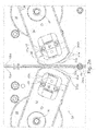
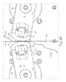
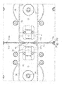
- the weakening device is in the form of a projection designed first weakening element 50, which with respect to the direction of movement A of the metal strips 12a, 12b downstream after the electrode tip 41a on the end face 34a of the second segment 34 and to generate the weakened point 46 in the Starting portion 12ba of the incoming new metal strip 12b is provided, as in particular Figure 3d can be seen, and also implemented in the form of a second weakening element 52 designed as a projection, which is arranged in relation to the direction of movement A of the metal strips 12a, 12b upstream in front of the electrode tip 40a on the end face 32a of the first segment 32 and to generate the weakened point 48 is provided in the end portion 12aa of the expiring old metal strip 12a, such as in particular Figure 3f combined with Figure 3e reveals.
- the weakening elements 50, 52 can in principle extend over the entire width of the metal strip 12a, 12b. Alternatively, it is also conceivable to design the weakening elements 50, 52 in such a way that they do not weaken the metal strip 12a, 12b over its entire width, but only in a certain section, in certain areas or at certain points and on the other hand in the other areas leave the metal strips 12a, 12b untouched and thus not achieve any weakening there. For example, with a width of the metal strip 12a, 12b of 4 mm, two, three, four, five or six, preferably equidistant from one another, webs arranged over the width of the metal strip 12a, 12b each with a width of 0.3 mm, for example, can be produced.
- the cross-sectional shape shown schematically can alternatively also be designed as a pointed cutting edge or with a pointed cutting edge, as a result of which the weakening effect can be reinforced or an essentially complete severing of the respective metal strip 12a or 12b can be achieved.
- the oscillating movement acting in the transverse direction, to which the metal strip 12a or 12b is subjected when being pulled from the respective reel 8a or 8b, can thereby be eliminated particularly effectively, so that after passing a first spherical roller such as the guide rollers 10 and / or the downstream guide rollers 14 in the first embodiment of the device shown in FIG. 1 a or the guide rollers 14 in the FIG Figure 1b
- the illustrated second embodiment of the device of the metal strips 12a or 12b is brought into a smooth straight line and thus then runs without disruptive transverse movements.
- the curvature causes the opposing metal strips 12a, 12b at their highest point (viewed radially) and thus essentially in the middle.
- the welding point is also created in a defined manner in the middle of the two metal strips 12a, 12b, since, as mentioned, the two opposing metal strips 12a, 12b touch each other first.
- the metal strips 12 or 12a, 12b are guided over several guide rollers 10, 14, 22, 26, 28.
- the web tension i.e. the tension in the metal strip
- the metal strip is cut off on one side of a guide roller and pulled on the other side of this roller.
- this is the case in particular when connecting the two metal strips 12a, 12b.
- one solution would be to provide a guide, a holder, a sheet metal or a protective element adjacent to the circumference of the roller, but this would have the disadvantage that the metal strip would be much more difficult to thread over the roller can be.
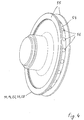
- the in Figure 4 illustrated preferred embodiment is an alternative solution in one or more of the in the device according to Figure 1 used guide rollers 10, 14, 22, 26 and / or 28 along the circumference 54, which is delimited by two lateral flange-like edges 55, to provide magnetic elements 56, which are arranged so that their outside is essentially flush with the circumference 54 and thus is arranged in alignment with the circumference 54.
- the magnet elements 56 are arranged substantially equidistant from one another over the circumference 54; alternatively, however, it is also conceivable to provide the roller along its circumference 54 instead of discrete magnetic elements 56 completely with magnetic material, for example in the form of a magnetic strip or by coating with magnetic material.
- FIG Figure 1 downstream of the guide roller 26, which in turn is downstream of the connecting unit 24, a dancer arrangement 60 is provided, which in FIG Figure 5 is shown enlarged in a preferred embodiment in detail.
- the dancer arrangement 60 shown by way of example has a guide roller 62 which, like the guide rollers 10, 14, 22, 26 and 28, is designed as a single disk or single track.
- the dancer arrangement 60 also has two further groups of coaxially arranged, single-track rollers 64 and 66 each. Each group of rollers 64, 66 forms, depending on the number of rollers, a corresponding multi-lane roller arrangement, in contrast to the guide roller 62, which is only a single-lane roller.
- the two groups of rollers 64 and 66 each have four rollers and thus form a four-track roller arrangement.
- a correspondingly multi-lane roller instead of single-lane rollers that are combined to form a multi-lane group and are arranged coaxially to one another.
- the metal strip 12 is guided between the two groups of rollers 64 and 66 in the manner of a pulley system, wherein in the in Figure 5 illustrated embodiment, a block and tackle is formed with eight times the reduction. So that the individual runs of the metal strip 12 between the two groups of rollers 64 and 66 do not collide with one another, the two groups of rollers 64 and 66 are arranged offset from one another by half a web width.
- While one group of rollers 64 is arranged in a stationary manner, the other group of rollers 66 is mounted on the free end 68a of a movable dancer arm 68.
- the other end 68b of the dancer arm 68 is non-rotatably mounted on an output shaft 70a of an electric motor 70, so that the dancer arm 68 extends in the radial direction with respect to the output shaft 70a of the electric motor 70.
- the dancer arm 68 With the help of the electric motor 70, the dancer arm 68 thus becomes a Subjected pivoting movement, the pivoting movement being carried out in such a way that the metal strip 12 is tensioned with its strand between the two groups of rollers 64 and 66, as Figure 5 can be seen schematically.
- the pivot position of the dancer arm 68 is monitored by sensors, which in the illustrated embodiment are according to FIG Figure 5 it is a question of non-contact sensors 72, which are designed, for example, as proximity switches. Depending on the measurement signals from the sensors 72, the electric motor 70 is controlled accordingly via a control device (not shown).
- a dancer arrangement is known in principle and is used primarily to control the web tension.
- the advantage of the dancer arrangement 60 described consists in its additional function as a memory, since a relatively long section of the metal strip 12 and thus a relatively large amount of material can be stored in a relatively small space due to the previously described pulley arrangement.
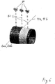
- the metal strip 12a or 12b is wound on the associated bobbin core 8aa or 8bb due to its small width, preferably in a reciprocally oscillating arrangement similar to that of a thread spool Figure 6 can be seen schematically.
- the speed of the withdrawn web material and the speed of the reel running off are used to determine the correct time
- the diameter of this reel is calculated relatively precisely, as there is no marking on the web material shortly before the end that could be optically recognized.
- the in Figure 6 However, such a calculation inevitably means that a relatively large proportion of the metal strip 12a or 12b is still on the bobbin core 8aa or 8bb before the end of the metal strip 12a or 12b is reached.
- the illustrated embodiment uses a plurality of sensors 80 which, with the aid of measuring beams 82, measure the bobbin core 8aa or 8bb or the remaining length of the metal strip 12a or 12b still on the bobbin core 8aa or 8bb. From the measurement signals of these sensors 80 it can then be determined whether there is still a remaining length of the metal strip 12a or 12b on the bobbin core 8aa or 8bb with a lot of looping, in order to determine the exact time to change the bobbin and thus the change of the bobbin then to be initiated on time.
- the sensors 80 are preferably optical sensors which, for example, form several light barriers according to their number.
- a camera system can also be used which looks at the surface of the bobbin or of the associated bobbin core 8aa or 8bb and thereby in particular detects the already visible portion of the bobbin core 8aa or 8bb.
- the bobbin cores 8aa, 8bb should differ in color or in some other way from the metal strips 12a, 12b used.
- a web cutting device can preferably be used which automatically cuts through the metal strip 12 when the web tension is exceeded, for example as a result of a malfunction.
- FIG Figure 7 Such a web cutting device according to a preferred embodiment is shown in FIG Figure 7 shown and marked with the reference symbol "90" and can preferably be used downstream of the dancer arrangement 60, as exemplified in FIG Figure 1c is shown.
- the web cutting device 90 shown as an example has a cutting arrangement 92 which has a stationary outer ring 93 and an inner disk 94 which is rotatably mounted within the outer ring 93.
- the outer ring 93 contains, in its two diametrically opposite sections, in each case a slot 93a running diametrically with respect to the axis of rotation of the inner disk 94.
- the inner disk 94 also contains a slot 94a running diametrically with respect to its axis of rotation, wherein in the in FIG Figure 7a Rotational position of the inner disk 94 shown, the slot 94a of which is aligned with the two slots 93a in the outer ring 93.
- the outer ring 93 can also have a different external shape, provided the other structural features described above are met.
- a lever 96 is non-rotatably arranged on the rotatably mounted inner disc 94, the pivoting movement of which thus triggers a rotary movement of the inner disc 94, as is shown in a comparison of FIG Figure 7b With Figure 7a reveals. Accordingly, the lever 96 can be pivoted about the same axis of rotation as the inner disk 94. At the outer end of the lever 96, a guide roller 98 is rotatably mounted.
- the web cutting device 90 has a magnet holder 100, to which a magnet element 102 is attached in order to move the lever 96 in the Figure 7 position shown.
- the lever 96 must of course be provided with ferromagnetic or magnetizable material at least at the point in engagement with the magnetic element 102.
- the web cutting device 90 according to FIG Figure 7 an input-side guide roller 104, the guide rollers 98 and 104 being arranged so that in the in Figure 7a The position shown of the lever 96 of the metal strip 12 extends through the slots 93a and 94a which are aligned with one another in this position. Furthermore, the web cutting device 90 in the in Figure 7 The embodiment shown also has an output-side guide roller 106, which guides and deflects the metal strip 12, coming from the guide roller 98 on the lever 96, in order to transport it to further processes in subsequent stations (not shown).
- a twist or rotation of the inner disk 94 opposite the outer ring 93 leads to a corresponding movement of the movable cutting edge 94aa formed on the outside of the inner disk 94 with respect to a stationary cutting edge 93aa formed adjacent on the inside of the stationary ring 94, whereby a cutting process is triggered which the metal strip 12 severed.
- the magnetic force of the magnetic element 102 fastened to the magnet holder 100 is dimensioned as a function of a predetermined critical value for the web tension in the metal strip 12. If the web tension in the metal strip 12 exceeds the aforementioned predetermined critical value, the magnetic force generated by the magnetic element 102 is no longer sufficient, so that the lever 96 then moves from the magnetic element 102 on the magnet holder 100 through the strand of the metal strip 12 running from the guide roller 98 to the output-side guide roller 106 pulled away, thus deflected and in the perspective of Figure 7 is abruptly hit down.
- the lever 96 preferably manually, is back in its in Figure 7a The position shown is moved back until the magnetic force of attraction of the magnetic element 102 acts, and the metal strip 12 is then threaded through the now aligned slots 93a, 94a in the outer ring 93 and in the inner disk 94.
- the illustrated preferred embodiment of a web cutting device 90 is a so-called cutting knife-free and intrinsically safe device which makes an additional knife protection, which would make it difficult to thread the metal strip 12, unnecessary.
- FIG 8 shows a schematic side view of an auxiliary tool 110 for threading a new metal strip in longitudinal section according to a preferred embodiment.
- the illustrated auxiliary tool 110 has an elongated tubular shaft 112, at the first end 112a of which a handle 113 protruding at an angle to the longitudinal extension of the shaft 112 is arranged.
- the depicted auxiliary tool 110 has the shape of a pistol.
- the second end 112b of the shaft 112 is provided with a surface which is inclined with respect to the longitudinal extension of the shaft 112 and which is a first clamping surface 112c.
- a clamping element 114 is provided which is provided with a surface which is inclined with respect to the longitudinal extension of the shaft 112 and which is a second clamping surface 114c.
- the clamping member 114 is coupled to a rod 116 which extends through an elongated cavity 112d formed in the shaft 112, such as Figure 8 reveals.
- This rod 116 is movably mounted in the longitudinal direction of the shaft, whereby the clamping element 114 is also arranged movably accordingly.
- the first clamping surface 112c and the second clamping surface 114c are aligned parallel to one another in such a way and the arrangement of the second end 112b of the shaft 112 and the movable clamping element 114 is made such that in the FIG Figure 8 The position shown of the movable clamping element 114, the second clamping surface 114c of which rests on the first clamping surface 112c at the second end 112b of the shaft 112.
- the second end 112b of the shaft 112 can also be referred to as a fixed first clamping piece and the movable clamping element 114 as a movable second clamping piece.
- the movement of the rod 116 and thus of the movable clamping element 114 takes place manually in the illustrated embodiment with the aid of an operating element 118 which is attached to the other end of the rod 116 and protrudes outward through a slot 112e formed in the shaft 112 adjacent to the handle 113.
- the auxiliary tool 110 can thus be held by the hand of a user on the handle 113 and at the same time the operating element 118 can be operated with a finger in a manner similar to the trigger on a pistol.
- auxiliary tool 110 is opened with the aid of the operating element 118, a second hand on the part of the operator not being required to open the auxiliary tool 110.
- a spring 120 is arranged between the operating element 118 and the end of the elongated cavity 112d located adjacent to the handle 113, which the rod 116 and thus the movable clamping element 114 in the Figure 8 pretensioned clamping position shown.
- the operating element 118 only has to be pulled against the pressure of the spring 120 to open the clamping surfaces 112c and 114c against the pressure of the spring 120, while to move the rod 116 and thus the movable clamping element 114 into the in Figure 8
- the operating element 118 shown in the clamping position can simply be released, so that the rod 116 with the movable clamping element 114 then returns to the position shown in FIG Figure 8
- the clamping position shown is spent.
- the device shown is at its (the viewer of Figure 1 facing) front with a so-called protection, which prevents unintentional contact of the units and components by an operator.
- the protection consists of transparent material or at least contains windows made of transparent material such as glass or acrylic, in order to make the units and components of the device visible to the operator.
- This pollution is in Figure 1 not shown, but in Figure 8 in an opposite Figure 1 90 ° rotated view schematically in cross section and identified by the reference number "122".
- an opening 124 in the form of an opening in the direction of the viewer Figure 8 and thus across the plane of Figure 8 extending elongated slot formed.
- the auxiliary tool 110 is inserted with its shaft 112 through this opening 124 in the protection 122 from the outside into the device and can be moved in different directions due to the slot-like shape of the opening 124.
- the operator can then, in the course of a reel change, for example from the reel 8a to the (new) reel 8b according to FIG Figure 1 Grip the new metal strip, for example the metal strip 12b from the (new) bobbin 8b, with the aid of the auxiliary tool 110 and thread it accordingly into the device via the guide rollers 14.
- At least one of the two clamping surfaces 112c, 114c can be provided with a friction coating, as a result of which a possible slipping of the metal strip 12a or 12b is made difficult or even prevented.
- a friction coating can have, for example, ceramic material or tungsten carbide; in principle, however, other materials that cause increased friction are also conceivable.
- the reels 8a, 8b are not only rotatably mounted on the bearing mandrels 6, but can also be set in rotation by a drive (not shown). So that the metal strip 12a or 12b can be threaded in comfortably with the auxiliary tool 110 described above, the drive of the new reel 8a or 8b is switched on to provide traction support.
- the advantage of this measure is that the threading process is comfortably supported by switching on the drive of the new bobbin and the pulling support does not have to be additionally activated manually while the auxiliary tool 110 is being handled, but is automatically activated during threading operation with the guard 122 closed. As soon as the threading process has been completed and the handling of the auxiliary tool 110 has ended, the traction assistance is switched off again.
- the sensors mentioned can be designed as inductive proximity switches, for example, which detect markings provided on the associated roller, for example in the form of holes, in order to determine in this way that the associated roller has been set in rotation by the threading process. Alternatively, however, it is also conceivable, for example, to provide the sensors as rotary encoder for detecting a rotation of the associated roller.
Landscapes
- Engineering & Computer Science (AREA)
- Mechanical Engineering (AREA)
- Physics & Mathematics (AREA)
- Optics & Photonics (AREA)
- Replacement Of Web Rolls (AREA)
- Wire Processing (AREA)
- Fixed Capacitors And Capacitor Manufacturing Machines (AREA)
- Machines For Laying And Maintaining Railways (AREA)
Claims (17)
- Dispositif pour l'industrie de transformation du tabac, permettant de relier une bande de matériau (12a) sortante présentant du métal à une nouvelle bande de matériau entrante présentant du métal, comprenant- un agencement (24) constitué de deux segments (32, 34) qui sont espacés l'un de l'autre avec formation d'un espace intermédiaire permettant d'accueillir un agencement de bandes de matériau (12a, 12b) superposées devant être reliées qui comprennent une bande de matériau (12a) sortante présentant du métal et une nouvelle bande de matériau (12b) entrante présentant du métal et présentent respectivement une surface frontale (32a, 34a), au moins un des segments (32, 34) étant monté de manière mobile et pouvant être amené dans une position de travail au sein de laquelle sa surface frontale (32a) fait face à la surface frontale (34a) de l'autre segment (34) à une distance minimale incluant l'agencement des bandes de matériau (12a, 12b) devant être reliées,- un dispositif d'entraînement (38, 39) permettant de déplacer ledit au moins un segment (32, 34),- un dispositif de soudage électrique avec un premier agencement d'électrodes (40) présentant une polarité et un second agencement d'électrodes (41) présentant l'autre polarité, la surface frontale (32a) d'un segment (32) étant munie d'au moins une section (40a) du premier agencement d'électrodes (40) et la surface frontale (34a) de l'autre segment (34) étant munie d'au moins une section (41a) du second agencement d'électrodes (41), et le dispositif de soudage électrique étant conçu pour effectuer une opération de soudage dans la position de travail des segments (32, 34) afin de relier les bandes de matériau (12a, 12b), et- un dispositif de commande conçu pour commander le dispositif d'entraînement (38, 39) de telle manière que ledit au moins un segment (32, 34) monté de manière mobile soit amené dans la position de travail et soit ensuite éloigné de la position de travail,- caractérisé en ce que le dispositif de commande est conçu pour adapter ledit au moins un segment (32, 34) monté de manière mobile avec sa surface frontale (32a, 34a) à un mouvement de l'agencement des bandes de matériau (12a, 12b) devant être reliées de telle manière que, dans la position de travail, ledit au moins un segment (32, 34) monté de manière mobile avec sa surface frontale (32a, 34a) soit déplacée à une vitesse approximativement synchrone et de manière approximativement parallèle à l'agencement des bandes de matériau (12a, 12b) devant être reliées.
- Dispositif selon la revendication 1,
dans lequel au moins un segment (32, 34) présente un dispositif de réglage d'électrode (42) qui est conçu pour régler l'agencement d'électrodes (40, 41) dans l'espace par rapport à la surface frontale (32a, 34a) et en particulier dans sa hauteur par rapport à la surface frontale (32a, 34a). - Dispositif selon au moins une des revendications précédentes,
dans lequel le dispositif de commande est en outre conçu pour commander le dispositif de soudage électrique de telle manière que, dans la position de travail, le dispositif de soudage électrique soit activé pendant un intervalle de temps déterminé. - Dispositif selon au moins une des revendications précédentes,
dans lequel l'agencement (24) des deux segments (32, 34) est constitué de telle manière que, dans la position de travail, la surface frontale (32a) d'un segment (32) puisse être amenée au moins en contact avec un côté de l'agencement des bandes de matériau (12a, 12b) devant être reliées et la surface frontale (34a) de l'autre segment (34) puisse être amenée au moins en contact avec l'autre côté, faisant face, de l'agencement des bandes de matériau (12a, 12b) devant être reliées. - Dispositif selon au moins une des revendications précédentes,
dans lequel le dispositif d'entraînement (38, 39) et le dispositif de commande permettant de commander le dispositif d'entraînement (38, 39) sont conçus de telle manière que ledit au moins un segment monté de manière mobile soit accélé entre une position de repos initiale et la position de travail, soit freiné entre la position de travail et une position de repos finale et soit ensuite soumis à un mouvement opposé entre la position de repos finale et la position de repos initiale, la position de travail se trouvant de manière préférée approximativement au milieu du trajet de déplacement entre la position de repos initiale et la position de repos finale. - Dispositif selon au moins une des revendications précédentes,
dans lequel ledit au moins un segment (32, 34) monté de manière mobile est monté de manière à pouvoir pivoter autour d'un axe de rotation (36, 37) qui est orienté de manière essentiellement parallèle à un plan défini par l'agencement des bandes de matériau (12a, 12b) devant être reliées et de manière essentiellement perpendiculaire par rapport à la direction de déplacement de l'agencement des bandes de matériau (12a, 12b) devant être reliées. - Dispositif selon la revendication 6,
dans lequel la surface frontale (32a, 34a) du segment est incurvée de manière convexe, au moins une section (32aa, 34aa) de la surface frontale (32a, 34a) présentant une courbure telle que le rayon de courbure coïncide essentiellement avec le rayon de pivotement défini entre la surface frontale (32a, 34a) et l'axe de rotation (36, 37). - Dispositif selon au moins une des revendications précédentes,
dans lequel la surface frontale (32a, 34a) d'au moins un segment (32, 34) est munie d'une section de mise en prise par serrage (32ab, 34ab) conçue pour mettre en prise par serrage l'agencement des bandes de matériau (12a, 12b) devant être reliées et est prévue de manière préférée au niveau de la surface frontale (32a, 34a) du segment (32, 34) en aval de l'agencement d'électrodes (40, 41) par rapport à la direction de déplacement de l'agencement des bandes de matériau (12a, 12b) devant être reliées. - Dispositif selon les revendications 7 et 8,
dans lequel la partie de mise en prise par serrage (32ab, 34ab) est incurvée de manière convexe, le rayon de courbure étant supérieur au rayon de pivotement. - Dispositif selon au moins une des revendications précédentes,
dans lequel les deux segments (32, 34) sont montés de manière mobile. - Dispositif selon au moins une des revendications précédentes,
comprenant un dispositif d'affaiblissement (16a, 16b ; 50, 52) qui est conçu pour produire, dans la section initiale (12ba) de la nouvelle bande de matériau (12b) entrante et, en amont de celle-ci, dans la section finale (12aa) de la bande de matériau (12a) sortante, respectivement un point d'affaiblissement (46, 48), en particulier sous la forme d'une entaille orientée de manière angulaire ou transversale par rapport à la direction de déplacement des bandes de matériau (12a, 12b) ou d'un moletage ou d'au moins un trou ou d'une perforation ou d'une incision ou d'une gorge. - Dispositif selon la revendication 11,
dans lequel le dispositif d'affaiblissement (16a, 16b) est prévu en amont de l'agencement des segments par rapport à la direction de déplacement des bandes de matériau. - Dispositif selon la revendication 11,
dans lequel le dispositif d'affaiblissement (50, 52) comprend un premier élément d'affaiblissement (50), de manière préférée réalisé sous forme de saillie, qui est agencé au niveau de la surface frontale (34a) d'un segment (34) en aval de l'agencement d'électrodes (40, 41) par rapport à la direction de déplacement (A) des bandes de matériau (12a, 12b) et qui est prévu afin de produire un point d'affaiblissement (46) dans la section initiale (12ba) de la nouvelle bande de matériau (12b) entrante, et un second élément d'affaiblissement (52), de manière préférée réalisé sous forme de saillie, qui est agencé au niveau de la surface frontale (32a) de l'autre segment (32) en amont de l'agencement d'électrodes (40, 41) par rapport à la direction de déplacement (A) des bandes de matériau (12a, 12b) et qui est prévu afin de produire un point d'affaiblissement (48) dans la section finale (12aa) de la bande de matériau (12a) sortante. - Dispositif selon au moins une des revendications précédentes,
comprenant un premier dispositif de rejet (30) qui est prévu en aval de l'agencement (24) des segments (32, 34) par rapport à la direction de déplacement (A) des bandes de matériau (12a, 12b) et est conçu pour rejeter la section initiale (12ba) de tête de la nouvelle bande de matériau (12b) entrante, et un second dispositif de rejet (20) qui est prévu en amont de l'agencement (24) des segments (32, 34) par rapport à la direction de déplacement (A) des bandes de matériau (12a, 12b) et est conçu pour rejeter la section finale (12aa) de queue de la bande de matériau (12a) sortante, le dispositif de commande étant conçu pour commander les deux dispositifs de rejet (20, 30) de telle manière que la section initiale (12ba) de tête de la nouvelle bande de matériau (12b) entrante soit transportée au moins temporairement dans le premier dispositif de rejet (30) à une vitesse de déplacement qui est supérieure à la vitesse de déplacement des bandes de matériau (12a, 12b) dans la région de la position de travail des segments (32, 34), et la section finale (12aa) de queue de la bande de matériau (12a) entrante soit transportée dans le second dispositif de rejet (20) à une vitesse de déplacement inférieure à la vitesse de déplacement des bandes de matériau (12a) dans la région de la position de travail des segments, - Dispositif selon au moins une des revendications précédentes, comprenant un agencement compensateur (60),
caractérisé en ce que l'agencement compensateur (60) comprend un agencement de rouleaux à bandes multiples stationnaire (64) et un agencement de rouleaux à bandes multiples mobile (66), les deux agencements de rouleaux (64, 66) sont agencés de manière décalée l'un par rapport à l'autre d'une demi-largeur de bande, et la bande de matériau (12) est guidée entre les deux agencements de rouleaux (64, 66) à la manière d'un palan. - Dispositif selon au moins une des revendications précédentes, caractérisé par un dispositif de séparation de bande (90) qui comprend des moyens de coupe (93, 94) permettant de sectionner la bande de matériau (12) et un levier (96) monté pivotant et placé en aval dans la direction de convoyage de la bande de matériau (12) et au niveau de l'extrémité libre duquel est prévu un élément de guidage, de manière préférée un rouleau, (98) permettant de guider la bande de matériau (12), les moyens de coupe (93, 94) étant couplés au levier (96) de sorte que les moyens de coupe (93, 94) permettant de sectionner la bande de matériau (12) soient activés grâce à un mouvement de pivotement du levier (96).
- Dispositif comprenant un premier dispositif selon au moins une des revendications précédentes et un second dispositif prévu en aval par rapport à la direction de déplacement des bandes de matériau qui est conçu pour relier une extrémité (12bb) de tête, formée après séparation d'une section initiale de tête, de la nouvelle bande de matériau (12b) entrante à la bande de matériau (12a) sortante, et qui est conçu du reste selon au moins une des revendications précédentes.
Priority Applications (1)
| Application Number | Priority Date | Filing Date | Title |
|---|---|---|---|
| PL18186273T PL3434406T3 (pl) | 2017-07-28 | 2018-07-30 | Urządzenie do łączenia wstęg materiału |
Applications Claiming Priority (1)
| Application Number | Priority Date | Filing Date | Title |
|---|---|---|---|
| DE102017117145.2A DE102017117145A1 (de) | 2017-07-28 | 2017-07-28 | Vorrichtung zum Verbinden von Materialbahnen |
Publications (2)
| Publication Number | Publication Date |
|---|---|
| EP3434406A1 EP3434406A1 (fr) | 2019-01-30 |
| EP3434406B1 true EP3434406B1 (fr) | 2021-12-22 |
Family
ID=63144814
Family Applications (1)
| Application Number | Title | Priority Date | Filing Date |
|---|---|---|---|
| EP18186273.1A Active EP3434406B1 (fr) | 2017-07-28 | 2018-07-30 | Dispositif de raccordement de bandes de matière |
Country Status (4)
| Country | Link |
|---|---|
| EP (1) | EP3434406B1 (fr) |
| CN (1) | CN109304537B (fr) |
| DE (1) | DE102017117145A1 (fr) |
| PL (1) | PL3434406T3 (fr) |
Cited By (1)
| Publication number | Priority date | Publication date | Assignee | Title |
|---|---|---|---|---|
| EP4302985A1 (fr) | 2022-06-28 | 2024-01-10 | Körber Technologies GmbH | Dispositif et procédé de fabrication de tubes creux |
Families Citing this family (2)
| Publication number | Priority date | Publication date | Assignee | Title |
|---|---|---|---|---|
| PL242542B1 (pl) * | 2020-12-23 | 2023-03-13 | Politechnika Poznanska | Zespół prowadzenia i odbioru pasa, zautomatyzowanego urządzenia do zgrzewania doczołowego pasów cięgnowych |
| DE102023107801A1 (de) * | 2023-03-28 | 2024-10-02 | Körber Technologies Gmbh | Vorrichtung und Verfahren zum Verbinden von zwei jeweils von einer Bobine ablaufenden, Metall aufweisenden Materialbahnen endlicher Länge zu einer für eine unterbrechungsfreie Produktion verwendbaren, endlosen Materialbahn |
Citations (6)
| Publication number | Priority date | Publication date | Assignee | Title |
|---|---|---|---|---|
| DE3345452A1 (de) | 1983-12-15 | 1985-06-27 | Hermann Schleicher Gmbh & Co Maschinenfabrik, 8520 Erlangen | Schneid- und schweissvorrichtung fuer das beschneiden und schweissen von enden von blechbaendern |
| JPS6238778A (ja) | 1985-08-14 | 1987-02-19 | Teikoku Denki Kk | 金属帯状のウエブの点溶接装置 |
| DE29510277U1 (de) | 1995-06-24 | 1995-09-14 | Wintzer, Harald, 75180 Pforzheim | Vorrichtung, insbesondere für das Schweißen von endlos aneinanderzufügenden Bändern |
| EP1108492A2 (fr) | 1999-12-17 | 2001-06-20 | Sundwig GmbH | Procédé et dispositif pour le soudage bout à bout des extrémités de bandes métalliques par soudage par résistance |
| US20040238495A1 (en) | 2003-05-30 | 2004-12-02 | Byerly Steven M. | Apparatus and method for supplying a continuous source of wire |
| US20060070984A1 (en) | 2004-09-30 | 2006-04-06 | Lincoln Global, Inc. | Feeder for endless welding wire |
Family Cites Families (5)
| Publication number | Priority date | Publication date | Assignee | Title |
|---|---|---|---|---|
| FR2656246B1 (fr) * | 1989-12-22 | 1992-04-30 | Europ Propulsion | Procede de soudage electrique par points d'elements filtrants metalliques. |
| USRE36612E (en) * | 1995-02-23 | 2000-03-14 | Toyota Jidosha Kabushiki Kaisha | Mash seam welding process and mash seam welding apparatus |
| AT413504B (de) * | 2002-07-03 | 2006-03-15 | Fronius Int Gmbh | Elektrodenschutzeinrichtung |
| AT503193B1 (de) * | 2006-02-08 | 2007-10-15 | Fronius Int Gmbh | Band zum schutz der elektroden einer punktschweisszange |
| JP5165335B2 (ja) * | 2007-10-20 | 2013-03-21 | スチールプランテック株式会社 | 圧延設備用溶接機、圧延設備および圧延方法 |
-
2017
- 2017-07-28 DE DE102017117145.2A patent/DE102017117145A1/de not_active Withdrawn
-
2018
- 2018-07-30 CN CN201810859456.1A patent/CN109304537B/zh active Active
- 2018-07-30 EP EP18186273.1A patent/EP3434406B1/fr active Active
- 2018-07-30 PL PL18186273T patent/PL3434406T3/pl unknown
Patent Citations (6)
| Publication number | Priority date | Publication date | Assignee | Title |
|---|---|---|---|---|
| DE3345452A1 (de) | 1983-12-15 | 1985-06-27 | Hermann Schleicher Gmbh & Co Maschinenfabrik, 8520 Erlangen | Schneid- und schweissvorrichtung fuer das beschneiden und schweissen von enden von blechbaendern |
| JPS6238778A (ja) | 1985-08-14 | 1987-02-19 | Teikoku Denki Kk | 金属帯状のウエブの点溶接装置 |
| DE29510277U1 (de) | 1995-06-24 | 1995-09-14 | Wintzer, Harald, 75180 Pforzheim | Vorrichtung, insbesondere für das Schweißen von endlos aneinanderzufügenden Bändern |
| EP1108492A2 (fr) | 1999-12-17 | 2001-06-20 | Sundwig GmbH | Procédé et dispositif pour le soudage bout à bout des extrémités de bandes métalliques par soudage par résistance |
| US20040238495A1 (en) | 2003-05-30 | 2004-12-02 | Byerly Steven M. | Apparatus and method for supplying a continuous source of wire |
| US20060070984A1 (en) | 2004-09-30 | 2006-04-06 | Lincoln Global, Inc. | Feeder for endless welding wire |
Cited By (1)
| Publication number | Priority date | Publication date | Assignee | Title |
|---|---|---|---|---|
| EP4302985A1 (fr) | 2022-06-28 | 2024-01-10 | Körber Technologies GmbH | Dispositif et procédé de fabrication de tubes creux |
Also Published As
| Publication number | Publication date |
|---|---|
| CN109304537A (zh) | 2019-02-05 |
| DE102017117145A1 (de) | 2019-01-31 |
| EP3434406A1 (fr) | 2019-01-30 |
| PL3434406T3 (pl) | 2022-05-02 |
| CN109304537B (zh) | 2022-06-24 |
Similar Documents
| Publication | Publication Date | Title |
|---|---|---|
| DE60012144T2 (de) | Bahnwickler mit abtrenn- und übergabevoriichtung | |
| EP1645534B1 (fr) | Procédé pour introduire une bande de matériau dans un dispositif de bobinage et dispositif de bobinage | |
| EP1433730B1 (fr) | Dispositif pour enrouler et méthode pour changer un mandarin d'enroulage dans une enrouleuse | |
| DE69806269T2 (de) | Verfahren und vorrichtung in einer papiermaschine, einer beschichtungsmaschine, einer umrollmaschine, einer abwickelstation in einem längsschneide-wickler oder in einer anderen vorrichtung zum verarbeiten einer bahn | |
| DE19507799C2 (de) | Vorrichtung zum kontinuierlichen Aufwickeln von bahnförmigem Wickelgut | |
| DE20115325U1 (de) | Wickeleinrichtung zur Durchführung eines Wickelwellenwechsels in einer Wickeleinrichtung | |
| DE60219785T2 (de) | Vorrichtung zur steuerung des ausschleusens von rollen aus einem umwickler und diese vorrichtung enthaltender umwickler | |
| EP3434406A1 (fr) | Dispositif de raccordement des bandes de matière | |
| DE4408814A1 (de) | Verfahren und Vorrichtung zum automatischen Verbinden der von Spulen abgewickelten Bahnen | |
| DE19519306A1 (de) | Verfahren und Vorrichtung zum automatischen Trennen und Anwickeln einer Papierbahn | |
| DE102011111376B3 (de) | Mobiler Spulenbandabwickler | |
| EP2844567A1 (fr) | Machine d'étiquetage équipée d'un dispositif d'enroulement pour une bande de support | |
| DE2344870C3 (de) | Vorrichtung zur endweisen Verbindung zweier Bahnen | |
| DE2408017C2 (de) | Vorrichtung zum Verbinden von bahnförmigem Material | |
| EP1389603A1 (fr) | Méthode et dispositif pour le raccordement de bandes de matériau | |
| EP1752403B1 (fr) | Introducteur de bande de papier | |
| EP1335872B1 (fr) | Dispositif pour assembler deux bandes de materiau | |
| DE2945198C2 (fr) | ||
| DE102008041564B3 (de) | Rollenwechsler mit einer Vorrichtung zum kontrollierten Auffangen und Aufwickeln einer Restfahne einer abgelaufenen Materialrolle beim fliegenden Rollenwechsel | |
| EP3880592B1 (fr) | Procédé et dispositif d'enroulement successif d'un film continu ainsi que rouleau de film | |
| EP1757547A2 (fr) | Dispositif de guidage d'une bande | |
| DE1511599B2 (de) | Vorrichtung zum kontinuierlichen aufbringen von in einem vorbestimmten abstand hintereinanderliegenden aufreissbaendchen auf eine verpackungsbahn | |
| DE2850943C2 (fr) | ||
| DE10243464B4 (de) | Verfahren und Vorrichtung zum Verpacken einer Materialbahnrolle | |
| EP0930261A2 (fr) | Méthode et dispositif pour enrouler des bandes refendues en rouleaux |
Legal Events
| Date | Code | Title | Description |
|---|---|---|---|
| PUAI | Public reference made under article 153(3) epc to a published international application that has entered the european phase |
Free format text: ORIGINAL CODE: 0009012 |
|
| STAA | Information on the status of an ep patent application or granted ep patent |
Free format text: STATUS: THE APPLICATION HAS BEEN PUBLISHED |
|
| AK | Designated contracting states |
Kind code of ref document: A1 Designated state(s): AL AT BE BG CH CY CZ DE DK EE ES FI FR GB GR HR HU IE IS IT LI LT LU LV MC MK MT NL NO PL PT RO RS SE SI SK SM TR |
|
| AX | Request for extension of the european patent |
Extension state: BA ME |
|
| STAA | Information on the status of an ep patent application or granted ep patent |
Free format text: STATUS: REQUEST FOR EXAMINATION WAS MADE |
|
| 17P | Request for examination filed |
Effective date: 20190730 |
|
| RBV | Designated contracting states (corrected) |
Designated state(s): AL AT BE BG CH CY CZ DE DK EE ES FI FR GB GR HR HU IE IS IT LI LT LU LV MC MK MT NL NO PL PT RO RS SE SI SK SM TR |
|
| RIC1 | Information provided on ipc code assigned before grant |
Ipc: B23K 11/11 20060101AFI20210527BHEP Ipc: B23K 11/26 20060101ALI20210527BHEP Ipc: B21C 47/24 20060101ALI20210527BHEP Ipc: B23K 101/16 20060101ALN20210527BHEP |
|
| GRAP | Despatch of communication of intention to grant a patent |
Free format text: ORIGINAL CODE: EPIDOSNIGR1 |
|
| STAA | Information on the status of an ep patent application or granted ep patent |
Free format text: STATUS: GRANT OF PATENT IS INTENDED |
|
| RIC1 | Information provided on ipc code assigned before grant |
Ipc: B23K 11/11 20060101AFI20210621BHEP Ipc: B23K 11/26 20060101ALI20210621BHEP Ipc: B21C 47/24 20060101ALI20210621BHEP Ipc: B23K 101/16 20060101ALN20210621BHEP |
|
| INTG | Intention to grant announced |
Effective date: 20210722 |
|
| GRAS | Grant fee paid |
Free format text: ORIGINAL CODE: EPIDOSNIGR3 |
|
| GRAA | (expected) grant |
Free format text: ORIGINAL CODE: 0009210 |
|
| STAA | Information on the status of an ep patent application or granted ep patent |
Free format text: STATUS: THE PATENT HAS BEEN GRANTED |
|
| AK | Designated contracting states |
Kind code of ref document: B1 Designated state(s): AL AT BE BG CH CY CZ DE DK EE ES FI FR GB GR HR HU IE IS IT LI LT LU LV MC MK MT NL NO PL PT RO RS SE SI SK SM TR |
|
| REG | Reference to a national code |
Ref country code: GB Ref legal event code: FG4D Free format text: NOT ENGLISH |
|
| REG | Reference to a national code |
Ref country code: CH Ref legal event code: EP |
|
| REG | Reference to a national code |
Ref country code: DE Ref legal event code: R096 Ref document number: 502018008256 Country of ref document: DE |
|
| REG | Reference to a national code |
Ref country code: AT Ref legal event code: REF Ref document number: 1456768 Country of ref document: AT Kind code of ref document: T Effective date: 20220115 |
|
| REG | Reference to a national code |
Ref country code: IE Ref legal event code: FG4D Free format text: LANGUAGE OF EP DOCUMENT: GERMAN |
|
| REG | Reference to a national code |
Ref country code: NL Ref legal event code: FP |
|
| REG | Reference to a national code |
Ref country code: LT Ref legal event code: MG9D |
|
| PG25 | Lapsed in a contracting state [announced via postgrant information from national office to epo] |
Ref country code: RS Free format text: LAPSE BECAUSE OF FAILURE TO SUBMIT A TRANSLATION OF THE DESCRIPTION OR TO PAY THE FEE WITHIN THE PRESCRIBED TIME-LIMIT Effective date: 20211222 Ref country code: LT Free format text: LAPSE BECAUSE OF FAILURE TO SUBMIT A TRANSLATION OF THE DESCRIPTION OR TO PAY THE FEE WITHIN THE PRESCRIBED TIME-LIMIT Effective date: 20211222 Ref country code: FI Free format text: LAPSE BECAUSE OF FAILURE TO SUBMIT A TRANSLATION OF THE DESCRIPTION OR TO PAY THE FEE WITHIN THE PRESCRIBED TIME-LIMIT Effective date: 20211222 Ref country code: BG Free format text: LAPSE BECAUSE OF FAILURE TO SUBMIT A TRANSLATION OF THE DESCRIPTION OR TO PAY THE FEE WITHIN THE PRESCRIBED TIME-LIMIT Effective date: 20220322 |
|
| PG25 | Lapsed in a contracting state [announced via postgrant information from national office to epo] |
Ref country code: SE Free format text: LAPSE BECAUSE OF FAILURE TO SUBMIT A TRANSLATION OF THE DESCRIPTION OR TO PAY THE FEE WITHIN THE PRESCRIBED TIME-LIMIT Effective date: 20211222 Ref country code: NO Free format text: LAPSE BECAUSE OF FAILURE TO SUBMIT A TRANSLATION OF THE DESCRIPTION OR TO PAY THE FEE WITHIN THE PRESCRIBED TIME-LIMIT Effective date: 20220322 Ref country code: LV Free format text: LAPSE BECAUSE OF FAILURE TO SUBMIT A TRANSLATION OF THE DESCRIPTION OR TO PAY THE FEE WITHIN THE PRESCRIBED TIME-LIMIT Effective date: 20211222 Ref country code: HR Free format text: LAPSE BECAUSE OF FAILURE TO SUBMIT A TRANSLATION OF THE DESCRIPTION OR TO PAY THE FEE WITHIN THE PRESCRIBED TIME-LIMIT Effective date: 20211222 Ref country code: GR Free format text: LAPSE BECAUSE OF FAILURE TO SUBMIT A TRANSLATION OF THE DESCRIPTION OR TO PAY THE FEE WITHIN THE PRESCRIBED TIME-LIMIT Effective date: 20220323 |
|
| PG25 | Lapsed in a contracting state [announced via postgrant information from national office to epo] |
Ref country code: SM Free format text: LAPSE BECAUSE OF FAILURE TO SUBMIT A TRANSLATION OF THE DESCRIPTION OR TO PAY THE FEE WITHIN THE PRESCRIBED TIME-LIMIT Effective date: 20211222 Ref country code: SK Free format text: LAPSE BECAUSE OF FAILURE TO SUBMIT A TRANSLATION OF THE DESCRIPTION OR TO PAY THE FEE WITHIN THE PRESCRIBED TIME-LIMIT Effective date: 20211222 Ref country code: RO Free format text: LAPSE BECAUSE OF FAILURE TO SUBMIT A TRANSLATION OF THE DESCRIPTION OR TO PAY THE FEE WITHIN THE PRESCRIBED TIME-LIMIT Effective date: 20211222 Ref country code: PT Free format text: LAPSE BECAUSE OF FAILURE TO SUBMIT A TRANSLATION OF THE DESCRIPTION OR TO PAY THE FEE WITHIN THE PRESCRIBED TIME-LIMIT Effective date: 20220422 Ref country code: ES Free format text: LAPSE BECAUSE OF FAILURE TO SUBMIT A TRANSLATION OF THE DESCRIPTION OR TO PAY THE FEE WITHIN THE PRESCRIBED TIME-LIMIT Effective date: 20211222 Ref country code: EE Free format text: LAPSE BECAUSE OF FAILURE TO SUBMIT A TRANSLATION OF THE DESCRIPTION OR TO PAY THE FEE WITHIN THE PRESCRIBED TIME-LIMIT Effective date: 20211222 Ref country code: CZ Free format text: LAPSE BECAUSE OF FAILURE TO SUBMIT A TRANSLATION OF THE DESCRIPTION OR TO PAY THE FEE WITHIN THE PRESCRIBED TIME-LIMIT Effective date: 20211222 |
|
| REG | Reference to a national code |
Ref country code: DE Ref legal event code: R026 Ref document number: 502018008256 Country of ref document: DE |
|
| PLBI | Opposition filed |
Free format text: ORIGINAL CODE: 0009260 |
|
| PG25 | Lapsed in a contracting state [announced via postgrant information from national office to epo] |
Ref country code: IS Free format text: LAPSE BECAUSE OF FAILURE TO SUBMIT A TRANSLATION OF THE DESCRIPTION OR TO PAY THE FEE WITHIN THE PRESCRIBED TIME-LIMIT Effective date: 20220422 |
|
| PLAB | Opposition data, opponent's data or that of the opponent's representative modified |
Free format text: ORIGINAL CODE: 0009299OPPO |
|
| PLAX | Notice of opposition and request to file observation + time limit sent |
Free format text: ORIGINAL CODE: EPIDOSNOBS2 |
|
| 26 | Opposition filed |
Opponent name: G.D S.P.A. Effective date: 20220921 |
|
| REG | Reference to a national code |
Ref country code: DE Ref legal event code: R081 Ref document number: 502018008256 Country of ref document: DE Owner name: KOERBER TECHNOLOGIES GMBH, DE Free format text: FORMER OWNER: HAUNI MASCHINENBAU GMBH, 21033 HAMBURG, DE |
|
| PG25 | Lapsed in a contracting state [announced via postgrant information from national office to epo] |
Ref country code: DK Free format text: LAPSE BECAUSE OF FAILURE TO SUBMIT A TRANSLATION OF THE DESCRIPTION OR TO PAY THE FEE WITHIN THE PRESCRIBED TIME-LIMIT Effective date: 20211222 Ref country code: AL Free format text: LAPSE BECAUSE OF FAILURE TO SUBMIT A TRANSLATION OF THE DESCRIPTION OR TO PAY THE FEE WITHIN THE PRESCRIBED TIME-LIMIT Effective date: 20211222 |
|
| R26 | Opposition filed (corrected) |
Opponent name: G.D S.P.A. Effective date: 20220921 |
|
| REG | Reference to a national code |
Ref country code: NL Ref legal event code: HC Owner name: KOERBER TECHNOLOGIES GMBH; DE Free format text: DETAILS ASSIGNMENT: CHANGE OF OWNER(S), CHANGE OF OWNER(S) NAME; FORMER OWNER NAME: HAUNI MASCHINENBAU GMBH Effective date: 20221031 |
|
| RAP4 | Party data changed (patent owner data changed or rights of a patent transferred) |
Owner name: KOERBER TECHNOLOGIES GMBH |
|
| PLBB | Reply of patent proprietor to notice(s) of opposition received |
Free format text: ORIGINAL CODE: EPIDOSNOBS3 |
|
| PG25 | Lapsed in a contracting state [announced via postgrant information from national office to epo] |
Ref country code: SI Free format text: LAPSE BECAUSE OF FAILURE TO SUBMIT A TRANSLATION OF THE DESCRIPTION OR TO PAY THE FEE WITHIN THE PRESCRIBED TIME-LIMIT Effective date: 20211222 Ref country code: MC Free format text: LAPSE BECAUSE OF FAILURE TO SUBMIT A TRANSLATION OF THE DESCRIPTION OR TO PAY THE FEE WITHIN THE PRESCRIBED TIME-LIMIT Effective date: 20211222 |
|
| REG | Reference to a national code |
Ref country code: CH Ref legal event code: PL |
|
| GBPC | Gb: european patent ceased through non-payment of renewal fee |
Effective date: 20220730 |
|
| REG | Reference to a national code |
Ref country code: BE Ref legal event code: MM Effective date: 20220731 |
|
| PG25 | Lapsed in a contracting state [announced via postgrant information from national office to epo] |
Ref country code: LU Free format text: LAPSE BECAUSE OF NON-PAYMENT OF DUE FEES Effective date: 20220730 Ref country code: LI Free format text: LAPSE BECAUSE OF NON-PAYMENT OF DUE FEES Effective date: 20220731 Ref country code: FR Free format text: LAPSE BECAUSE OF NON-PAYMENT OF DUE FEES Effective date: 20220731 Ref country code: CH Free format text: LAPSE BECAUSE OF NON-PAYMENT OF DUE FEES Effective date: 20220731 |
|
| PG25 | Lapsed in a contracting state [announced via postgrant information from national office to epo] |
Ref country code: GB Free format text: LAPSE BECAUSE OF NON-PAYMENT OF DUE FEES Effective date: 20220730 Ref country code: BE Free format text: LAPSE BECAUSE OF NON-PAYMENT OF DUE FEES Effective date: 20220731 |
|
| P01 | Opt-out of the competence of the unified patent court (upc) registered |
Effective date: 20230616 |
|
| PG25 | Lapsed in a contracting state [announced via postgrant information from national office to epo] |
Ref country code: IE Free format text: LAPSE BECAUSE OF NON-PAYMENT OF DUE FEES Effective date: 20220730 |
|
| PG25 | Lapsed in a contracting state [announced via postgrant information from national office to epo] |
Ref country code: HU Free format text: LAPSE BECAUSE OF FAILURE TO SUBMIT A TRANSLATION OF THE DESCRIPTION OR TO PAY THE FEE WITHIN THE PRESCRIBED TIME-LIMIT; INVALID AB INITIO Effective date: 20180730 |
|
| PG25 | Lapsed in a contracting state [announced via postgrant information from national office to epo] |
Ref country code: MK Free format text: LAPSE BECAUSE OF FAILURE TO SUBMIT A TRANSLATION OF THE DESCRIPTION OR TO PAY THE FEE WITHIN THE PRESCRIBED TIME-LIMIT Effective date: 20211222 Ref country code: CY Free format text: LAPSE BECAUSE OF FAILURE TO SUBMIT A TRANSLATION OF THE DESCRIPTION OR TO PAY THE FEE WITHIN THE PRESCRIBED TIME-LIMIT Effective date: 20211222 |
|
| REG | Reference to a national code |
Ref country code: AT Ref legal event code: MM01 Ref document number: 1456768 Country of ref document: AT Kind code of ref document: T Effective date: 20230730 |
|
| PG25 | Lapsed in a contracting state [announced via postgrant information from national office to epo] |
Ref country code: MT Free format text: LAPSE BECAUSE OF FAILURE TO SUBMIT A TRANSLATION OF THE DESCRIPTION OR TO PAY THE FEE WITHIN THE PRESCRIBED TIME-LIMIT Effective date: 20211222 |
|
| PG25 | Lapsed in a contracting state [announced via postgrant information from national office to epo] |
Ref country code: AT Free format text: LAPSE BECAUSE OF NON-PAYMENT OF DUE FEES Effective date: 20230730 |
|
| PG25 | Lapsed in a contracting state [announced via postgrant information from national office to epo] |
Ref country code: AT Free format text: LAPSE BECAUSE OF NON-PAYMENT OF DUE FEES Effective date: 20230730 |
|
| PLCK | Communication despatched that opposition was rejected |
Free format text: ORIGINAL CODE: EPIDOSNREJ1 |
|
| APBP | Date of receipt of notice of appeal recorded |
Free format text: ORIGINAL CODE: EPIDOSNNOA2O |
|
| APAH | Appeal reference modified |
Free format text: ORIGINAL CODE: EPIDOSCREFNO |
|
| APAW | Appeal reference deleted |
Free format text: ORIGINAL CODE: EPIDOSDREFNO |
|
| APAY | Date of receipt of notice of appeal deleted |
Free format text: ORIGINAL CODE: EPIDOSDNOA2O |
|
| APBP | Date of receipt of notice of appeal recorded |
Free format text: ORIGINAL CODE: EPIDOSNNOA2O |
|
| PLAB | Opposition data, opponent's data or that of the opponent's representative modified |
Free format text: ORIGINAL CODE: 0009299OPPO |
|
| REG | Reference to a national code |
Ref country code: DE Ref legal event code: R100 Ref document number: 502018008256 Country of ref document: DE |
|
| APBU | Appeal procedure closed |
Free format text: ORIGINAL CODE: EPIDOSNNOA9O |
|
| R26 | Opposition filed (corrected) |
Opponent name: G.D S.P.A. Effective date: 20220921 |
|
| PLBN | Opposition rejected |
Free format text: ORIGINAL CODE: 0009273 |
|
| STAA | Information on the status of an ep patent application or granted ep patent |
Free format text: STATUS: OPPOSITION REJECTED |
|
| 27O | Opposition rejected |
Effective date: 20250414 |
|
| PGFP | Annual fee paid to national office [announced via postgrant information from national office to epo] |
Ref country code: PL Payment date: 20250630 Year of fee payment: 8 |
|
| PGFP | Annual fee paid to national office [announced via postgrant information from national office to epo] |
Ref country code: NL Payment date: 20250724 Year of fee payment: 8 |
|
| PGFP | Annual fee paid to national office [announced via postgrant information from national office to epo] |
Ref country code: DE Payment date: 20250730 Year of fee payment: 8 |
|
| PGFP | Annual fee paid to national office [announced via postgrant information from national office to epo] |
Ref country code: IT Payment date: 20250729 Year of fee payment: 8 |
|
| PG25 | Lapsed in a contracting state [announced via postgrant information from national office to epo] |
Ref country code: TR Free format text: LAPSE BECAUSE OF FAILURE TO SUBMIT A TRANSLATION OF THE DESCRIPTION OR TO PAY THE FEE WITHIN THE PRESCRIBED TIME-LIMIT Effective date: 20211222 |
|
| PGFP | Annual fee paid to national office [announced via postgrant information from national office to epo] |
Ref country code: AT Payment date: 20260410 Year of fee payment: 5 |