EP3434455B1 - Procédé et machine de production de capsules pour articles à fumer, notamment pour des filtres, conçues pour contenir un liquide destiné à être utilisé dans le refroidissement de la fumée - Google Patents
Procédé et machine de production de capsules pour articles à fumer, notamment pour des filtres, conçues pour contenir un liquide destiné à être utilisé dans le refroidissement de la fumée Download PDFInfo
- Publication number
- EP3434455B1 EP3434455B1 EP18185895.2A EP18185895A EP3434455B1 EP 3434455 B1 EP3434455 B1 EP 3434455B1 EP 18185895 A EP18185895 A EP 18185895A EP 3434455 B1 EP3434455 B1 EP 3434455B1
- Authority
- EP
- European Patent Office
- Prior art keywords
- cup
- sucking
- suction
- designed
- heads
- Prior art date
- Legal status (The legal status is an assumption and is not a legal conclusion. Google has not performed a legal analysis and makes no representation as to the accuracy of the status listed.)
- Active
Links
Images


Classifications
-
- B—PERFORMING OPERATIONS; TRANSPORTING
- B29—WORKING OF PLASTICS; WORKING OF SUBSTANCES IN A PLASTIC STATE IN GENERAL
- B29C—SHAPING OR JOINING OF PLASTICS; SHAPING OF MATERIAL IN A PLASTIC STATE, NOT OTHERWISE PROVIDED FOR; AFTER-TREATMENT OF THE SHAPED PRODUCTS, e.g. REPAIRING
- B29C69/00—Combinations of shaping techniques not provided for in a single one of main groups B29C39/00 - B29C67/00, e.g. associations of moulding and joining techniques; Apparatus therefore
- B29C69/005—Combinations of shaping techniques not provided for in a single one of main groups B29C39/00 - B29C67/00, e.g. associations of moulding and joining techniques; Apparatus therefore cutting-off or cutting-out a part of a strip-like or sheet-like material, transferring that part and fixing it to an article
- B29C69/006—Combinations of shaping techniques not provided for in a single one of main groups B29C39/00 - B29C67/00, e.g. associations of moulding and joining techniques; Apparatus therefore cutting-off or cutting-out a part of a strip-like or sheet-like material, transferring that part and fixing it to an article rotating transfer means
-
- B—PERFORMING OPERATIONS; TRANSPORTING
- B65—CONVEYING; PACKING; STORING; HANDLING THIN OR FILAMENTARY MATERIAL
- B65B—MACHINES, APPARATUS OR DEVICES FOR, OR METHODS OF, PACKAGING ARTICLES OR MATERIALS; UNPACKING
- B65B7/00—Closing containers or receptacles after filling
- B65B7/01—Machines characterised by incorporation of means for making the closures before applying
-
- B—PERFORMING OPERATIONS; TRANSPORTING
- B65—CONVEYING; PACKING; STORING; HANDLING THIN OR FILAMENTARY MATERIAL
- B65B—MACHINES, APPARATUS OR DEVICES FOR, OR METHODS OF, PACKAGING ARTICLES OR MATERIALS; UNPACKING
- B65B7/00—Closing containers or receptacles after filling
- B65B7/16—Closing semi-rigid or rigid containers or receptacles not deformed by, or not taking-up shape of, contents, e.g. boxes or cartons
- B65B7/28—Closing semi-rigid or rigid containers or receptacles not deformed by, or not taking-up shape of, contents, e.g. boxes or cartons by applying separate preformed closures, e.g. lids, covers
- B65B7/2807—Feeding closures
-
- B—PERFORMING OPERATIONS; TRANSPORTING
- B65—CONVEYING; PACKING; STORING; HANDLING THIN OR FILAMENTARY MATERIAL
- B65B—MACHINES, APPARATUS OR DEVICES FOR, OR METHODS OF, PACKAGING ARTICLES OR MATERIALS; UNPACKING
- B65B7/00—Closing containers or receptacles after filling
- B65B7/16—Closing semi-rigid or rigid containers or receptacles not deformed by, or not taking-up shape of, contents, e.g. boxes or cartons
- B65B7/28—Closing semi-rigid or rigid containers or receptacles not deformed by, or not taking-up shape of, contents, e.g. boxes or cartons by applying separate preformed closures, e.g. lids, covers
- B65B7/2842—Securing closures on containers
- B65B7/2878—Securing closures on containers by heat-sealing
-
- A—HUMAN NECESSITIES
- A24—TOBACCO; CIGARS; CIGARETTES; SIMULATED SMOKING DEVICES; SMOKERS' REQUISITES
- A24D—CIGARS; CIGARETTES; TOBACCO SMOKE FILTERS; MOUTHPIECES OF CIGARS OR CIGARETTES; MANUFACTURE OF TOBACCO SMOKE FILTERS OR MOUTHPIECES
- A24D3/00—Tobacco smoke filters, e.g. filter tips or filtering inserts; Filters specially adapted for simulated smoking devices; Mouthpieces of cigars or cigarettes
- A24D3/06—Use of materials for tobacco smoke filters
- A24D3/061—Use of materials for tobacco smoke filters containing additives entrapped within capsules, sponge-like material or the like, for further release upon smoking
-
- B—PERFORMING OPERATIONS; TRANSPORTING
- B29—WORKING OF PLASTICS; WORKING OF SUBSTANCES IN A PLASTIC STATE IN GENERAL
- B29C—SHAPING OR JOINING OF PLASTICS; SHAPING OF MATERIAL IN A PLASTIC STATE, NOT OTHERWISE PROVIDED FOR; AFTER-TREATMENT OF THE SHAPED PRODUCTS, e.g. REPAIRING
- B29C65/00—Joining or sealing of preformed parts, e.g. welding of plastics materials; Apparatus therefor
- B29C65/02—Joining or sealing of preformed parts, e.g. welding of plastics materials; Apparatus therefor by heating, with or without pressure
-
- B—PERFORMING OPERATIONS; TRANSPORTING
- B29—WORKING OF PLASTICS; WORKING OF SUBSTANCES IN A PLASTIC STATE IN GENERAL
- B29C—SHAPING OR JOINING OF PLASTICS; SHAPING OF MATERIAL IN A PLASTIC STATE, NOT OTHERWISE PROVIDED FOR; AFTER-TREATMENT OF THE SHAPED PRODUCTS, e.g. REPAIRING
- B29C65/00—Joining or sealing of preformed parts, e.g. welding of plastics materials; Apparatus therefor
- B29C65/78—Means for handling the parts to be joined, e.g. for making containers or hollow articles, e.g. means for handling sheets, plates, web-like materials, tubular articles, hollow articles or elements to be joined therewith; Means for discharging the joined articles from the joining apparatus
- B29C65/7841—Holding or clamping means for handling purposes
- B29C65/7847—Holding or clamping means for handling purposes using vacuum to hold at least one of the parts to be joined
-
- B—PERFORMING OPERATIONS; TRANSPORTING
- B29—WORKING OF PLASTICS; WORKING OF SUBSTANCES IN A PLASTIC STATE IN GENERAL
- B29C—SHAPING OR JOINING OF PLASTICS; SHAPING OF MATERIAL IN A PLASTIC STATE, NOT OTHERWISE PROVIDED FOR; AFTER-TREATMENT OF THE SHAPED PRODUCTS, e.g. REPAIRING
- B29C65/00—Joining or sealing of preformed parts, e.g. welding of plastics materials; Apparatus therefor
- B29C65/78—Means for handling the parts to be joined, e.g. for making containers or hollow articles, e.g. means for handling sheets, plates, web-like materials, tubular articles, hollow articles or elements to be joined therewith; Means for discharging the joined articles from the joining apparatus
- B29C65/7858—Means for handling the parts to be joined, e.g. for making containers or hollow articles, e.g. means for handling sheets, plates, web-like materials, tubular articles, hollow articles or elements to be joined therewith; Means for discharging the joined articles from the joining apparatus characterised by the feeding movement of the parts to be joined
- B29C65/7876—Means for handling the parts to be joined, e.g. for making containers or hollow articles, e.g. means for handling sheets, plates, web-like materials, tubular articles, hollow articles or elements to be joined therewith; Means for discharging the joined articles from the joining apparatus characterised by the feeding movement of the parts to be joined oscillating around an axis
-
- B—PERFORMING OPERATIONS; TRANSPORTING
- B29—WORKING OF PLASTICS; WORKING OF SUBSTANCES IN A PLASTIC STATE IN GENERAL
- B29C—SHAPING OR JOINING OF PLASTICS; SHAPING OF MATERIAL IN A PLASTIC STATE, NOT OTHERWISE PROVIDED FOR; AFTER-TREATMENT OF THE SHAPED PRODUCTS, e.g. REPAIRING
- B29C66/00—General aspects of processes or apparatus for joining preformed parts
- B29C66/01—General aspects dealing with the joint area or with the area to be joined
- B29C66/05—Particular design of joint configurations
- B29C66/10—Particular design of joint configurations particular design of the joint cross-sections
- B29C66/11—Joint cross-sections comprising a single joint-segment, i.e. one of the parts to be joined comprising a single joint-segment in the joint cross-section
- B29C66/112—Single lapped joints
-
- B—PERFORMING OPERATIONS; TRANSPORTING
- B29—WORKING OF PLASTICS; WORKING OF SUBSTANCES IN A PLASTIC STATE IN GENERAL
- B29C—SHAPING OR JOINING OF PLASTICS; SHAPING OF MATERIAL IN A PLASTIC STATE, NOT OTHERWISE PROVIDED FOR; AFTER-TREATMENT OF THE SHAPED PRODUCTS, e.g. REPAIRING
- B29C66/00—General aspects of processes or apparatus for joining preformed parts
- B29C66/01—General aspects dealing with the joint area or with the area to be joined
- B29C66/05—Particular design of joint configurations
- B29C66/10—Particular design of joint configurations particular design of the joint cross-sections
- B29C66/11—Joint cross-sections comprising a single joint-segment, i.e. one of the parts to be joined comprising a single joint-segment in the joint cross-section
- B29C66/114—Single butt joints
-
- B—PERFORMING OPERATIONS; TRANSPORTING
- B29—WORKING OF PLASTICS; WORKING OF SUBSTANCES IN A PLASTIC STATE IN GENERAL
- B29C—SHAPING OR JOINING OF PLASTICS; SHAPING OF MATERIAL IN A PLASTIC STATE, NOT OTHERWISE PROVIDED FOR; AFTER-TREATMENT OF THE SHAPED PRODUCTS, e.g. REPAIRING
- B29C66/00—General aspects of processes or apparatus for joining preformed parts
- B29C66/50—General aspects of joining tubular articles; General aspects of joining long products, i.e. bars or profiled elements; General aspects of joining single elements to tubular articles, hollow articles or bars; General aspects of joining several hollow-preforms to form hollow or tubular articles
- B29C66/51—Joining tubular articles, profiled elements or bars; Joining single elements to tubular articles, hollow articles or bars; Joining several hollow-preforms to form hollow or tubular articles
- B29C66/53—Joining single elements to tubular articles, hollow articles or bars
- B29C66/534—Joining single elements to open ends of tubular or hollow articles or to the ends of bars
- B29C66/5346—Joining single elements to open ends of tubular or hollow articles or to the ends of bars said single elements being substantially flat
- B29C66/53461—Joining single elements to open ends of tubular or hollow articles or to the ends of bars said single elements being substantially flat joining substantially flat covers and/or substantially flat bottoms to open ends of container bodies
-
- B—PERFORMING OPERATIONS; TRANSPORTING
- B29—WORKING OF PLASTICS; WORKING OF SUBSTANCES IN A PLASTIC STATE IN GENERAL
- B29C—SHAPING OR JOINING OF PLASTICS; SHAPING OF MATERIAL IN A PLASTIC STATE, NOT OTHERWISE PROVIDED FOR; AFTER-TREATMENT OF THE SHAPED PRODUCTS, e.g. REPAIRING
- B29C66/00—General aspects of processes or apparatus for joining preformed parts
- B29C66/70—General aspects of processes or apparatus for joining preformed parts characterised by the composition, physical properties or the structure of the material of the parts to be joined; Joining with non-plastics material
- B29C66/71—General aspects of processes or apparatus for joining preformed parts characterised by the composition, physical properties or the structure of the material of the parts to be joined; Joining with non-plastics material characterised by the composition of the plastics material of the parts to be joined
-
- B—PERFORMING OPERATIONS; TRANSPORTING
- B29—WORKING OF PLASTICS; WORKING OF SUBSTANCES IN A PLASTIC STATE IN GENERAL
- B29C—SHAPING OR JOINING OF PLASTICS; SHAPING OF MATERIAL IN A PLASTIC STATE, NOT OTHERWISE PROVIDED FOR; AFTER-TREATMENT OF THE SHAPED PRODUCTS, e.g. REPAIRING
- B29C66/00—General aspects of processes or apparatus for joining preformed parts
- B29C66/80—General aspects of machine operations or constructions and parts thereof
- B29C66/83—General aspects of machine operations or constructions and parts thereof characterised by the movement of the joining or pressing tools
- B29C66/832—Reciprocating joining or pressing tools
- B29C66/8322—Joining or pressing tools reciprocating along one axis
-
- B—PERFORMING OPERATIONS; TRANSPORTING
- B29—WORKING OF PLASTICS; WORKING OF SUBSTANCES IN A PLASTIC STATE IN GENERAL
- B29C—SHAPING OR JOINING OF PLASTICS; SHAPING OF MATERIAL IN A PLASTIC STATE, NOT OTHERWISE PROVIDED FOR; AFTER-TREATMENT OF THE SHAPED PRODUCTS, e.g. REPAIRING
- B29C66/00—General aspects of processes or apparatus for joining preformed parts
- B29C66/80—General aspects of machine operations or constructions and parts thereof
- B29C66/84—Specific machine types or machines suitable for specific applications
- B29C66/843—Machines for making separate joints at the same time in different planes; Machines for making separate joints at the same time mounted in parallel or in series
- B29C66/8432—Machines for making separate joints at the same time mounted in parallel or in series
-
- B—PERFORMING OPERATIONS; TRANSPORTING
- B29—WORKING OF PLASTICS; WORKING OF SUBSTANCES IN A PLASTIC STATE IN GENERAL
- B29C—SHAPING OR JOINING OF PLASTICS; SHAPING OF MATERIAL IN A PLASTIC STATE, NOT OTHERWISE PROVIDED FOR; AFTER-TREATMENT OF THE SHAPED PRODUCTS, e.g. REPAIRING
- B29C66/00—General aspects of processes or apparatus for joining preformed parts
- B29C66/80—General aspects of machine operations or constructions and parts thereof
- B29C66/84—Specific machine types or machines suitable for specific applications
- B29C66/849—Packaging machines
-
- B—PERFORMING OPERATIONS; TRANSPORTING
- B29—WORKING OF PLASTICS; WORKING OF SUBSTANCES IN A PLASTIC STATE IN GENERAL
- B29L—INDEXING SCHEME ASSOCIATED WITH SUBCLASS B29C, RELATING TO PARTICULAR ARTICLES
- B29L2031/00—Other particular articles
- B29L2031/7414—Smokers'' requisites, e.g. pipe cleaners
- B29L2031/7416—Smokers'' requisites, e.g. pipe cleaners for cigars or cigarettes
Definitions
- the present invention relates to a method and to a manufacturing machine for the production of capsules for smoking articles, in particular for filters, designed to contain a liquid to be used in the cooling of the smoke.
- capsules for smoking articles has been proposed, in particular for filters, designed to contain a liquid to be used in the cooling of the smoke.
- the capsules are designed to contain water or a mixture of water and a flavour.
- said capsules comprise a cup-shaped body preferably made in one piece, for example made of a plastic material, defined by a tubular side wall and, at one end, by a bottom wall or bottom element.
- the side wall has a longitudinal axis and delimits, with the bottom element, a compartment which is adapted to contain a predetermined amount of liquid.
- the side wall can be provided with a plurality of ribs which extend in a cantilever fashion from the outer surface of the side wall, extend over the entire length of the side wall itself and are uniformly distributed around the longitudinal axis.
- the bottom wall is connected at a given height of the side wall and the connection between the bottom wall and the inner surface of the side wall is made by means of a weakened profile so as to allow, in use, the breaking under the action of a force imparted from the outside in order to pour out the liquid contained inside the compartment.
- the compartment is open at the top and is closed by a cover conveniently formed by a film or a wrap made of PET/PE.
- the capsule can also comprise a collar i.e. an annular flange, which extends in a cantilever fashion from the end of the side wall opposite the bottom wall and is arranged on a plane orthogonal to said longitudinal axis.
- capsules which comprise a cup-shaped body preferably made in one piece, for example made of a plastic material, defined by a tubular side wall and, at one end, by a bottom element having a central portion of a polygonal shape, for example hexagonal.
- the side wall has a polygonal shape in plan; in particular, the side wall has a hexagonal shape in plan, in which six side wall portions are connected to each other by means of six connecting sections.
- the connecting sections are internally weakened so as to allow, in use, to deform under the action of a force imparted from the outside by the user to pour out the liquid contained inside the compartment.
- the capsule can comprise a collar, i.e. an annular flange, which extends in a cantilever fashion from the end of the side wall opposite the bottom wall and is arranged on a plane orthogonal to said longitudinal axis.
- Capsules for smoking articles of the type described above have small dimensions, in the order of one centimetre.
- said capsules are produced by means of a manufacturing machine in which the capsules travel through a forming path via a moulding station of the cup-shaped body, a control station for the cup-shaped bodies which are obtained by moulding, a filling station with the liquid and a subsequent cutting station of the covering elements and a subsequent welding station of the covering elements to the cup-shaped bodies.
- the cutting step of the covering elements and the subsequent welding step of the covering elements to the cup-shaped bodies are extremely delicate considering the very small dimensions of the covering elements; it has, in fact, been verified that the desired productivity cannot be obtained with a satisfactory level of efficiency and without compromising the welding quality of the covering elements to the cup-shaped bodies,
- US2003/079440 A1 discloses a machine for the production of capsules.
- JPH05330503 A discloses a method and a machine to produce capsules for smoking articles.
- the object of the present invention is to provide a manufacturing machine for the production of capsules for smoking articles, in particular for filters, designed to contain a liquid to be used in the cooling of smoke which is free from the drawbacks of the state of the art and, at the same time, is simple and inexpensive to implement.
- Another object of the present invention is to provide a method for the production of capsules for smoking articles, in particular for filters, designed to contain a liquid to be used in the cooling of smoke which is free from the drawbacks of the state of the art and, at the same time, is simple and inexpensive to implement.
- a method and a manufacturing machine are provided for the production of capsules for smoking articles, in particular for filters, designed to contain a liquid to be used in the cooling of smoke, as claimed in the appended claims.
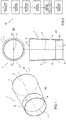
- number 1 denotes as a whole a capsule 1 for smoking articles, in particular for filters, designed to contain a liquid to be used in the cooling of smoke.
- the capsule 1 is designed to contain water or a mixture of water and a flavour.
- the capsule 1 comprises a cup-shaped body 2 preferably made in one piece, for example made of plastic material, defined by a tubular side wall 4 and, at one end, by a circular bottom wall 5 or bottom element.
- the cup-shaped body 2 has a shape slightly tapered towards the bottom wall 5.
- the cup-shaped body 2 has a substantially cylindrical shape.
- the side wall 4 has a longitudinal axis 3 and delimits, with the bottom wall 5, a compartment 6, which is adapted to contain a predetermined amount of liquid.
- the side wall 4 has a circular shape in plan.
- the side wall 4 is provided with a plurality of ribs (not illustrated) which extend in a cantilever fashion from the outer surface of the side wall 4, extend over the entire length of the side wall 4 and are uniformly distributed around the longitudinal axis 3.
- the bottom wall 5 is connected at a height h of the side wall 4.
- the bottom wall 5 is not arranged flush with the lower edge 9 of the side wall 4 but fits at a height h with respect to said lower edge 9.
- the connection between the bottom wall 5 and the inner surface of the side wall 4 is obtained by means of a weakened profile 5* (of reduced thickness) to allow, in use, the breakage under the action of a force imparted from the outside in order to pour out the liquid contained inside the compartment 6.
- the compartment 6 is open at the top and is closed by a cover 7 conveniently formed by a film or a wrap made of PET/PE.
- the capsule 1 comprises, furthermore, a collar defined by the upper surface of the side wall 4 to which the cover 7 is connected.
- the capsule 1 comprises a collar defined by an annular flange (not illustrated), which extends in a cantilever fashion from the end of the side wall 4 opposite the bottom wall 5 and is arranged on a plane orthogonal to said longitudinal axis 3.
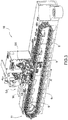
- Figure 2 number 10 denotes, as a whole, a manufacturing machine for the production of the capsules 1 for smoking articles described above, which travel a forming path via a moulding station S1 of the semi-finished capsules 1 and, in particular, of the cup-shaped bodies 2, one or more check and control stations S2 for the collars and for the bottom walls 5, a transfer station S3 for transferring the cup-shaped bodies 2 into trays 9, a filling station S4 for filling the cup-shaped bodies 2 with the liquid, a coupling station S5 for coupling the cup-shaped bodies 2 to the covering elements 7 and a welding station S6 for welding the covering elements 7 to the respective cup-shaped bodies 2.
- the manufacturing machine 10 comprises a feeding system 11 which develops along a closed loop working path and comprises the filling station S4 with the liquid, the coupling station S5 for coupling the cup-shaped bodies 2 to the covering elements 7 and the welding station S6 for welding the covering elements 7 to the respective cup-shaped bodies 2 arranged along said feeding system 11.
- the feeding system 11 is made by means of a conveyor 11 which receives the cup-shaped bodies 2 exiting the transfer station S3, and feeds them along the feeding direction A into trays 9 up to the next filling station S4 with the liquid.
- the trays 9 have a plurality of pockets 12, each designed to receive and house a respective cup-shaped body 2; the pockets 12 are typically divided into several rows equidistant from one another and distributed over the entire available surface of the tray 9. For example, in each tray 9 ninety-six pockets 12 are obtained, divided into eight rows of twelve pockets 12 each.
- the pockets 12 are open at the bottom; in other words, each pocket 12 is defined by a through cavity formed in the tray 9 and is delimited by an inner surface 13 coaxial with an axis X (visible in Figure 8 ).
- the coupling station S5 comprises a transfer drum 14 connected to a fixed frame 15 above which a strip 16 of plastic material is fed with an intermittent motion.
- the transfer drum 14 is formed by a central body 17 which rotates with intermittent motion around a substantially horizontal rotation axis R and supports a pair of movable fittings 18, denoted with 18A and 18B, which are equal and diametrically opposite to each other in respect to the rotation axis R, each of which is movable with respect to the central body 17 along the vertical direction S, orthogonal to the rotation axis R and to the feeding direction A so as to move between a transfer position (assumed during the rotations of the central body 17 around to the rotation axis R and illustrated in Figure 7 ) and a working position (assumed during the stopping step of the central body 17 and illustrated in Figures 4 and 5 ), and vice versa.
- a transfer position assumed during the rotations of the central body 17 around to the rotation axis R and illustrated in Figure 7
- a working position assumed during the stopping step of the central body 17 and illustrated in Figures 4 and 5
- Each movable fitting 18 supports a sucking holding plate 19 provided with a plurality of sucking heads 20 formed as tubular ducts parallel to each other.
- the arrangement of the sucking heads 20 reproduces the arrangement of the pockets 12 in the trays 9.
- each movable fitting 18 comprises ninety-six sucking heads 20 divided into eight rows of twelve sucking heads 20 each.
- the transfer drum 14 has a pneumatic suction and blowing system provided with a sucking pump (not illustrated), which is connected to each sucking head 20 by means of a respective suction duct so as to place each sucking head 20 in communication with the sucking pump.
- the coupling station S5 is in turn divided into a cutting area S5' for cutting the covering elements 7 and a transfer area S5" for transferring the covering elements 7 into the pockets 12.
- the cutting area S5' for cutting the covering elements 7 is arranged at the upper part of the transfer drum 14 while the transfer area S5" for transferring the covering elements 7 is diametrically opposite to the cutting area S5' and obtained at the lower part of the transfer drum 14 facing the conveyor 11 which feeds the cup-shaped bodies 2 into the trays 9.
- each movable fitting 18 cooperates with a cutting member 21 so as to obtain the covering elements 7;
- the cutting member 21 comprises, in turn, a cutting device 22 in which a plate 23 is provided with a plurality of cutting elements 24 formed as mutually parallel tubular bodies and provided, at one end, with a respective sharp edge.
- the arrangement of the cutting elements 24 reproduces the arrangement of the pockets 12 inside the trays 9 and of the sucking heads 20.
- the cutting member 21 comprises ninety-six cutting elements 24 divided into eight rows of twelve cutting elements 24 each.
- the plate 23 is movable between two positions along the vertical direction S.
- the plate 23 is movable between a rest position and an advanced cutting position, and vice versa.
- the movement of the plate 23 is directly controlled by an eccentric element 25 which receives motion from suitable actuation means.
- the cutting member 21 further comprises a fixed frame 26 connected to the eccentric element 25 and a movable frame 27, in turn comprising a guide system 28 preferably provided with ball bushings, carried by the fixed frame 26, arranged according to the corners of a parallelepiped defined by the frame 26 and connected to the fixed frame 15.
- the fixed frame 15 is interposed between the cutting member 21 and the transfer drum 14; an upper surface of the fixed frame 15 defines a plane for feeding the strip 16 of plastic material unwound by a reel.
- the waste of the strip 16 of plastic material is again rewound onto a reel through a plurality of return rollers or, alternatively, the waste of the strip 16 of plastic material is shredded.
- a plurality of through openings 30 are formed, which are provided with respective axes X', substantially vertical and parallel to each other, inside which the sucking heads 20, in use, slide.
- the arrangement of the through openings 30 reproduces the arrangement of the pockets 12 in the trays 9, of the sucking heads 20 and of the cutting elements 24.
- the through openings 30 are arranged at the cutting elements 24; in particular, each through opening 30 is directly facing a respective cutting element 24. Even more in detail, in the fixed frame 15 ninety-six through openings 30 are obtained, which are divided into eight rows of twelve through openings 30 each.
- the transfer drum 24 comprises an actuator system 31 for the movable fittings 18, which is obtained by means of an arm 32 connected to the central body 17 and rotatable relative to the central body 17 around the rotation axis R.
- Each of the two movable fittings 18 is connected to a respective support bracket 33, having, in front view, a substantially L-shape.
- Each support bracket 33 has an inner profile complementary to the profile of the arm 32.
- Each support bracket 33 is connected to a respective end portion of the arm 32 with the interposition of a connecting rod 34.
- Each connecting rod 34 is rigidly connected with a first end to the corresponding support bracket 33 by means of suitable fixing means and, with a second end thereof, to the respective end portion of the arm 32 by means of suitable fixing means.
- Each connecting rod 34 can be connected alternately to a front surface or to a rear surface of the corresponding support bracket 33 and to the corresponding end portion of the arm 32.
- the transfer drum 14 performs a 180° rotation around its rotation axis R and stops, thus arranging the movable fitting 18A in the cutting area S5' and the movable fitting 18B at the transfer area S5" of the covering elements 7.
- the arm 32 performs a partial rotation in a clockwise (or possibly anti-clockwise) direction around the rotation axis R so as to arrange both movable fittings 18 in the working position.
- the sucking holding plate 19 is raised and each sucking head 20 is inserted inside a respective through opening 30.
- the movement of the plate 23 which moves downwards from the rest position to the advanced cutting position along the vertical direction S is controlled, thus intercepting the strip 16 of plastic material and obtaining for each cutting element 24 a respective covering element 7.
- the pneumatic system is activated so that each sucking head 20 holds the respective covering element 7.
- the movement of the plate 23, which moves upwards from the advanced cutting position to the rest position along the vertical direction S, is therefore controlled, and, at the same time, the arm 32 performs a partial rotation in an anti-clockwise (or clockwise) direction around the rotation axis R so as to place both movable fittings 18 in the moving position and extract the sucking heads 20 of the movable fitting 18A from the respective through openings 30.
- the transfer drum 24 then rotates by 180° around the rotation axis R and stops, thus arranging the movable fitting 18B at the cutting area S5' and the movable fitting 18A at the transfer area S5" of the covering elements 7.
- the movable fitting 18A stops in a position directly facing a tray 9. While the transfer drum 24 is still, the arm 32 again performs the partial rotation in a clockwise (or anti-clockwise) direction around the rotation axis R so as to be arranged in the working position in which each sucking head 20 is arranged, facing and near a respective pocket 12.
- the suction of the pneumatic system is then deactivated so that each covering element 7 is received inside a respective pocket 12 of the tray 9; to facilitate the transfer of the covering element 7 inside the respective pocket 12, the blowing of the pneumatic system is activated simultaneously with the deactivation of the suction.
- the movement of the arm 32, which performs the partial rotation in an anti-clockwise (or clockwise) direction around the rotation axis R is then again controlled, so as to be arranged in the movement position.
- the transfer drum 24 then rotates by 180° around its rotation axis R in order to return back to the position where the movable fitting 18A is arranged, at the cutting area S5', and the movable fitting 18B is arranged at the transfer area S5" of the covering elements 7.
- the inner surface 13 of the pockets 12 has an annular abutment 35 designed to define a seat in which the covering element 7 is housed above the respective cup-shaped body 2.
- the surface 13 does not have a constant diameter and is, on the contrary, divided into a lower portion 13** designed to house a respective cup-shaped body 2 and an upper portion 13*, which has a diameter larger than the lower portion 13**, in which the covering elements 7 can be housed.
- the tray 9 is again conveyed along the feeding direction A until it stops at the welding station S6 for welding the covering elements 7 to the cup-shaped bodies 2.
- the welding station S6 comprises a welding unit 36 obtained through a support 37, movable in the vertical direction S, provided with a suction circuit obtained through a plurality of suction heads 38, and a sucking pump (not illustrated) which is connected to each suction head 38 via a respective suction duct so as to place each suction head 38 in communication with the sucking pump.
- each suction head 38 comprises a body 39 that longitudinally develops along a vertical axis and comprises an end arranged so as to contact a corresponding covering element 7.
- the arrangement of the suction heads 38 reproduces the arrangement of the pockets 12 inside the trays 9.
- the movable support 37 comprises ninety-six suction heads 38 divided into eight rows of twelve suction heads 38 each.
- Each suction head 38 cooperates with a respective striker element 41 for lifting the cup-shaped bodies 2 towards the suction head 38.
- the striker elements 41 are connected to a common support 42, which is also movable along the vertical direction S.
- the arrangement of the striker elements 41 reproduces the arrangement of the pockets 12 inside the trays 9 and of the suction heads 38.
- the support 42 comprises ninety-six striker elements 41 divided into eight rows of twelve striker elements 41 each.
- Each suction head 38 cooperates with a respective welder 43, for example a sonotrode, so as to obtain the weld of the covering element 7 to the cup-shaped body 2, for example by means of ultrasound.
- a respective welder 43 is cooperating with a respective assembly formed by the suction head 38 and the respective striker element 41.
- the welders 43 are carried by a common support element 44, also movable in the vertical direction S, provided with a plurality of welders 43.
- the support element 44 comprises ninety-six welders 43 divided into eight rows of twelve welders 43 each.
- the welding station S6 can comprise a welding unit obtained by means a movable support in the vertical direction S provided with a plurality of striker heads each comprising a body that longitudinally develops along a vertical axis and comprises an end arranged to contact a corresponding covering element 7 (said striker heads are similar to the suction heads 38 previously described but do not provide suction).
- the arrangement of the striker heads reproduces the arrangement of the pockets 12 inside the trays 9.
- the movable support comprises ninety-six striker heads divided into eight rows of twelve striker heads each.
- the activation step of the suction circuit ensures that each covering element 7 is held by means of suction by the suction head 38 and the actual welding step takes place substantially simultaneously. In this way a uniform welding of the covering element 7 is obtained on the collar 8.
- a uniform welding of the covering element 7 is obtained on the collar 8.
- by crushing the capsule 1 it is ensured that the latter collapses at the bottom wall.
- the detachment of the covering element 7 from the collar is determined; this would cause a wrong outlet direction of the liquid from the capsule 1.
- the manufacturing machine 10 described up to now has various advantages. In particular, it allows the handling of small components such as the cup-shaped bodies 2 and the covering elements 7, while ensuring good performance in terms of productivity and without compromising the quality of the welding of the covering elements 7 to the respective cup-shaped bodies 2.
Landscapes
- Engineering & Computer Science (AREA)
- Mechanical Engineering (AREA)
- Lining Or Joining Of Plastics Or The Like (AREA)
Claims (13)
- Machine de fabrication (10) pour la production de capsules (1) pour articles à fumer, en particulier pour des filtres, conçues pour contenir un liquide à utiliser pour le refroidissement de la fumée ; où chaque capsule (1) comprend un corps en forme de coupelle (2) qui est défini par une paroi latérale (4) et, au niveau d'une extrémité, par une paroi inférieure (5) ; la paroi latérale (4) a un axe longitudinal (3) et délimite, avec la paroi inférieure (5), un compartiment (6) qui est conçu pour contenir une quantité prédéterminée de liquide ; la capsule (1) comprenant un élément de recouvrement (7) qui est couplé à une partie de la paroi latérale (4) définissant un collier dans la zone de l'extrémité opposée à la paroi inférieure (5) ; la machine de fabrication (10) comprenant :un système d'alimentation (11) qui amène les capsules semi-finies (1) le long d'une trajectoire de formation ;un certain nombre de stations opérationnelles (S4, S5, S6) qui sont agencées le long de la trajectoire de formation et comprennent une station de couplage (S5) pour coupler les éléments de recouvrement (7) aux corps en forme de coupelle (2) ; où la station de couplage (S5) comprend un tambour de transfert (14) qui tourne autour d'un axe de rotation (R) avec un mouvement intermittent et au-dessus duquel une bande (16) en matière plastique est alimentée ; le tambour de transfert (14) supporte une paire de raccords mobiles (18) qui sont conçus pour coopérer avec un organe de coupe (21) afin d'obtenir les éléments de recouvrement (7) à partir de la bande (16) en matière plastique, les maintenir au moyen d'aspiration pendant une rotation à 180° autour de l'axe de rotation (R) et les transférer vers le système d'alimentation (11) ; etune station de soudage (S6) pour souder les éléments de recouvrement (7) sur les corps en forme de coupelle (2), qui est agencée en aval de la station de couplage (S5) ;la machine étant caractérisée en ce que les éléments de recouvrement (7) sont transférés dans des poches (12) respectives du système d'alimentation (11) et chacune desdites poches (12) contient un corps en forme de coupelle (2) respectif et dans la surface interne (13) de chaque poche (12) est formée une butée annulaire (35), qui est conçue pour définir un siège pour l'élément de recouvrement (7) au-dessus du corps en forme de coupelle (2) respectif.
- Machine selon la revendication 1, dans laquelle chaque raccord mobile (18) supporte une plaque de maintien d'aspiration (19) qui est prévue avec une pluralité de têtes d'aspiration (20) ; et dans laquelle le tambour de transfert (14) a un dispositif d'aspiration qui est prévu avec une pompe d'aspiration qui est raccordée à chaque tête d'aspiration (20).
- Machine selon la revendication 2, dans laquelle l'organe de coupe (21) comprend, à son tour, un dispositif de coupe (22), où un premier support (23) se déplaçant le long d'une direction sensiblement verticale (S) porte une pluralité d'éléments de coupe (24) raccordés à ce dernier ; l'agencement desdits éléments de coupe (24) reproduit l'agencement des têtes d'aspiration (20), de sorte que chaque élément de coupe (24) coopère avec une tête d'aspiration (20) respective afin d'obtenir un élément de recouvrement (7).
- Machine selon la revendication 2 ou 3, et comprenant un bâti fixe (15) intercalé entre l'élément de coupe (21) et le tambour de transfert (14) et dont la surface supérieure définit un plan d'alimentation pour la bande (16) en matière plastique ; dans laquelle, dans le bâti fixe (15), une pluralité d'ouvertures débouchantes (30) sont obtenues, dont l'agencement reproduit l'agencement des têtes d'aspiration (20) et à l'intérieur desquelles les têtes d'aspiration (20) coulissent le long de la direction sensiblement verticale (S).
- Machine selon l'une quelconque des revendications précédentes, dans laquelle le tambour de transfert (24) comprend un corps central (17) et un système d'actionneur (31) pour les raccords mobiles (18) qui est obtenu au moyen d'un bras (32) raccordé au corps central (17) et pouvant tourner par rapport au corps central (17) autour de l'axe de rotation (R) .
- Machine selon la revendication 5, dans laquelle chacun des deux raccords mobiles (18) est raccordé à une console de support (33) respective qui a un profil interne qui est complémentaire du profil du bras (32).
- Machine selon l'une quelconque des revendications précédentes, dans laquelle chaque raccord mobile (18) supporte une plaque de maintien d'aspiration (19) prévue avec une pluralité de têtes d'aspiration (20) ; et dans laquelle l'agencement desdites poches (12) reproduit l'agencement des têtes d'aspiration (20).
- Machine selon l'une quelconque des revendications précédentes, dans laquelle les poches (12) sont obtenues dans des plateaux (9) qui sont alimentés par le système d'alimentation (11) le long de la trajectoire de formation.
- Machine selon l'une quelconque des revendications précédentes, dans laquelle la station de soudage (S6) comprend une unité de soudage (36) comprenant un support (44) qui est mobile le long d'une direction sensiblement verticale (S) et est prévu avec une pluralité de machines à souder (43) afin de souder simultanément une pluralité d'éléments de recouvrement (7) sur les corps en forme de coupelle (2) respectifs.
- Machine selon la revendication 9, dans laquelle l'unité de soudage (36) est prévue avec une pluralité de têtes d'aspiration (38) pour percuter l'élément de recouvrement (7) respectif, et dans laquelle chacune des têtes d'aspiration (38) coopère avec une machine à souder (43) respective.
- Machine selon la revendication 10, dans laquelle l'unité de soudage (36) est prévue avec un dispositif d'aspiration comprenant une pompe d'aspiration, qui est raccordée aux têtes d'aspiration (38) afin de maintenir, au moyen de l'aspiration, l'élément de recouvrement (7) respectif.
- Machine selon la revendication 10 ou 11, dans laquelle chaque tête d'aspiration (38) coopère avec un élément de percussion (41) respectif conçu pour lever les corps en forme de coupelle (2) et supporter lesdits corps en forme de coupelle (2) pendant l'étape de soudage.
- Procédé pour la production de capsules (1) pour articles à fumer, en particulier pour des filtres, conçues pour contenir un liquide à utiliser pour le refroidissement de la fumée, mis en œuvre par une machine réalisée selon l'une quelconque des revendications 1 à 12 ; où chaque capsule (1) comprend un corps en forme de coupelle (2) défini par une paroi latérale (4) et, au niveau d'une extrémité, par une paroi inférieure (5) ; la paroi latérale (4) a un axe longitudinal (3) et délimite, avec la paroi inférieure (5), un compartiment (6) qui est conçu pour contenir une quantité prédéterminée de liquide ; la capsule (1) comprenant un élément de recouvrement (7) qui est couplé à une partie de la paroi latérale (4) définissant un collier au niveau de l'extrémité opposée à la paroi inférieure (5) ; le procédé comprend les étapes consistant à :amener les corps en forme de coupelle (2) le long d'une trajectoire de formation à l'intérieur de poches (12) respectives d'un système d'alimentation (11) ;obtenir les éléments de recouvrement (7) en coupant une bande (16) en matière plastique ;maintenir les éléments de recouvrement (7) au moyen de l'aspiration pendant une rotation à 180° autour d'un axe de rotation (R) ;transférer chaque élément de recouvrement (7) dans une poche (12) respective du système d'alimentation (11) ;souder les éléments de recouvrement (7) sur les corps en forme de coupelle (2) respectifs.
Applications Claiming Priority (1)
| Application Number | Priority Date | Filing Date | Title |
|---|---|---|---|
| IT102017000085374A IT201700085374A1 (it) | 2017-07-26 | 2017-07-26 | Metodo e macchina confezionatrice per la produzione di capsule per articoli da fumo, in particolare per filtri, realizzate per contenere un liquido da impiegare nel raffreddamento dei fumi |
Publications (2)
| Publication Number | Publication Date |
|---|---|
| EP3434455A1 EP3434455A1 (fr) | 2019-01-30 |
| EP3434455B1 true EP3434455B1 (fr) | 2021-05-12 |
Family
ID=60451079
Family Applications (1)
| Application Number | Title | Priority Date | Filing Date |
|---|---|---|---|
| EP18185895.2A Active EP3434455B1 (fr) | 2017-07-26 | 2018-07-26 | Procédé et machine de production de capsules pour articles à fumer, notamment pour des filtres, conçues pour contenir un liquide destiné à être utilisé dans le refroidissement de la fumée |
Country Status (2)
| Country | Link |
|---|---|
| EP (1) | EP3434455B1 (fr) |
| IT (1) | IT201700085374A1 (fr) |
Families Citing this family (1)
| Publication number | Priority date | Publication date | Assignee | Title |
|---|---|---|---|---|
| BR112023004705A2 (pt) | 2020-09-15 | 2023-05-09 | Rychiger Ag | Aparelho para a fabricação de um filtro para cápsulas descartáveis para a preparação de bebidas |
Family Cites Families (3)
| Publication number | Priority date | Publication date | Assignee | Title |
|---|---|---|---|---|
| JPH05330503A (ja) * | 1992-05-29 | 1993-12-14 | Japan Tobacco Inc | 円筒状容器の上蓋ヒートシール装置 |
| FR2827835B1 (fr) * | 2001-07-26 | 2003-12-19 | Erca Formseal | Dispositif pour decouper une rangee d'opercules dans une bande a opercules et les fixer sur une rangee de recipients remplis |
| JP5885318B2 (ja) * | 2012-10-15 | 2016-03-15 | 日本たばこ産業株式会社 | 液体を封入したカプセル及びこのカプセルを備えた喫煙物品 |
-
2017
- 2017-07-26 IT IT102017000085374A patent/IT201700085374A1/it unknown
-
2018
- 2018-07-26 EP EP18185895.2A patent/EP3434455B1/fr active Active
Non-Patent Citations (1)
| Title |
|---|
| None * |
Also Published As
| Publication number | Publication date |
|---|---|
| EP3434455A1 (fr) | 2019-01-30 |
| IT201700085374A1 (it) | 2019-01-26 |
Similar Documents
| Publication | Publication Date | Title |
|---|---|---|
| EP3145817B1 (fr) | Unité pour alimenter des éléments de fermeture conçus pour fermer des récipients en forme de gobelet, poste et procédé pour fermer les récipients en forme de gobelet | |
| EP1539588B1 (fr) | Procede et dispositif permettant de former des etiquettes tubulaires composees d'une feuille thermoretractable, et d'inserer des contenants dans celles-ci | |
| US10500782B2 (en) | Rotary machine comprising first stations and second stations rotating around a single main axis | |
| JP2008264549A (ja) | 微小のタブレット状の物品、特に医薬品を複数のカプセル等に充填するための方法並びにマシン | |
| JPH02242716A (ja) | パック容器の反転装置 | |
| JP4332779B2 (ja) | 容器の外装用チューブ嵌装装置 | |
| JP5661360B2 (ja) | 紙容器用トランスファー装置 | |
| EP3434455A1 (fr) | Procédé et machine de production de capsules pour articles à fumer, notamment pour des filtres, conçues pour contenir un liquide destiné à être utilisé dans le refroidissement de la fumée | |
| EP3424670B1 (fr) | Procédé et machine de fabrication pour la production de capsules pour articles à fumer, notamment pour des filtres, conçues pour contenir un liquide destiné à être utilisé dans le refroidissement de la fumée | |
| CN102229517A (zh) | 一种工业粉状炸药装药工艺及其装药机组 | |
| JP2002019710A (ja) | 蓋の供給装置 | |
| JP2016069050A (ja) | フィルム被嵌ヘッド | |
| US4346515A (en) | Telescopic mating apparatus | |
| EP3434456B1 (fr) | Procédé et machine de production de capsules pour articles à fumer, notamment pour des filtres, conçues pour contenir un liquide destiné à être utilisé dans le refroidissement de la fumée | |
| ITBO980276A1 (it) | Unita' orientatrice ed alimentatrice di fondelli per capsule medicinal i. | |
| JP2023535116A (ja) | 少なくとも1つの構成部品および少なくとも1つの容器を保持および移動するためのユニットおよび方法、ならびにそれに関連付けられた物品のための製造装置 | |
| CN202011844U (zh) | 一种工业粉状炸药装药机组 | |
| JPH0551012A (ja) | 豆腐等のパツク詰め装置 | |
| JP3148067B2 (ja) | 長寸の柔軟な材料から前記柔軟な材料からなる管部材を提供する方法及び装置 | |
| US3176823A (en) | Transfer mechanism for tubular articles | |
| EP3424669B1 (fr) | Procédé et machine de fabrication pour la production de capsules pour articles à fumer, notamment pour filtres, conçus pour contenir un liquide destiné à être utilisé lors du refroidissement de la fumée | |
| KR100515697B1 (ko) | 파우치용기 자동 이송장치 | |
| JPH11227730A (ja) | ラベル開口装置及びそのラベル開口装置を用いたロータリ型ラベル嵌挿装置 | |
| JP4973838B2 (ja) | カップ型容器の排出装置 | |
| JPH0742972Y2 (ja) | シュリンク包装装置 |
Legal Events
| Date | Code | Title | Description |
|---|---|---|---|
| PUAI | Public reference made under article 153(3) epc to a published international application that has entered the european phase |
Free format text: ORIGINAL CODE: 0009012 |
|
| STAA | Information on the status of an ep patent application or granted ep patent |
Free format text: STATUS: THE APPLICATION HAS BEEN PUBLISHED |
|
| AK | Designated contracting states |
Kind code of ref document: A1 Designated state(s): AL AT BE BG CH CY CZ DE DK EE ES FI FR GB GR HR HU IE IS IT LI LT LU LV MC MK MT NL NO PL PT RO RS SE SI SK SM TR |
|
| AX | Request for extension of the european patent |
Extension state: BA ME |
|
| STAA | Information on the status of an ep patent application or granted ep patent |
Free format text: STATUS: REQUEST FOR EXAMINATION WAS MADE |
|
| 17P | Request for examination filed |
Effective date: 20190729 |
|
| RBV | Designated contracting states (corrected) |
Designated state(s): AL AT BE BG CH CY CZ DE DK EE ES FI FR GB GR HR HU IE IS IT LI LT LU LV MC MK MT NL NO PL PT RO RS SE SI SK SM TR |
|
| GRAP | Despatch of communication of intention to grant a patent |
Free format text: ORIGINAL CODE: EPIDOSNIGR1 |
|
| STAA | Information on the status of an ep patent application or granted ep patent |
Free format text: STATUS: GRANT OF PATENT IS INTENDED |
|
| RIC1 | Information provided on ipc code assigned before grant |
Ipc: B65B 7/16 20060101ALI20201105BHEP Ipc: B29C 69/00 20060101AFI20201105BHEP Ipc: B65B 7/28 20060101ALI20201105BHEP Ipc: B29C 65/02 20060101ALN20201105BHEP Ipc: B65B 41/06 20060101ALI20201105BHEP Ipc: A24D 3/06 20060101ALN20201105BHEP Ipc: B65B 7/01 20060101ALI20201105BHEP Ipc: B29C 65/78 20060101ALN20201105BHEP Ipc: B29L 31/00 20060101ALN20201105BHEP |
|
| RIC1 | Information provided on ipc code assigned before grant |
Ipc: B29L 31/00 20060101ALN20201110BHEP Ipc: B29C 65/78 20060101ALN20201110BHEP Ipc: B29C 69/00 20060101AFI20201110BHEP Ipc: B65B 7/16 20060101ALI20201110BHEP Ipc: B65B 7/01 20060101ALI20201110BHEP Ipc: B29C 65/02 20060101ALN20201110BHEP Ipc: B65B 41/06 20060101ALI20201110BHEP Ipc: B65B 7/28 20060101ALI20201110BHEP Ipc: A24D 3/06 20060101ALN20201110BHEP |
|
| INTG | Intention to grant announced |
Effective date: 20201204 |
|
| RIC1 | Information provided on ipc code assigned before grant |
Ipc: B65B 7/28 20060101ALI20201123BHEP Ipc: B65B 41/06 20060101ALI20201123BHEP Ipc: B65B 7/01 20060101ALI20201123BHEP Ipc: A24D 3/06 20060101ALN20201123BHEP Ipc: B29L 31/00 20060101ALN20201123BHEP Ipc: B29C 65/78 20060101ALN20201123BHEP Ipc: B29C 65/02 20060101ALN20201123BHEP Ipc: B65B 7/16 20060101ALI20201123BHEP Ipc: B29C 69/00 20060101AFI20201123BHEP |
|
| GRAS | Grant fee paid |
Free format text: ORIGINAL CODE: EPIDOSNIGR3 |
|
| GRAA | (expected) grant |
Free format text: ORIGINAL CODE: 0009210 |
|
| STAA | Information on the status of an ep patent application or granted ep patent |
Free format text: STATUS: THE PATENT HAS BEEN GRANTED |
|
| AK | Designated contracting states |
Kind code of ref document: B1 Designated state(s): AL AT BE BG CH CY CZ DE DK EE ES FI FR GB GR HR HU IE IS IT LI LT LU LV MC MK MT NL NO PL PT RO RS SE SI SK SM TR |
|
| REG | Reference to a national code |
Ref country code: GB Ref legal event code: FG4D |
|
| REG | Reference to a national code |
Ref country code: CH Ref legal event code: EP |
|
| REG | Reference to a national code |
Ref country code: DE Ref legal event code: R096 Ref document number: 602018016955 Country of ref document: DE |
|
| REG | Reference to a national code |
Ref country code: IE Ref legal event code: FG4D |
|
| REG | Reference to a national code |
Ref country code: AT Ref legal event code: REF Ref document number: 1391902 Country of ref document: AT Kind code of ref document: T Effective date: 20210615 |
|
| REG | Reference to a national code |
Ref country code: LT Ref legal event code: MG9D |
|
| REG | Reference to a national code |
Ref country code: AT Ref legal event code: MK05 Ref document number: 1391902 Country of ref document: AT Kind code of ref document: T Effective date: 20210512 |
|
| REG | Reference to a national code |
Ref country code: NL Ref legal event code: MP Effective date: 20210512 |
|
| PG25 | Lapsed in a contracting state [announced via postgrant information from national office to epo] |
Ref country code: BG Free format text: LAPSE BECAUSE OF FAILURE TO SUBMIT A TRANSLATION OF THE DESCRIPTION OR TO PAY THE FEE WITHIN THE PRESCRIBED TIME-LIMIT Effective date: 20210812 Ref country code: AT Free format text: LAPSE BECAUSE OF FAILURE TO SUBMIT A TRANSLATION OF THE DESCRIPTION OR TO PAY THE FEE WITHIN THE PRESCRIBED TIME-LIMIT Effective date: 20210512 Ref country code: FI Free format text: LAPSE BECAUSE OF FAILURE TO SUBMIT A TRANSLATION OF THE DESCRIPTION OR TO PAY THE FEE WITHIN THE PRESCRIBED TIME-LIMIT Effective date: 20210512 Ref country code: HR Free format text: LAPSE BECAUSE OF FAILURE TO SUBMIT A TRANSLATION OF THE DESCRIPTION OR TO PAY THE FEE WITHIN THE PRESCRIBED TIME-LIMIT Effective date: 20210512 Ref country code: LT Free format text: LAPSE BECAUSE OF FAILURE TO SUBMIT A TRANSLATION OF THE DESCRIPTION OR TO PAY THE FEE WITHIN THE PRESCRIBED TIME-LIMIT Effective date: 20210512 |
|
| PG25 | Lapsed in a contracting state [announced via postgrant information from national office to epo] |
Ref country code: PT Free format text: LAPSE BECAUSE OF FAILURE TO SUBMIT A TRANSLATION OF THE DESCRIPTION OR TO PAY THE FEE WITHIN THE PRESCRIBED TIME-LIMIT Effective date: 20210913 Ref country code: NO Free format text: LAPSE BECAUSE OF FAILURE TO SUBMIT A TRANSLATION OF THE DESCRIPTION OR TO PAY THE FEE WITHIN THE PRESCRIBED TIME-LIMIT Effective date: 20210812 Ref country code: LV Free format text: LAPSE BECAUSE OF FAILURE TO SUBMIT A TRANSLATION OF THE DESCRIPTION OR TO PAY THE FEE WITHIN THE PRESCRIBED TIME-LIMIT Effective date: 20210512 Ref country code: PL Free format text: LAPSE BECAUSE OF FAILURE TO SUBMIT A TRANSLATION OF THE DESCRIPTION OR TO PAY THE FEE WITHIN THE PRESCRIBED TIME-LIMIT Effective date: 20210512 Ref country code: RS Free format text: LAPSE BECAUSE OF FAILURE TO SUBMIT A TRANSLATION OF THE DESCRIPTION OR TO PAY THE FEE WITHIN THE PRESCRIBED TIME-LIMIT Effective date: 20210512 Ref country code: SE Free format text: LAPSE BECAUSE OF FAILURE TO SUBMIT A TRANSLATION OF THE DESCRIPTION OR TO PAY THE FEE WITHIN THE PRESCRIBED TIME-LIMIT Effective date: 20210512 Ref country code: GR Free format text: LAPSE BECAUSE OF FAILURE TO SUBMIT A TRANSLATION OF THE DESCRIPTION OR TO PAY THE FEE WITHIN THE PRESCRIBED TIME-LIMIT Effective date: 20210813 Ref country code: IS Free format text: LAPSE BECAUSE OF FAILURE TO SUBMIT A TRANSLATION OF THE DESCRIPTION OR TO PAY THE FEE WITHIN THE PRESCRIBED TIME-LIMIT Effective date: 20210912 |
|
| PG25 | Lapsed in a contracting state [announced via postgrant information from national office to epo] |
Ref country code: NL Free format text: LAPSE BECAUSE OF FAILURE TO SUBMIT A TRANSLATION OF THE DESCRIPTION OR TO PAY THE FEE WITHIN THE PRESCRIBED TIME-LIMIT Effective date: 20210512 |
|
| PG25 | Lapsed in a contracting state [announced via postgrant information from national office to epo] |
Ref country code: CZ Free format text: LAPSE BECAUSE OF FAILURE TO SUBMIT A TRANSLATION OF THE DESCRIPTION OR TO PAY THE FEE WITHIN THE PRESCRIBED TIME-LIMIT Effective date: 20210512 Ref country code: DK Free format text: LAPSE BECAUSE OF FAILURE TO SUBMIT A TRANSLATION OF THE DESCRIPTION OR TO PAY THE FEE WITHIN THE PRESCRIBED TIME-LIMIT Effective date: 20210512 Ref country code: RO Free format text: LAPSE BECAUSE OF FAILURE TO SUBMIT A TRANSLATION OF THE DESCRIPTION OR TO PAY THE FEE WITHIN THE PRESCRIBED TIME-LIMIT Effective date: 20210512 Ref country code: SK Free format text: LAPSE BECAUSE OF FAILURE TO SUBMIT A TRANSLATION OF THE DESCRIPTION OR TO PAY THE FEE WITHIN THE PRESCRIBED TIME-LIMIT Effective date: 20210512 Ref country code: SM Free format text: LAPSE BECAUSE OF FAILURE TO SUBMIT A TRANSLATION OF THE DESCRIPTION OR TO PAY THE FEE WITHIN THE PRESCRIBED TIME-LIMIT Effective date: 20210512 Ref country code: ES Free format text: LAPSE BECAUSE OF FAILURE TO SUBMIT A TRANSLATION OF THE DESCRIPTION OR TO PAY THE FEE WITHIN THE PRESCRIBED TIME-LIMIT Effective date: 20210512 Ref country code: EE Free format text: LAPSE BECAUSE OF FAILURE TO SUBMIT A TRANSLATION OF THE DESCRIPTION OR TO PAY THE FEE WITHIN THE PRESCRIBED TIME-LIMIT Effective date: 20210512 |
|
| REG | Reference to a national code |
Ref country code: DE Ref legal event code: R097 Ref document number: 602018016955 Country of ref document: DE |
|
| REG | Reference to a national code |
Ref country code: CH Ref legal event code: PL |
|
| PLBE | No opposition filed within time limit |
Free format text: ORIGINAL CODE: 0009261 |
|
| STAA | Information on the status of an ep patent application or granted ep patent |
Free format text: STATUS: NO OPPOSITION FILED WITHIN TIME LIMIT |
|
| PG25 | Lapsed in a contracting state [announced via postgrant information from national office to epo] |
Ref country code: MC Free format text: LAPSE BECAUSE OF FAILURE TO SUBMIT A TRANSLATION OF THE DESCRIPTION OR TO PAY THE FEE WITHIN THE PRESCRIBED TIME-LIMIT Effective date: 20210512 |
|
| REG | Reference to a national code |
Ref country code: BE Ref legal event code: MM Effective date: 20210731 |
|
| 26N | No opposition filed |
Effective date: 20220215 |
|
| PG25 | Lapsed in a contracting state [announced via postgrant information from national office to epo] |
Ref country code: LI Free format text: LAPSE BECAUSE OF NON-PAYMENT OF DUE FEES Effective date: 20210731 Ref country code: CH Free format text: LAPSE BECAUSE OF NON-PAYMENT OF DUE FEES Effective date: 20210731 |
|
| PG25 | Lapsed in a contracting state [announced via postgrant information from national office to epo] |
Ref country code: IS Free format text: LAPSE BECAUSE OF FAILURE TO SUBMIT A TRANSLATION OF THE DESCRIPTION OR TO PAY THE FEE WITHIN THE PRESCRIBED TIME-LIMIT Effective date: 20210912 Ref country code: LU Free format text: LAPSE BECAUSE OF NON-PAYMENT OF DUE FEES Effective date: 20210726 Ref country code: FR Free format text: LAPSE BECAUSE OF NON-PAYMENT OF DUE FEES Effective date: 20210731 Ref country code: AL Free format text: LAPSE BECAUSE OF FAILURE TO SUBMIT A TRANSLATION OF THE DESCRIPTION OR TO PAY THE FEE WITHIN THE PRESCRIBED TIME-LIMIT Effective date: 20210512 |
|
| PG25 | Lapsed in a contracting state [announced via postgrant information from national office to epo] |
Ref country code: IT Free format text: LAPSE BECAUSE OF FAILURE TO SUBMIT A TRANSLATION OF THE DESCRIPTION OR TO PAY THE FEE WITHIN THE PRESCRIBED TIME-LIMIT Effective date: 20210512 Ref country code: IE Free format text: LAPSE BECAUSE OF NON-PAYMENT OF DUE FEES Effective date: 20210726 Ref country code: BE Free format text: LAPSE BECAUSE OF NON-PAYMENT OF DUE FEES Effective date: 20210731 |
|
| GBPC | Gb: european patent ceased through non-payment of renewal fee |
Effective date: 20220726 |
|
| PG25 | Lapsed in a contracting state [announced via postgrant information from national office to epo] |
Ref country code: GB Free format text: LAPSE BECAUSE OF NON-PAYMENT OF DUE FEES Effective date: 20220726 |
|
| PG25 | Lapsed in a contracting state [announced via postgrant information from national office to epo] |
Ref country code: CY Free format text: LAPSE BECAUSE OF FAILURE TO SUBMIT A TRANSLATION OF THE DESCRIPTION OR TO PAY THE FEE WITHIN THE PRESCRIBED TIME-LIMIT Effective date: 20210512 |
|
| PG25 | Lapsed in a contracting state [announced via postgrant information from national office to epo] |
Ref country code: HU Free format text: LAPSE BECAUSE OF FAILURE TO SUBMIT A TRANSLATION OF THE DESCRIPTION OR TO PAY THE FEE WITHIN THE PRESCRIBED TIME-LIMIT; INVALID AB INITIO Effective date: 20180726 |
|
| PG25 | Lapsed in a contracting state [announced via postgrant information from national office to epo] |
Ref country code: MK Free format text: LAPSE BECAUSE OF FAILURE TO SUBMIT A TRANSLATION OF THE DESCRIPTION OR TO PAY THE FEE WITHIN THE PRESCRIBED TIME-LIMIT Effective date: 20210512 |
|
| PG25 | Lapsed in a contracting state [announced via postgrant information from national office to epo] |
Ref country code: MT Free format text: LAPSE BECAUSE OF FAILURE TO SUBMIT A TRANSLATION OF THE DESCRIPTION OR TO PAY THE FEE WITHIN THE PRESCRIBED TIME-LIMIT Effective date: 20210512 |
|
| PGFP | Annual fee paid to national office [announced via postgrant information from national office to epo] |
Ref country code: DE Payment date: 20250729 Year of fee payment: 8 |
|
| PG25 | Lapsed in a contracting state [announced via postgrant information from national office to epo] |
Ref country code: TR Free format text: LAPSE BECAUSE OF FAILURE TO SUBMIT A TRANSLATION OF THE DESCRIPTION OR TO PAY THE FEE WITHIN THE PRESCRIBED TIME-LIMIT Effective date: 20210512 |