EP3435043A1 - Jauge radar et son procédé de fonctionnement - Google Patents
Jauge radar et son procédé de fonctionnement Download PDFInfo
- Publication number
- EP3435043A1 EP3435043A1 EP17183047.4A EP17183047A EP3435043A1 EP 3435043 A1 EP3435043 A1 EP 3435043A1 EP 17183047 A EP17183047 A EP 17183047A EP 3435043 A1 EP3435043 A1 EP 3435043A1
- Authority
- EP
- European Patent Office
- Prior art keywords
- transmission power
- signal
- control unit
- level gauge
- radar level
- Prior art date
- Legal status (The legal status is an assumption and is not a legal conclusion. Google has not performed a legal analysis and makes no representation as to the accuracy of the status listed.)
- Granted
Links
Images
Classifications
-
- G—PHYSICS
- G01—MEASURING; TESTING
- G01F—MEASURING VOLUME, VOLUME FLOW, MASS FLOW OR LIQUID LEVEL; METERING BY VOLUME
- G01F23/00—Indicating or measuring liquid level or level of fluent solid material, e.g. indicating in terms of volume or indicating by means of an alarm
- G01F23/22—Indicating or measuring liquid level or level of fluent solid material, e.g. indicating in terms of volume or indicating by means of an alarm by measuring physical variables, other than linear dimensions, pressure or weight, dependent on the level to be measured, e.g. by difference of heat transfer of steam or water
- G01F23/28—Indicating or measuring liquid level or level of fluent solid material, e.g. indicating in terms of volume or indicating by means of an alarm by measuring physical variables, other than linear dimensions, pressure or weight, dependent on the level to be measured, e.g. by difference of heat transfer of steam or water by measuring the variations of parameters of electromagnetic or acoustic waves applied directly to the liquid or fluent solid material
- G01F23/284—Electromagnetic waves
-
- G—PHYSICS
- G01—MEASURING; TESTING
- G01F—MEASURING VOLUME, VOLUME FLOW, MASS FLOW OR LIQUID LEVEL; METERING BY VOLUME
- G01F25/00—Testing or calibration of apparatus for measuring volume, volume flow or liquid level or for metering by volume
- G01F25/20—Testing or calibration of apparatus for measuring volume, volume flow or liquid level or for metering by volume of apparatus for measuring liquid level
-
- G—PHYSICS
- G01—MEASURING; TESTING
- G01S—RADIO DIRECTION-FINDING; RADIO NAVIGATION; DETERMINING DISTANCE OR VELOCITY BY USE OF RADIO WAVES; LOCATING OR PRESENCE-DETECTING BY USE OF THE REFLECTION OR RERADIATION OF RADIO WAVES; ANALOGOUS ARRANGEMENTS USING OTHER WAVES
- G01S13/00—Systems using the reflection or reradiation of radio waves, e.g. radar systems; Analogous systems using reflection or reradiation of waves whose nature or wavelength is irrelevant or unspecified
- G01S13/02—Systems using reflection of radio waves, e.g. primary radar systems; Analogous systems
- G01S13/06—Systems determining position data of a target
- G01S13/08—Systems for measuring distance only
-
- G—PHYSICS
- G01—MEASURING; TESTING
- G01S—RADIO DIRECTION-FINDING; RADIO NAVIGATION; DETERMINING DISTANCE OR VELOCITY BY USE OF RADIO WAVES; LOCATING OR PRESENCE-DETECTING BY USE OF THE REFLECTION OR RERADIATION OF RADIO WAVES; ANALOGOUS ARRANGEMENTS USING OTHER WAVES
- G01S13/00—Systems using the reflection or reradiation of radio waves, e.g. radar systems; Analogous systems using reflection or reradiation of waves whose nature or wavelength is irrelevant or unspecified
- G01S13/88—Radar or analogous systems specially adapted for specific applications
-
- G—PHYSICS
- G01—MEASURING; TESTING
- G01S—RADIO DIRECTION-FINDING; RADIO NAVIGATION; DETERMINING DISTANCE OR VELOCITY BY USE OF RADIO WAVES; LOCATING OR PRESENCE-DETECTING BY USE OF THE REFLECTION OR RERADIATION OF RADIO WAVES; ANALOGOUS ARRANGEMENTS USING OTHER WAVES
- G01S7/00—Details of systems according to groups G01S13/00, G01S15/00, G01S17/00
- G01S7/02—Details of systems according to groups G01S13/00, G01S15/00, G01S17/00 of systems according to group G01S13/00
- G01S7/28—Details of pulse systems
- G01S7/285—Receivers
- G01S7/292—Extracting wanted echo-signals
- G01S7/2923—Extracting wanted echo-signals based on data belonging to a number of consecutive radar periods
- G01S7/2927—Extracting wanted echo-signals based on data belonging to a number of consecutive radar periods by deriving and controlling a threshold value
-
- G—PHYSICS
- G01—MEASURING; TESTING
- G01F—MEASURING VOLUME, VOLUME FLOW, MASS FLOW OR LIQUID LEVEL; METERING BY VOLUME
- G01F23/00—Indicating or measuring liquid level or level of fluent solid material, e.g. indicating in terms of volume or indicating by means of an alarm
- G01F23/22—Indicating or measuring liquid level or level of fluent solid material, e.g. indicating in terms of volume or indicating by means of an alarm by measuring physical variables, other than linear dimensions, pressure or weight, dependent on the level to be measured, e.g. by difference of heat transfer of steam or water
- G01F23/28—Indicating or measuring liquid level or level of fluent solid material, e.g. indicating in terms of volume or indicating by means of an alarm by measuring physical variables, other than linear dimensions, pressure or weight, dependent on the level to be measured, e.g. by difference of heat transfer of steam or water by measuring the variations of parameters of electromagnetic or acoustic waves applied directly to the liquid or fluent solid material
- G01F23/284—Electromagnetic waves
- G01F23/288—X-rays; Gamma rays or other forms of ionising radiation
-
- G—PHYSICS
- G01—MEASURING; TESTING
- G01F—MEASURING VOLUME, VOLUME FLOW, MASS FLOW OR LIQUID LEVEL; METERING BY VOLUME
- G01F23/00—Indicating or measuring liquid level or level of fluent solid material, e.g. indicating in terms of volume or indicating by means of an alarm
- G01F23/22—Indicating or measuring liquid level or level of fluent solid material, e.g. indicating in terms of volume or indicating by means of an alarm by measuring physical variables, other than linear dimensions, pressure or weight, dependent on the level to be measured, e.g. by difference of heat transfer of steam or water
- G01F23/28—Indicating or measuring liquid level or level of fluent solid material, e.g. indicating in terms of volume or indicating by means of an alarm by measuring physical variables, other than linear dimensions, pressure or weight, dependent on the level to be measured, e.g. by difference of heat transfer of steam or water by measuring the variations of parameters of electromagnetic or acoustic waves applied directly to the liquid or fluent solid material
- G01F23/284—Electromagnetic waves
- G01F23/292—Light, e.g. infrared or ultraviolet
-
- G—PHYSICS
- G01—MEASURING; TESTING
- G01F—MEASURING VOLUME, VOLUME FLOW, MASS FLOW OR LIQUID LEVEL; METERING BY VOLUME
- G01F23/00—Indicating or measuring liquid level or level of fluent solid material, e.g. indicating in terms of volume or indicating by means of an alarm
- G01F23/22—Indicating or measuring liquid level or level of fluent solid material, e.g. indicating in terms of volume or indicating by means of an alarm by measuring physical variables, other than linear dimensions, pressure or weight, dependent on the level to be measured, e.g. by difference of heat transfer of steam or water
- G01F23/28—Indicating or measuring liquid level or level of fluent solid material, e.g. indicating in terms of volume or indicating by means of an alarm by measuring physical variables, other than linear dimensions, pressure or weight, dependent on the level to be measured, e.g. by difference of heat transfer of steam or water by measuring the variations of parameters of electromagnetic or acoustic waves applied directly to the liquid or fluent solid material
- G01F23/296—Acoustic waves
Definitions
- the invention generally relates to the field of radar-based level measurement.
- the invention relates to a radar level gauge with adaptive transmission power for determining a level of a medium.
- the invention relates to a method for operating such a radar level gauge.
- the invention relates to a program element which instructs a radar level gauge to perform the method, and a computer-readable storage medium on which the program element is stored.
- Radar-based level measuring devices and / or radar level measuring devices generally have a radar module for generating a transmission signal, in particular a high-frequency radar transmission signal.
- the transmit signal or the radar transmit signal is radiated to a surface of a medium, wherein a portion of the transmit signal is reflected at the surface and in turn is received by the radar level gauge as a receive signal. Based on a runtime method so can the Distance of the radar level gauge to the surface of the medium and / or the level of the medium can be determined.
- the received signal is converted to the actual determination of the level usually in a digital measurement signal, which correlates with the received signal.
- the measurement signal obtained is then frequently evaluated and / or processed taking into account at least one evaluation parameter.
- a predefined and fixed threshold for an amplitude of the received signal can be used for the evaluation.
- signal components of the measurement signal and / or measured values which do not reach the threshold and / or exceed can be disregarded in the determination of the fill level.
- a first aspect of the invention relates to a radar fill level measuring device, also referred to below as level gauge, for determining a fill level of a medium.
- the radar level gauge has a transmitting unit for transmitting a transmission signal, a radar transmission signal and / or a radar signal in the direction of the medium.
- the radar fill level measuring device has a receiving unit for receiving a received signal and / or radar receiving signal reflected on the medium and / or on a surface of the medium and also a control unit.
- the control unit is set up to based on the received signal and based on at least one evaluation parameter to determine the level of the medium.
- the radar level gauge is further configured to vary, alter and / or adapt a transmission power and / or a transmission level of the transmission signal.
- the radar level gauge can thus be a level gauge with adaptive transmission power.
- the control unit is further configured to determine a current transmission power of the transmission signal and / or to determine a variation of the transmission power relative to a previous and / or past level measurement. Furthermore, the control unit is configured to determine, calculate, vary, and change a value of the at least one evaluation parameter, the received signal and / or at least one measurement signal correlating with the received signal based on the determined, current transmission power / or adjust so that the level is determined taking into account the current transmission power.
- the radar level measuring device can be designed in particular for determining the level according to the transit time principle.
- the invention can also be used in other level measuring devices in an advantageous manner, for example in ultrasonic level gauges, in optical level gauges and / or radiometric level gauges.
- the evaluation parameter may here and below denote a parameter which is taken into consideration and / or used by the control unit for evaluating the received signal and / or for evaluating the measurement signal correlating with the received signal.
- the control unit may be configured to compare at least a portion of the received signal and / or the measured signal with a value of the evaluation parameter in order to determine and / or determine the fill level of the medium.
- the transmitting unit may, for example, designate a transmitting circuit, a transmitting channel and / or a transmitting circuit of the radar level gauge.
- the receiving unit may denote a receiving circuit, a receiving channel and / or a receiving circuit of the radar level gauge.
- the transmitting unit and the receiving unit can also be designed as a combined transceiver unit.
- the transceiver unit can, for example, have a transceiver for differentiation, in particular for time differentiation, of the transmission signal and of the reception signal delayed in time with respect to the transmission signal.
- the control unit may designate a logic unit, a control circuit, a control circuit, an evaluation circuit and / or a control unit.
- the transmission signal is emitted by the transmitting unit in the direction of the medium and at least partially reflected on the surface of the medium.
- the received signal reflected on the surface of the medium can be received by the receiving unit of the level meter.
- the signal transit time between the transmission signal and the reception signal can be determined by the level measurement device and / or the control unit of the radar level gauge. It can be determined at a known propagation speed of the transmission signal and / or the received signal and, for example, taking into account a mounting position of the level measuring device, the level of the medium.
- the invention may be considered to be based on the findings described below.
- it may be advantageous to vary, adapt and / or change the transmission power and / or a transmission level of the transmission signal in order to do justice, for example, to a current measuring task.
- the transmission power and / or the transmission level can be reduced.
- a medium containing only a small proportion of the Transmitted signal reflects, be advantageous to increase the transmission power and / or the transmission level, so as to obtain an evaluable and meaningful reception signal.
- a weakly reflected transmission signal ie a reception signal with low reception power and / or low reception level
- a reception signal with low reception power and / or low reception level can not necessarily be attributed to the physical properties of the medium to be measured.
- adhesion to and / or contamination of the antenna may impair the reception properties, so that an increase in the transmission power may be advantageous in order to be able to more accurately detect the fill level or fill level.
- manual maintenance of the radar level gauge can be delayed or even superfluous.
- by adjusting the transmission power of the necessary energy consumption of the radar level gauge can be reduced for a measurement.
- the portion of the transmission signal which is reflected by the medium and at least partially received as a received signal can be filtered and / or amplified, for example with circuit complexity, for example in the form of at least one filter and / or amplifier. Subsequently, as a rule, an analog-to-digital conversion (A / D conversion) of the received signal.
- a / D conversion analog-to-digital conversion
- the received signal can be sampled and digitized sampled values of the received signal, which here and below may be referred to as the measuring signal correlating with the received signal, can be stored in a data memory, a memory device and / or a memory device of the radar fill level measuring device and by means of the control unit, for example be evaluated by means of a microcontroller or other control unit, to determine a distance between the medium and radar level gauge and / or to determine a level of the medium.
- the control unit may be configured, for example by means of a suitable evaluation method and / or evaluation algorithm, to determine the reflection on the surface of the medium from the sampled received signal, ie the digital measuring signal correlated with the received signal, and based thereon to the fill level of the medium determine.
- One or more evaluation parameters can be used for common radar level measurement devices, wherein the at least one evaluation parameter can be approximately a predefined and fixed threshold, a threshold value and / or a fixed limit value for the amplitude of the received signal and / or the digital measurement signal.
- a value of the at least one evaluation parameter may thus for example denote a threshold value for the amplitude of the received signal and / or the measuring signal.
- a first threshold below which portions of the measurement signal are discarded
- a second threshold above which portions of the measurement signal are discarded
- the installation of the radar level gauge and / or the physical properties of the medium to be measured in the radar level gauge can be parameterized by means of further predefined and fixed evaluation parameters and / or deposited and / or stored in a memory device in the radar level gauge. Based on the totality of evaluation parameters explained above and / or the associated values of these evaluation parameters, the control unit can determine whether a portion of the measurement signal, for example a peak in the measurement signal, is an undesired disturbance, such as a reflection at the antenna of the radar Level gauge and / or vessel installations, or is the surface of the medium to be measured.
- a deposit of fixed values of the evaluation parameters in a memory device of the level gauge can lead to a falsification of the measurement results with varying transmission power, since, for example, if the transmission power is too low and, as a consequence, the received signal receiving power is too low, an amplitude of the received signal and / or the measuring signal correlated therewith can be too low, at least in one subarea.
- One from the surface of the Media originating reflection may be erroneously recognized by the control unit as a spurious reflection and / or discarded.
- the control unit is configured to determine the transmission power and corresponding to a value of the at least one evaluation parameter the transmission power and / or based on the transmission power to determine, change, scale, vary and / or adapt.
- the value of the evaluation parameter can be increased accordingly, and if the transmission power is reduced, the value can be reduced accordingly.
- the control unit can also be set up to determine a variation of the transmission power relative to a preceding measurement, and to vary, adapt and / or change the value of the at least one evaluation parameter in accordance with the determined variation.
- the determined variation may comprise an amount by which the transmission power has been varied and a direction or a sign of the variation.
- the control unit may be configured to determine the amount of variation and to determine whether the transmit power has been increased or decreased relative to the previous measurement.
- the quality of the evaluation of the received signal and / or the digital measuring signal correlated therewith can be increased. Overall, such a precision and / or accuracy of the level measurement can be improved and it can be provided an improved level gauge.
- control unit may be configured to vary, scale, change and / or adapt the received signal and / or the measurement signal correlating therewith based on and / or in accordance with the transmission power.
- the received signal and / or the measuring signal can be amplified or reduced in accordance with the transmission power.
- the variation, adjustment and / or adaptation of the transmission power itself can be carried out, for example, on the basis of the received received signal of a chronologically preceding measurement or measurements preceding in time.
- the amplitude of the reflection on the surface of the medium can be used to determine whether the transmission power should be reduced or increased.
- the variation of the transmission power can take place both continuously and stepwise, ie in predefined increments. Also, a maximum or minimum change may be provided.
- the transmit power may be expressed in absolute values, in relative values relative to a reference measurement, and / or as a percentage.
- the value of the at least one evaluation parameter, the received signal and / or the measuring signal correlating with the received signal can be adjusted and / or varied in absolute values, in relative values and / or in percentage terms.
- the medium may generally be a filling material, a liquid and / or a fluid in a container.
- the medium may be a bulk material in a container and / or in a reservoir, such as a bulk pile.
- the medium can also denote a fluid medium, such as a channel, and the radar level gauge according to the invention can be used as it were for a channel measurement.
- the terms surface of the medium, medium surface and product surface can be used interchangeably.
- the radar level gauge comprises a memory device for storing and / or storing the at least one evaluation parameter.
- at least one evaluation parameter can be stored in the memory.
- the stored evaluation parameter by the control unit such during an initialization and / or during operation of the radar level gauge, overwritten and / or changed.
- a plurality of evaluation parameters and / or a parameter set of evaluation parameters may be stored in the memory device.
- a parameter set may comprise a spurious curve, a false echo suppression, an impurity profile and / or a container empty profile.
- the at least one evaluation parameter comprises a threshold value and / or a limit value for an amplitude of the received signal and / or a measuring signal correlated with the received signal.
- a value of the evaluation parameter may be a threshold value for the amplitude of the received signal and / or the measurement signal.
- the control unit is set up to determine, vary, scale, change and / or adapt the threshold value based on the ascertained, current transmission power.
- the measurement signal is detected in the form of an echo curve, which may have different high amplitudes at different transit times of the transmit and / or receive signal.
- the different transit times may correspond to different distances to the radar level gauge, at which the transmission signal has been reflected.
- An amplitude, a peak or a rash in the echo curve may be caused by an interfering object or the surface of the medium to be measured.
- the amplitudes and / or proportions of the measurement signal below and / or above the threshold may be caused for example by impurities, disturbing objects and / or multiple reflections in the container.
- these disturbing influences can be filtered out of the measuring signal in an advantageous manner.
- control unit is configured to determine the level of the medium based on a plurality of evaluation parameters.
- the control unit is configured to determine, to scale, to vary and / or to adjust a value of each evaluation parameter based on the ascertained, current transmission power in order to determine the filling level. Further, scaling factors and / or displacements, such as an offset, may be determined for each of the evaluation parameters to adjust the values of at least a portion of the evaluation parameters.
- the individual values of the evaluation parameters can be varied identically or differently from one another.
- control unit can be set up to determine a scaling factor for the values of the individual evaluation parameters and the values of each evaluation parameter can be changed on the basis of the determined scaling factor, for example by multiplying the scaling value by the value of the associated evaluation parameter.
- control unit may be configured to determine different scaling factors for the values of different evaluation parameters, such that the values of individual evaluation parameters are changed relative to one another differently based on the scaling factors.
- control unit can determine one or more shifts for one or more values of the evaluation parameters. By means of addition and / or subtraction of the displacement and of a value of an evaluation parameter, the value can thus be changed.
- a mathematical formula and / or a functional relationship for describing a relationship and / or a dependency between the respective value of an evaluation parameter and the transmission power can be stored for each evaluation parameter.
- the control unit can be set up to calculate the value of the associated evaluation parameter based on the transmission power as the input variable for the mathematical formula and / or the functional relationship.
- a model for calculating a value of one or more evaluation parameters may be stored in the memory device, and the Control unit may be configured to determine a value for one or more evaluation parameters based on the model and the transmission power.
- the control unit may be configured to determine, vary and / or adapt at least one value of at least one evaluation parameter based on the transmission power and based on at least one further influencing variable, such as a temperature, an air pressure and / or an air humidity.
- the control unit is set up to vary and / or adapt the value of the at least one evaluation parameter linearly, logarithmically, quadratically or exponentially with the transmission power, for example proportionally or indirectly proportionally. Any other dependencies between the value of the evaluation parameter and the transmission power can also be used.
- the control unit is set up to vary, modify and / or adapt the at least one measurement signal correlated to the received signal and / or received power in a linear, logarithmic, quadratic or exponential manner with the transmission power, for example proportionally or indirectly.
- the control unit may be configured to vary the measurement signal and / or at least one value of at least one evaluation parameter based on a formula, a model, a characteristic field and / or a look-up table.
- the at least one evaluation parameter comprises an interference signal blanking transmission, which has information regarding a position of interfering objects, in particular a position of interfering objects in a container.
- These obstruction objects may be reflective objects in a container, such as vessel installations, stirrers, viewing windows, inlets and / or outlets.
- a Störsignalausblendung which may have about a false echo profile and / or a Be marryerleerprofil, can at low level and / or an empty container than Reference measurement be performed.
- the transmission signal can be emitted into the container and the resulting reflections can be detected by the radar level gauge and evaluated by the control unit to determine the false echo profile and / or the container empty profile. Since the measurement is typically performed without medium and / or at low level, the reflections can correlate with and / or be caused by the container geometry and / or with internals in the container.
- the false echo profile, the container empty profile and / or the interference signal suppression can then be stored in the memory device, and the control unit can be configured to evaluate the received signal and / or the measurement signal based on the detected interference suppression and / or to compare with the Störsignalausblendung.
- the control unit may be configured to identify portions of the received signal and / or the measurement signal which identify an amplitude above and / or below such an interference suppression as a reflection of the medium.
- the control unit may also be set up to disregard signal components of the received signal and / or of the measuring signal based on the interference signal blanking for determining the filling level. For example, it can be determined by means of the interference signal suppression that a stirrer is arranged in a container at a specific distance to the level measuring device. Based on this information, the control unit can disregard and / or hide reflections at this distance.
- the interference signal suppression has a false echo profile, which correlates with the position of interfering objects, eg in a container.
- the Störsignalausblendung on a container empty profile which correlates with a geometry of a container for the medium.
- the control unit is configured to determine a reference value of the at least one evaluation parameter by at least one reference measurement at a predetermined transmission power.
- the control unit is further configured to determine a functional relationship between values of the at least one evaluation parameter and the transmission power based on the at least one reference measurement. This can for example be done based on a measurement and / or modeling of an electronic circuit of the radar level gauge. For example, by modeling the electronic circuit of the radar level gauge, a relative relationship between transmission power and the value of the at least one evaluation parameter can be determined. Based on the reference measurement, absolute values of the at least one evaluation parameter can be determined.
- the control unit may be configured to determine at least one reference interference suppression by at least one reference measurement at a predetermined transmission power. In this case, the control unit may be further configured to determine a functional relationship between values of the at least one reference interference suppression and the transmission power based on the at least one reference measurement. This can be done, for example, by measuring and / or modeling the electronic circuit.
- the control unit is configured to determine a first reference value of the at least one evaluation parameter and / or a first reference interference suppression by a first reference measurement with a first transmission power. Furthermore, the control unit is configured to determine a second reference value of the at least one evaluation parameter and / or a second reference interference suppression by a second reference measurement with a second transmission power, which differs from the first transmission power.
- the control unit is set up to have a functional relationship between values of the at least one evaluation parameter and the transmission power based on the first Reference measurement and the second reference measurement to determine. Alternatively or additionally, the control unit may be configured to determine a functional relationship between values of the interference suppression and the transmission power based on the first reference measurement and / or the second reference measurement.
- the value of the at least one evaluation parameter for a transmission power can be determined, for example by interpolation and / or extrapolation.
- noise blanking values may be determined based on the first reference noise blanking and the second blanking noise blanking for a transmit power that is different than the first and second transmit power.
- the first transmission power is a maximum transmission power and the second transmission power is a minimum transmission power.
- a value of the at least one evaluation parameter and / or an interference signal blanking, for example by means of interpolation, can be reliably determined for any desired transmission power between the first and the second transmission power.
- the radar fill level measuring device and / or the control unit is configured to vary, change and / or adapt the transmission power of the transmission signal based on a temporally preceding received signal, for example based on an amplitude of the reflection on the surface of the medium and / or on the product surface.
- the transmission power can be adapted in an advantageous manner, for example, to physical properties of the medium, in particular a reflectivity of the medium for the transmission signal. If a medium reflects approximately a high proportion of the transmission signal, then the reception power of the reception signal is correspondingly large, and the Transmission power can be reduced in subsequent measurements without loss of quality with respect to an evaluation of the received signal.
- the radar level gauge and / or the control unit is adapted to vary the transmission power of the transmission signal continuously and / or stepwise between a minimum transmission power and a maximum transmission power to change and / or adapt.
- the individual steps of the stepwise adaptation of the transmission signal can be distributed arbitrarily over the range of the transmission power.
- the control unit is set up to vary, change and / or adapt the transmission power by transmitting a control signal to the transmission unit.
- the control unit is configured to determine the transmission power by a query from the transmitting unit.
- This transmission power may be given approximately in absolute values, in relative values relative to a reference value and / or as a percentage.
- an adaptation and / or variation of the value of the at least one evaluation parameter and / or an interference signal suppression can be absolute, relative and / or percentage.
- the adaptation and / or the variation of the measurement signal correlating to the received signal can be absolute, relative and / or percentage.
- the varied value of the evaluation parameter and / or varied values of the false signal blanking can be stored in the memory unit and / or a storage device of the radar level gauge. Furthermore, the variation and / or the adaptation of the value of the at least one evaluation parameter and / or values of the false signal blanking can be checked and / or repeated at regular time intervals by the control unit. As a result, contamination of the antenna can be checked and / or reliably compensated. Also, the control unit may be configured to repeat the at least one reference measurement at certain time intervals in order to check and / or re-determine a correlation between the transmission power and values of the at least one evaluation parameter and / or values of the interference signal suppression.
- control unit may be configured to perform the reference measurement, falls below a predetermined level of the medium in the container and / or repeat.
- a performance of the reference measurement can be triggered and / or triggered by reaching and / or falling below the predetermined fill level.
- the predetermined level may be, for example, about 20% of a maximum level.
- values of the Störsignalausblendung, in particular a false echo profile and / or a container empty profile at low level and / or empty container can be determined.
- Such determined values of the Störsignalausblendung and / or a thus determined reference value of the evaluation parameter can be stored in the memory device and thus used to evaluate the received signal in subsequent measurements.
- the radar level gauge may be configured to perform, initiate, and / or repeat at least one reference measurement based on and / or in response to a user input.
- the radar level gauge is a V-band radar level gauge, an E-band radar level gauge, a W-band radar level gauge, an F-band radar level gauge, a D-band radar level gauge, a G-band radar level gauge, designed as a Y-band radar level gauge and / or as a J-band radar level gauge.
- the transmission frequency of the transmission signal can be between 60 GHz and 75 GHz (V-band), between 60 GHz and 90 GHz (E-band), between 75 GHz and 110 GHz (W-band), between 90 GHz and 140 GHz (F-band), between 110 GHz and 170 GHz (D-band), between 140 GHz and 220 GHz (G-band), between 170 GHz and 260 GHz (Y-band), and / or between 220 GHz and 320 GHz (J band).
- Another aspect of the invention relates to a program element that, when executed on a control unit of a radar level gauge, instructs the radar level gauge to perform the method described above and below.
- Another aspect of this invention relates to a computer readable medium having stored thereon a program element that instructs the control unit of a radar level gauge to perform the method described above and in the following
- features, elements and / or steps of the method may be features and / or elements of the radar level gauge, as described above and below.
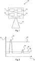
- FIG. 1 shows a block diagram of a radar level gauge 10 according to an embodiment of the invention.
- the radar level gauge can be configured in particular for determining a level of a medium, for example in a container, based on a transit time principle.
- the radar level gauge 10 has a control unit 11, a memory unit 14 and / or a memory device 14, a transmitting unit 12, a receiving unit 13 and an antenna 15.
- the transmitting unit 12 and the receiving unit 13 can also be combined to form a transceiver unit 12, 13.
- a transmission signal can be emitted in the direction of the medium, wherein a part of the transmission signal is reflected on the surface of the medium and can be received as a received signal via the antenna 15.
- the received signal can optionally be filtered by means of at least one filter and / or amplified by means of at least one amplifier.
- the optionally filtered and / or amplified received signal can then be sampled by means of an A / D converter and evaluated as a digital measurement signal which correlates with the received signal.
- control unit 11 is configured to communicate with the transmitting unit 12 and / or the receiving unit 13.
- control unit 11 can vary, change and / or adapt a transmission power and / or a transmission level of the transmission signal.
- control unit 11 may be configured to query a current transmission power from the transmitting unit 12.
- the transmission power and / or the transmission level can be described and / or specified via an absolute, relative or percentage value.
- the control unit 11 can thus receive the information that, for example, the transmission signal is currently transmitted with 80% of the maximum possible transmission power.
- control unit 11 is configured to determine the transmission power. Furthermore, the control unit 11 is set up to determine, adapt, calculate, vary and / or change a value of at least one evaluation parameter based on the determined transmission power.
- the value of the at least one evaluation parameter may be a threshold value at which, if it is exceeded and / or undershot, a part of the measurement signal, for example a peak, is detected and / or evaluated by the control unit 11 as a reflection from the surface of the medium. Based on the varied value of the at least one evaluation parameter, the fill level of the medium can thus be reliably determined taking into account the transmission power.
- the value of the at least one evaluation parameter may be stored in the memory device 14, for example.
- control unit 11 may be configured to determine the fill level based on the received signal and / or the measurement signal and based on a plurality of evaluation parameters.
- a parameter set of evaluation parameters can be stored in the memory unit 14, which and / or their values can represent a false signal suppression, as in FIG FIGS. 3 and 4 described in detail.
- the Störsignalausblendung may include about an impurity profile and / or a container empty profile.
- the control unit 11 is set up to vary, change, calculate and / or adjust values of the false signal blanking and / or values of the parameter set of the false signal blanking based on the determined transmit power.
- a precision of the level detection can be increased with adaptive transmission level in an advantageous manner.
- the Störsignalausblendung and / or values of Störsignalausblendung can be determined in the context of at least one reference measurement with the radar level gauge 10 at a known level, preferably with an empty container, with known transmission power. Another false signal suppression and / or values of another Noise suppression can be determined in the context of a further reference measurement at a further transmission power, which may differ from the transmission power of the previous reference measurement. Based on an interpolation and / or extrapolation then values of Störsignalausblendung can be adapted to the current transmission power. The same method can also be used for an evaluation parameter which is present as a threshold value and / or for any other evaluation parameter.
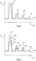
- FIG. 2 1 illustrates a measurement signal 30 determined using a radar fill level measuring device 10 according to the invention.
- the measurement signal 30 may be a digital representation of the received signal, a so-called echo curve 30, as in the control unit 11 and / or in the memory device 14 of the radar level gauge 10 the A / D conversion can be present.
- the x-axis 22 in this case represents a time axis 22, ie a signal propagation time of the transmit and / or receive signal, and the y-axis 21 represents a signal strength 21 and / or amplitude 21 of the measurement signal 30.
- the time axis 21 correlates with a distance the level measuring device 10.
- the measurement signal 30 has a first reflection 31, which may be caused for example by reflection of a portion of the transmission signal to the antenna 15 of the radar level gauge 10, and a second reflection 32, which by a reflection 32 of the transmission signal at the Surface of the medium may be caused.
- a threshold value 23 is shown, which is a value of an evaluation parameter.
- the control unit 11 is configured to recognize and / or evaluate the second reflection 32, which occurs after the first reflection 31 of the antenna 15 as reflection 32 on the product surface, when the amplitude 21 of the second reflection 32 exceeds the threshold value 23 .
- the defined threshold 23 may correspond approximately to a threshold at maximum transmission power of the radar level gauge 10.
- the transmission signal in the in FIG. 2 example shown has been sent with reduced transmission power, so that the resulting reflection 32 of the measurement signal 30 on the product surface does not reach and / or exceed the threshold value 23. Thus, the reflection 32 of the level would not be recognized as a level.
- the control unit 11 is therefore set up to determine a current transmission power and to adjust, change and / or vary the threshold value 23 based on the determined transmission power. Based on the determined transmission power, the control unit 11 can reduce the threshold value 23 to a lower threshold value 24, so that the reflection 32 exceeds the adapted threshold value 24 and can be determined as a reflection 32 on the product surface.
- the threshold value 24 can be calculated by the control unit 11 based on the current transmission power, a formula, a model and / or a characteristic field and / or stored in the memory device 14.
- the measurement signal 30 and / or the received signal can be increased by the control unit 11 based on the current transmission power, so that the reflection 32 reaches and / or exceeds the threshold value 23 and is thus detected as reflection 32 of the product surface.
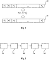
- FIG. 3 illustrates a determined with a radar level measurement device 10 according to the invention measuring signal 30 with a Störsignalausblendung 25.
- the measurement signal 30 may be a digital representation of the received signal, ie an echo curve 30, as may be present in the control unit 11 and / or in the storage device 14 of the radar level gauge 10 after the A / D conversion.
- the x-axis 22 in this case represents a time axis 22, ie a signal propagation time of the transmit and / or receive signal, and the y-axis 21 represents a signal strength 21 and / or amplitude 21 of the measurement signal 30.
- the time axis 21 correlates with a distance the Level gauge 10, so that based on the measurement signal 30, the level can be determined.
- the Störsignalausblendung 25 may include about an impurity profile and / or a container empty profile.
- the Störsignalausblendung 25 for this purpose have a parameter set of evaluation parameters, which can be stored in the memory unit 14.
- the evaluation parameters of the interference signal blanking may each correspond to a respective time interval, and the values of the respective evaluation parameters may correspond to an amplitude and / or a signal strength of the measurement signal 30 in this time interval.
- the Störsignalausblendung 25 can thus form a curve 25, with which the measurement signal 30 can be compared to determine the level.
- FIG. 3 is a reflection 31 of the antenna 15 and a Störreflexion 33 shown, which may be caused by container installations.
- a reflection 32 shown on the product surface which can be identified by the Störsignalausblendung 25.
- the control unit 11 may be configured to discard the reflections 31 and 33 if they do not exceed the values of the interference suppression 25.
- the control unit 11 can be configured to identify the reflection 32 as reflection 32 originating from the product surface, when the reflection 32 exceeds the values of the false signal suppression 25. In this way, the level can be reliably determined.
- the Störsignalausblendung 25 can be calculated approximately from the received measurement signal of a reference measurement, for example by means of a filter.
- a defined level preferably an empty container, the container and its reflections are measured.
- the transmission power of the radar level gauge 10 is known.
- FIG. 4 illustrates a variation, change and / or adaptation of the Störsignalausblendung 25 FIG. 3 by the control unit 11 of the radar level gauge depending on the transmission power of the transmission signal.
- Analogous to FIG. 3 show the individual peaks 31, 32, 33 in the measurement signal 30, which was determined based on a transmission signal with a first transmission power and / or a reception signal with a first reception power, a reflection 31 of the antenna 15, a reflection 33 on a faulty object and a reflection 32 on the product surface.
- FIG. 4 shows FIG. 4 a second measurement signal 30 ', which was determined based on a transmission signal with a second transmission power and / or a reception signal with a second reception power.
- the second transmission power is greater than the first transmission power, so that the amplitudes of the reflections 36, 37, 38 of the second measurement signal 30 'are each greater than the amplitudes of the reflections 31, 32, 33 of the first measurement signal 30.
- the reflections 36 and 38 of the second measurement signal 30 ' ie at the higher transmission power, exceed values of the interference signal suppression 25.
- the control unit 11 could thus identify the reflections 36, 38 as originating from the product surface.
- the control unit 11 is set up to determine the current transmit power, based for example on a query of the transmit power from the transmit unit 12.
- the control unit 11 can also specify the transmit power itself.
- the control unit 11 is furthermore set up to adjust and / or change values of the evaluation parameters, ie values of the false signal suppression 25, based on the determined transmission power.
- the control unit determines values of a further and / or current false signal suppression 26 in order to take into account and / or to take into account the increased transmission power.
- the control unit 11 or the evaluation electronics can adapt the interference signal suppression 25 to the varied transmission power of the radar level gauge 10, which leads to a calculated, current interference suppression 26.
- the received signal received by the reception unit and / or the measurement signal 30 correlating therewith can also be varied and / or adapted in accordance with the current transmission power.
- the measurement signal 30 ' may be scaled and / or shifted at the higher transmit power to provide the measurement signal 30, which may then be compared to the values of the noise blanking 25.
- the first interference suppression 25 can be determined, for example, when the container is empty and the transmission power is at a minimum.
- the calculated interference suppression 26 can be determined, for example, based on a known behavior, relationship and / or a formula between minimum and maximum transmission power. For example, there may be a certain amplitude difference in the measurement signal, such as a difference of 3dB, between minimum and maximum transmission power. If such parameters and / or such a behavior of the transmitting and receiving unit 12, 13 are known, for example by measurements and / or modeling of the circuit, an adapted Störsignalausblendung 26 can be calculated.
- values of the evaluation parameters for example based on a mathematical formula, a model and / or a characteristic field which can represent and / or indicate the relationship between the values of the evaluation parameters and the transmission power, can be determined with the current transmission power as the input variable for the current transmission power, as in FIG. 5 illustrated.
- the Störsignalausblendung 26 can be determined by a second reference measurement at a second transmission power.
- the first transmission power can correspond to a minimum transmission power
- the second transmission power can correspond to a maximum transmission power.
- the control unit 11 may then based on an interpolation and / or scaling between the values of the first interference suppression 25 and the values of the second interference suppression 26 determine values of interference suppression for a current transmission power.
- the interpolation may, for example, be linear, quadratic, logarithmic or exponential, in each case proportional or indirectly proportional to the transmission power.
- the control unit 11 may change the Störsignalausblendung by a shift and / or scaling.
- the determination of the Störsignalausblendung 25 can be done when commissioning the radar level gauge 10. This can be carried out automatically by the control unit 11 of the radar level gauge 10 and / or by a user input, such as by pressing a button and / or pressing an operating element of the level gauge 10, initiated. Further, the control unit 11 may be configured to periodically repeat the reference measurement of the false signal suppression, e.g. always when the container is empty or has a low level. In other words, a reaching and / or falling below a certain level, in particular a minimum level, trigger the reference measurement for the Störsignalausblendung and / or trigger.
- the interference suppression 25 or the interference signal suppression determined in this way can be stored or stored in a memory unit 14 of the radar level gauge 10.
- the Störsignalausblendung By determining the Störsignalausblendung at minimum and maximum transmission power can be responded to each transmit power accordingly, or the Störsignalausblendung can be varied accordingly, adapted or changed. If e.g. sent with only 50% of the maximum transmission power, so the noise false to be taken 26 can be calculated from the average of the first Störsmausausblendung 25 and the second Störsmausausblendung 26.
- the control unit 11 can take into account, for example by a map or a function, the values of the interference suppression at a first transmission power and / or a second transmission power into values of the Störsignalausblendung converted at the current transmission power.
- the current interference signal suppression can be generated from the at least one reference measurement and / or with the aid of a mathematical model or a formula.
- the function can also be a non-linear function.
- various functions depending on the environmental conditions, such as pressure, temperature, humidity and / or gas composition be deposited.
- the control unit 11 may also take into account other influencing variables such as pressure, temperature, humidity and / or gas composition in the container.
- FIG. 5 illustrates a variation of values of evaluation parameters by a radar level gauge 10 according to one embodiment of the invention.
- the values p 0 , p 1 , p 2 ,..., P n of the individual evaluation parameters can all be varied with the same function f or at least parts of the evaluation parameters with different functions, so that the variation and / or the relative difference between, for example p 0 to p ' 0 and p 1 to p' 1 does not necessarily have to be identical.
- the function may also depend on other variables, such as temperature, humidity, pressure and / or gas composition in the container.
- FIG. 6 is a flowchart illustrating steps of a method of operating a radar level gauge 10 according to one embodiment of the invention.
- the radar level gauge 10 may be a radar level gauge 10 as described in the preceding figures.
- a transmission signal in particular a radar transmission signal, is transmitted in the direction of the medium with the previously determined transmission power by the transmission unit 12.
- the emitted signal is reflected on the surface of the medium and received by the receiving unit 13 of the radar level gauge 10 in step S3.
- step S4 calculating, determining, changing, varying and / or adapting at least one value of an evaluation parameter and / or a measurement signal correlating with the received signal is performed based on the determined transmission power of the transmitting unit 12. Determining the fill level of the medium based on the received signal and / or based on the varied value of the at least one evaluation parameter takes place in step S5. This simplifies the evaluation of a measuring signal of a radar level gauge and improves the quality of the measurement.
- the radar level gauge can be put into operation in one step and it can be a measurement signal of the reference measurement, ie a Störsignalausblendung stored. Subsequently, a measuring cycle can be run through and the current transmission level can be determined. The transmission signal can be sent and the reception signal can be received. Values of the interference signal suppression and / or at least one threshold value can be calculated on the basis of the determined transmission power. The received signal can be converted into a digital measurement signal and with calculated values of the Noise suppression and / or compared with the at least one threshold. Subsequently, the fill level can be determined from the received measurement signal, the adjusted interference signal suppression and / or the threshold value.
- Level gauges may e.g. record the amplitudes of the reflections in the container.
- the amplitude of the reflection of the medium surface provides information about whether the level measuring device 10 detects the current measurement situation sufficiently accurately or whether the process conditions have deteriorated.
- the amplitude is e.g. Plotted over the location so as to obtain an amplitude profile of the reflection of the level in the whole tank with which then the amplitude of the reflection of the level of the current measurement can be compared.
- the transmission level should remain the same or, according to the invention, the amplitude of the reflection or the amplitude profile itself should be recalculated.
Landscapes
- Engineering & Computer Science (AREA)
- Physics & Mathematics (AREA)
- Radar, Positioning & Navigation (AREA)
- Remote Sensing (AREA)
- General Physics & Mathematics (AREA)
- Computer Networks & Wireless Communication (AREA)
- Electromagnetism (AREA)
- Fluid Mechanics (AREA)
- Thermal Sciences (AREA)
- Radar Systems Or Details Thereof (AREA)
- Measurement Of Levels Of Liquids Or Fluent Solid Materials (AREA)
Priority Applications (3)
| Application Number | Priority Date | Filing Date | Title |
|---|---|---|---|
| EP17183047.4A EP3435043B1 (fr) | 2017-07-25 | 2017-07-25 | Jauge radar, procédé et éléments de programme pour faire fonctionner un jauge radar |
| US16/014,217 US11231492B2 (en) | 2017-07-25 | 2018-06-21 | Radar fill level measurement device and method for operating a radar fill level measurement device |
| CN201810825677.7A CN109297564B (zh) | 2017-07-25 | 2018-07-25 | 雷达料位测量装置及雷达料位测量装置的操作方法 |
Applications Claiming Priority (1)
| Application Number | Priority Date | Filing Date | Title |
|---|---|---|---|
| EP17183047.4A EP3435043B1 (fr) | 2017-07-25 | 2017-07-25 | Jauge radar, procédé et éléments de programme pour faire fonctionner un jauge radar |
Publications (2)
| Publication Number | Publication Date |
|---|---|
| EP3435043A1 true EP3435043A1 (fr) | 2019-01-30 |
| EP3435043B1 EP3435043B1 (fr) | 2020-04-29 |
Family
ID=59399339
Family Applications (1)
| Application Number | Title | Priority Date | Filing Date |
|---|---|---|---|
| EP17183047.4A Active EP3435043B1 (fr) | 2017-07-25 | 2017-07-25 | Jauge radar, procédé et éléments de programme pour faire fonctionner un jauge radar |
Country Status (3)
| Country | Link |
|---|---|
| US (1) | US11231492B2 (fr) |
| EP (1) | EP3435043B1 (fr) |
| CN (1) | CN109297564B (fr) |
Cited By (3)
| Publication number | Priority date | Publication date | Assignee | Title |
|---|---|---|---|---|
| DE102019206531A1 (de) * | 2019-05-07 | 2020-11-12 | Vega Grieshaber Kg | Messgerät mit Selbsttestfunktion |
| DE102024109825A1 (de) * | 2024-04-09 | 2025-10-09 | Vega Grieshaber Kg | Radar-Messgerät |
| EP4682575A1 (fr) * | 2024-07-18 | 2026-01-21 | Robert Bosch GmbH | Procédé pour effectuer une détection d'objet dans un composant à l'aide d'un appareil de localisation |
Families Citing this family (8)
| Publication number | Priority date | Publication date | Assignee | Title |
|---|---|---|---|---|
| DE102018131604A1 (de) * | 2018-12-10 | 2020-06-10 | Endress+Hauser SE+Co. KG | Verfahren zur Füllstandsmessung |
| CN109799492B (zh) * | 2019-02-27 | 2020-12-15 | 珠海格力电器股份有限公司 | 一种调整微波雷达设备的输出功率的方法及装置 |
| CN109724672B (zh) * | 2019-03-01 | 2021-02-02 | 北京锐达仪表有限公司 | 电磁波料位开关的发射器及电磁波料位开关 |
| US11194032B2 (en) | 2019-03-22 | 2021-12-07 | Apple Inc. | Systems and methods for object detection by radio frequency systems |
| CN109959425B (zh) * | 2019-04-17 | 2021-10-12 | 北京锐达仪表有限公司 | 电磁波料位开关的处理方法及电磁波料位开关 |
| CN115151839A (zh) * | 2020-02-26 | 2022-10-04 | 华为技术有限公司 | 一种信号接收方法、设备、介质和雷达系统 |
| CN115485575A (zh) * | 2020-04-28 | 2022-12-16 | 维宁尔瑞典公司 | 雷达收发器测试 |
| DE102021115874A1 (de) * | 2021-06-18 | 2022-12-22 | Endress+Hauser SE+Co. KG | Füllstandsmessung |
Citations (4)
| Publication number | Priority date | Publication date | Assignee | Title |
|---|---|---|---|---|
| WO2003016835A1 (fr) * | 2001-07-27 | 2003-02-27 | Endress + Hauser Gmbh + Co. Kg | Procede pour evaluer les signaux de mesure d'un appareil de mesure fonctionnant selon le principe du temps de propagation |
| US20070101810A1 (en) * | 2005-11-09 | 2007-05-10 | Saab Rosemount Tank Radar Ab | Radar level gauge with variable transmission power |
| DE102006034554A1 (de) * | 2006-07-26 | 2008-01-31 | Vega Grieshaber Kg | Unabhängige Referenzpulserzeugung |
| DE102013109606A1 (de) * | 2013-09-03 | 2015-03-19 | Pepperl + Fuchs Gmbh | Verfahren zum Erfassen eines Füllstands in einem Sammelbehälter |
Family Cites Families (25)
| Publication number | Priority date | Publication date | Assignee | Title |
|---|---|---|---|---|
| US5508706A (en) * | 1991-09-30 | 1996-04-16 | Trw Inc. | Radar signal processor |
| DE4332071C2 (de) | 1993-09-21 | 1995-09-07 | Endress Hauser Gmbh Co | Verfahren zur Füllstandsmessung nach dem Radarprinzip |
| US6684696B2 (en) * | 2000-08-17 | 2004-02-03 | Vega Grieshaber, Kg | Filling-level measuring device that evaluates echo signals |
| US6684919B2 (en) * | 2001-02-08 | 2004-02-03 | Vega Grieshaber Kg | Filling level measuring device and method for the non-contact determination of the filling level of a filling product in a receptacle |
| DE10164030A1 (de) * | 2001-12-28 | 2003-07-17 | Grieshaber Vega Kg | Verfahren und Schaltungsanordnung zum Messen der Entfernung eines Gegenstandes |
| US7063604B2 (en) | 2004-03-05 | 2006-06-20 | Strasbaugh | Independent edge control for CMP carriers |
| DE102005057094B4 (de) * | 2005-11-30 | 2013-02-14 | Vega Grieshaber Kg | Füllstandradar mit variabler Sendeleistung |
| US7895889B2 (en) * | 2007-05-16 | 2011-03-01 | Rosemount Tank Radar Ab | Radar level gauge system with adaptive transmission power control |
| EP1992923B1 (fr) * | 2007-05-16 | 2012-07-11 | Rosemount Tank Radar AB | Système indicateur de niveau de radar avec contrôle de puissance de transmission adaptatif |
| US7541969B2 (en) * | 2007-05-31 | 2009-06-02 | Rosemount Tank Radar Ab | Radar level gauging system for use at sea |
| NL1034327C2 (nl) * | 2007-09-04 | 2009-03-05 | Enraf Bv | Werkwijze en inrichting voor het binnen een bepaald meetbereik vaststellen van het niveau L van een vloeistof met behulp van naar het vloeistofniveau uitgestraalde radarsignalen en door het vloeistofniveau gereflecteerde radarsignalen. |
| US8271212B2 (en) * | 2008-09-18 | 2012-09-18 | Enraf B.V. | Method for robust gauging accuracy for level gauges under mismatch and large opening effects in stillpipes and related apparatus |
| EP2226615B1 (fr) * | 2009-03-02 | 2018-08-22 | VEGA Grieshaber KG | Mesures de niveaux de remplissage à l'aide d'une évaluation d'une courbe d'écho |
| EP2366983B1 (fr) * | 2010-03-17 | 2020-04-29 | VEGA Grieshaber KG | Reconnaissance de mobilité dans un appareil de mesure de niveau |
| EP2372388A1 (fr) | 2010-04-01 | 2011-10-05 | Siemens Milltronics Process Instruments Inc. | Procédé de mesure de niveau par echos d'impulsions |
| EP2418465B1 (fr) * | 2010-07-19 | 2017-02-22 | VEGA Grieshaber KG | Profilage d'amplitude dans des appareils de mesure du niveau de remplissage |
| EP2527801B1 (fr) * | 2011-05-27 | 2019-12-11 | VEGA Grieshaber KG | Dispositif et procédé de détermination de caractéristiques de milieux et de récipients |
| DE102011079615A1 (de) * | 2011-07-22 | 2013-01-24 | Robert Bosch Gmbh | FMCW-Radarsystem und Interferenzerkennungsverfahren für FMCW-Radarsysteme |
| US8854253B2 (en) * | 2011-09-27 | 2014-10-07 | Rosemount Tank Radar Ab | Radar level gauging with detection of moving surface |
| US10389396B1 (en) * | 2011-11-17 | 2019-08-20 | Michael L. Gibbons | Terrain awareness and warning aircraft indicator equipment |
| US8554264B1 (en) * | 2011-11-17 | 2013-10-08 | Michael L. Gibbons | Systems and methods for optimizing broadcasts |
| US10257727B2 (en) * | 2013-03-15 | 2019-04-09 | DGS Global Systems, Inc. | Systems methods, and devices having databases and automated reports for electronic spectrum management |
| CN103885038B (zh) * | 2014-03-04 | 2016-06-15 | 上海无线电设备研究所 | 星载微波雷达系统功耗优化方法 |
| WO2015149850A1 (fr) * | 2014-04-02 | 2015-10-08 | Vega Grieshaber Kg | Correcteur pour le canal de fréquence intermédiaire d'un détecteur de niveau de remplissage fmcw |
| JP6880850B2 (ja) * | 2017-03-13 | 2021-06-02 | 富士通株式会社 | 測距装置,水位計測システム及び測距方法 |
-
2017
- 2017-07-25 EP EP17183047.4A patent/EP3435043B1/fr active Active
-
2018
- 2018-06-21 US US16/014,217 patent/US11231492B2/en active Active
- 2018-07-25 CN CN201810825677.7A patent/CN109297564B/zh active Active
Patent Citations (4)
| Publication number | Priority date | Publication date | Assignee | Title |
|---|---|---|---|---|
| WO2003016835A1 (fr) * | 2001-07-27 | 2003-02-27 | Endress + Hauser Gmbh + Co. Kg | Procede pour evaluer les signaux de mesure d'un appareil de mesure fonctionnant selon le principe du temps de propagation |
| US20070101810A1 (en) * | 2005-11-09 | 2007-05-10 | Saab Rosemount Tank Radar Ab | Radar level gauge with variable transmission power |
| DE102006034554A1 (de) * | 2006-07-26 | 2008-01-31 | Vega Grieshaber Kg | Unabhängige Referenzpulserzeugung |
| DE102013109606A1 (de) * | 2013-09-03 | 2015-03-19 | Pepperl + Fuchs Gmbh | Verfahren zum Erfassen eines Füllstands in einem Sammelbehälter |
Cited By (4)
| Publication number | Priority date | Publication date | Assignee | Title |
|---|---|---|---|---|
| DE102019206531A1 (de) * | 2019-05-07 | 2020-11-12 | Vega Grieshaber Kg | Messgerät mit Selbsttestfunktion |
| DE102024109825A1 (de) * | 2024-04-09 | 2025-10-09 | Vega Grieshaber Kg | Radar-Messgerät |
| EP4632425A1 (fr) * | 2024-04-09 | 2025-10-15 | VEGA Grieshaber KG | Appareil de mesure radar |
| EP4682575A1 (fr) * | 2024-07-18 | 2026-01-21 | Robert Bosch GmbH | Procédé pour effectuer une détection d'objet dans un composant à l'aide d'un appareil de localisation |
Also Published As
| Publication number | Publication date |
|---|---|
| CN109297564B (zh) | 2021-10-08 |
| CN109297564A (zh) | 2019-02-01 |
| US20190033116A1 (en) | 2019-01-31 |
| US11231492B2 (en) | 2022-01-25 |
| EP3435043B1 (fr) | 2020-04-29 |
Similar Documents
| Publication | Publication Date | Title |
|---|---|---|
| EP3435043B1 (fr) | Jauge radar, procédé et éléments de programme pour faire fonctionner un jauge radar | |
| EP2418465B1 (fr) | Profilage d'amplitude dans des appareils de mesure du niveau de remplissage | |
| EP2856086B1 (fr) | Procédé de mesure de niveau de remplissage d'après le principe du temps de vol | |
| DE4223346C2 (de) | Anordnung und Verfahren zur berührungslosen Füllstandmessung | |
| DE102006058852B4 (de) | Verfahren und Vorrichtung zur Korrektur nichtidealer Zwischenfrequenzsignale bei Abstandsmessgeräten nach dem FMCW-Prinzip | |
| EP2372319B1 (fr) | Accumulation d'écho parasite dans des bruits de récipients | |
| EP2759813B1 (fr) | Procédé et capteur de mesure du niveau de remplissage de supports stratifiés | |
| EP2634541A1 (fr) | Procédé de mesure de niveau de remplissage | |
| WO2014019948A1 (fr) | Procédé servant à déterminer et/ou à surveiller le niveau de remplissage d'un milieu dans un récipient | |
| WO2015018586A1 (fr) | Correction de la dispersion de radar fmcw dans un tube | |
| WO2008080840A1 (fr) | Procédé pour déterminer et surveiller le niveau d'un fluide dans un récipient selon un procédé de mesure du temps de propagation | |
| DE102009001010A1 (de) | Verfahren zur Ermittlung und Überwachung des Füllstands eines Mediums in einem Behälter nach einem Laufzeitmessverfahren | |
| DE102004055551A1 (de) | Verfahren zur Auswertung und Korrektur von Gesamtmesssignalen | |
| DE102014112228A1 (de) | Verfahren zur Vermeidung von Phasensprüngen | |
| EP3025128B1 (fr) | Procédé pour déterminer et surveiller le niveau d'un fluide dans un récipient selon un procédé de mesure du temps de propagation | |
| EP1839017B1 (fr) | Procede pour verifier le bon fonctionnement d'un dispositif de mesure de niveau de remplissage | |
| EP2626676A1 (fr) | Dispositif et procédé de correction d'un décalage | |
| EP3746753B1 (fr) | Procédé de détection d'états d'erreur potentiels sur un dispositif de mesure de remplissage à base de fmcw | |
| EP4628852A1 (fr) | Appareil de mesure de niveau de remplissage destiné à l'exécution d'une mesure | |
| WO2018127356A1 (fr) | Procédé permettant de détecter un état de défaillance d'un appareil de mesure de niveau de remplissage basé sur une onde continue modulée en fréquence | |
| EP4177578B1 (fr) | Procédé de mise en service d'un appareil de mesure de niveau de remplissage | |
| DE102024124753B4 (de) | Verfahren zur Zustandsüberwachung eines durch Laufzeitbestimmung elektromagnetischer Wellen arbeitenden Abstandssensors | |
| DE102022128703A1 (de) | Verfahren zum Betreiben einer Positionsmessvorrichtung | |
| WO2008116753A1 (fr) | Procédé de détermination de distance à l'aide de signaux acoustiques à modulation par impulsions | |
| DE102022132829A1 (de) | Messgerät mit Selbsttestfunktion |
Legal Events
| Date | Code | Title | Description |
|---|---|---|---|
| PUAI | Public reference made under article 153(3) epc to a published international application that has entered the european phase |
Free format text: ORIGINAL CODE: 0009012 |
|
| STAA | Information on the status of an ep patent application or granted ep patent |
Free format text: STATUS: REQUEST FOR EXAMINATION WAS MADE |
|
| 17P | Request for examination filed |
Effective date: 20181017 |
|
| AK | Designated contracting states |
Kind code of ref document: A1 Designated state(s): AL AT BE BG CH CY CZ DE DK EE ES FI FR GB GR HR HU IE IS IT LI LT LU LV MC MK MT NL NO PL PT RO RS SE SI SK SM TR |
|
| AX | Request for extension of the european patent |
Extension state: BA ME |
|
| RIC1 | Information provided on ipc code assigned before grant |
Ipc: G01F 25/00 20060101ALI20191023BHEP Ipc: G01S 13/88 20060101ALI20191023BHEP Ipc: G01F 23/288 20060101ALI20191023BHEP Ipc: G01S 7/292 20060101ALI20191023BHEP Ipc: G01F 23/292 20060101ALI20191023BHEP Ipc: G01F 23/296 20060101ALI20191023BHEP Ipc: G01F 23/284 20060101AFI20191023BHEP |
|
| GRAP | Despatch of communication of intention to grant a patent |
Free format text: ORIGINAL CODE: EPIDOSNIGR1 |
|
| STAA | Information on the status of an ep patent application or granted ep patent |
Free format text: STATUS: GRANT OF PATENT IS INTENDED |
|
| INTG | Intention to grant announced |
Effective date: 20191128 |
|
| GRAS | Grant fee paid |
Free format text: ORIGINAL CODE: EPIDOSNIGR3 |
|
| GRAA | (expected) grant |
Free format text: ORIGINAL CODE: 0009210 |
|
| STAA | Information on the status of an ep patent application or granted ep patent |
Free format text: STATUS: THE PATENT HAS BEEN GRANTED |
|
| AK | Designated contracting states |
Kind code of ref document: B1 Designated state(s): AL AT BE BG CH CY CZ DE DK EE ES FI FR GB GR HR HU IE IS IT LI LT LU LV MC MK MT NL NO PL PT RO RS SE SI SK SM TR |
|
| REG | Reference to a national code |
Ref country code: GB Ref legal event code: FG4D Free format text: NOT ENGLISH |
|
| REG | Reference to a national code |
Ref country code: CH Ref legal event code: EP |
|
| REG | Reference to a national code |
Ref country code: AT Ref legal event code: REF Ref document number: 1264005 Country of ref document: AT Kind code of ref document: T Effective date: 20200515 |
|
| REG | Reference to a national code |
Ref country code: DE Ref legal event code: R096 Ref document number: 502017004947 Country of ref document: DE |
|
| REG | Reference to a national code |
Ref country code: IE Ref legal event code: FG4D Free format text: LANGUAGE OF EP DOCUMENT: GERMAN |
|
| REG | Reference to a national code |
Ref country code: NL Ref legal event code: MP Effective date: 20200429 |
|
| REG | Reference to a national code |
Ref country code: LT Ref legal event code: MG4D |
|
| PG25 | Lapsed in a contracting state [announced via postgrant information from national office to epo] |
Ref country code: PT Free format text: LAPSE BECAUSE OF FAILURE TO SUBMIT A TRANSLATION OF THE DESCRIPTION OR TO PAY THE FEE WITHIN THE PRESCRIBED TIME-LIMIT Effective date: 20200831 Ref country code: GR Free format text: LAPSE BECAUSE OF FAILURE TO SUBMIT A TRANSLATION OF THE DESCRIPTION OR TO PAY THE FEE WITHIN THE PRESCRIBED TIME-LIMIT Effective date: 20200730 Ref country code: FI Free format text: LAPSE BECAUSE OF FAILURE TO SUBMIT A TRANSLATION OF THE DESCRIPTION OR TO PAY THE FEE WITHIN THE PRESCRIBED TIME-LIMIT Effective date: 20200429 Ref country code: IS Free format text: LAPSE BECAUSE OF FAILURE TO SUBMIT A TRANSLATION OF THE DESCRIPTION OR TO PAY THE FEE WITHIN THE PRESCRIBED TIME-LIMIT Effective date: 20200829 Ref country code: NO Free format text: LAPSE BECAUSE OF FAILURE TO SUBMIT A TRANSLATION OF THE DESCRIPTION OR TO PAY THE FEE WITHIN THE PRESCRIBED TIME-LIMIT Effective date: 20200729 Ref country code: SE Free format text: LAPSE BECAUSE OF FAILURE TO SUBMIT A TRANSLATION OF THE DESCRIPTION OR TO PAY THE FEE WITHIN THE PRESCRIBED TIME-LIMIT Effective date: 20200429 Ref country code: LT Free format text: LAPSE BECAUSE OF FAILURE TO SUBMIT A TRANSLATION OF THE DESCRIPTION OR TO PAY THE FEE WITHIN THE PRESCRIBED TIME-LIMIT Effective date: 20200429 |
|
| PG25 | Lapsed in a contracting state [announced via postgrant information from national office to epo] |
Ref country code: BG Free format text: LAPSE BECAUSE OF FAILURE TO SUBMIT A TRANSLATION OF THE DESCRIPTION OR TO PAY THE FEE WITHIN THE PRESCRIBED TIME-LIMIT Effective date: 20200729 Ref country code: LV Free format text: LAPSE BECAUSE OF FAILURE TO SUBMIT A TRANSLATION OF THE DESCRIPTION OR TO PAY THE FEE WITHIN THE PRESCRIBED TIME-LIMIT Effective date: 20200429 Ref country code: RS Free format text: LAPSE BECAUSE OF FAILURE TO SUBMIT A TRANSLATION OF THE DESCRIPTION OR TO PAY THE FEE WITHIN THE PRESCRIBED TIME-LIMIT Effective date: 20200429 Ref country code: HR Free format text: LAPSE BECAUSE OF FAILURE TO SUBMIT A TRANSLATION OF THE DESCRIPTION OR TO PAY THE FEE WITHIN THE PRESCRIBED TIME-LIMIT Effective date: 20200429 |
|
| PG25 | Lapsed in a contracting state [announced via postgrant information from national office to epo] |
Ref country code: NL Free format text: LAPSE BECAUSE OF FAILURE TO SUBMIT A TRANSLATION OF THE DESCRIPTION OR TO PAY THE FEE WITHIN THE PRESCRIBED TIME-LIMIT Effective date: 20200429 Ref country code: AL Free format text: LAPSE BECAUSE OF FAILURE TO SUBMIT A TRANSLATION OF THE DESCRIPTION OR TO PAY THE FEE WITHIN THE PRESCRIBED TIME-LIMIT Effective date: 20200429 |
|
| PG25 | Lapsed in a contracting state [announced via postgrant information from national office to epo] |
Ref country code: DK Free format text: LAPSE BECAUSE OF FAILURE TO SUBMIT A TRANSLATION OF THE DESCRIPTION OR TO PAY THE FEE WITHIN THE PRESCRIBED TIME-LIMIT Effective date: 20200429 Ref country code: SM Free format text: LAPSE BECAUSE OF FAILURE TO SUBMIT A TRANSLATION OF THE DESCRIPTION OR TO PAY THE FEE WITHIN THE PRESCRIBED TIME-LIMIT Effective date: 20200429 Ref country code: EE Free format text: LAPSE BECAUSE OF FAILURE TO SUBMIT A TRANSLATION OF THE DESCRIPTION OR TO PAY THE FEE WITHIN THE PRESCRIBED TIME-LIMIT Effective date: 20200429 Ref country code: IT Free format text: LAPSE BECAUSE OF FAILURE TO SUBMIT A TRANSLATION OF THE DESCRIPTION OR TO PAY THE FEE WITHIN THE PRESCRIBED TIME-LIMIT Effective date: 20200429 Ref country code: ES Free format text: LAPSE BECAUSE OF FAILURE TO SUBMIT A TRANSLATION OF THE DESCRIPTION OR TO PAY THE FEE WITHIN THE PRESCRIBED TIME-LIMIT Effective date: 20200429 Ref country code: RO Free format text: LAPSE BECAUSE OF FAILURE TO SUBMIT A TRANSLATION OF THE DESCRIPTION OR TO PAY THE FEE WITHIN THE PRESCRIBED TIME-LIMIT Effective date: 20200429 Ref country code: CZ Free format text: LAPSE BECAUSE OF FAILURE TO SUBMIT A TRANSLATION OF THE DESCRIPTION OR TO PAY THE FEE WITHIN THE PRESCRIBED TIME-LIMIT Effective date: 20200429 |
|
| REG | Reference to a national code |
Ref country code: DE Ref legal event code: R097 Ref document number: 502017004947 Country of ref document: DE |
|
| PG25 | Lapsed in a contracting state [announced via postgrant information from national office to epo] |
Ref country code: PL Free format text: LAPSE BECAUSE OF FAILURE TO SUBMIT A TRANSLATION OF THE DESCRIPTION OR TO PAY THE FEE WITHIN THE PRESCRIBED TIME-LIMIT Effective date: 20200429 Ref country code: SK Free format text: LAPSE BECAUSE OF FAILURE TO SUBMIT A TRANSLATION OF THE DESCRIPTION OR TO PAY THE FEE WITHIN THE PRESCRIBED TIME-LIMIT Effective date: 20200429 Ref country code: MC Free format text: LAPSE BECAUSE OF FAILURE TO SUBMIT A TRANSLATION OF THE DESCRIPTION OR TO PAY THE FEE WITHIN THE PRESCRIBED TIME-LIMIT Effective date: 20200429 |
|
| REG | Reference to a national code |
Ref country code: CH Ref legal event code: PL |
|
| PLBE | No opposition filed within time limit |
Free format text: ORIGINAL CODE: 0009261 |
|
| STAA | Information on the status of an ep patent application or granted ep patent |
Free format text: STATUS: NO OPPOSITION FILED WITHIN TIME LIMIT |
|
| 26N | No opposition filed |
Effective date: 20210201 |
|
| REG | Reference to a national code |
Ref country code: BE Ref legal event code: MM Effective date: 20200731 |
|
| PG25 | Lapsed in a contracting state [announced via postgrant information from national office to epo] |
Ref country code: CH Free format text: LAPSE BECAUSE OF NON-PAYMENT OF DUE FEES Effective date: 20200731 Ref country code: LI Free format text: LAPSE BECAUSE OF NON-PAYMENT OF DUE FEES Effective date: 20200731 Ref country code: LU Free format text: LAPSE BECAUSE OF NON-PAYMENT OF DUE FEES Effective date: 20200725 |
|
| PG25 | Lapsed in a contracting state [announced via postgrant information from national office to epo] |
Ref country code: SI Free format text: LAPSE BECAUSE OF FAILURE TO SUBMIT A TRANSLATION OF THE DESCRIPTION OR TO PAY THE FEE WITHIN THE PRESCRIBED TIME-LIMIT Effective date: 20200429 Ref country code: BE Free format text: LAPSE BECAUSE OF NON-PAYMENT OF DUE FEES Effective date: 20200731 |
|
| PG25 | Lapsed in a contracting state [announced via postgrant information from national office to epo] |
Ref country code: IE Free format text: LAPSE BECAUSE OF NON-PAYMENT OF DUE FEES Effective date: 20200725 |
|
| PG25 | Lapsed in a contracting state [announced via postgrant information from national office to epo] |
Ref country code: TR Free format text: LAPSE BECAUSE OF FAILURE TO SUBMIT A TRANSLATION OF THE DESCRIPTION OR TO PAY THE FEE WITHIN THE PRESCRIBED TIME-LIMIT Effective date: 20200429 Ref country code: MT Free format text: LAPSE BECAUSE OF FAILURE TO SUBMIT A TRANSLATION OF THE DESCRIPTION OR TO PAY THE FEE WITHIN THE PRESCRIBED TIME-LIMIT Effective date: 20200429 Ref country code: CY Free format text: LAPSE BECAUSE OF FAILURE TO SUBMIT A TRANSLATION OF THE DESCRIPTION OR TO PAY THE FEE WITHIN THE PRESCRIBED TIME-LIMIT Effective date: 20200429 |
|
| PG25 | Lapsed in a contracting state [announced via postgrant information from national office to epo] |
Ref country code: MK Free format text: LAPSE BECAUSE OF FAILURE TO SUBMIT A TRANSLATION OF THE DESCRIPTION OR TO PAY THE FEE WITHIN THE PRESCRIBED TIME-LIMIT Effective date: 20200429 |
|
| P01 | Opt-out of the competence of the unified patent court (upc) registered |
Effective date: 20230508 |
|
| REG | Reference to a national code |
Ref country code: AT Ref legal event code: MM01 Ref document number: 1264005 Country of ref document: AT Kind code of ref document: T Effective date: 20220725 |
|
| PG25 | Lapsed in a contracting state [announced via postgrant information from national office to epo] |
Ref country code: AT Free format text: LAPSE BECAUSE OF NON-PAYMENT OF DUE FEES Effective date: 20220725 |
|
| PGFP | Annual fee paid to national office [announced via postgrant information from national office to epo] |
Ref country code: DE Payment date: 20250722 Year of fee payment: 9 |
|
| PGFP | Annual fee paid to national office [announced via postgrant information from national office to epo] |
Ref country code: GB Payment date: 20250724 Year of fee payment: 9 |
|
| PGFP | Annual fee paid to national office [announced via postgrant information from national office to epo] |
Ref country code: FR Payment date: 20250723 Year of fee payment: 9 |