EP3435362B1 - Système d'affichage comportant un module d'affichage par elements mobiles autour de liaisons flexibles, et piece d'horlogerie comportant un tel système d'affichage - Google Patents
Système d'affichage comportant un module d'affichage par elements mobiles autour de liaisons flexibles, et piece d'horlogerie comportant un tel système d'affichage Download PDFInfo
- Publication number
- EP3435362B1 EP3435362B1 EP18184006.7A EP18184006A EP3435362B1 EP 3435362 B1 EP3435362 B1 EP 3435362B1 EP 18184006 A EP18184006 A EP 18184006A EP 3435362 B1 EP3435362 B1 EP 3435362B1
- Authority
- EP
- European Patent Office
- Prior art keywords
- display
- display module
- display system
- actuator
- rotation
- Prior art date
- Legal status (The legal status is an assumption and is not a legal conclusion. Google has not performed a legal analysis and makes no representation as to the accuracy of the status listed.)
- Active
Links
Images


Classifications
-
- G—PHYSICS
- G04—HOROLOGY
- G04B—MECHANICALLY-DRIVEN CLOCKS OR WATCHES; MECHANICAL PARTS OF CLOCKS OR WATCHES IN GENERAL; TIME PIECES USING THE POSITION OF THE SUN, MOON OR STARS
- G04B19/00—Indicating the time by visual means
-
- G—PHYSICS
- G04—HOROLOGY
- G04B—MECHANICALLY-DRIVEN CLOCKS OR WATCHES; MECHANICAL PARTS OF CLOCKS OR WATCHES IN GENERAL; TIME PIECES USING THE POSITION OF THE SUN, MOON OR STARS
- G04B19/00—Indicating the time by visual means
- G04B19/06—Dials
- G04B19/065—Dials with several parts
-
- G—PHYSICS
- G04—HOROLOGY
- G04B—MECHANICALLY-DRIVEN CLOCKS OR WATCHES; MECHANICAL PARTS OF CLOCKS OR WATCHES IN GENERAL; TIME PIECES USING THE POSITION OF THE SUN, MOON OR STARS
- G04B19/00—Indicating the time by visual means
- G04B19/06—Dials
- G04B19/10—Ornamental shape of the graduations or the surface of the dial; Attachment of the graduations to the dial
- G04B19/106—Special number markings
-
- G—PHYSICS
- G04—HOROLOGY
- G04B—MECHANICALLY-DRIVEN CLOCKS OR WATCHES; MECHANICAL PARTS OF CLOCKS OR WATCHES IN GENERAL; TIME PIECES USING THE POSITION OF THE SUN, MOON OR STARS
- G04B19/00—Indicating the time by visual means
- G04B19/06—Dials
- G04B19/16—Shiftable dials, e.g. indicating alternately from 1 to 12 and from 13 to 24
- G04B19/166—Shiftable dials, e.g. indicating alternately from 1 to 12 and from 13 to 24 with rotating scales
-
- G—PHYSICS
- G04—HOROLOGY
- G04B—MECHANICALLY-DRIVEN CLOCKS OR WATCHES; MECHANICAL PARTS OF CLOCKS OR WATCHES IN GENERAL; TIME PIECES USING THE POSITION OF THE SUN, MOON OR STARS
- G04B45/00—Time pieces of which the indicating means or cases provoke special effects, e.g. aesthetic effects
- G04B45/0023—Inscriptions or pictures moved by the clockwork, e.g. for advertising
-
- G—PHYSICS
- G04—HOROLOGY
- G04B—MECHANICALLY-DRIVEN CLOCKS OR WATCHES; MECHANICAL PARTS OF CLOCKS OR WATCHES IN GENERAL; TIME PIECES USING THE POSITION OF THE SUN, MOON OR STARS
- G04B45/00—Time pieces of which the indicating means or cases provoke special effects, e.g. aesthetic effects
- G04B45/0038—Figures or parts thereof moved by the clockwork
- G04B45/0061—Moving parts of the clockwork, e.g. pendulum, hands in special form, mostly constructed as a figure
-
- G—PHYSICS
- G09—EDUCATION; CRYPTOGRAPHY; DISPLAY; ADVERTISING; SEALS
- G09F—DISPLAYING; ADVERTISING; SIGNS; LABELS OR NAME-PLATES; SEALS
- G09F9/00—Indicating arrangements for variable information in which the information is built-up on a support by selection or combination of individual elements
- G09F9/30—Indicating arrangements for variable information in which the information is built-up on a support by selection or combination of individual elements in which the desired character or characters are formed by combining individual elements
- G09F9/302—Indicating arrangements for variable information in which the information is built-up on a support by selection or combination of individual elements in which the desired character or characters are formed by combining individual elements characterised by the form or geometrical disposition of the individual elements
-
- G—PHYSICS
- G09—EDUCATION; CRYPTOGRAPHY; DISPLAY; ADVERTISING; SEALS
- G09F—DISPLAYING; ADVERTISING; SIGNS; LABELS OR NAME-PLATES; SEALS
- G09F9/00—Indicating arrangements for variable information in which the information is built-up on a support by selection or combination of individual elements
- G09F9/30—Indicating arrangements for variable information in which the information is built-up on a support by selection or combination of individual elements in which the desired character or characters are formed by combining individual elements
- G09F9/37—Indicating arrangements for variable information in which the information is built-up on a support by selection or combination of individual elements in which the desired character or characters are formed by combining individual elements being movable elements
Definitions
- the invention relates to the general field of microtechnology and in particular to the manufacture of parts by etching of silicon.
- the invention relates more particularly to a display system comprising a mechanical display module comprising a plurality of movable elements relative to one another around at least one deformable connection of the flexible blade type.
- the invention also relates to a timepiece comprising such a display system.
- the display module and the display device of the invention find a particular application in the watchmaking industry, in particular for producing dials for watches or animated clocks.
- Analogue display systems in particular with hands, have been known and have been used for decades in a multitude of applications in order to provide a direct indication, for example on a graduated scale, a dial or other system for representing a value of. measurement of a physical quantity such as speed, temperature, pressure, intensity, voltage or electrical resistance, of any information, or even, and probably the most widespread, for the measurement of time.
- the needles of a display device consist of a rigid unitary body secured to an axis of rotation mu by a movement, for example a watch movement in the case of a timepiece.
- the needle performs a corresponding rotation, at least one of its free ends describing a trajectory of circular section thus pointing in each of its positions on the circular trajectory a value indication information item.
- the indication is thus produced essentially in the longitudinal axis of the needle at the level of one and / or the other of its opposite ends in collaboration where appropriate with an underlying display, such as a scale by example.
- Mechanical display systems are also known, in particular for clocks, for example with pallets, which indicate time information by aligning numbers printed on the pallets, the latter being pivoted about an axis by gravity during release. of blocking bolts at each date of time to be indicated.
- the display mechanism described in the request WO2006024311 is based on a series of many cogwheels.
- display devices with a simple unitary structure and allowing direct display of an item of information or a pattern, in particular a date of time, where appropriate without associated hands, with a capacity, are not known to date.
- An object of the invention is to provide a display system comprising an animated display module, in particular for timepieces, comprising movable elements around deformable links of the flexible blade or pivot type, more particularly for the mechanical display of a current time calendar, and an actuation device that is simple to implement.
- the present invention proposes an alternative method of presenting the hours and minutes by animating the 3D patterns sequentially forming the different values of time.
- Another object of the invention is to provide such a display system, the actuating device of which does not require modification of a basic watch movement but which can kinematically link to one or more moving parts of the finishing gear train. - here directly or indirectly.
- a particular application of the invention consists in the production of animated watch faces mechanically displaying selectively the current hours and minutes in digital or other form.
- Another object of the invention is to provide a timepiece provided with such a display system.
- said at least one actuator of each display module is integral with the frame and movable relative to the latter by means of a plurality of flexible connections.
- said actuator extends in a direction radial with respect to the geometric center (C).
- the actuating device is rotatable about an axis of rotation passing through the geometric center (C).
- the actuating device is arranged to exert in at least one angular position around the axis of rotation a force capable of mobilizing the actuator of each display module so as to move said members of mobile display from the rest position to the display position to simultaneously form a said pattern on each display module.
- the actuating device comprises first and second actuating wheels arranged to be mobile in rotation around the axis of rotation so as to cooperate and mobilize in at least one angular position around the axis of rotate the actuator of each display module.
- the first and second actuating wheels comprise a cam or a lug.
- the first and second actuator wheels are indexed in rotation with respect to one another around the axis of rotation.
- the first and second actuating wheels are indexed in rotation with respect to each other about the axis of rotation so that the patterns simultaneously formed on each display module are aligned in the same radial direction from the geometric center (C).
- the actuating device comprises a single actuating mobile arranged to cooperate simultaneously in rotation with the actuator of each display module.
- a display module is arranged to be movable in rotation about the axis of rotation with reference to the other display movable and indexed in rotation with respect to said movable. actuation such that the patterns are simultaneously formed on each display module are aligned in the same radial direction from the geometric center (C).
- the at least two display members are integral and movable relative to the frame around a flexible connection at least between said rest position and said display position.
- the at least two display members comprise a display portion of a said pattern complementary to a display portion of another display member of the same module. display at least to form said pattern in at least one relative position of said display members.
- each said display module forms a monolithic part comprising said display members, the frame, the actuator and one or more deformable links connecting said display members and said actuator to the frame.
- each display module comprises n display members, n being an integer greater than 1, at least one display member being integral with the frame and stationary with respect to the latter.
- the display system comprises a first and a second circular dial superimposed and concentric with respect to the geometric center, each dial comprising m said display modules, m being an integer, juxtaposed to each other around the actuating device concentrically at the geometric center such that the latter cooperates simultaneously, in a given angular position around the center with an actuating button of a first and a second display module of each said dial.
- the number m of display modules for each of the dials is between 4 and 24, preferably between 12 and 24.
- each said circular dial preferably forms a monolithic part, in particular of mono- or polycrystalline silicon, comprising said m display modules integral with one another obtained by deep engraving processes.
- Such an embodiment allows in particular an incalculable number of aesthetic variations of the dial while making it possible to produce very precisely each of the functional parts of each of the display modules, in particular the display members, the frame, the actuator as well as the flexible connections. between the frame and the display members and the actuator in particular.
- the flexible links are for example made up of flexible blades with a width between 2 and 50 microns, the thickness of the frame and of the display member (s) being greater than 30 microns. This dimensioning thus effectively provides an elastic character to the flexible blades forming the flexible links while the portions of greater thickness of the frame and of the display members are completely rigid and devoid of elastic nature.
- the present invention also relates to a timepiece comprising a display system as described above.
- the actuating device is kinematically linked to the hours mobile and to the minutes mobile or the roadway of the finishing gear of a watch movement.
- the pattern of each said display module is configured to display a date of time.
- the display system of the invention makes it possible in particular to operate a simultaneous display of the hours and minutes per 5-minute segment by superimposing two cams linked respectively to the barrel of the hours moving body and to the floor of the finishing gear, respectively centered on the geometric center of two dials comprising display modules configured to digitally display the hours for a first dial, the second dial superimposed and concentric with the first allowing it to display the minutes.
- the actuating device is linked only to the hours mobile and at least one display module is kinematically linked to the minutes mobile of the finishing train of the watch movement.
- the present invention relates to an analog display system comprising display modules animated by means of a mechanical actuation device, in particular but not exclusively for the display of time information in a room. watchmaking, as shown and described below in figures 1 to 6 .
- the invention also relates to a timepiece comprising such a display system.
- a preferred application of the invention relates to the field of watchmaking, it is not limited to a display of time information and can also be implemented in any field requiring the use of a system. display of any information or representation in an animated form.
- such a display module 1 consists of a display module of a pattern M such as a figure or a number comprising a fixed frame 2 of which at least two display members are secured, in the species three display bodies 31, 32, 33 to form the number "6" ( figure 1B ).
- the display members 31, 32, 33 are integral with the frame 2 and each comprise a display portion 31a, 32a, 33a of the pattern M, said display portions being complementary to one another so that they form said pattern in at least one relative position of said display members 31, 32, 33.
- the display members 31, 32, 33 are integral with the frame 2 and the members 32, 33 are also movable relative to the frame 2 by means of at least one flexible link 4 formed by at least one blade flexible 41 between a first rest position, shown in figure 1A , in which the display portions of the display members 31, 32, 33 are distant from each other and a display position, shown in figure 1B , wherein said display portions 31a, 32a, 33a are counter-affixed to each other to form and display the pattern M, in this case a number "6".
- the movement of the display members 32, 33 relative to the frame 2 around their flexible connection 4 between the rest and display positions advantageously results according to the invention from the cooperation of said display members 32, 33 with a push button 'actuation 5 arranged relative to the frame 2 and to the display members to transmit a force capable of inducing a movement of said display members by elastic deformation around flexible connections 4 also following the action of an actuating device 6 distinct from the display module 1, such as a cam 61 movable in rotation about an axis A on the figures 1A and 1B , on the actuating button 5.
- an actuating device 6 distinct from the display module 1, such as a cam 61 movable in rotation about an axis A on the figures 1A and 1B , on the actuating button 5.
- the display module 1 of the invention is advantageously made of a monolithic part formed of a rigid material, which is understood in the context of the present invention as any material whose Young's modulus is greater than 2.3 GPa .
- a preferred material for making the display module 1 of the invention is silicon, monocrystalline or polycrystalline, from which it is easily possible, for example by deep etching processes (in particular DRIE - for Deep Reactive-ion Etching in English), form the frame 2 and the display members 31, 32, 33 connected to each other by at least one flexible connection 4, resulting in particular advantageously from the formation during the deep etching process of one or more flexible blades 4 with a width of between 2 and 50 microns, the thickness of the frame 2 and of the display member (s) preferably being greater than 30 microns.
- the movable display members 32, 33 and their display portions 32a, 33a are connected directly to the actuating button 5.
- the display member 31 remains identical to that of the figures 1A and 1B .
- This embodiment has the particularity of not presenting any interruption in the movement control chain, from the actuating button 5 to the display portions 32a, 33a. There is no friction within the display module 1 due to movements, only deformations, therefore a minimum loss of energy.
- the display portions 32a, 33b are connected to the upper ends of two rockers 32b and 33b, rotating around flexible links 4 in the form of flexible "butterfly" pivots 42 integral with the frame 2.
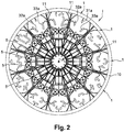
- the structural and functional principles of the display module 1 of figures 1A and 1B can be extended to produce an animated circular dial I comprising a plurality of display modules 1 as shown in figure 2 .
- Such a dial can be implemented in a timepiece such as a watch or a clock for displaying the time in animated form with a device 6 for actuating push-buttons 5 arranged to be able to rotate in the center.
- a timepiece such as a watch or a clock
- a device 6 for actuating push-buttons 5 arranged to be able to rotate in the center.
- of the dial and of the display modules 1 is kinematically connected to the hour wheel of a watch movement of the timepiece.
- the actuating device 6 is represented by a ring bearing on its periphery a protuberance forming a cam 61.
- the cam 61 pushes the free end of the actuating button 5 ( figure 1B ) which acts as a follower contact, and causes a translational movement of the actuating pusher 5 which then pushes on the intermediate levers 32b, 33b which pivot relative to the frame 2 and thus cause the displacement of the display portions 32a, 33a to the display position in which said display portions fit with portion 31a to form the pattern "6" on the figure 1B .
- An animated display system comprising display portions which are movable according to a determined period in order to generate a visual animation effect within the display.
- CH01143 / 16 by providing a display system 100 consisting of the assembly of at least two display modules 1, 1 'and preferably two dials I1, I2 as shown schematically in figures 3 and 5 , each dial each comprising 12 display modules 1, 1 'arranged concentrically in a monolithic part forming the dial I1, I2 around a geometric center C through which passes an axis of rotation A of an actuator 6 comprising one or two cams 61, 62 as described below with reference to figures 4 and 6 .
- Each of the display modules 1, 1 'thus forms a quarter or time display sector of the dials I1, I2.
- Each dial I1, I2 consists of a circular frame 10, 20 incorporating radial beams 11, 21 which support the modules of displays 1, 1 'set in motion by the movement of actuating buttons 5, 5' present in each of the time quarters.
- the first dial I1 is intended to display the hours sequentially in each of the hourly quarters as a function of the displayed value.
- the dial I1 is preferably, in use in a timepiece, fixed to the frame B of the timepiece, for example by means of an extension of the radial beams 11.
- the actuation pusher 5 is set. in motion by the rotational action of a first cam 61 of the actuating device 6, in kinematic connection to the hours wheel H of the finishing gear of a watch movement and which comes into contact with the actuating button 5.
- the second dial I2 is intended to display the minutes, in increments of five minutes for example.
- This dial I2 is not located in the same plane as the dial I1 but is advantageously superimposed on it coaxially with the axis A.
- the dial I2 is located on the dial I1 and the minute digit is displayed on a diameter different from the hour display diameter so as not to disturb the reading of these different values.
- the dial I2 is also like the dial I1 fixed to the frame B of the timepiece, for example by means of an extension of the radial beams 21.
- the actuating device 6 comprises two cams 61 and 62 cooperating respectively with the actuator button 5 of the dial I1 to display the hours in the display modules 1 of this dial I1 and with the actuator pushbutton 5 'of the dial I2 to display the minutes in the display modules 1' of the dial I2 .
- the cam 61 is advantageously integral with a barrel fixed to the hours wheel H of the finishing gear train of the movement of the timepiece, while the cam 62 is itself secured to the roadway Mi of the same finishing gear. We thus obtain an advantage of hours and minutes as shown on the figure 3 , with hours and minutes offset on two different diameters.
- the dial I2 is this time mounted to rotate around the axis A of rotation of the actuator, fixed on a rotating peripheral element, a disc or as shown here a ring 22, for example by means of an extension of the radial beams 21.
- the ring 22 is advantageously arranged in kinematic connection, by any means known to those skilled in the art of watchmaking, with the minute wheel of the finishing gear of the watch movement, which prints on the ring 22 and on the dial I2 which is integral with it, a speed of rotation approximately 12 times greater than the speed of rotation of a single cam 61, integral with the barrel of the hour wheel H.
- a hole 30 present in the barrel of the hour wheel H essentially due to the absence of the minutes pavement and the seconds axis, releases a passage allowing, if necessary, to draw kinematic links between the watch movement, located under the display system 100, and a space 50 located above the display system 100 in order to provide additional functions, such as a needle dial.
- This space can also accommodate part of the watch movement, for example the time regulating organ (anchor, escape wheel, ...), This space could accommodate a tourbillon performing a rotation in five minutes by driving an index pointing on a dial graduated from 1 to 4, creating a secondary minute display.
- the first and the second display module 1, 1 ' are arranged concentrically with respect to each other around a common geometric center C, the distance from the first display module 1 from the common geometric center C being different from the distance of the second display module 1 'from the common geometric center C.
- the first and the second a display module 1, 1' are placed on two arcs of circles or on two circumferences having a common geometric center C but different radii.
- first and second mobile actuators 61, 62 comprise a cam 61 or a lug.
- each display module 1, 1 ′ consists of monocrystalline or polycrystalline silicon.
- the actuating device is movable in rotation about an axis of rotation A passing through the geometric center C.
- the actuating device 6 is arranged to exert in at least one angular position around the axis of rotation A a force capable of mobilizing the actuator 5, 5 'of each display module 1, 1' so as to move said movable display members 32, 33; 32 ', 33' from the rest position to the display position to simultaneously form a said pattern M, M 'on each display module 1, 1'.
- the at least two display members 32, 33; 32 ', 33' are integral and movable relative to the frame 2, 2 'around a link flexible 4, at least between said rest position and said display position.
- each display module comprises n display members 31, 32, 33; 31 ', 32', 33 ', n being an integer greater than 1, at least one display member 31, 31' being integral with the frame and stationary relative to the latter.
- the actuating device 6 is kinematically linked to the hours mobile and at least one display module is kinematically linked to the minutes mobile of a watch movement, the pattern M, M 'of each said module. display being configured to display a date of time.
Landscapes
- Physics & Mathematics (AREA)
- General Physics & Mathematics (AREA)
- Engineering & Computer Science (AREA)
- Theoretical Computer Science (AREA)
- Electromechanical Clocks (AREA)
Description
- L'invention concerne le domaine général de la microtechnique et notamment la fabrication de pièces par gravure de silicium. L'invention concerne plus particulièrement un système d'affichage comportant un module d'affichage mécanique comportant une pluralité d'éléments mobiles relativement les uns aux autres autour d'au moins une liaison déformable de type lame flexible.
- L'invention concerne également une pièce d'horlogerie comportant un tel système d'affichage.
- Le module d'affichage et le dispositif d'affichage de l'invention trouvent une application particulière dans l'industrie horlogère, notamment pour la réalisation de cadrans de montres ou horloges animés.
- Les systèmes d'affichages analogiques, notamment à aiguilles, sont connus et utilisés depuis des décennies dans une multitude d'applications afin de procurer une indication directe, par exemple sur une échelle graduée, un cadran ou autre système de représentation d'une valeur de mesure d'une grandeur physique telle que vitesse, température, pression, intensité, tension ou résistance électrique, d'une information quelconque, ou encore, et de manière probablement la plus répandue pour la mesure du temps.
- Dans une grande majorité de cas, les aiguilles d'un dispositif d'affichage sont constituées d'un corps unitaire rigide solidaire d'un axe de rotation mu par un mouvement, par exemple un mouvement horloger dans le cas d'une pièce d'horlogerie. A chaque pas de rotation de l'axe de rotation l'aiguille effectue une rotation correspondante, une au moins de ses extrémités libres décrivant une trajectoire de section circulaire pointant ainsi en chacune de ses positions sur la trajectoire circulaire une information d'indication de valeur physique mesurée, d'un quantième de temps, ou de façon générale de toute information à indiquer à un utilisateur. L'indication est ainsi réalisée essentiellement dans l'axe longitudinal de l'aiguille au niveau d'une et/ou de l'autre de ses extrémités opposés en collaboration le cas échéant avec un affichage sous-jacent, telle qu'une échelle par exemple.
- On connait également, notamment pour des horloges, des systèmes d'affichage mécaniques, par exemple à palettes, qui indiquent une information horaire par alignement de chiffres imprimés sur les palettes, ces dernières étant pivotées autour d'un axe par gravité lors de la libération de verrous de blocage à chaque quantième de temps à indiquer.
- D'autres variantes d'affichages actionnés par des systèmes mécaniques ont également été proposées dans l'état de la technique, essentiellement dans le domaine horloger. On peut citer entre autres l'affichage numérique de type « planche à clous » du modèle « Opus 8 », commercialisé par la société Harry Winston SA ou encore le dispositif d'affichage numérique de l'heure en cours par rotation d'un disque sous-jacent à un cadran doté d'un guichet tel que proposé dans la demande de brevet suisse
CH 691833 A5 - Certaines propositions reposent essentiellement sur l'utilisation d'un cadran secondaire, de disques rotatifs comportant un index pointant sur des chiffres des minutes (
EP2439600A1 ), ou de disques comportant les valeurs des minutes qui s'affichent séquentiellement en suivant l'aiguille des heures (EP2977831A1 ;US2017108832A1 ). - Alternativement d'autres propositions consistent à utiliser un empilement de disques transparents pour combiner les motifs qu'ils comportent afin de créer un affichage animé (
US2003099159A1 ). - Enfin, il existe également des affichages faisant appel à de grandes complications mécaniques, par exemple en animant une multitude « d'aiguilles » radiales (
EP2796941B1 ). - Le mécanisme d'affichage décrit dans la demande
WO2006024311 repose quant à lui sur une série de nombreuses roues dentées. - Ces différents affichages présentent tous l'inconvénient de procéder d'une structure complexe de différents éléments superposés et requérant des mécanismes d'actionnement additionnels au mécanisme horloger de base auquel il convient d'accoupler ces mécanismes d'actionnement, ce qui perturbe la marche du mouvement horloger ou à tout le moins en affecte négativement la consommation d'énergie.
- On ne connait pas en revanche à ce jour de dispositifs d'affichage de structure unitaire simple et permettant un affichage directe d'une information ou motif, notamment d'un quantième de temps, le cas échéant sans aiguilles associées, doté d'une capacité d'animation sans perturbations de la fonction principale d'affichage et d'indication ni mécanisme d'actionnement ou d'animation complémentaire au mouvement horloger de base d'une pièce d'horlogerie telle qu'une montre ou une horloge.
- Un but de l'invention est de fournir un système d'affichage comportant un module d'affichage animé, notamment pour des pièces d'horlogerie, comportant des éléments mobiles autour de liaisons déformables de type lames ou pivots flexibles, plus particulièrement pour l'affichage mécanique d'un quantième de temps courant, et un dispositif d'actionnement simple à mettre en œuvre.
- La présente invention propose une méthode alternative de présentation des heures et des minutes par l'animation des motifs 3D formant séquentiellement les différentes valeurs du temps.
- Un autre but de l'invention est de procurer un tel système d'affichage dont le dispositif d'actionnement ne requiert pas de modification d'un mouvement horloger de base mais qui puisse lier cinématiquement à un ou plusieurs mobiles du rouage de finissage de celui-ci de manière directe ou indirecte.
- Une application particulière de l'invention consiste en la réalisation de cadrans de montre animés affichant mécaniquement de façon sélective l'heure et les minutes en cours sous une forme numérique ou autre.
- Un autre but de l'invention est de fournir une pièce d'horlogerie dotée d'un tel système d'affichage.
- A cet effet, la présente invention propose un système d'affichage comportant :
- a. un premier et un second un module d'affichage agencés concentriquement l'un par rapport à l'autre autour d'un centre géométrique commun (C) et comportant chacun au moins deux organes d'affichage mobiles par rapport à un bâti entre une position de repos et une position d'affichage sous l'action d'au moins un actionneur pour former un motif, et
- b. un dispositif d'actionnement agencé pour coopérer avec l'actionneur de chaque module d'affichage et déplacer desdits organes d'affichage mobiles de la position de repos vers la position d'affichage pour former simultanément un dit motif sur chaque module d'affichage.
- Selon l'invention, ledit au moins un actionneur de chaque module d'affichage est solidaire du bâti et mobile par rapport à celui-ci par l'intermédiaire d'une pluralité de liaisons flexibles De préférence, ledit actionneur s'étend suivant une direction radiale par rapport au centre géométrique (C).
- Dans un mode de réalisation, le dispositif d'actionnement est mobile en rotation autour d'un axe de rotation passant par le centre géométrique (C).
- Dans un mode de réalisation, le dispositif d'actionnement est agencé pour exercer en au moins une position angulaire autour de l'axe de rotation un effort apte à mobiliser l'actionneur de chaque module d'affichage de manière à déplacer lesdits organes d'affichage mobiles de la position de repos vers la position d'affichage pour former simultanément un dit motif sur chaque module d'affichage.
- Dans un mode de réalisation, le dispositif d'actionnement comporte un premier et un second mobiles d'actionnement agencés mobiles en rotation autour de l'axe de rotation de manière à coopérer et mobiliser en au moins une position angulaire autour de l'axe de rotation l'actionneur de chaque module d'affichage.
- Dans un mode de réalisation, le premier et le second mobiles d'actionnement comportent une came ou un ergot.
- Dans un mode de réalisation, le premier et le second mobiles d'actionnement sont indexés en rotation l'un par rapport à l'autre autour de l'axe de rotation.
- Dans un mode de réalisation, le premier et le second mobiles d'actionnement sont indexés en rotation l'un par rapport à l'autre autour de l'axe de rotation de telle sorte que les motifs simultanément formés sur chaque module d'affichage soient alignés suivant une même direction radiale depuis le centre géométrique (C).
- Dans un mode de réalisation, le dispositif d'actionnement comporte un seul mobile d'actionnement agencé pour coopérer simultanément en rotation avec l'actionneur de chaque module d'affichage.
- Dans une variante préférée de réalisation du système d'affichage, un module d'affichage est agencé mobile en rotation autour de l'axe de rotation en référence à l'autre mobile d'affichage et indexé en rotation par rapport au dit mobile d'actionnement de telle sorte que les motifs sont simultanément formés sur chaque module d'affichage soient alignés suivant une même direction radiale depuis le centre géométrique (C).
- Dans un mode de réalisation, les au moins deux organes d'affichage sont solidaires et mobiles par rapport au bâti autour d'une liaison flexible au moins entre ladite position de repos et ladite position d'affichage.
- De plus, selon une forme de réalisation préférée les au moins deux organes d'affichage comportent une portion d'affichage d'un dit motif complémentaire d'une portion d'affichage d'un autre organe d'affichage d'un même module d'affichage au moins pour former le dit motif dans au moins une position relative desdits organes d'affichage.
- Dans un mode de réalisation, chaque dit module d'affichage forme une pièce monolithique comportant lesdits organes d'affichage, le bâti, l'actionneur et une ou plusieurs liaisons déformables reliant lesdits organes d'affichage et ledit actionneur au bâti.
- De préférence, chaque module d'affichage comporte n organes d'affichage, n étant un nombre entier supérieur à 1, au moins un organe d'affichage étant solidaire du bâti et immobile par rapport à celui-ci.
- Selon une forme de réalisation avantageuse, le système d'affichage comporte un premier et un second cadran circulaires superposés et concentriques par rapport au centre géométrique, chaque cadran comportant m dits modules d'affichage, m étant un nombre entier, juxtaposés les uns aux autres autour du dispositif d'actionnement concentriquement au centre géométrique de telle sorte que celui-ci coopère simultanément, en une position angulaire donnée autour du centre avec un poussoir d'actionnement d'un premier et d'un second module d'affichage de chaque dit cadran.
- Dans un mode de réalisation privilégié pour la réalisation d'affichages horlogers par cadrans animés, le nombre m de modules d'affichages de chacun des cadrans est compris entre 4 et 24, de préférence entre 12 et 24.
- Pour la réalisation de tels cadrans animés pour l'horlogerie chaque dit cadran circulaire forme de préférence une pièce monolithique, notamment de silicium mono- ou polycristallin, comportant lesdits m modules d'affichage solidaire entre eux obtenus par des procédés de gravures profondes. Une telle réalisation permet notamment un nombre incalculable de variations esthétiques du cadran tout en permettant de réaliser très précisément chacune des pièces fonctionnelles de chacun des modules d'affichages, notamment les organes d'affichage, le bâti, l'actionneur ainsi que les liaisons flexibles entre le bâti et les organes d'affichage et l'actionneur notamment.
- Dans le cadre d'un module d'affichage et cadrans réalisés en silicium, les liaisons flexibles sont par exemple constituées de lames flexibles d'une largeur comprise entre 2 et 50 microns, l'épaisseur du bâti et du ou des organes d'affichage étant supérieure à 30 microns. Ce dimensionnement procure ainsi effectivement un caractère élastique aux lames flexibles formant les liaisons flexibles alors que les portions d'épaisseur supérieure du bâti et des organes d'affichage sont totalement rigides et dépourvues de caractère élastique.
- Conformément à un second objet, la présente invention concerne également une pièce d'horlogerie comportant un système d'affichage tel que précédemment décrit. De préférence, le dispositif d'actionnement est lié cinématiquement au mobile des heures et au mobile des minutes ou la chaussée du rouage de finissage d'un mouvement horloger.
- Dans une telle pièce d'horlogerie, le motif de chaque dit module d'affichage est configuré pour afficher un quantième de temps.
- Ainsi le système d'affichage de l'invention permet notamment d'opérer un affichage simultané des heures et des minutes par tranche de 5 minutes en superposant deux cames liée respectivement au canon du mobile des heures et à la chaussée du rouage de finissage, respectivement centrés sur le centre géométrique de deux cadrans comportant des modules d'affichage configuré pour afficher numériquement les heures pour un premier cadran, les second cadran superposé et concentrique au premier permettant lui l'affichage des minutes.
- De plus, selon une forme de réalisation avantageuse, le dispositif d'actionnement est lié uniquement au mobile des heures et un module d'affichage au moins est lié cinématiquement au mobile des minutes du rouage de finissage du mouvement horloger. Dans cette forme de réalisation il est possible notamment d'indexé la rotation d'un cadran autour de l'autre pour créer un affichage radial aligné des heures et minutes sans liaison cinématique du dispositif d'actionnement à la chaussée du rouage de finissage du mouvement horloger de la pièce d'horlogerie.
- L'invention sera mieux comprise à la lecture de la description détaillée d'un exemple de réalisation faite en référence aux figures annexées parmi lesquelles :
- la
figure 1A et 1B représentent en vue de dessus un module d'affichage pour un système d'affichage selon la présente invention, en position de repos et en position d'affichage respectivement; - la
figure 2 représente en vue de dessus un cadran comportant une pluralité de modules d'affichages pour un système d'affichage selon la présente invention, pour l'affichage de l'heure pour une pièce d'horlogerie selon le principe du module d'affichage unitaire desfigures 1A et 1B ; - la
figure 3 représente un système d'affichage selon la présente invention comportant deux cadrans superposés selon les principes de lafigure 2 , pour afficher simultanément les heures et les minutes dans une pièce d'horlogerie ; - la
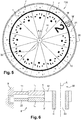
figure 4 représente un dispositif d'actionnement pour un système d'affichage tel que représenté à lafigure 3 ; - la
figure 5 représente un système d'affichage selon la présente invention comportant deux cadrans superposés selon les principes de lafigure 2 , pour afficher simultanément en en alignement les heures et les minutes dans une pièce d'horlogerie ; - la
figure 6 représente un dispositif d'actionnement pour un système d'affichage tel que représenté à lafigure 4 . - La présente invention se rapporte à un système d'affichage analogique comportant des modules d'affichage animés par l'intermédiaire d'un dispositif d'actionnement mécanique, notamment mais non exclusivement pour l'affichage d'une information horaire dans une pièce d'horlogerie, comme représenté et décrit ci-après aux
figures 1 à 6 . L'invention a également trait à une pièce d'horlogerie comportant un tel système d'affichage. - Bien qu'une application privilégiée de l'invention concerne le domaine de l'horlogerie, elle n'est pas limitée à un affichage d'une information horaire et peut également être mise en œuvre dans tout domaine requérant l'utilisation d'un système d'affichage d'une information ou représentation quelconque sous une forme animée.
- On a représenté sur les
figures 1A et 1B un module d'affichage 1 tel que décrit dans la demande co-pendanteCH01143/16 - Dans une forme la plus simple un tel module d'affichage 1 consiste en un module d'affichage d'un motif M tel qu'un chiffre ou un nombre comportant un bâti 2 fixe duquel sont solidaires au moins deux organes d'affichage, en l'espèce trois organes d'affichage 31, 32, 33 pour former le chiffre « 6 » (
figure 1B ). Les organes d'affichage 31, 32, 33 sont solidaires du bâti 2 et comportent chacun une portion d'affichage 31a, 32a, 33a du motif M, lesdites portions d'affichage étant complémentaires l'une de l'autre de sorte qu'elles forment ledit motif dans au moins une position relative desdits organes d'affichage 31, 32, 33. - A cet effet, les organes d'affichage 31, 32, 33 sont solidaires du bâti 2 et les organes 32, 33 sont également mobiles relativement au bâti 2 par l'intermédiaire d'au moins une liaison flexible 4 formée par au moins une lame flexible 41 entre une première position de repos, représentée sur la
figure 1A , dans laquelle les portions d'affichage des organes d'affichage 31, 32, 33 sont distantes l'une de l'autre et une position d'affichage, représentée sur lafigure 1B , dans laquelle lesdites portions d'affichage 31a, 32a, 33a sont contre-apposées l'une à l'autre pour former et afficher le motif M, en l'espèce un chiffre « 6 ». - Le déplacement des organes d'affichage 32, 33 relativement au bâti 2 autour de leur liaison flexible 4 entre les positions de repos et d'affichage résulte avantageusement selon l'invention de la coopération desdits organes d'affichage 32, 33 avec un poussoir d'actionnement 5 agencé relativement au bâti 2 et aux organes d'affichage pour transmettre un effort apte à induire un déplacement desdits organes d'affichage par déformation élastique autour de liaisons flexible également 4 consécutivement à l'action d'un dispositif d'actionnement 6 distinct du module d'affichage 1, tel qu'une came 61 mobile en rotation autour d'un axe A sur les
figures 1A et 1B , sur le poussoir d'actionnement 5. - Le module d'affichage 1 de l'invention est avantageusement constitué d'une pièce monolithique formée d'un matériau rigide, qu'on entend dans le cadre de la présente invention comme tout matériau dont le module d'Young est supérieur à 2.3 GPa. A ce titre un matériau de réalisation préféré du module d'affichage 1 de l'invention est le silicium, monocristallin ou polycristallin, à partir duquel on peut aisément, par exemple par des procédés de gravure profonde (notamment DRIE - pour Deep Reactive-ion Etching en anglais), former le bâti 2 et les organes d'affichage 31, 32, 33 reliés l'un à l'autre par au moins une liaison flexible 4, résultant notamment avantageusement de la formation lors du procédé de gravure profonde d'une ou plusieurs lames flexibles 4 d'une largeur comprise entre 2 et 50 microns, l'épaisseur du bâti 2 et du ou des organes d'affichage étant elle supérieure à 30 microns de préférence.
- Les organes d'affichage mobiles 32, 33 et leurs portions d'affichages 32a, 33a sont reliés directement au poussoir d'actionnement 5. L'organe d'affichage 31 lui reste identique à celui des
figures 1A et 1B . - Cette réalisation présente la particularité de ne présenter aucune interruption dans la chaine de commande du mouvement, depuis le poussoir d'actionnement 5 jusqu'aux portions d'affichages 32a, 33a. Il n'y a aucun frottement au sein du module d'affichage 1 dus aux mouvements, uniquement des déformations, donc une perte d'énergie minimale. Les portions d'affichage 32a, 33b sont connectées aux extrémités supérieures de deux bascules 32b et 33b, en rotation autour de liaisons flexibles 4 en forme de pivots flexibles en «papillon» 42 solidaires du bâti 2. L'extrémité inférieure de chacune des bascules et directement connectée au travers d'un ensemble 7 de lames flexibles en serpentin à un plateau 51 du poussoir d'actionnement 5, lequel est également solidaire du bâti 2 par une structure 8 de guidage en translation linéaire à lames flexible 81.
- Le fonctionnement et l'animation d'un tel module d'affichage 1 résulte de l'actionnement du poussoir 5, qui forme actionneur du module 1, par un dispositif d'actionnement 6 comportant une came 61 ou un ergot mobile en rotation autour d'un axe A pour lui imprimer un effort de poussée entrainant le passage des organes d'affichages 32, 33 et de leurs portions d'affichage 32a, 33a en particulier de la position de repos représentée
figure 1A à la position d'affichage représentée à lafigure 1B . - Les principes structurels et fonctionnels du module d'affichage 1 des
figures 1A et 1B peuvent être étendus pour la réalisation d'un cadran circulaire animé I comportant une pluralité de modules d'affichages 1 tel que représenté à lafigure 2 . Un tel cadran peut être mis en œuvre dans une pièce d'horlogerie telle qu'une montre ou une horloge pour l'affichage sous une forme animé de l'heure avec un dispositif d'actionnement 6 des poussoirs 5 disposés mobiles en rotation au centre du cadran et des modules d'affichage 1 est reliée cinématiquement à la roue des heures d'un mouvement horloger de la pièce d'horlogerie. - Le fonctionnement d'un tel système d'affichage est décrit ci-après en référence aux
figures 1A et 1B . Le dispositif d'actionnement 6 est représenté par une bague portant sur sa périphérie une protubérance formant une came 61. Ainsi, lors de la rotation de la bague 6, la came 61 vient pousser l'extrémité libre du poussoir d'actionnement 5 (figure 1B ) qui agit en tant que contact suiveur, et provoque un mouvement de translation du poussoir d'actionnement 5 qui pousse alors sur les bascules intermédiaires 32b, 33b qui pivotent par rapport au bâti 2 et ainsi entrainent le déplacement des portions d'affichages 32a, 33a vers la position d'affichage dans laquelle lesdites portions d'affichage s'ajustent avec la portion 31a pour former le motif « 6 » sur lafigure 1B . - Après le passage de la came 61 le contact suiveur du poussoir d'actionnement 5 revient en appui sur la bague 6, poussé par les forces de rappel des lames flexibles de la liaison déformable 4 au bâti 2. Les portions d'affichages 32a, 33a, s'écartent alors pour revenir vers la position de repos (
figure 1A ) et le motif n'est plus visible. - On réalise ainsi un système d'affichage animé comportant des portions d'affichage mobiles suivant une période déterminée pour engendrer un effet d'animation visuelle au sein de l'affichage.
- Afin de pouvoir procurer un affichage d'une information horaire de type heure-minutes pour une pièce d'horlogerie la présente invention complète l'enseignement de la demande
CH01143/16 figures 3 et5 , chaque cadran comportant chacun 12 modules d'affichage 1, 1' agencés concentriquement en une pièce monolithique formant le cadran I1, I2 autour d'un centre géométrique C par lequel passe un axe de rotation A d'un dispositif d'actionnement 6 comportant une ou deux cames 61, 62 comme décrit ci-après en référence auxfigures 4 et6 . Chacun des modules d'affichage 1, 1' forme ainsi un quartier ou secteur d'affichage horaire des cadrans I1, I2. - Chaque cadran I1, I2 est constitué d'une armature circulaire 10, 20 incorporant des poutres radiales 11, 21 qui supportent les modules d'affichages 1, 1' mis en mouvement par le déplacement de poussoirs d'actionnement 5, 5' présents dans chacun des quartiers horaires.
- Le premier cadran I1 est destiné à afficher les heures de façon séquentielle dans chacun des quartiers horaires en fonction de la valeur affichée. Le cadran I1 est de préférence, en utilisation dans une pièce d'horlogerie, fixé au bâti B de la pièce d'horlogerie, par exemple par l'intermédiaire d'une extension des poutres radiales 11. Le poussoir d'actionnement 5 est mis en mouvement par l'action de rotation d'une première came 61 du dispositif d'actionnement 6, en liaison cinématique sur la roue des heures H du rouage de finissage d'un mouvement horloger et qui vient en contact sur le poussoir d'actionnement 5.
- Le deuxième cadran I2 est destiné à afficher les minutes, par incrément de cinq minutes par exemple. Ce cadran I2 ne se situe pas dans le même plan que le cadran I1 mais lui est avantageusement superposé coaxialement à l'axe A.
- Dans l'exemple présenté dans la
Figure 3 le cadran I2 est situé sur le cadran I1 et le chiffre des minutes est affiché sur un diamètre différent du diamètre d'affichage des heures pour ne pas perturber la lecture de ces différentes valeurs. - Selon une première variante des
figures 3 et 4 , le cadran I2 est lui aussi comme le cadran I1 fixé au bâti B de la pièce d'horlogerie, par exemple par l'intermédiaire d'une extension des poutres radiales 21. Le dispositif d'actionnement 6 comporte lui deux cames 61 et 62 coopérant respectivement avec le poussoir actionneur 5 du cadran I1 pour afficher les heures dans les modules d'affichage 1 de ce cadran I1 et avec le poussoir actionneur 5' du cadran I2 pour afficher les minutes dans les modules d'affichage 1' du cadran I2. La came 61 est avantageusement solidaire d'un canon fixé à la roue des heures H du rouage de finissage du mouvement de la pièce d'horlogerie, alors que la came 62 est elle solidaire de la chaussée Mi du même rouage de finissage. On obtient ainsi un avantage des heures et des minutes tel que représenté sur lafigure 3 , avec heures et minutes décalées sur deux diamètres différents. - Selon une variante de réalisation représentée aux
figures 5 et 6 le cadran I2 est cette fois monté rotatif autour de l'axe A de rotation du dispositif d'actionnement, fixé sur un élément périphérique rotatif, un disque ou comme présenté ici une bague 22, par exemple par l'intermédiaire d'une extension des poutres radiales 21. La bague 22 est avantageusement agencée en liaison cinématique, par tout moyen connu de l'homme du métier en horlogerie, avec la roue des minutes du rouage de finissage du mouvement horloger, qui imprime à la bague 22 et au cadran I2 qui lui est solidaire une vitesse de rotation environ 12 fois supérieure à la vitesse de rotation d'une came 61 unique, solidaire du canon de la roue des heures H. - Dès lors, c'est la vitesse angulaire différentielle du cadran I2 par rapport à la roue des heures H qui provoque la mise en contact du poussoir d'actionnement 5' des modules d'affichage 1' du cadran I2 des minutes sur la came 61 et permet ainsi l'affichage séquentiel des minutes. Si le cadran I2 tourne dans le sens horaire avec une vitesse angulaire de 390°/heure, ou dans le sens antihoraire avec une vitesse angulaire de 330°/heure, alors l'affichage séquentiel des minutes s'effectue toujours des quartiers horaires des deux cadrans I1, I2 des heures et minutes absolument superposés angulairement autour de l'axe A de rotation, si bien que les affichages des heures et minutes sont alignés radialement à l'axe A et au centre C des cadrans. La position d'affichage des minutes suit donc l'évolution temporelle de la position d'affichage des heures.
- Par ailleurs, de façon avantageuse, comme indiqué sur la
Figure 6 , un trou 30 présent dans le canon de la roue des heures H, essentiellement dû à l'absence de chaussée des minutes et d'axe des secondes, libère un passage permettant le cas échéant de tirer des liaisons cinématiques entre le mouvement horloger, situé sous le système d'affichage 100, et un espace 50 situé au-dessus du système d'affichage 100 afin d'y amener des fonction supplémentaire, tel qu'un cadran à aiguille. Cet espace peut accueillir aussi une partie du mouvement horloger, par exemple l'organe régulateur du temps (ancre, roue d'échappement,...), Cet espace pourrait accueillir un tourbillon effectuant une rotation en cinq minutes en entraînant un index pointant sur un cadran gradué de 1 à 4, créant ainsi un affichage secondaire de la minute. - Dans une variante préférentielle, le premier et le second un module d'affichage 1, 1' sont agencés concentriquement l'un par rapport à l'autre autour d'un centre géométrique commun C, la distance du premier module d'affichage 1 du centre géométrique commun C étant différente de la distance du second module d'affichage 1'du centre géométrique commun C. En d'autres mots, le premier et le second un module d'affichage 1, 1' sont placés sur deux arcs de cercles ou sur deux circonférences ayant un centre géométrique commun C mais des rayons différents.
- Dans une variante, le premier et le second mobiles d'actionnement 61, 62 comportent une came 61 ou un ergot.
- Dans une variante, chaque module d'affichage 1, 1' est constitué de silicium monocristallin ou polycristallin.
- Dans une variante, le dispositif d'actionnement est mobile en rotation autour d'un axe de rotation A passant par le centre géométrique C.
- Dans une variante, le dispositif d'actionnement 6 est agencé pour exercer en au moins une position angulaire autour de l'axe de rotation A un effort apte à mobiliser l'actionneur 5, 5' de chaque module d'affichage 1, 1' de manière à déplacer lesdits organes d'affichage mobiles 32, 33 ; 32', 33' de la position de repos vers la position d'affichage pour former simultanément un dit motif M, M' sur chaque module d'affichage 1, 1'.
- Dans une variante, les au moins deux organes d'affichage 32, 33 ; 32', 33' sont solidaires et mobiles par rapport au bâti 2, 2' autour d'une liaison flexible 4, au moins entre ladite position de repos et ladite position d'affichage.
- Dans une variante, chaque module d'affichage comporte n organes d'affichage 31, 32, 33 ; 31', 32', 33', n étant un nombre entier supérieur à 1, au moins un organe d'affichage 31, 31' étant solidaire du bâti et immobile par rapport à celui-ci.
- Dans une variante, le dispositif d'actionnement 6 est lié cinématiquement au mobile des heures et un module d'affichage au moins est lié cinématiquement au mobile des minutes d'un mouvement horloger, le motif M, M' de chaque dit module d'affichage étant configuré pour afficher un quantième de temps.
Claims (14)
- Système d'affichage comportant :a. un premier et un second un module d'affichage (1, 1') agencés concentriquement l'un par rapport à l'autre autour d'un centre géométrique commun (C) et comportant chacun au moins deux organes d'affichage (31, 32, 33 ; 31', 32', 33') mobiles par rapport à un bâti (2, 2') entre une position de repos et une position d'affichage sous l'action d'au moins un actionneur (5, 5') pour former un motif (M, M'), etb. un dispositif d'actionnement (6) agencé pour coopérer avec l'actionneur (5, 5') de chaque module d'affichage (1, 1') et déplacer desdits organes d'affichage mobiles (32, 33 ; 32', 33') de la position de repos vers la position d'affichage pour former simultanément un dit motif (M, M') sur chaque module d'affichage (1, 1'),caractérisé en ce que
ledit au moins un actionneur (5, 5') de chaque module d'affichage (1, 1') est solidaire du bâti (2, 2') et mobile par rapport à celui-ci par l'intermédiaire d'une pluralité de liaisons flexibles (4). - Système d'affichage selon la revendication 1, caractérisé en ce que ledit au moins un actionneur (5, 5') de chaque module d'affichage (1, 1') s'étend suivant une direction radiale par rapport au centre géométrique (C).
- Système d'affichage selon l'une des revendications 1 à 2, caractérisé en ce que le dispositif d'actionnement (6) comporte un premier et un second mobiles d'actionnement (61, 62) agencés mobiles en rotation autour d'un axe de rotation (A) de manière à coopérer et mobiliser en au moins une position angulaire autour de l'axe de rotation (A) l'actionneur (5, 5') de chaque module d'affichage (1, 1').
- Système d'affichage selon la revendication 3, caractérisé en ce que le premier et le second mobiles d'actionnement (61, 62) sont indexés en rotation l'un par rapport à l'autre autour de l'axe de rotation (A).
- Système d'affichage selon l'une des revendications 3 à 4, caractérisé en ce que le premier et le second mobiles d'actionnement (61, 62) sont indexés en rotation l'un par rapport à l'autre autour de l'axe de rotation (A) de telle sorte que les motifs (M, M') simultanément formés sur chaque module d'affichage (1, 1') soient alignés suivant une même direction radiale depuis le centre géométrique (C).
- Système d'affichage selon l'une des revendications 1 à 2, caractérisé en ce que le dispositif d'actionnement (6) comporte un seul mobile d'actionnement (61) agencé pour coopérer simultanément en rotation avec l'actionneur (5, 5') de chaque module d'affichage (1, 1').
- Système d'affichage selon la revendication 6, caractérisé en ce qu'un module d'affichage (1') est agencé mobile en rotation autour de l'axe de rotation en référence à l'autre mobile d'affichage (1) et indexé en rotation par rapport au dit mobile d'actionnement (61) de telle sorte que les motifs (M, M') simultanément formés sur chaque module d'affichage (1, 1') soient alignés suivant une même direction radiale depuis le centre géométrique (C).
- Système d'affichage selon l'une des revendications précédentes, caractérisé en ce que les au moins deux organes d'affichage (32, 33 ; 32', 33') comportent une portion d'affichage (31a, 32a, 33a ; 31a', 32a', 33a') d'un dit motif (M, M') complémentaire d'une portion d'affichage d'un organe d'affichage d'un même module d'affichage (1, 1') au moins pour former le dit motif (M, M') dans au moins une position relative desdits organes d'affichage (31, 32, 33 ;31', 32', 33').
- Système d'affichage selon l'une des revendications 1 à 8, caractérisé en ce que chaque dit module d'affichage (1, 1') forme une pièce monolithique comportant lesdits organes d'affichage (31, 32, 33 ; 31', 32', 33'), le bâti (2, 2'), l'actionneur (5, 5') et une ou plusieurs liaisons déformables (4) reliant lesdits organes d'affichage et ledit actionneur au bâti (2, 2').
- Système d'affichage selon l'une des revendications précédentes, caractérisé en ce qu'il comporte un premier et un second cadran circulaires (I1, I2) superposés et concentriques par rapport au centre géométrique (C), chaque cadran (I1, I2) comportant m dits modules d'affichage (1, 1'), m étant un nombre entier, juxtaposés les uns aux autres autour du dispositif d'actionnement (6) concentriquement au centre géométrique (C) de telle sorte que celui-ci coopère simultanément, en une position angulaire donnée autour du centre (C) avec un poussoir d'actionnement (5, 5') d'un premier et d'un second module d'affichage (1, 1') de chaque dit cadran.
- Système d'affichage selon la revendication 10, caractérisé en ce que le nombre m de modules d'affichages (1, 1') de chacun des cadrans (l1, I2) est compris entre 4 et 24, de préférence entre 12 et 24.
- Système d'affichage selon l'une des revendications 10 ou 11, caractérisé en ce que chaque dit cadran circulaire (I1, I2) forme une pièce monolithique comportant lesdits m modules d'affichage.
- Pièce d'horlogerie caractérisée en ce qu'elle comporte un système d'affichage selon l'une des revendications 1 à 12, le dispositif d'actionnement (6) étant lié cinématiquement au mobile des heures et au mobile des minutes ou la chaussée d'un mouvement horloger, le motif (M, M') de chaque dit module d'affichage étant configuré pour afficher un quantième de temps.
- Pièce d'horlogerie caractérisée en ce qu'elle comporte un système d'affichage selon l'une des revendications 1 à 12, le dispositif d'actionnement (6) étant lié cinématiquement au mobile des heures et un module d'affichage au moins étant lié cinématiquement au mobile des minutes d'un mouvement horloger, le motif (M, M') de chaque dit module d'affichage étant configuré pour afficher un quantième de temps.
Applications Claiming Priority (2)
| Application Number | Priority Date | Filing Date | Title |
|---|---|---|---|
| CH00961/17A CH714014A1 (fr) | 2017-07-24 | 2017-07-24 | Système d'affichage comportant deux modules d'affichage par éléments mobiles autour de liaisons flexibles, et pièce d'horlogerie comportant un tel système d'affichage. |
| CH00962/17A CH714015A1 (fr) | 2017-07-24 | 2017-07-24 | Système d'affichage comportant deux modules d'affichage par éléments mobiles autour de liaisons flexibles, et pièce d'horlogerie comportant un tel système d'affichage. |
Publications (2)
| Publication Number | Publication Date |
|---|---|
| EP3435362A1 EP3435362A1 (fr) | 2019-01-30 |
| EP3435362B1 true EP3435362B1 (fr) | 2020-09-09 |
Family
ID=62842035
Family Applications (2)
| Application Number | Title | Priority Date | Filing Date |
|---|---|---|---|
| EP18184015.8A Active EP3435363B1 (fr) | 2017-07-24 | 2018-07-17 | Système d'affichage comportant un module d'affichage par éléments mobiles autour de liaisons flexibles, et pièce d'horlogerie comportant un tel système d'affichage |
| EP18184006.7A Active EP3435362B1 (fr) | 2017-07-24 | 2018-07-17 | Système d'affichage comportant un module d'affichage par elements mobiles autour de liaisons flexibles, et piece d'horlogerie comportant un tel système d'affichage |
Family Applications Before (1)
| Application Number | Title | Priority Date | Filing Date |
|---|---|---|---|
| EP18184015.8A Active EP3435363B1 (fr) | 2017-07-24 | 2018-07-17 | Système d'affichage comportant un module d'affichage par éléments mobiles autour de liaisons flexibles, et pièce d'horlogerie comportant un tel système d'affichage |
Country Status (2)
| Country | Link |
|---|---|
| EP (2) | EP3435363B1 (fr) |
| CH (1) | CH714015A1 (fr) |
Cited By (1)
| Publication number | Priority date | Publication date | Assignee | Title |
|---|---|---|---|---|
| EP4459382A1 (fr) * | 2023-05-03 | 2024-11-06 | Cartier International AG | Objet decoratif |
Families Citing this family (2)
| Publication number | Priority date | Publication date | Assignee | Title |
|---|---|---|---|---|
| CN114326355B (zh) * | 2021-12-31 | 2023-06-30 | 深圳市新隆达表业有限公司 | 一种可变表盘结构及具有该结构的手表 |
| CN116469311B (zh) * | 2023-03-20 | 2026-01-23 | 京东方科技集团股份有限公司 | 显示组件及显示装置 |
Family Cites Families (5)
| Publication number | Priority date | Publication date | Assignee | Title |
|---|---|---|---|---|
| US755272A (en) * | 1903-10-08 | 1904-03-22 | George E Burnham | Changeable sign. |
| JPS59176687A (ja) * | 1983-03-26 | 1984-10-06 | Mamoru Fujimoto | 24時表示時計 |
| JP4746623B2 (ja) * | 2004-08-30 | 2011-08-10 | ベエヌベ コンセプ エセア | 時計の文字盤にアニメ化された絵、図形又は記号を表示するための機構 |
| EP1784691A1 (fr) * | 2004-08-31 | 2007-05-16 | Dalton Properties Inc. | Mecanisme d'affichage de chiffres, figures ou signes animes sur un cadran de piece d'horlogerie |
| CH710331A2 (fr) * | 2014-11-05 | 2016-05-13 | Blancpain Sa | Mécanisme d'affichage de caractères pour pièce d'horlogerie. |
-
2017
- 2017-07-24 CH CH00962/17A patent/CH714015A1/fr not_active Application Discontinuation
-
2018
- 2018-07-17 EP EP18184015.8A patent/EP3435363B1/fr active Active
- 2018-07-17 EP EP18184006.7A patent/EP3435362B1/fr active Active
Non-Patent Citations (1)
| Title |
|---|
| None * |
Cited By (1)
| Publication number | Priority date | Publication date | Assignee | Title |
|---|---|---|---|---|
| EP4459382A1 (fr) * | 2023-05-03 | 2024-11-06 | Cartier International AG | Objet decoratif |
Also Published As
| Publication number | Publication date |
|---|---|
| EP3435363A1 (fr) | 2019-01-30 |
| EP3435362A1 (fr) | 2019-01-30 |
| EP3435363B1 (fr) | 2020-05-13 |
| CH714015A1 (fr) | 2019-01-31 |
Similar Documents
| Publication | Publication Date | Title |
|---|---|---|
| EP3291024B1 (fr) | Module d'affichage comportant des éléments mobiles autour de liaisons déformables, système d'affichage associé et pièce d'horlogerie comportant un tel système d'affichage | |
| EP0940833B1 (fr) | Mécanisme de quantième pour mouvement d'horlogerie | |
| CH684618B5 (fr) | Pièce d'horlogerie à affichage simultané de l'heure pour au moins deux fuseaux horaires. | |
| EP1546818A2 (fr) | Dispositif mecanique d affichage des heures et des minutes | |
| EP3435363B1 (fr) | Système d'affichage comportant un module d'affichage par éléments mobiles autour de liaisons flexibles, et pièce d'horlogerie comportant un tel système d'affichage | |
| EP3570119B1 (fr) | Mecanisme d'affichage d'un evenement periodique et piece d'horlogerie comportant un tel mecanisme | |
| EP0606576A1 (fr) | Calendrier musulman | |
| EP1158374A1 (fr) | Dispositif d'affichage de quantième | |
| EP3588204B1 (fr) | Module d'affichage par elements mobiles autour de liaisons flexibles, système d'affichage, et piece d'horlogerie le comportant | |
| EP2252918A1 (fr) | Mouvement horloger coaxial | |
| EP4500279B1 (fr) | Mouvement d'horlogerie comportant un dispositif d'affichage d'au moins deux fuseaux horaires | |
| EP4254079B1 (fr) | Mecanisme d'affichage des phases de lune de piece d'horlogerie | |
| CH714014A1 (fr) | Système d'affichage comportant deux modules d'affichage par éléments mobiles autour de liaisons flexibles, et pièce d'horlogerie comportant un tel système d'affichage. | |
| EP1475681A1 (fr) | Montre-chronographe à affichage instantané de fractions de seconde | |
| CH713226B1 (fr) | Dispositif d'affichage horloger. | |
| EP3579059B1 (fr) | Système d'affichage comportant un module d'affichage à organes mobiles autour de liaisons déformables et un dispositif de blocage reversible des dits organes mobiles dans au moins une position | |
| EP1353244B1 (fr) | Montre comportant une boîte de forme allongée | |
| EP3629100B1 (fr) | Dispositif de guidage symetrique de deux elements, notamment pour l'horlogerie | |
| EP3252543A1 (fr) | Dispositif d'affichage pour mouvement d'horlogerie | |
| CH712612A1 (fr) | Organe indicateur comportant au moins un élément mobile, système d'affichage associé et pièce d'horlogerie comportant un tel système d'affichage. | |
| CH720642A1 (fr) | Mécanisme d'horlogerie de quantième de célébration | |
| EP4361739A1 (fr) | Système de sélection de fonction pour montre | |
| CH718021B1 (fr) | Mécanisme d'affichage d'information, mouvement et pièce d'horlogerie | |
| CH712411B1 (fr) | Mouvement horloger comportant un dispositif d'affichage extra-plat de l'heure courante. | |
| CH718698B1 (fr) | Mécanisme horloger pour correction de plusieurs affichages. |
Legal Events
| Date | Code | Title | Description |
|---|---|---|---|
| PUAI | Public reference made under article 153(3) epc to a published international application that has entered the european phase |
Free format text: ORIGINAL CODE: 0009012 |
|
| STAA | Information on the status of an ep patent application or granted ep patent |
Free format text: STATUS: THE APPLICATION HAS BEEN PUBLISHED |
|
| AK | Designated contracting states |
Kind code of ref document: A1 Designated state(s): AL AT BE BG CH CY CZ DE DK EE ES FI FR GB GR HR HU IE IS IT LI LT LU LV MC MK MT NL NO PL PT RO RS SE SI SK SM TR |
|
| AX | Request for extension of the european patent |
Extension state: BA ME |
|
| STAA | Information on the status of an ep patent application or granted ep patent |
Free format text: STATUS: REQUEST FOR EXAMINATION WAS MADE |
|
| 17P | Request for examination filed |
Effective date: 20190709 |
|
| RBV | Designated contracting states (corrected) |
Designated state(s): AL AT BE BG CH CY CZ DE DK EE ES FI FR GB GR HR HU IE IS IT LI LT LU LV MC MK MT NL NO PL PT RO RS SE SI SK SM TR |
|
| GRAP | Despatch of communication of intention to grant a patent |
Free format text: ORIGINAL CODE: EPIDOSNIGR1 |
|
| STAA | Information on the status of an ep patent application or granted ep patent |
Free format text: STATUS: GRANT OF PATENT IS INTENDED |
|
| RIC1 | Information provided on ipc code assigned before grant |
Ipc: G04B 19/06 20060101ALI20200316BHEP Ipc: G09F 19/02 20060101AFI20200316BHEP Ipc: G09F 9/37 20060101ALI20200316BHEP Ipc: G04B 19/00 20060101ALI20200316BHEP Ipc: G04B 19/16 20060101ALI20200316BHEP Ipc: G04B 19/10 20060101ALI20200316BHEP Ipc: G04B 45/00 20060101ALI20200316BHEP |
|
| INTG | Intention to grant announced |
Effective date: 20200408 |
|
| RIN1 | Information on inventor provided before grant (corrected) |
Inventor name: CARDOT, FRANCIS |
|
| GRAJ | Information related to disapproval of communication of intention to grant by the applicant or resumption of examination proceedings by the epo deleted |
Free format text: ORIGINAL CODE: EPIDOSDIGR1 |
|
| STAA | Information on the status of an ep patent application or granted ep patent |
Free format text: STATUS: REQUEST FOR EXAMINATION WAS MADE |
|
| GRAR | Information related to intention to grant a patent recorded |
Free format text: ORIGINAL CODE: EPIDOSNIGR71 |
|
| GRAS | Grant fee paid |
Free format text: ORIGINAL CODE: EPIDOSNIGR3 |
|
| STAA | Information on the status of an ep patent application or granted ep patent |
Free format text: STATUS: GRANT OF PATENT IS INTENDED |
|
| INTC | Intention to grant announced (deleted) | ||
| GRAA | (expected) grant |
Free format text: ORIGINAL CODE: 0009210 |
|
| STAA | Information on the status of an ep patent application or granted ep patent |
Free format text: STATUS: THE PATENT HAS BEEN GRANTED |
|
| INTG | Intention to grant announced |
Effective date: 20200727 |
|
| AK | Designated contracting states |
Kind code of ref document: B1 Designated state(s): AL AT BE BG CH CY CZ DE DK EE ES FI FR GB GR HR HU IE IS IT LI LT LU LV MC MK MT NL NO PL PT RO RS SE SI SK SM TR |
|
| REG | Reference to a national code |
Ref country code: GB Ref legal event code: FG4D Free format text: NOT ENGLISH |
|
| REG | Reference to a national code |
Ref country code: AT Ref legal event code: REF Ref document number: 1312559 Country of ref document: AT Kind code of ref document: T Effective date: 20200915 Ref country code: CH Ref legal event code: EP |
|
| REG | Reference to a national code |
Ref country code: IE Ref legal event code: FG4D Free format text: LANGUAGE OF EP DOCUMENT: FRENCH |
|
| REG | Reference to a national code |
Ref country code: DE Ref legal event code: R096 Ref document number: 602018007557 Country of ref document: DE |
|
| REG | Reference to a national code |
Ref country code: CH Ref legal event code: NV Representative=s name: NOVAGRAAF INTERNATIONAL SA, CH |
|
| REG | Reference to a national code |
Ref country code: LT Ref legal event code: MG4D |
|
| PG25 | Lapsed in a contracting state [announced via postgrant information from national office to epo] |
Ref country code: FI Free format text: LAPSE BECAUSE OF FAILURE TO SUBMIT A TRANSLATION OF THE DESCRIPTION OR TO PAY THE FEE WITHIN THE PRESCRIBED TIME-LIMIT Effective date: 20200909 Ref country code: GR Free format text: LAPSE BECAUSE OF FAILURE TO SUBMIT A TRANSLATION OF THE DESCRIPTION OR TO PAY THE FEE WITHIN THE PRESCRIBED TIME-LIMIT Effective date: 20201210 Ref country code: HR Free format text: LAPSE BECAUSE OF FAILURE TO SUBMIT A TRANSLATION OF THE DESCRIPTION OR TO PAY THE FEE WITHIN THE PRESCRIBED TIME-LIMIT Effective date: 20200909 Ref country code: SE Free format text: LAPSE BECAUSE OF FAILURE TO SUBMIT A TRANSLATION OF THE DESCRIPTION OR TO PAY THE FEE WITHIN THE PRESCRIBED TIME-LIMIT Effective date: 20200909 Ref country code: BG Free format text: LAPSE BECAUSE OF FAILURE TO SUBMIT A TRANSLATION OF THE DESCRIPTION OR TO PAY THE FEE WITHIN THE PRESCRIBED TIME-LIMIT Effective date: 20201209 Ref country code: NO Free format text: LAPSE BECAUSE OF FAILURE TO SUBMIT A TRANSLATION OF THE DESCRIPTION OR TO PAY THE FEE WITHIN THE PRESCRIBED TIME-LIMIT Effective date: 20201209 Ref country code: LT Free format text: LAPSE BECAUSE OF FAILURE TO SUBMIT A TRANSLATION OF THE DESCRIPTION OR TO PAY THE FEE WITHIN THE PRESCRIBED TIME-LIMIT Effective date: 20200909 |
|
| REG | Reference to a national code |
Ref country code: AT Ref legal event code: MK05 Ref document number: 1312559 Country of ref document: AT Kind code of ref document: T Effective date: 20200909 |
|
| REG | Reference to a national code |
Ref country code: NL Ref legal event code: MP Effective date: 20200909 |
|
| PG25 | Lapsed in a contracting state [announced via postgrant information from national office to epo] |
Ref country code: PL Free format text: LAPSE BECAUSE OF FAILURE TO SUBMIT A TRANSLATION OF THE DESCRIPTION OR TO PAY THE FEE WITHIN THE PRESCRIBED TIME-LIMIT Effective date: 20200909 Ref country code: RS Free format text: LAPSE BECAUSE OF FAILURE TO SUBMIT A TRANSLATION OF THE DESCRIPTION OR TO PAY THE FEE WITHIN THE PRESCRIBED TIME-LIMIT Effective date: 20200909 Ref country code: LV Free format text: LAPSE BECAUSE OF FAILURE TO SUBMIT A TRANSLATION OF THE DESCRIPTION OR TO PAY THE FEE WITHIN THE PRESCRIBED TIME-LIMIT Effective date: 20200909 |
|
| PG25 | Lapsed in a contracting state [announced via postgrant information from national office to epo] |
Ref country code: SM Free format text: LAPSE BECAUSE OF FAILURE TO SUBMIT A TRANSLATION OF THE DESCRIPTION OR TO PAY THE FEE WITHIN THE PRESCRIBED TIME-LIMIT Effective date: 20200909 Ref country code: CZ Free format text: LAPSE BECAUSE OF FAILURE TO SUBMIT A TRANSLATION OF THE DESCRIPTION OR TO PAY THE FEE WITHIN THE PRESCRIBED TIME-LIMIT Effective date: 20200909 Ref country code: PT Free format text: LAPSE BECAUSE OF FAILURE TO SUBMIT A TRANSLATION OF THE DESCRIPTION OR TO PAY THE FEE WITHIN THE PRESCRIBED TIME-LIMIT Effective date: 20210111 Ref country code: RO Free format text: LAPSE BECAUSE OF FAILURE TO SUBMIT A TRANSLATION OF THE DESCRIPTION OR TO PAY THE FEE WITHIN THE PRESCRIBED TIME-LIMIT Effective date: 20200909 Ref country code: EE Free format text: LAPSE BECAUSE OF FAILURE TO SUBMIT A TRANSLATION OF THE DESCRIPTION OR TO PAY THE FEE WITHIN THE PRESCRIBED TIME-LIMIT Effective date: 20200909 |
|
| PG25 | Lapsed in a contracting state [announced via postgrant information from national office to epo] |
Ref country code: AT Free format text: LAPSE BECAUSE OF FAILURE TO SUBMIT A TRANSLATION OF THE DESCRIPTION OR TO PAY THE FEE WITHIN THE PRESCRIBED TIME-LIMIT Effective date: 20200909 Ref country code: AL Free format text: LAPSE BECAUSE OF FAILURE TO SUBMIT A TRANSLATION OF THE DESCRIPTION OR TO PAY THE FEE WITHIN THE PRESCRIBED TIME-LIMIT Effective date: 20200909 Ref country code: ES Free format text: LAPSE BECAUSE OF FAILURE TO SUBMIT A TRANSLATION OF THE DESCRIPTION OR TO PAY THE FEE WITHIN THE PRESCRIBED TIME-LIMIT Effective date: 20200909 Ref country code: IS Free format text: LAPSE BECAUSE OF FAILURE TO SUBMIT A TRANSLATION OF THE DESCRIPTION OR TO PAY THE FEE WITHIN THE PRESCRIBED TIME-LIMIT Effective date: 20210109 |
|
| REG | Reference to a national code |
Ref country code: DE Ref legal event code: R097 Ref document number: 602018007557 Country of ref document: DE |
|
| PG25 | Lapsed in a contracting state [announced via postgrant information from national office to epo] |
Ref country code: SK Free format text: LAPSE BECAUSE OF FAILURE TO SUBMIT A TRANSLATION OF THE DESCRIPTION OR TO PAY THE FEE WITHIN THE PRESCRIBED TIME-LIMIT Effective date: 20200909 |
|
| PLBE | No opposition filed within time limit |
Free format text: ORIGINAL CODE: 0009261 |
|
| STAA | Information on the status of an ep patent application or granted ep patent |
Free format text: STATUS: NO OPPOSITION FILED WITHIN TIME LIMIT |
|
| 26N | No opposition filed |
Effective date: 20210610 |
|
| PG25 | Lapsed in a contracting state [announced via postgrant information from national office to epo] |
Ref country code: SI Free format text: LAPSE BECAUSE OF FAILURE TO SUBMIT A TRANSLATION OF THE DESCRIPTION OR TO PAY THE FEE WITHIN THE PRESCRIBED TIME-LIMIT Effective date: 20200909 Ref country code: DK Free format text: LAPSE BECAUSE OF FAILURE TO SUBMIT A TRANSLATION OF THE DESCRIPTION OR TO PAY THE FEE WITHIN THE PRESCRIBED TIME-LIMIT Effective date: 20200909 |
|
| PG25 | Lapsed in a contracting state [announced via postgrant information from national office to epo] |
Ref country code: IT Free format text: LAPSE BECAUSE OF FAILURE TO SUBMIT A TRANSLATION OF THE DESCRIPTION OR TO PAY THE FEE WITHIN THE PRESCRIBED TIME-LIMIT Effective date: 20200909 |
|
| PG25 | Lapsed in a contracting state [announced via postgrant information from national office to epo] |
Ref country code: MC Free format text: LAPSE BECAUSE OF FAILURE TO SUBMIT A TRANSLATION OF THE DESCRIPTION OR TO PAY THE FEE WITHIN THE PRESCRIBED TIME-LIMIT Effective date: 20200909 |
|
| REG | Reference to a national code |
Ref country code: BE Ref legal event code: MM Effective date: 20210731 |
|
| PG25 | Lapsed in a contracting state [announced via postgrant information from national office to epo] |
Ref country code: LU Free format text: LAPSE BECAUSE OF NON-PAYMENT OF DUE FEES Effective date: 20210717 |
|
| PG25 | Lapsed in a contracting state [announced via postgrant information from national office to epo] |
Ref country code: IE Free format text: LAPSE BECAUSE OF NON-PAYMENT OF DUE FEES Effective date: 20210717 Ref country code: BE Free format text: LAPSE BECAUSE OF NON-PAYMENT OF DUE FEES Effective date: 20210731 |
|
| PG25 | Lapsed in a contracting state [announced via postgrant information from national office to epo] |
Ref country code: NL Free format text: LAPSE BECAUSE OF NON-PAYMENT OF DUE FEES Effective date: 20200923 Ref country code: CY Free format text: LAPSE BECAUSE OF FAILURE TO SUBMIT A TRANSLATION OF THE DESCRIPTION OR TO PAY THE FEE WITHIN THE PRESCRIBED TIME-LIMIT Effective date: 20200909 |
|
| PG25 | Lapsed in a contracting state [announced via postgrant information from national office to epo] |
Ref country code: HU Free format text: LAPSE BECAUSE OF FAILURE TO SUBMIT A TRANSLATION OF THE DESCRIPTION OR TO PAY THE FEE WITHIN THE PRESCRIBED TIME-LIMIT; INVALID AB INITIO Effective date: 20180717 |
|
| PG25 | Lapsed in a contracting state [announced via postgrant information from national office to epo] |
Ref country code: MK Free format text: LAPSE BECAUSE OF FAILURE TO SUBMIT A TRANSLATION OF THE DESCRIPTION OR TO PAY THE FEE WITHIN THE PRESCRIBED TIME-LIMIT Effective date: 20200909 |
|
| PG25 | Lapsed in a contracting state [announced via postgrant information from national office to epo] |
Ref country code: MT Free format text: LAPSE BECAUSE OF FAILURE TO SUBMIT A TRANSLATION OF THE DESCRIPTION OR TO PAY THE FEE WITHIN THE PRESCRIBED TIME-LIMIT Effective date: 20200909 |
|
| PG25 | Lapsed in a contracting state [announced via postgrant information from national office to epo] |
Ref country code: TR Free format text: LAPSE BECAUSE OF FAILURE TO SUBMIT A TRANSLATION OF THE DESCRIPTION OR TO PAY THE FEE WITHIN THE PRESCRIBED TIME-LIMIT Effective date: 20200909 |
|
| REG | Reference to a national code |
Ref country code: CH Ref legal event code: U11 Free format text: ST27 STATUS EVENT CODE: U-0-0-U10-U11 (AS PROVIDED BY THE NATIONAL OFFICE) Effective date: 20260115 |
|
| PGFP | Annual fee paid to national office [announced via postgrant information from national office to epo] |
Ref country code: GB Payment date: 20260115 Year of fee payment: 8 |
|
| PGFP | Annual fee paid to national office [announced via postgrant information from national office to epo] |
Ref country code: DE Payment date: 20260120 Year of fee payment: 8 |
|
| PGFP | Annual fee paid to national office [announced via postgrant information from national office to epo] |
Ref country code: FR Payment date: 20260116 Year of fee payment: 8 |
|
| PGFP | Annual fee paid to national office [announced via postgrant information from national office to epo] |
Ref country code: CH Payment date: 20260115 Year of fee payment: 8 |