EP3435501A1 - Kabelkanal - Google Patents
Kabelkanal Download PDFInfo
- Publication number
- EP3435501A1 EP3435501A1 EP18185188.2A EP18185188A EP3435501A1 EP 3435501 A1 EP3435501 A1 EP 3435501A1 EP 18185188 A EP18185188 A EP 18185188A EP 3435501 A1 EP3435501 A1 EP 3435501A1
- Authority
- EP
- European Patent Office
- Prior art keywords
- cable
- holes
- cable duct
- longitudinal direction
- web
- Prior art date
- Legal status (The legal status is an assumption and is not a legal conclusion. Google has not performed a legal analysis and makes no representation as to the accuracy of the status listed.)
- Granted
Links
Images


Classifications
-
- H—ELECTRICITY
- H02—GENERATION; CONVERSION OR DISTRIBUTION OF ELECTRIC POWER
- H02G—INSTALLATION OF ELECTRIC CABLES OR LINES, OR OF COMBINED OPTICAL AND ELECTRIC CABLES OR LINES
- H02G3/00—Installations of electric cables or lines or protective tubing therefor in or on buildings, equivalent structures or vehicles
- H02G3/02—Details
- H02G3/04—Protective tubing or conduits, e.g. cable ladders or cable troughs
- H02G3/0437—Channels
- H02G3/045—Channels provided with perforations or slots permitting introduction or exit of wires
-
- H—ELECTRICITY
- H02—GENERATION; CONVERSION OR DISTRIBUTION OF ELECTRIC POWER
- H02G—INSTALLATION OF ELECTRIC CABLES OR LINES, OR OF COMBINED OPTICAL AND ELECTRIC CABLES OR LINES
- H02G3/00—Installations of electric cables or lines or protective tubing therefor in or on buildings, equivalent structures or vehicles
- H02G3/30—Installations of cables or lines on walls, floors or ceilings
- H02G3/32—Installations of cables or lines on walls, floors or ceilings using mounting clamps
Definitions
- the invention relates to a cable duct according to the preamble of claim 1, further to a cable duct arrangement which has such a cable duct, and to a rail vehicle which has such a cable duct.
- the proposed cable duct can be used in the electrical equipment of plants, especially in rail vehicles.
- Such a cable duct is particularly suitable for receiving a plurality of cables and for guiding them along a wall, for example through a room.
- the use of such a channel protects the cables from external influences and thus increases their possible operating time.
- security is improved because the cables are not directly accessible and embellish the environment by hiding the cables in the cable channel.
- dividers in the channel which extend in the longitudinal direction of the channel and separate different compartments of predetermined width within the cable channel.
- the invention has for its object to provide a cable channel, which has a greater flexibility in terms of the assembly with cables and thus allows greater standardization.
- the cable channel according to the invention allows greater variability of Positioning of the dividers in the transverse direction of the cable channel as known cable channels.
- Another embodiment relates to a cable channel extending along a longitudinal direction comprising two side walls and a bottom interconnecting the side walls, the cable channel further comprising mounting holes for securing the cables received in the cable channel to the bottom of the cable channel, the mounting holes passing through extend through the bottom and each mounting hole has an edge and two tabs which protrude from the edge into the mounting hole and each tab comprises a fastening web and a holding web connected to the mounting web, the mounting web is connected at one end to the edge and the holding part forms a free end of the tab and wherein the width of the holding part is greater than the width of the fastening web.
- FIG. 1 shows a cable channel 1 according to the invention in a perspective view.
- the cable channel 1 extends along a longitudinal axis X-X.
- the cable channel 1 has two side walls 7 and a bottom 9, which connects the side walls 7 together.
- the side walls 7 extend substantially perpendicular to the bottom 9 and parallel to each other.
- the bottom 9 and the side walls 7 are preferably made in one piece, for example by bending and optionally cutting out a suitable sheet.
- the side walls 7 may be connected to the bottom 9 by a suitable connection means, for example by a respective weld.
- the side walls 9 recesses 11. These recesses 11 extend over the entire height of the side walls 9. They have a rectangular contour.
- the recesses 11 of a respective side wall 9 are spaced apart in the longitudinal direction of the side wall 9, in particular regularly spaced from each other.
- the recesses 11 serve to allow the cables received in the cable channel 1 a lateral output from the cable channel 1, for example, if due to the space situation, no output upwards from the cable channel 1 is possible.
- the bottom 9 and the side walls 7 define an interior space 12 for receiving cables.
- the cable duct 1 comprises at least two compartments 13 for receiving cables.
- the compartments 13 are formed in the interior 12 of the cable channel 1. They extend in the longitudinal direction X-X of the cable channel 1.
- Each compartment 13 preferably receives only cables of a certain class, and in particular all cables of this class.
- the cable channel 1 has a plurality of first attachment holes 25 for attaching the cables to the cable channel 1.
- the first attachment holes 25 are formed in the bottom 9 of the cable channel 1 and extend through the bottom 9 therethrough.
- All first mounting holes 25 have identical dimensions, that is, in particular a same length and width.
- the first mounting holes 25 extend in a plurality of transversely spaced longitudinal rows along the length of the cable channel 1. The longitudinal axes of the first mounting holes 25 of each row are aligned.
- first mounting holes 25 are evenly spaced apart, particularly in the transverse direction.
- first mounting holes 25 are arranged in relation to each other such that the first mounting holes 25 form transverse rows in the transverse direction.
- the first mounting holes 25 serve to tie the cable received in the cable channel 1 at the bottom of the cable channel 1.
- cable ties (not shown) are threaded through two transversely adjacent first mounting holes 25 so that they form a loop which extends around the cable and around the bottom web 26 formed between the two mounting holes 25.
- the cable duct 1 also comprises at least one separating web 15.
- Each separating web 15 extends in the longitudinal direction XX in the interior 12 of the cable channel 1 between the side walls 7. As in FIG. 1 shown, each divider 15 extends perpendicular to the bottom 5 of the cable channel 1 and parallel to the side walls. 7
- Each compartment 13 is delimited laterally either by two adjacent separating webs 15 or by a separating web 15 and a side wall 7.
- the dividers 15 serve to separate different cables or groups of cables that are received in the cable channel 1 from each other. This is particularly important if in a cable duct 1 cables of different cable classes are included, for example, both cables for data transmission, as well as low-voltage and / or high voltage cable.
- Each divider 15 is located at its lower edge 19 on the bottom 9.
- Each divider 15 is formed by a wall which extends substantially in one plane.
- each connecting lug 21 is connected to the lower edge 19 of the respective separating web 15 and extends perpendicularly to the separating web 15.
- a plurality of connecting tabs 21 spaced apart from one another in the longitudinal direction of the separating web 15 are arranged on each separating web 15.
- the arranged on a respective separating web 15 connecting straps 21 are in particular evenly spaced from each other.
- the cable channel 1 has a plurality of connecting holes 27 for connecting the separating webs 15 to the cable channel 1.
- the connecting holes 27 serve to receive the connecting straps 21. They are formed in the bottom 9 of the cable duct 1 and extend through the bottom 9 therethrough.
- the connecting holes 27 are elongated in the longitudinal direction XX of the cable channel 1. They have a length that is greater than their width.
- Each connecting hole 27 comprises two longitudinal sides 35 which run parallel to one another and two transverse sides 37 which connect these longitudinal sides 35 at their ends.
- the connecting holes 27 in plan view on a rectangular contour.
- the connecting holes 27 may also be formed as elongated holes, that is, with semicircular transverse sides 37.
- All communication holes 27 have identical dimensions, ie in particular an equal length and width.
- the width of the communication holes 27, transverse to the longitudinal direction X-X, is greater than the width of the first mounting holes 25.
- connection holes 27 is greater than the thickness of the separating webs 15 in the longitudinal direction.
- the communication holes 27 extend in a plurality of transversely spaced longitudinal rows along the length of the conduit 1. The longitudinal axes of the communication holes 27 of each row are aligned.
- the longitudinal rows of connecting holes 27 are arranged in relation to each other such that the connecting holes 27 form transverse rows in the transverse direction.
- the connecting holes 27 of a respective row are adapted to receive the connecting tabs 21 of a separating web 15.
- the communication holes 27 in a row are arranged such that each connection tab 21 of the partition ribs 15 can be inserted into a respective communication hole 27.
- the distance between two adjacent connection holes 27 corresponds to the distance between two adjacent connection tabs 21 on a separating web 15.
- each longitudinal row of connecting holes 27 extends between two adjacent rows of first mounting holes 25. More specifically, the longitudinal rows of connecting holes 27 in this example are arranged such that either two longitudinal rows of connecting holes 27 alternate between two adjacent longitudinal rows of first mounting holes 25 or no longitudinal row of connecting holes 27 extends.
- each transverse row of connecting holes 27 extends between adjacent transverse rows of first mounting holes 25.
- the connecting holes 27 are shaped in such a way that the connecting straps 21 of the separating webs 15 can be guided through the connecting holes 27 when the separating webs 15 are arranged in the inner space 12 of the cable channel 1 over a longitudinal row of connecting holes 27.
- the connecting straps 21 are connected to the bottom 9 via suitable connecting means.
- the connecting straps 21 are preferably connected to the bottom 9 on the outside 40 thereof by welding, in particular spot welding, or by clinching, also called clinching.
- the cable channel 1 further includes optional second attachment holes 45 which also serve to tie the cables to the conduit 1.
- the second mounting holes 45 are formed in the bottom 9 of the cable channel 1 and extend through the bottom 9 therethrough.
- the second fastening holes 45 are arranged in rows which extend in the transverse direction of the cable channel 1.
- each row of second mounting holes 45 extends between a transverse row of connecting holes 27 and a transverse row of first mounting holes 25.
- each second mounting hole 45 has an edge 50 and two tabs 52 which project from the edge 50 into the hole 45.
- Each tab 52 extends in the plane of the bottom 9 along a longitudinal axis Y-Y, which extends parallel to the longitudinal direction X-X of the cable channel 1.
- Each tab 52 includes a fastening web 54 which is connected at one end to the edge and extends along the longitudinal axis Y-Y and a holding part 56 which is connected to the fastening web 54 and extends transversely to the longitudinal direction.
- the holding part 56 forms a free end of the tab 52.
- the width b 1 of the holding part 56 is greater than the width b 2 of the fixing web 54, wherein b 1 and b 2 are measured transversely to the longitudinal direction of the tab 52.
- the two tabs 52 of a respective mounting hole 45 are symmetrical relative to a plane of symmetry which extends perpendicular to the bottom 9 and transverse to the longitudinal direction X-X.
- the second mounting holes 45 are disposed on the bottom 9 such that the tabs 52 extend longitudinally in the extension of the bottom webs 26 between two transversely adjacent first mounting holes 25. This makes it possible to fasten a respective cable both via first fastening holes 25 and via second fastening holes 45, depending on the distance at which the cable to be tied at the bottom 9 and whether the outside of the channel 1 is accessible.
- the connecting holes 27 are shown in particular just as wide that the distance a 1 , transverse to the longitudinal direction XX, between two opposite longitudinal sides 35 of two adjacent connecting holes 27 is larger, in particular slightly larger than the distance a 2 between two adjacent mounting holes 45th des Furthermore, the width of the connecting holes 27 is particularly dimensioned such that the distance c between the adjacent connecting holes 27 is large enough to ensure the required stability of the cable channel 1.
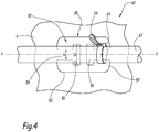
- the FIG. 4 shows an assembly 60, which has the cable channel 1, a cable 62 and a cable tie 64.
- the cable tie 64 includes a head 64, and a strap 66 connected at a first end to the head 64.
- the band 66 is intended to be pulled through an opening provided in the head 64, thus forming a loop.
- the cable 62 extends substantially in the longitudinal direction X-X of the cable channel 1 and is connected via the cable tie 64 to the bottom of the cable channel 1.
- the cable 62 is connected to the cable channel 1 via a second attachment hole 45.
- the cable tie 64 is connected to a tab 52 of a second attachment hole 45.
- the cable tie 64 forms a loop which tightly encloses the cable 62 and the fastening web 54 of the tab 52.
- the holding member 56 forms a stop for the cable tie 64 in the longitudinal direction by limiting a displacement of the cable tie 64 in the longitudinal direction.
- the holding part 56 in particular prevents slipping off the cable tie 64 from the fastening web 54.
- the cable 62 is connected by the cable tie 64 via first mounting holes 25 to the bottom 9 of the cable channel 1.
- the cable tie is guided by two transversely adjacent first mounting holes 25 and thus forms a loop around the cable 62 and the bottom web 26 between the holes 25.
- the assembly 60 may be advantageously used in a rail vehicle, for example.
- the cable channel 1 according to the invention is particularly advantageous, since it 27 by the provision of additional, wider connection holes a greater variability of the positioning of the dividers 21 in the transverse direction of the cable channel 1 as cable channels which only have first mounting holes 25, both for attachment of the dividers, as also serve to attach the cable.
- the positions of the separating webs 15 can be varied across the width of a respective, wide connecting hole 27, depending on the desired width of the cable compartments 13, so that a large number of possible compartment widths is created.
- the compartments 13 need not necessarily have a width which corresponds to an integer multiple of the distance between two adjacent first mounting holes 25, as is the case with known cable ducts.
- first mounting holes 25 free for the inclusion of cable ties. Furthermore, according to the invention, there is no risk that the connecting tabs 21 of the dividers overlap the first or second mounting holes 25, 45, because the communicating holes 27 extend in transverse rows between the transverse rows of first and second mounting holes 25, 45.
- the additional, second mounting holes 45 are also advantageous since they allow the cables to be tied to the cable channel 1 when only one side of the cable channel 1 is accessible, while it is necessary for fixing the cables by means of the first mounting holes that the cable channel 1 also accessible from outside to thread the cable ties through the mounting holes can.
- the second attachment holes 45 could optionally be made in a conduit 1 independently of the communication holes 27.
Landscapes
- Engineering & Computer Science (AREA)
- Architecture (AREA)
- Civil Engineering (AREA)
- Structural Engineering (AREA)
- Details Of Indoor Wiring (AREA)
- Supports For Pipes And Cables (AREA)
- Manufacturing Of Electric Cables (AREA)
Abstract
- zwei Seitenwände (7) und einen Boden (9), welcher die Seitenwände (7) miteinander verbindet,
- eine Mehrzahl von Befestigungslöchern zum Befestigen der im Kabelkanal (1) aufgenommenen Kabel am Boden des Kabelkanals (1), wobei sich die ersten Befestigungslöcher durch den Boden (9) hindurch erstrecken.
Description
- Die Erfindung bezieht sich auf einen Kabelkanal gemäß dem Oberbegriff des Anspruchs 1, des Weiteren auf eine Kabelkanalanordnung welche einen solchen Kabelkanal aufweist, sowie auf ein Schienenfahrzeug, welches einen solchen Kabelkanal aufweist.
- Der vorgeschlagene Kabelkanal kann bei der elektrischen Ausrüstung von Anlagen, insbesondere auch bei Schienenfahrzeugen, verwendet werden.
- Ein solcher Kabelkanal ist insbesondere dazu geeignet, mehrere Kabel aufzunehmen und an einer Wand entlang, zum Beispiel durch einen Raum, zu führen. Dabei schützt die Benutzung eines solchen Kanals die Kabel vor Außeneinflüssen und erhöht somit ihre mögliche Betriebszeit. Außerdem wird die Sicherheit verbessert, da die Kabel nicht direkt zugänglich sind und die Umgebung durch das Verstecken der Kabel im Kabelkanal verschönert.
- Dies ist in Schienenfahrzeugen besonders wichtig, da dort, aufgrund der vielen elektrischen und elektronischen Systeme, auf relativ engem Raum, viele Kabel verschiedener Klassen verlaufen müssen. Dabei ist es wichtig, dass Kabel verschiedener Klassen, zum Beispiel Niederspannungs-, Hochspannungs- und Datenkabel voneinander getrennt und abgeschirmt sind.
- Dies kann dadurch erreicht werden, dass im Kanal Trennstege vorgesehen werden, welche sich in Längsrichtung des Kanals erstrecken und innerhalb des Kabelkanals verschiedene Abteile vorbestimmter Breite abtrennen. Dafür weisen die Kabelkanäle Reihen von schmalen Langlöchern auf, die sowohl dazu dienen, die Trennstege mit dem Boden des Kanals zu verbinden, als auch die im Kabelkanal aufgenommenen Kabel über Kabelbinder, welche durch zwei benachbarte Langlöcher durchgefädelt werden, an dem Kabelkanal festzubinden.
- Solche Kabelkanäle haben den Nachteil, dass sie wenig Flexibilität in Hinsicht auf die Bestückung mit Kabeln aufweisen.
- Der Erfindung liegt die Aufgabe zugrunde, einen Kabelkanal anzugeben, der eine größere Flexibilität in Hinsicht auf die Bestückung mit Kabeln aufweist und somit eine größere Standardisierung erlaubt.
- Erfindungsgemäß wird diese Aufgabe gelöst durch die Merkmale des Oberbegriffs des Anspruchs 1 in Verbindung mit den Merkmalen des kennzeichnenden Teils.
- Durch das Vorsehen des erfindungsgemäßen Lochmusters im Kabelkanal mit zusätzlichen Verbindungslöchern für die Trennstege, die breiter sind als die schmalen Verbindungslanglöcher, die üblicherweise zur Verbindung der Trennstege mit dem Kanal benutzt werden, erlaubt der erfindungsgemäße Kabelkanal eine größere Variabilität der Positionierung der Trennstege in Querrichtung des Kabelkanals als bekannte Kabelkanäle.
- Dadurch ist es möglich, für jede Anwendung die Breite der Kabelabteile des Kabelkanals an die Anzahl der darin aufzunehmenden Kabel weitgehend anzupassen. Somit werden sehr unterschiedliche Belegungen des Kabelkanals mit Kabeln ermöglicht, was die Standardisierung der Kabelkanäle unterstützt.
- Vorteilhafte Ausgestaltungen der Erfindung sind in den Unteransprüchen gekennzeichnet.
- Eine andere Ausführungsform betrifft einen Kabelkanal, welcher sich entlang einer Längsrichtung erstreckt, umfassend zwei Seitenwände und einen Boden, welcher die Seitenwände miteinander verbindet, wobei der Kabelkanal außerdem Befestigungslöcher zum Befestigen der im Kabelkanal aufgenommenen Kabel am Boden des Kabelkanals aufweist, wobei sich die Befestigungslöcher durch den Boden hindurch erstrecken und jedes Befestigungsloch einen Rand und zwei Laschen aufweist, welche vom Rand aus in das Befestigungsloch hineinragen und jede Lasche einen Befestigungssteg und ein mit dem Befestigungssteg verbundenes Halteteil umfasst, wobei der Befestigungssteg an einem Ende mit dem Rand verbunden ist und das Halteteil ein freies Ende der Lasche bildet und wobei die Breite des Halteteils größer ist als die Breite des Befestigungsstegs.
- Weitere Vorteile des erfindungsgemäßen Kabelkanals ergeben sich aus der nachstehenden Beschreibung.
- Die Erfindung wird nachstehend anhand der in den Zeichnungen dargestellten Ausführungsbeispiele näher erläutert, wobei:
-
Figur 1 einen erfindungsgemäßen Kabelkanal in perspektivischer Ansicht zeigt; -
Figur 2 einen Teil des Kabelkanals derFigur 1 in einer Ansicht von unten zeigt, -
Figur 3 ein Detail derFigur 2 zeigt, und -
Figur 4 eine Draufsicht auf ein Kabel zeigt, welches über ein zweites Befestigungsloch befestigt ist. - Die
Figur 1 zeigt einen erfindungsgemäßen Kabelkanal 1 in perspektivischer Ansicht. - Der Kabelkanal 1 erstreckt sich entlang einer Längsachse X-X.
- Wie in
Figur 1 gezeigt, weist der Kabelkanal 1 zwei Seitenwände 7 und einen Boden 9 auf, welcher die Seitenwände 7 miteinander verbindet. Die Seitenwände 7 erstrecken sich im Wesentlichen senkrecht zum Boden 9 und parallel zueinander. - Der Boden 9 und die Seitenwände 7 sind bevorzugt aus einem Stück hergestellt, zum Beispiel durch Biegen und gegebenenfalls Ausschneiden eines geeigneten Blechs.
- Alternativ können die Seitenwände 7 mit dem Boden 9 durch ein geeignetes Verbindungsmittel verbunden sein, zum Beispiel durch eine jeweilige Schweißnaht.
- In der abgebildeten Ausführungsform weisen die Seitenwände 9 Ausnehmungen 11 auf. Diese Ausnehmungen 11 erstrecken sich über die gesamte Höhe der Seitenwände 9. Sie weisen eine rechteckige Kontur auf. Die Ausnehmungen 11 einer jeweiligen Seitenwand 9 sind in Längsrichtung der Seitenwand 9 voneinander beabstandet, insbesondere regelmäßig voneinander beabstandet. Die Ausnehmungen 11 dienen dazu, den im Kabelkanal 1 aufgenommenen Kabeln einen seitlichen Ausgang aus dem Kabelkanal 1 zu ermöglichen, zum Beispiel wenn aufgrund der Bauraumsituation kein Ausgang nach oben aus dem Kabelkanal 1 möglich ist.
- Der Boden 9 und die Seitenwände 7 grenzen einen Innenraum 12 zur Aufnahme von Kabeln ab.
- Der Kabelkanal 1 umfasst zumindest zwei Abteile 13 zur Aufnahme von Kabeln. Die Abteile 13 sind im Innenraum 12 des Kabelkanals 1 gebildet. Sie erstrecken sich in Längsrichtung X-X des Kabelkanals 1. Jedes Abteil 13 nimmt bevorzugt nur Kabel einer bestimmten Klasse auf, und insbesondere alle Kabel dieser Klasse.
- Der Kabelkanal 1 weist eine Mehrzahl von ersten Befestigungslöchern 25 zum Befestigen der Kabel am Kabelkanal 1. Die ersten Befestigungslöcher 25 sind im Boden 9 des Kabelkanals 1 gebildet und erstrecken sich durch den Boden 9 hindurch.
- Die ersten Befestigungslöcher 25 sind als Langlöcher geformt. Sie erstrecken sich parallel zur Längsachse X-X des Kabelkanals 1, das heißt mit ihrer Längsachse parallel zur Längsachse X-X des Kabelkanals 1. Insbesondere weisen die ersten Befestigungslöcher 25 zwei Längsseiten 29 auf, die sich in Längsrichtung X-X des Kabelkanals 1 erstrecken, und zwei Querseiten 31, die die Längsseiten 29 an ihren Enden miteinander verbinden. Im abgebildeten Ausführungsbeispiel sind die Querseiten 31 in Draufsicht halbkreisförmig.
- Alle ersten Befestigungslöcher 25 haben identische Maße, das heißt insbesondere eine gleiche Länge und Breite.
- Die ersten Befestigungslöcher 25 erstrecken sich in mehreren, in Querrichtung voneinander beabstandeten, Längsreihen über die Länge des Kabelkanals 1. Die Längsachsen der ersten Befestigungslöcher 25 einer jeden Reihe fluchten miteinander.
- Die Längsreihen von ersten Befestigungslöchern 25 sind insbesondere in Querrichtung gleichmäßig voneinander beabstandet.
- Im abgebildeten Ausführungsbeispiel sind die Längsreihen von ersten Befestigungslöchern 25 im Verhältnis zueinander derart angeordnet, dass die ersten Befestigungslöcher 25 in Querrichtung Querreihen bilden.
- Die ersten Befestigungslöcher 25 dienen dazu, die in dem Kabelkanal 1 aufgenommenen Kabel am Boden des Kabelkanals 1 festzubinden. Dazu werden Kabelbinder (nicht abgebildet) durch zwei in Querrichtung benachbarte erste Befestigungslöcher 25 gefädelt, sodass sie eine Schlaufe bilden, welche sich um das Kabel und um den zwischen den beiden Befestigungslöchern 25 gebildeten Bodensteg 26 erstreckt.
- Der Kabelkanal 1 umfasst ebenfalls zumindest einen Trennsteg 15. Jeder Trennsteg 15 erstreckt sich in Längsrichtung X-X im Innenraum 12 des Kabelkanals 1 zwischen den Seitenwänden 7. Wie in
Figur 1 gezeigt, erstreckt sich jeder Trennsteg 15 senkrecht zum Boden 5 des Kabelkanals 1 und parallel zu den Seitenwänden 7. - Jedes Abteil 13 wird seitlich entweder durch zwei benachbarte Trennstege 15 oder durch einen Trennsteg 15 und eine Seitenwand 7 abgegrenzt.
- Die Trennstege 15 dienen dazu, verschiedene Kabel oder Kabelgruppen, die im Kabelkanal 1 aufgenommen werden, voneinander zu trennen. Dies ist insbesondere wichtig, wenn in einem Kabelkanal 1 Kabel verschiedener Kabelklassen aufgenommen werden, zum Beispiel sowohl Kabel zur Datenübertragung, wie auch Niederspannungs- und/oder Hochspannungskabel.
- Jeder Trennsteg 15 liegt an seinem unteren Rand 19 am Boden 9 an. Jeder Trennsteg 15 wird durch eine Wand gebildet, welche sich im Wesentlichen in einer Ebene erstreckt.
- Wie in
Figur 3 gezeigt sind die Trennstege 15 erfindungsgemäß über Verbindungslaschen 21 mit dem Boden 9 verbunden. Jede Verbindungslasche 21 ist mit dem unteren Rand 19 des jeweiligen Trennsteges 15 verbunden und erstreckt sich senkrecht zum Trennsteg 15. - Bevorzugt sind an jedem Trennsteg 15 eine Mehrzahl von in Längsrichtung des Trennstegs 15 voneinander beabstandeten Verbindungslaschen 21 angeordnet. Die an einem jeweiligen Trennsteg 15 angeordneten Verbindungslaschen 21 sind insbesondere gleichmäßig voneinander beabstandet.
- Der Kabelkanal 1 weist eine Mehrzahl von Verbindungslöchern 27 zum Verbinden der Trennstege 15 mit dem Kabelkanal 1 auf. Die Verbindungslöcher 27 dienen zur Aufnahme der Verbindungslaschen 21. Sie sind im Boden 9 des Kabelkanals 1 gebildet und erstrecken sich durch den Boden 9 hindurch.
- Die Verbindungslöcher 27 sind in Längsrichtung X-X des Kabelkanals 1 langgestreckt. Sie weisen eine Länge auf, die größer ist, als Ihre Breite. Jedes Verbindungsloch 27 umfasst zwei Längsseiten 35, die parallel zueinander verlaufen und zwei Querseiten 37, die diese Längsseiten 35 sind an ihren Enden miteinander verbinden.
- Im abgebildeten Ausführungsbeispiel weisen die Verbindungslöcher 27 in Draufsicht eine rechteckige Kontur auf.
- Alternativ können die Verbindungslöcher 27 ebenfalls als Langlöcher ausgebildet sein, das heißt mit halbrunden Querseiten 37.
- Alle Verbindungslöcher 27 weisen identische Maße auf, das heißt insbesondere eine gleiche Länge und Breite.
- Gemäß der Erfindung ist die Breite der Verbindungslöcher 27, quer zur Längsrichtung X-X, größer als die Breite der ersten Befestigungslöcher 25.
- Die Breite der Verbindunglöcher 27 ist größer als die Dicke der Trennstege 15 in Längsrichtung.
- Die Verbindungslöcher 27 erstrecken sich in mehreren, in Querrichtung voneinander beabstandeten Längsreihen über die Länge des Kabelkanals 1. Die Längsachsen der Verbindungslöcher 27 einer jeden Reihe fluchten miteinander.
- Im abgebildeten Ausführungsbeispiel sind die Längsreihen von Verbindungslöchern 27 im Verhältnis zueinander derart angeordnet, dass die Verbindungslöcher 27 in Querrichtung Querreihen bilden.
- Die Verbindungslöcher 27 einer jeweiligen Reihe sind dazu geeignet, die Verbindungslaschen 21 eines Trennsteges 15 aufzunehmen. Die Verbindungslöcher 27 in einer Reihe sind derart angeordnet, dass jede Verbindungslasche 21 der Trennstege 15 in ein jeweiliges Verbindungsloch 27 eingeführt werden kann. Insbesondere entspricht der Abstand zwischen zwei benachbarten Verbindungslöchern 27 dem Abstand zwischen zwei benachbarten Verbindungslaschen 21 an einem Trennsteg 15.
- In der abgebildeten Ausführungsform verläuft jede Längsreihe von Verbindungslöchern 27 zwischen zwei benachbarten Reihen von ersten Befestigungslöchern 25. Insbesondere sind die Längsreihen von Verbindungslöchern 27 in diesem Beispiel derart angeordnet, dass sich zwischen zwei benachbarten Längsreihen von ersten Befestigungslöchern 25 im Wechsel entweder zwei Längsreihen von Verbindungslöchern 27 oder keine Längsreihe von Verbindungslöchern 27 erstreckt.
- Im abgebildeten Ausführungsbeispiel verläuft jede Querreihe von Verbindungslöchern 27 zwischen benachbarten Querreihen von ersten Befestigungslöchern 25.
- Wie in
Figur 3 gezeigt sind die Verbindungslöcher 27 derart geformt, dass die Verbindungslaschen 21 der Trennstege 15 durch die Verbindungslöcher 27 hindurch geführt werden können, wenn die Trennstege 15 im Innenraum 12 des Kabelkanals 1 über einer Längsreihe von Verbindungslöchern 27 angeordnet sind. Dabei liegen die Verbindungslaschen 21 an einer Außenseite 40 des Bodens 9 an, während der untere Rand 19 des Trennstegs 15 an einer Innenseite 42 des Bodens 9 anliegt. - Die Verbindungslaschen 21 sind über geeignete Verbindungsmittel mit dem Boden 9 verbunden. Bevorzugt werden die Verbindunglaschen 21 durch Schweißen, insbesondere Punktschweißen, oder durch Durchsetzfügen, auch Clinchen genannt, mit dem Boden 9 an dessen Außenseite 40 verbunden.
- Wie insbesondere in
Figuren 2 bis 4 gezeigt umfasst der Kabelkanal 1 des Weiteren, zusätzlich zu den ersten Befestigungslöchern 25, optionale zweite Befestigungslöcher 45, welche ebenfalls dazu dienen, die Kabel an dem Kabelkanal 1 festzubinden. - Die zweiten Befestigungslöcher 45 sind im Boden 9 des Kabelkanals 1 gebildet und erstrecken sich durch den Boden 9 hindurch.
- Die zweiten Befestigungslöcher 45 sind in Reihen angeordnet, welche sich in Querrichtung des Kabelkanals 1 erstrecken.
- Im abgebildeten Ausführungsbeispiel erstreckt sich jede Reihe von zweiten Befestigungslöchern 45 zwischen einer Querreihe von Verbindungslöchern 27 und einer Querreihe von ersten Befestigungslöchern 25.
- In dem in den Zeichnungen abgebildeten Ausführungsbeispiel weist jedes zweites Befestigungsloch 45 einen Rand 50 und zwei Laschen 52 auf, welche vom Rand 50 aus in das Loch 45 hineinragen. Jede Lasche 52 erstreckt sich in der Ebene des Bodens 9 entlang einer Längsachse Y-Y, welche sich parallel zur Längsrichtung X-X des Kabelkanals 1 erstreckt.
- Jede Lasche 52 umfasst einen Befestigungssteg 54, welcher an einem Ende mit dem Rand verbunden ist und sich entlang der Längsachse Y-Y erstreckt und ein Halteteil 56, welches mit dem Befestigungssteg 54 verbunden ist und sich quer zur Längsrichtung erstreckt. Das Halteteil 56 bildet ein freies Ende der Lasche 52.
- Die Breite b1 des Halteteils 56 ist grösser als die Breite b2 des Befestigungsstegs 54, wobei b1 und b2 quer zur Längsrichtung der Lasche 52 gemessen werden.
- Die beiden Laschen 52 eines jeweiligen Befestigungslochs 45 sind symmetrisch relativ zu einer Symmetrieebene, welche sich senkrecht zum Boden 9 und quer zur Längsrichtung X-X erstreckt.
- Die zweiten Befestigungslöcher 45 sind derart am Boden 9 angeordnet, dass sich die Laschen 52 in Längsrichtung in der Verlängerung der Bodenstege 26 zwischen zwei in Querrichtung benachbarten ersten Befestigungslöchern 25 erstrecken. Dadurch ist es möglich, ein jeweiliges Kabel sowohl über erste Befestigungslöcher 25, als auch über zweite Befestigungslöcher 45 festzubinden, je nachdem, in welchem Abstand das Kabel am Boden 9 festgebunden werden soll und ob die Außenseite des Kanals 1 zugänglich ist.
- Wie in
Figur 3 gezeigt sind die Verbindungslöcher 27 insbesondere genau so breit, dass der Abstand a1, quer zur Längsrichtung X-X, zwischen zwei entgegengesetzten Längsseiten 35 zweier benachbarter Verbindungslöcher 27 größer ist, insbesondere etwas größer ist, als der Abstand a2 zwischen zwei benachbarten Befestigungslöchern 45. Des Weiteren ist die Breite der Verbindungslöcher 27 insbesondere derart bemessen, dass der Abstand c zwischen den benachbarten Verbindungslöchern 27 groß genug ist, um die erforderliche Stabilität des Kabelkanals 1 zu gewährleisten. - Die
Figur 4 zeigt eine Anordnung 60, welche den Kabelkanal 1, ein Kabel 62 und einen Kabelbinder 64 aufweist. - Der Kabelbinder 64 umfasst einen Kopf 64, sowie ein Band 66, welches an einem ersten Ende mit dem Kopf 64 verbunden ist. Das Band 66 ist dazu vorgesehen, dass es durch eine im Kopf 64 vorgesehenen Öffnung gezogen wird und somit eine Schlaufe bildet. Das Kabel 62 erstreckt sich im Wesentlichen in Längsrichtung X-X des Kabelkanals 1 und ist über den Kabelbinder 64 mit dem Boden des Kabelkanals 1 verbunden.
- An der abgebildeten Stelle wird das Kabel 62 über ein zweites Befestigungsloch 45 mit dem Kabelkanal 1 verbunden. Insbesondere ist der Kabelbinder 64 mit einer Lasche 52 eines zweiten Befestigungslochs 45 verbunden. Dabei bildet der Kabelbinder 64 eine Schlaufe, welche das Kabel 62 und den Befestigungssteg 54 der Lasche 52 eng umfasst.
- Das Halteteil 56 bildet einen Anschlag für den Kabelbinder 64 in Längsrichtung, indem es eine Verschiebung des Kabelbinders 64 in Längsrichtung begrenzt. Das Halteteil 56 verhindert insbesondere ein Abrutschen vom Kabelbinder 64 vom Befestigungssteg 54.
- Alternativ oder zusätzlich wird das Kabel 62 durch den Kabelbinder 64 über erste Befestigungslöcher 25 mit dem Boden 9 des Kabelkanals 1 verbunden. In diesem Fall, wird der Kabelbinder durch zwei in Querrichtung benachbarte erste Befestigungslöcher 25 geführt und bildet somit eine Schlaufe um das Kabel 62 und den Bodensteg 26 zwischen den Löchern 25.
- Die Anordnung 60 kann zum Beispiel vorteilhaft in einem Schienenfahrzeug benutzt werden.
- Der erfindungsgemäße Kabelkanal 1 ist besonders vorteilhaft, da er durch das Vorsehen der zusätzlichen, breiteren Verbindungslöcher 27 eine größere Variabilität der Positionierung der Trennstege 21 in Querrichtung des Kabelkanals 1 erlaubt als Kabelkanäle welche lediglich erste Befestigungslöcher 25 aufweisen, die sowohl zur Befestigung der Trennstege, als auch zur Befestigung der Kabel dienen. Bei der Montage des Kabelkanals 1 können die Positionen der Trennstege 15 je nach gewünschter Breite der Kabelabteile 13 in Querrichtung über die Breite eines jeweiligen, breiten Verbindungslochs 27 variiert werden, sodass eine Vielzahl von möglichen Abteilbreiten entsteht. Dabei müssen die Abteile 13 nicht zwangsläufig eine Breite, welche einem ganzzahligen Vielfachen des Abstandes zwischen zwei benachbarten ersten Befestigungslöchern 25 entspricht, wie das bei bekannten Kabelkanälen der Fall ist.
- Dadurch ist es möglich, für jede Anwendung, die Breite der Kabelabteile 13 des Kabelkanals 1 an die Anzahl der darin aufzunehmenden Kabel weitgehend anzupassen. Somit werden sehr unterschiedliche Belegungen des Kabelkanals 1 mit Kabeln ermöglicht, was die Standardisierung der Kabelkanäle unterstützt.
- Außerdem bleiben dadurch mehr erste Befestigungslöcher 25 frei für die Aufnahme von Kabelbindern. Des Weiteren besteht gemäß der Erfindung kein Risiko, dass die Verbindungslaschen 21 der Trennstege die ersten oder zweiten Befestigungslöcher 25, 45 überdecken, da sich die Verbindungslöcher 27 in Querreihen zwischen den Querreihen von ersten und zweiten Befestigungslöchern 25, 45 erstrecken.
- Die zusätzlichen, zweiten Befestigungslöcher 45 sind ebenfalls vorteilhaft, da sie es erlauben, die Kabel am Kabelkanal 1 festzubinden, wenn nur eine Seite des Kabelkanals 1 zugänglich ist, während es zur Befestigung der Kabel mittels der ersten Befestigungslöcher notwendig ist, dass der Kabelkanal 1 ebenfalls von außen zugänglich ist, um die Kabelbinder durch die Befestigungslöcher fädeln zu können.
- Die zweiten Befestigungslöcher 45 könnten gegebenenfalls in einem Kabelkanal 1 unabhängig von den Verbindungslöchern 27 ausgeführt werden.
Claims (10)
- Kabelkanal (1), welcher sich entlang einer Längsrichtung (X-X) erstreckt, umfassend:- zwei Seitenwände (7) und einen Boden (9), welcher die Seitenwände (7) miteinander verbindet,- eine Mehrzahl von ersten Befestigungslöchern (25) zum Befestigen der im Kabelkanal (1) aufgenommenen Kabel am Boden des Kabelkanals (1), wobei sich die ersten Befestigungslöcher (25) durch den Boden (9) hindurch erstrecken,dadurch gekennzeichnet, dass der Kabelkanal (1) außerdem Verbindungslöcher (27) zum Verbinden von Trennstegen (15) mit dem Kabelkanal (1) aufweist, welche zur Aufnahme von Verbindungslaschen (21) eines Trennsteges (15) geeignet sind, wobei sich die Verbindungslöcher (27) durch den Boden (9) hindurch erstrecken und in Querrichtung des Kabelkanals (1) eine größere Breite aufweisen als die ersten Befestigungslöcher (25).
- Kabelkanal (1) nach Anspruch 1, ferner umfassend zumindest einen Trennsteg (15), welcher sich senkrecht zum Boden (9) entlang der Längsrichtung (X-X) zwischen den Seitenwänden (7) erstreckt, wobei jeder Trennsteg an einem Rand (19) mehrere voneinander in Längsrichtung (X-X) beabstandete Verbindungslaschen (21) aufweist, welche sich durch die Verbindungslöcher (25) hindurch erstrecken und an einer Außenseite (40) des Bodens (9) anliegen.
- Kabelkanal (1) nach Anspruch 2, dadurch gekennzeichnet, dass die Breite der Verbindungslöcher (27) grösser ist als die Breite der Trennstege (15).
- Kabelkanal (1) nach einem der vorangegangenen Ansprüche, dadurch gekennzeichnet, dass sich die ersten Befestigungslöcher (25) und die Verbindungslöcher (27) in mehreren, in Querrichtung voneinander beabstandeten Längsreihen über die Länge des Kabelkanals (1) erstrecken, wobei sich jede Längsreihe von Verbindungslöchern (27) zwischen zwei benachbarten Reihen von ersten Befestigungslöchern (25) erstreckt.
- Kabelkanal (1) nach einem der vorangegangenen Ansprüche, dadurch gekennzeichnet, dass die ersten Befestigungslöcher (25) und die Verbindungslöcher (27) in Längsrichtung des Kabelkanals (1) langgestreckte Löcher bilden.
- Kabelkanal (1) nach einem der vorangegangenen Ansprüche, wobei der Kabelkanal (1) außerdem zweite Befestigungslöcher (45) aufweist, wobei jedes zweite Befestigungsloch (45) einen Rand (50) und zwei Laschen (52) aufweist, welche vom Rand (50) aus in das Befestigungsloch (45) hineinragen und jede Lasche (52) einen Befestigungssteg (54) und ein mit dem Befestigungssteg (54) verbundenes Halteteil (56) umfasst, wobei der Befestigungssteg (54) an einem Ende mit dem Rand (50) verbunden ist und das Halteteil (56) ein freies Ende der Lasche (52) bildet und wobei die Breite (b1) des Halteteils (56) größer ist als die Breite (b2) des Befestigungsstegs (54).
- Kabelkanal (1) nach Anspruch 6, wobei die beiden Laschen (52) eines jeweiligen zweiten Befestigungslochs (45) symmetrisch relativ zu einer Symmetrieebene sind, welche sich senkrecht zum Boden (9) und quer zur Längsrichtung (X-X) des Kabelkanals (1) erstreckt.
- Kabelkanal (1) nach Ansprüchen 6 und 7, wobei die zweiten Befestigungslöcher (45) in Reihen angeordnet sind, welche sich in Querrichtung des Kabelkanals (1) erstrecken und jede Reihe von zweiten Befestigungslöchern (45) sich zwischen einer Querreihe von Verbindungslöchern (27) und einer Querreihe von ersten Befestigungslöchern (25) erstreckt.
- Anordnung (60) umfassend einen Kabelkanal (1) nach einem der vorangegangenen Ansprüche, sowie ein Kabel (62), welches sich entlang der Längsrichtung (X-X) des Kabelkanals (1) erstreckt und zumindest einen Kabelbinder (64), mit welchem das Kabel (62) am Boden des Kabelkanals (1) festgebunden ist.
- Schienenfahrzeug umfassend zumindest einen Kabelkanal (1) nach einem der vorhergehenden Ansprüche.
Applications Claiming Priority (1)
| Application Number | Priority Date | Filing Date | Title |
|---|---|---|---|
| DE102017116679.3A DE102017116679A1 (de) | 2017-07-24 | 2017-07-24 | Kabelkanal |
Publications (2)
| Publication Number | Publication Date |
|---|---|
| EP3435501A1 true EP3435501A1 (de) | 2019-01-30 |
| EP3435501B1 EP3435501B1 (de) | 2022-12-28 |
Family
ID=63041875
Family Applications (1)
| Application Number | Title | Priority Date | Filing Date |
|---|---|---|---|
| EP18185188.2A Active EP3435501B1 (de) | 2017-07-24 | 2018-07-24 | Kabelkanal |
Country Status (4)
| Country | Link |
|---|---|
| EP (1) | EP3435501B1 (de) |
| DE (1) | DE102017116679A1 (de) |
| ES (1) | ES2939888T3 (de) |
| PL (1) | PL3435501T3 (de) |
Cited By (2)
| Publication number | Priority date | Publication date | Assignee | Title |
|---|---|---|---|---|
| FR3115010A1 (fr) * | 2020-10-13 | 2022-04-15 | Speedinnov | Chemin de câblage pour véhicule de transport, notamment ferroviaire, caisse de véhicule et véhicule comprenant un tel chemin de câblage |
| WO2026027067A1 (de) * | 2024-08-01 | 2026-02-05 | Siemens Mobility GmbH | Befestigungsvorrichtung für kabelbinder |
Families Citing this family (1)
| Publication number | Priority date | Publication date | Assignee | Title |
|---|---|---|---|---|
| US20240258782A1 (en) * | 2023-01-27 | 2024-08-01 | The Boeing Company | Raceway assembly for cables |
Citations (7)
| Publication number | Priority date | Publication date | Assignee | Title |
|---|---|---|---|---|
| DE19726500A1 (de) * | 1996-07-08 | 1998-01-15 | Defem System Ab | Trennvorrichtung für eine Kabelbahn |
| WO1999010957A1 (en) * | 1997-08-26 | 1999-03-04 | Øglænd System As | Arrangements in or relating to cable ladder sections or cable path sections |
| WO2009112754A2 (fr) * | 2008-02-26 | 2009-09-17 | Alstom Transport Sa | Dispositif de fixation d'une pluralité de câbles regroupés entre eux |
| FR2972235A1 (fr) * | 2011-03-01 | 2012-09-07 | Cts Cable Tray System | Dispositif pour la fixation d'une piece sur un troncon de chemin de cables et chemin de cables muni d'un tel dispositif |
| EP2709221A1 (de) * | 2012-09-14 | 2014-03-19 | Zurecon Ag | Kabelbahn |
| DE102013107181A1 (de) * | 2013-07-08 | 2015-01-08 | Bombardier Transportation Gmbh | Befestigungsvorrichtung für Kabel, sowie Verfahren zum Befestigen von Kabeln |
| EP2858189A1 (de) * | 2013-10-07 | 2015-04-08 | Zurecon AG | Trennvorrichtung für Kabelbahnen und Kabelbahn |
-
2017
- 2017-07-24 DE DE102017116679.3A patent/DE102017116679A1/de active Pending
-
2018
- 2018-07-24 ES ES18185188T patent/ES2939888T3/es active Active
- 2018-07-24 PL PL18185188.2T patent/PL3435501T3/pl unknown
- 2018-07-24 EP EP18185188.2A patent/EP3435501B1/de active Active
Patent Citations (7)
| Publication number | Priority date | Publication date | Assignee | Title |
|---|---|---|---|---|
| DE19726500A1 (de) * | 1996-07-08 | 1998-01-15 | Defem System Ab | Trennvorrichtung für eine Kabelbahn |
| WO1999010957A1 (en) * | 1997-08-26 | 1999-03-04 | Øglænd System As | Arrangements in or relating to cable ladder sections or cable path sections |
| WO2009112754A2 (fr) * | 2008-02-26 | 2009-09-17 | Alstom Transport Sa | Dispositif de fixation d'une pluralité de câbles regroupés entre eux |
| FR2972235A1 (fr) * | 2011-03-01 | 2012-09-07 | Cts Cable Tray System | Dispositif pour la fixation d'une piece sur un troncon de chemin de cables et chemin de cables muni d'un tel dispositif |
| EP2709221A1 (de) * | 2012-09-14 | 2014-03-19 | Zurecon Ag | Kabelbahn |
| DE102013107181A1 (de) * | 2013-07-08 | 2015-01-08 | Bombardier Transportation Gmbh | Befestigungsvorrichtung für Kabel, sowie Verfahren zum Befestigen von Kabeln |
| EP2858189A1 (de) * | 2013-10-07 | 2015-04-08 | Zurecon AG | Trennvorrichtung für Kabelbahnen und Kabelbahn |
Cited By (3)
| Publication number | Priority date | Publication date | Assignee | Title |
|---|---|---|---|---|
| FR3115010A1 (fr) * | 2020-10-13 | 2022-04-15 | Speedinnov | Chemin de câblage pour véhicule de transport, notamment ferroviaire, caisse de véhicule et véhicule comprenant un tel chemin de câblage |
| EP3984852A1 (de) * | 2020-10-13 | 2022-04-20 | SpeedInnov | Kabelkanal für transportfahrzeug, insbesondere schienenfahrzeug, fahrzeugaufbau und fahrzeug mit einem solchen kabelkanal |
| WO2026027067A1 (de) * | 2024-08-01 | 2026-02-05 | Siemens Mobility GmbH | Befestigungsvorrichtung für kabelbinder |
Also Published As
| Publication number | Publication date |
|---|---|
| EP3435501B1 (de) | 2022-12-28 |
| DE102017116679A1 (de) | 2019-01-24 |
| PL3435501T3 (pl) | 2023-05-08 |
| ES2939888T3 (es) | 2023-04-27 |
Similar Documents
| Publication | Publication Date | Title |
|---|---|---|
| EP3447868B1 (de) | Kabelkanalrinne welche eingestanzte befestigungsstellen mit sollbruchstellen aufweist und verfahren zur herstellung einer solchen kabelkanarinne | |
| DE19527757A1 (de) | Sicherheitseinrichtung für Verbinder | |
| EP3175523A1 (de) | Führungseinrichtung | |
| EP3435501B1 (de) | Kabelkanal | |
| DE202017107144U1 (de) | Set aus Steckverbinder und Halteelement sowie Steckverbinder und Halteelement hierzu | |
| DE202017100200U1 (de) | Trennsteg für Energieführungsketten | |
| EP4104265A1 (de) | Kabelrinnensystem | |
| DE202019100430U1 (de) | Trennsteg, Quersteg und Querboden für Energieführungsketten | |
| EP3526490B2 (de) | Kettenglied für eine energieführungskette | |
| DE202008002786U1 (de) | Kabelhalter für mehrsträngiges Kabel | |
| DE102016124609A1 (de) | Verteilerkasten zum Einbau in eine Wandöffnung | |
| AT522385B1 (de) | Umlenkvorrichtung | |
| DE29802727U1 (de) | Anschlußleiste und auf eine Anschlußleiste aufsteckbares Überspannungsschutzmagazin | |
| EP2273638A2 (de) | Klammer für Kabelkanäle zur Kaschierung von Schnittkanten | |
| DE69413698T2 (de) | Kanalsystem aus Teilen wie Kanäle und Kupplungen für horizontale und vertikale Verzweigungen von Kabeln, Drähten oder dergleichen | |
| EP1587195A2 (de) | Kabelkanalsystem | |
| EP0446475A2 (de) | Kabelkanal, wie Brüstungskanal, Geräteeinbaukanal od.dgl. | |
| EP2639910B1 (de) | Geräteeinbaudose für Geräteeinbaukanäle sowie diese umfassender Geräteeinbaukanal | |
| EP0862253A1 (de) | Kabelkanal, wie Installations-oder Geräteeinbaukanal | |
| EP2418746A2 (de) | Gerätedose für Installationsgeräte | |
| WO1998023879A2 (de) | Bausatz für ein an mehrere anwendungsfälle anpassbares kettenglied | |
| EP0696098A1 (de) | Koppelvorrichtung für Leitungsaufnahmekanäle | |
| DE102007044508A1 (de) | Kabelverbund | |
| DE10116165B4 (de) | Vorrichtung zur Herstellung von abgehängten Decken | |
| DE19546779C1 (de) | Grundelement mit Aufnahmeeinrichtungen |
Legal Events
| Date | Code | Title | Description |
|---|---|---|---|
| PUAI | Public reference made under article 153(3) epc to a published international application that has entered the european phase |
Free format text: ORIGINAL CODE: 0009012 |
|
| STAA | Information on the status of an ep patent application or granted ep patent |
Free format text: STATUS: THE APPLICATION HAS BEEN PUBLISHED |
|
| AK | Designated contracting states |
Kind code of ref document: A1 Designated state(s): AL AT BE BG CH CY CZ DE DK EE ES FI FR GB GR HR HU IE IS IT LI LT LU LV MC MK MT NL NO PL PT RO RS SE SI SK SM TR |
|
| AX | Request for extension of the european patent |
Extension state: BA ME |
|
| STAA | Information on the status of an ep patent application or granted ep patent |
Free format text: STATUS: REQUEST FOR EXAMINATION WAS MADE |
|
| 17P | Request for examination filed |
Effective date: 20190724 |
|
| RBV | Designated contracting states (corrected) |
Designated state(s): AL AT BE BG CH CY CZ DE DK EE ES FI FR GB GR HR HU IE IS IT LI LT LU LV MC MK MT NL NO PL PT RO RS SE SI SK SM TR |
|
| STAA | Information on the status of an ep patent application or granted ep patent |
Free format text: STATUS: EXAMINATION IS IN PROGRESS |
|
| 17Q | First examination report despatched |
Effective date: 20191106 |
|
| GRAP | Despatch of communication of intention to grant a patent |
Free format text: ORIGINAL CODE: EPIDOSNIGR1 |
|
| STAA | Information on the status of an ep patent application or granted ep patent |
Free format text: STATUS: GRANT OF PATENT IS INTENDED |
|
| INTG | Intention to grant announced |
Effective date: 20220720 |
|
| GRAS | Grant fee paid |
Free format text: ORIGINAL CODE: EPIDOSNIGR3 |
|
| GRAA | (expected) grant |
Free format text: ORIGINAL CODE: 0009210 |
|
| STAA | Information on the status of an ep patent application or granted ep patent |
Free format text: STATUS: THE PATENT HAS BEEN GRANTED |
|
| AK | Designated contracting states |
Kind code of ref document: B1 Designated state(s): AL AT BE BG CH CY CZ DE DK EE ES FI FR GB GR HR HU IE IS IT LI LT LU LV MC MK MT NL NO PL PT RO RS SE SI SK SM TR |
|
| REG | Reference to a national code |
Ref country code: GB Ref legal event code: FG4D Free format text: NOT ENGLISH |
|
| REG | Reference to a national code |
Ref country code: CH Ref legal event code: EP |
|
| REG | Reference to a national code |
Ref country code: DE Ref legal event code: R096 Ref document number: 502018011297 Country of ref document: DE |
|
| REG | Reference to a national code |
Ref country code: AT Ref legal event code: REF Ref document number: 1541062 Country of ref document: AT Kind code of ref document: T Effective date: 20230115 |
|
| REG | Reference to a national code |
Ref country code: IE Ref legal event code: FG4D Free format text: LANGUAGE OF EP DOCUMENT: GERMAN |
|
| REG | Reference to a national code |
Ref country code: LT Ref legal event code: MG9D |
|
| REG | Reference to a national code |
Ref country code: ES Ref legal event code: FG2A Ref document number: 2939888 Country of ref document: ES Kind code of ref document: T3 Effective date: 20230427 |
|
| PG25 | Lapsed in a contracting state [announced via postgrant information from national office to epo] |
Ref country code: SE Free format text: LAPSE BECAUSE OF FAILURE TO SUBMIT A TRANSLATION OF THE DESCRIPTION OR TO PAY THE FEE WITHIN THE PRESCRIBED TIME-LIMIT Effective date: 20221228 Ref country code: NO Free format text: LAPSE BECAUSE OF FAILURE TO SUBMIT A TRANSLATION OF THE DESCRIPTION OR TO PAY THE FEE WITHIN THE PRESCRIBED TIME-LIMIT Effective date: 20230328 Ref country code: LT Free format text: LAPSE BECAUSE OF FAILURE TO SUBMIT A TRANSLATION OF THE DESCRIPTION OR TO PAY THE FEE WITHIN THE PRESCRIBED TIME-LIMIT Effective date: 20221228 Ref country code: FI Free format text: LAPSE BECAUSE OF FAILURE TO SUBMIT A TRANSLATION OF THE DESCRIPTION OR TO PAY THE FEE WITHIN THE PRESCRIBED TIME-LIMIT Effective date: 20221228 |
|
| REG | Reference to a national code |
Ref country code: NL Ref legal event code: MP Effective date: 20221228 |
|
| PG25 | Lapsed in a contracting state [announced via postgrant information from national office to epo] |
Ref country code: RS Free format text: LAPSE BECAUSE OF FAILURE TO SUBMIT A TRANSLATION OF THE DESCRIPTION OR TO PAY THE FEE WITHIN THE PRESCRIBED TIME-LIMIT Effective date: 20221228 Ref country code: LV Free format text: LAPSE BECAUSE OF FAILURE TO SUBMIT A TRANSLATION OF THE DESCRIPTION OR TO PAY THE FEE WITHIN THE PRESCRIBED TIME-LIMIT Effective date: 20221228 Ref country code: HR Free format text: LAPSE BECAUSE OF FAILURE TO SUBMIT A TRANSLATION OF THE DESCRIPTION OR TO PAY THE FEE WITHIN THE PRESCRIBED TIME-LIMIT Effective date: 20221228 Ref country code: GR Free format text: LAPSE BECAUSE OF FAILURE TO SUBMIT A TRANSLATION OF THE DESCRIPTION OR TO PAY THE FEE WITHIN THE PRESCRIBED TIME-LIMIT Effective date: 20230329 |
|
| PG25 | Lapsed in a contracting state [announced via postgrant information from national office to epo] |
Ref country code: NL Free format text: LAPSE BECAUSE OF FAILURE TO SUBMIT A TRANSLATION OF THE DESCRIPTION OR TO PAY THE FEE WITHIN THE PRESCRIBED TIME-LIMIT Effective date: 20221228 |
|
| PG25 | Lapsed in a contracting state [announced via postgrant information from national office to epo] |
Ref country code: SM Free format text: LAPSE BECAUSE OF FAILURE TO SUBMIT A TRANSLATION OF THE DESCRIPTION OR TO PAY THE FEE WITHIN THE PRESCRIBED TIME-LIMIT Effective date: 20221228 Ref country code: PT Free format text: LAPSE BECAUSE OF FAILURE TO SUBMIT A TRANSLATION OF THE DESCRIPTION OR TO PAY THE FEE WITHIN THE PRESCRIBED TIME-LIMIT Effective date: 20230428 Ref country code: EE Free format text: LAPSE BECAUSE OF FAILURE TO SUBMIT A TRANSLATION OF THE DESCRIPTION OR TO PAY THE FEE WITHIN THE PRESCRIBED TIME-LIMIT Effective date: 20221228 Ref country code: CZ Free format text: LAPSE BECAUSE OF FAILURE TO SUBMIT A TRANSLATION OF THE DESCRIPTION OR TO PAY THE FEE WITHIN THE PRESCRIBED TIME-LIMIT Effective date: 20221228 Ref country code: RO Free format text: LAPSE BECAUSE OF FAILURE TO SUBMIT A TRANSLATION OF THE DESCRIPTION OR TO PAY THE FEE WITHIN THE PRESCRIBED TIME-LIMIT Effective date: 20221228 |
|
| PG25 | Lapsed in a contracting state [announced via postgrant information from national office to epo] |
Ref country code: SK Free format text: LAPSE BECAUSE OF FAILURE TO SUBMIT A TRANSLATION OF THE DESCRIPTION OR TO PAY THE FEE WITHIN THE PRESCRIBED TIME-LIMIT Effective date: 20221228 Ref country code: IS Free format text: LAPSE BECAUSE OF FAILURE TO SUBMIT A TRANSLATION OF THE DESCRIPTION OR TO PAY THE FEE WITHIN THE PRESCRIBED TIME-LIMIT Effective date: 20230428 Ref country code: AL Free format text: LAPSE BECAUSE OF FAILURE TO SUBMIT A TRANSLATION OF THE DESCRIPTION OR TO PAY THE FEE WITHIN THE PRESCRIBED TIME-LIMIT Effective date: 20221228 |
|
| P01 | Opt-out of the competence of the unified patent court (upc) registered |
Effective date: 20230823 |
|
| REG | Reference to a national code |
Ref country code: DE Ref legal event code: R097 Ref document number: 502018011297 Country of ref document: DE |
|
| RAP2 | Party data changed (patent owner data changed or rights of a patent transferred) |
Owner name: ALSTOM HOLDINGS |
|
| PG25 | Lapsed in a contracting state [announced via postgrant information from national office to epo] |
Ref country code: DK Free format text: LAPSE BECAUSE OF FAILURE TO SUBMIT A TRANSLATION OF THE DESCRIPTION OR TO PAY THE FEE WITHIN THE PRESCRIBED TIME-LIMIT Effective date: 20221228 |
|
| PLBE | No opposition filed within time limit |
Free format text: ORIGINAL CODE: 0009261 |
|
| STAA | Information on the status of an ep patent application or granted ep patent |
Free format text: STATUS: NO OPPOSITION FILED WITHIN TIME LIMIT |
|
| 26N | No opposition filed |
Effective date: 20230929 |
|
| PG25 | Lapsed in a contracting state [announced via postgrant information from national office to epo] |
Ref country code: SI Free format text: LAPSE BECAUSE OF FAILURE TO SUBMIT A TRANSLATION OF THE DESCRIPTION OR TO PAY THE FEE WITHIN THE PRESCRIBED TIME-LIMIT Effective date: 20221228 |
|
| PG25 | Lapsed in a contracting state [announced via postgrant information from national office to epo] |
Ref country code: MC Free format text: LAPSE BECAUSE OF FAILURE TO SUBMIT A TRANSLATION OF THE DESCRIPTION OR TO PAY THE FEE WITHIN THE PRESCRIBED TIME-LIMIT Effective date: 20221228 |
|
| PG25 | Lapsed in a contracting state [announced via postgrant information from national office to epo] |
Ref country code: MC Free format text: LAPSE BECAUSE OF FAILURE TO SUBMIT A TRANSLATION OF THE DESCRIPTION OR TO PAY THE FEE WITHIN THE PRESCRIBED TIME-LIMIT Effective date: 20221228 |
|
| REG | Reference to a national code |
Ref country code: CH Ref legal event code: PL |
|
| REG | Reference to a national code |
Ref country code: BE Ref legal event code: MM Effective date: 20230731 |
|
| PG25 | Lapsed in a contracting state [announced via postgrant information from national office to epo] |
Ref country code: LU Free format text: LAPSE BECAUSE OF NON-PAYMENT OF DUE FEES Effective date: 20230724 |
|
| GBPC | Gb: european patent ceased through non-payment of renewal fee |
Effective date: 20230724 |
|
| PG25 | Lapsed in a contracting state [announced via postgrant information from national office to epo] |
Ref country code: LU Free format text: LAPSE BECAUSE OF NON-PAYMENT OF DUE FEES Effective date: 20230724 |
|
| REG | Reference to a national code |
Ref country code: IE Ref legal event code: MM4A |
|
| PG25 | Lapsed in a contracting state [announced via postgrant information from national office to epo] |
Ref country code: GB Free format text: LAPSE BECAUSE OF NON-PAYMENT OF DUE FEES Effective date: 20230724 Ref country code: CH Free format text: LAPSE BECAUSE OF NON-PAYMENT OF DUE FEES Effective date: 20230731 |
|
| PG25 | Lapsed in a contracting state [announced via postgrant information from national office to epo] |
Ref country code: BE Free format text: LAPSE BECAUSE OF NON-PAYMENT OF DUE FEES Effective date: 20230731 |
|
| PG25 | Lapsed in a contracting state [announced via postgrant information from national office to epo] |
Ref country code: IE Free format text: LAPSE BECAUSE OF NON-PAYMENT OF DUE FEES Effective date: 20230724 |
|
| PG25 | Lapsed in a contracting state [announced via postgrant information from national office to epo] |
Ref country code: IE Free format text: LAPSE BECAUSE OF NON-PAYMENT OF DUE FEES Effective date: 20230724 |
|
| REG | Reference to a national code |
Ref country code: AT Ref legal event code: MM01 Ref document number: 1541062 Country of ref document: AT Kind code of ref document: T Effective date: 20230724 |
|
| PG25 | Lapsed in a contracting state [announced via postgrant information from national office to epo] |
Ref country code: AT Free format text: LAPSE BECAUSE OF NON-PAYMENT OF DUE FEES Effective date: 20230724 |
|
| PG25 | Lapsed in a contracting state [announced via postgrant information from national office to epo] |
Ref country code: AT Free format text: LAPSE BECAUSE OF NON-PAYMENT OF DUE FEES Effective date: 20230724 |
|
| PG25 | Lapsed in a contracting state [announced via postgrant information from national office to epo] |
Ref country code: BG Free format text: LAPSE BECAUSE OF FAILURE TO SUBMIT A TRANSLATION OF THE DESCRIPTION OR TO PAY THE FEE WITHIN THE PRESCRIBED TIME-LIMIT Effective date: 20221228 |
|
| PG25 | Lapsed in a contracting state [announced via postgrant information from national office to epo] |
Ref country code: BG Free format text: LAPSE BECAUSE OF FAILURE TO SUBMIT A TRANSLATION OF THE DESCRIPTION OR TO PAY THE FEE WITHIN THE PRESCRIBED TIME-LIMIT Effective date: 20221228 |
|
| PG25 | Lapsed in a contracting state [announced via postgrant information from national office to epo] |
Ref country code: CY Free format text: LAPSE BECAUSE OF FAILURE TO SUBMIT A TRANSLATION OF THE DESCRIPTION OR TO PAY THE FEE WITHIN THE PRESCRIBED TIME-LIMIT; INVALID AB INITIO Effective date: 20180724 |
|
| PG25 | Lapsed in a contracting state [announced via postgrant information from national office to epo] |
Ref country code: HU Free format text: LAPSE BECAUSE OF FAILURE TO SUBMIT A TRANSLATION OF THE DESCRIPTION OR TO PAY THE FEE WITHIN THE PRESCRIBED TIME-LIMIT; INVALID AB INITIO Effective date: 20180724 |
|
| PGFP | Annual fee paid to national office [announced via postgrant information from national office to epo] |
Ref country code: ES Payment date: 20250826 Year of fee payment: 8 |
|
| PGFP | Annual fee paid to national office [announced via postgrant information from national office to epo] |
Ref country code: DE Payment date: 20250722 Year of fee payment: 8 |
|
| PGFP | Annual fee paid to national office [announced via postgrant information from national office to epo] |
Ref country code: PL Payment date: 20250711 Year of fee payment: 8 Ref country code: IT Payment date: 20250724 Year of fee payment: 8 |
|
| PGFP | Annual fee paid to national office [announced via postgrant information from national office to epo] |
Ref country code: FR Payment date: 20250725 Year of fee payment: 8 |
|
| PG25 | Lapsed in a contracting state [announced via postgrant information from national office to epo] |
Ref country code: TR Free format text: LAPSE BECAUSE OF FAILURE TO SUBMIT A TRANSLATION OF THE DESCRIPTION OR TO PAY THE FEE WITHIN THE PRESCRIBED TIME-LIMIT Effective date: 20221228 |