EP3435501A1 - Canal à câbles - Google Patents
Canal à câbles Download PDFInfo
- Publication number
- EP3435501A1 EP3435501A1 EP18185188.2A EP18185188A EP3435501A1 EP 3435501 A1 EP3435501 A1 EP 3435501A1 EP 18185188 A EP18185188 A EP 18185188A EP 3435501 A1 EP3435501 A1 EP 3435501A1
- Authority
- EP
- European Patent Office
- Prior art keywords
- cable
- holes
- cable duct
- longitudinal direction
- web
- Prior art date
- Legal status (The legal status is an assumption and is not a legal conclusion. Google has not performed a legal analysis and makes no representation as to the accuracy of the status listed.)
- Granted
Links
Images


Classifications
-
- H—ELECTRICITY
- H02—GENERATION; CONVERSION OR DISTRIBUTION OF ELECTRIC POWER
- H02G—INSTALLATION OF ELECTRIC CABLES OR LINES, OR OF COMBINED OPTICAL AND ELECTRIC CABLES OR LINES
- H02G3/00—Installations of electric cables or lines or protective tubing therefor in or on buildings, equivalent structures or vehicles
- H02G3/02—Details
- H02G3/04—Protective tubing or conduits, e.g. cable ladders or cable troughs
- H02G3/0437—Channels
- H02G3/045—Channels provided with perforations or slots permitting introduction or exit of wires
-
- H—ELECTRICITY
- H02—GENERATION; CONVERSION OR DISTRIBUTION OF ELECTRIC POWER
- H02G—INSTALLATION OF ELECTRIC CABLES OR LINES, OR OF COMBINED OPTICAL AND ELECTRIC CABLES OR LINES
- H02G3/00—Installations of electric cables or lines or protective tubing therefor in or on buildings, equivalent structures or vehicles
- H02G3/30—Installations of cables or lines on walls, floors or ceilings
- H02G3/32—Installations of cables or lines on walls, floors or ceilings using mounting clamps
Definitions
- the invention relates to a cable duct according to the preamble of claim 1, further to a cable duct arrangement which has such a cable duct, and to a rail vehicle which has such a cable duct.
- the proposed cable duct can be used in the electrical equipment of plants, especially in rail vehicles.
- Such a cable duct is particularly suitable for receiving a plurality of cables and for guiding them along a wall, for example through a room.
- the use of such a channel protects the cables from external influences and thus increases their possible operating time.
- security is improved because the cables are not directly accessible and embellish the environment by hiding the cables in the cable channel.
- dividers in the channel which extend in the longitudinal direction of the channel and separate different compartments of predetermined width within the cable channel.
- the invention has for its object to provide a cable channel, which has a greater flexibility in terms of the assembly with cables and thus allows greater standardization.
- the cable channel according to the invention allows greater variability of Positioning of the dividers in the transverse direction of the cable channel as known cable channels.
- Another embodiment relates to a cable channel extending along a longitudinal direction comprising two side walls and a bottom interconnecting the side walls, the cable channel further comprising mounting holes for securing the cables received in the cable channel to the bottom of the cable channel, the mounting holes passing through extend through the bottom and each mounting hole has an edge and two tabs which protrude from the edge into the mounting hole and each tab comprises a fastening web and a holding web connected to the mounting web, the mounting web is connected at one end to the edge and the holding part forms a free end of the tab and wherein the width of the holding part is greater than the width of the fastening web.
- FIG. 1 shows a cable channel 1 according to the invention in a perspective view.
- the cable channel 1 extends along a longitudinal axis X-X.
- the cable channel 1 has two side walls 7 and a bottom 9, which connects the side walls 7 together.
- the side walls 7 extend substantially perpendicular to the bottom 9 and parallel to each other.
- the bottom 9 and the side walls 7 are preferably made in one piece, for example by bending and optionally cutting out a suitable sheet.
- the side walls 7 may be connected to the bottom 9 by a suitable connection means, for example by a respective weld.
- the side walls 9 recesses 11. These recesses 11 extend over the entire height of the side walls 9. They have a rectangular contour.
- the recesses 11 of a respective side wall 9 are spaced apart in the longitudinal direction of the side wall 9, in particular regularly spaced from each other.
- the recesses 11 serve to allow the cables received in the cable channel 1 a lateral output from the cable channel 1, for example, if due to the space situation, no output upwards from the cable channel 1 is possible.
- the bottom 9 and the side walls 7 define an interior space 12 for receiving cables.
- the cable duct 1 comprises at least two compartments 13 for receiving cables.
- the compartments 13 are formed in the interior 12 of the cable channel 1. They extend in the longitudinal direction X-X of the cable channel 1.
- Each compartment 13 preferably receives only cables of a certain class, and in particular all cables of this class.
- the cable channel 1 has a plurality of first attachment holes 25 for attaching the cables to the cable channel 1.
- the first attachment holes 25 are formed in the bottom 9 of the cable channel 1 and extend through the bottom 9 therethrough.
- All first mounting holes 25 have identical dimensions, that is, in particular a same length and width.
- the first mounting holes 25 extend in a plurality of transversely spaced longitudinal rows along the length of the cable channel 1. The longitudinal axes of the first mounting holes 25 of each row are aligned.
- first mounting holes 25 are evenly spaced apart, particularly in the transverse direction.
- first mounting holes 25 are arranged in relation to each other such that the first mounting holes 25 form transverse rows in the transverse direction.
- the first mounting holes 25 serve to tie the cable received in the cable channel 1 at the bottom of the cable channel 1.
- cable ties (not shown) are threaded through two transversely adjacent first mounting holes 25 so that they form a loop which extends around the cable and around the bottom web 26 formed between the two mounting holes 25.
- the cable duct 1 also comprises at least one separating web 15.
- Each separating web 15 extends in the longitudinal direction XX in the interior 12 of the cable channel 1 between the side walls 7. As in FIG. 1 shown, each divider 15 extends perpendicular to the bottom 5 of the cable channel 1 and parallel to the side walls. 7
- Each compartment 13 is delimited laterally either by two adjacent separating webs 15 or by a separating web 15 and a side wall 7.
- the dividers 15 serve to separate different cables or groups of cables that are received in the cable channel 1 from each other. This is particularly important if in a cable duct 1 cables of different cable classes are included, for example, both cables for data transmission, as well as low-voltage and / or high voltage cable.
- Each divider 15 is located at its lower edge 19 on the bottom 9.
- Each divider 15 is formed by a wall which extends substantially in one plane.
- each connecting lug 21 is connected to the lower edge 19 of the respective separating web 15 and extends perpendicularly to the separating web 15.
- a plurality of connecting tabs 21 spaced apart from one another in the longitudinal direction of the separating web 15 are arranged on each separating web 15.
- the arranged on a respective separating web 15 connecting straps 21 are in particular evenly spaced from each other.
- the cable channel 1 has a plurality of connecting holes 27 for connecting the separating webs 15 to the cable channel 1.
- the connecting holes 27 serve to receive the connecting straps 21. They are formed in the bottom 9 of the cable duct 1 and extend through the bottom 9 therethrough.
- the connecting holes 27 are elongated in the longitudinal direction XX of the cable channel 1. They have a length that is greater than their width.
- Each connecting hole 27 comprises two longitudinal sides 35 which run parallel to one another and two transverse sides 37 which connect these longitudinal sides 35 at their ends.
- the connecting holes 27 in plan view on a rectangular contour.
- the connecting holes 27 may also be formed as elongated holes, that is, with semicircular transverse sides 37.
- All communication holes 27 have identical dimensions, ie in particular an equal length and width.
- the width of the communication holes 27, transverse to the longitudinal direction X-X, is greater than the width of the first mounting holes 25.
- connection holes 27 is greater than the thickness of the separating webs 15 in the longitudinal direction.
- the communication holes 27 extend in a plurality of transversely spaced longitudinal rows along the length of the conduit 1. The longitudinal axes of the communication holes 27 of each row are aligned.
- the longitudinal rows of connecting holes 27 are arranged in relation to each other such that the connecting holes 27 form transverse rows in the transverse direction.
- the connecting holes 27 of a respective row are adapted to receive the connecting tabs 21 of a separating web 15.
- the communication holes 27 in a row are arranged such that each connection tab 21 of the partition ribs 15 can be inserted into a respective communication hole 27.
- the distance between two adjacent connection holes 27 corresponds to the distance between two adjacent connection tabs 21 on a separating web 15.
- each longitudinal row of connecting holes 27 extends between two adjacent rows of first mounting holes 25. More specifically, the longitudinal rows of connecting holes 27 in this example are arranged such that either two longitudinal rows of connecting holes 27 alternate between two adjacent longitudinal rows of first mounting holes 25 or no longitudinal row of connecting holes 27 extends.
- each transverse row of connecting holes 27 extends between adjacent transverse rows of first mounting holes 25.
- the connecting holes 27 are shaped in such a way that the connecting straps 21 of the separating webs 15 can be guided through the connecting holes 27 when the separating webs 15 are arranged in the inner space 12 of the cable channel 1 over a longitudinal row of connecting holes 27.
- the connecting straps 21 are connected to the bottom 9 via suitable connecting means.
- the connecting straps 21 are preferably connected to the bottom 9 on the outside 40 thereof by welding, in particular spot welding, or by clinching, also called clinching.
- the cable channel 1 further includes optional second attachment holes 45 which also serve to tie the cables to the conduit 1.
- the second mounting holes 45 are formed in the bottom 9 of the cable channel 1 and extend through the bottom 9 therethrough.
- the second fastening holes 45 are arranged in rows which extend in the transverse direction of the cable channel 1.
- each row of second mounting holes 45 extends between a transverse row of connecting holes 27 and a transverse row of first mounting holes 25.
- each second mounting hole 45 has an edge 50 and two tabs 52 which project from the edge 50 into the hole 45.
- Each tab 52 extends in the plane of the bottom 9 along a longitudinal axis Y-Y, which extends parallel to the longitudinal direction X-X of the cable channel 1.
- Each tab 52 includes a fastening web 54 which is connected at one end to the edge and extends along the longitudinal axis Y-Y and a holding part 56 which is connected to the fastening web 54 and extends transversely to the longitudinal direction.
- the holding part 56 forms a free end of the tab 52.
- the width b 1 of the holding part 56 is greater than the width b 2 of the fixing web 54, wherein b 1 and b 2 are measured transversely to the longitudinal direction of the tab 52.
- the two tabs 52 of a respective mounting hole 45 are symmetrical relative to a plane of symmetry which extends perpendicular to the bottom 9 and transverse to the longitudinal direction X-X.
- the second mounting holes 45 are disposed on the bottom 9 such that the tabs 52 extend longitudinally in the extension of the bottom webs 26 between two transversely adjacent first mounting holes 25. This makes it possible to fasten a respective cable both via first fastening holes 25 and via second fastening holes 45, depending on the distance at which the cable to be tied at the bottom 9 and whether the outside of the channel 1 is accessible.
- the connecting holes 27 are shown in particular just as wide that the distance a 1 , transverse to the longitudinal direction XX, between two opposite longitudinal sides 35 of two adjacent connecting holes 27 is larger, in particular slightly larger than the distance a 2 between two adjacent mounting holes 45th des Furthermore, the width of the connecting holes 27 is particularly dimensioned such that the distance c between the adjacent connecting holes 27 is large enough to ensure the required stability of the cable channel 1.
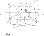
- the FIG. 4 shows an assembly 60, which has the cable channel 1, a cable 62 and a cable tie 64.
- the cable tie 64 includes a head 64, and a strap 66 connected at a first end to the head 64.
- the band 66 is intended to be pulled through an opening provided in the head 64, thus forming a loop.
- the cable 62 extends substantially in the longitudinal direction X-X of the cable channel 1 and is connected via the cable tie 64 to the bottom of the cable channel 1.
- the cable 62 is connected to the cable channel 1 via a second attachment hole 45.
- the cable tie 64 is connected to a tab 52 of a second attachment hole 45.
- the cable tie 64 forms a loop which tightly encloses the cable 62 and the fastening web 54 of the tab 52.
- the holding member 56 forms a stop for the cable tie 64 in the longitudinal direction by limiting a displacement of the cable tie 64 in the longitudinal direction.
- the holding part 56 in particular prevents slipping off the cable tie 64 from the fastening web 54.
- the cable 62 is connected by the cable tie 64 via first mounting holes 25 to the bottom 9 of the cable channel 1.
- the cable tie is guided by two transversely adjacent first mounting holes 25 and thus forms a loop around the cable 62 and the bottom web 26 between the holes 25.
- the assembly 60 may be advantageously used in a rail vehicle, for example.
- the cable channel 1 according to the invention is particularly advantageous, since it 27 by the provision of additional, wider connection holes a greater variability of the positioning of the dividers 21 in the transverse direction of the cable channel 1 as cable channels which only have first mounting holes 25, both for attachment of the dividers, as also serve to attach the cable.
- the positions of the separating webs 15 can be varied across the width of a respective, wide connecting hole 27, depending on the desired width of the cable compartments 13, so that a large number of possible compartment widths is created.
- the compartments 13 need not necessarily have a width which corresponds to an integer multiple of the distance between two adjacent first mounting holes 25, as is the case with known cable ducts.
- first mounting holes 25 free for the inclusion of cable ties. Furthermore, according to the invention, there is no risk that the connecting tabs 21 of the dividers overlap the first or second mounting holes 25, 45, because the communicating holes 27 extend in transverse rows between the transverse rows of first and second mounting holes 25, 45.
- the additional, second mounting holes 45 are also advantageous since they allow the cables to be tied to the cable channel 1 when only one side of the cable channel 1 is accessible, while it is necessary for fixing the cables by means of the first mounting holes that the cable channel 1 also accessible from outside to thread the cable ties through the mounting holes can.
- the second attachment holes 45 could optionally be made in a conduit 1 independently of the communication holes 27.
Landscapes
- Engineering & Computer Science (AREA)
- Architecture (AREA)
- Civil Engineering (AREA)
- Structural Engineering (AREA)
- Details Of Indoor Wiring (AREA)
- Supports For Pipes And Cables (AREA)
- Manufacturing Of Electric Cables (AREA)
Applications Claiming Priority (1)
| Application Number | Priority Date | Filing Date | Title |
|---|---|---|---|
| DE102017116679.3A DE102017116679A1 (de) | 2017-07-24 | 2017-07-24 | Kabelkanal |
Publications (2)
| Publication Number | Publication Date |
|---|---|
| EP3435501A1 true EP3435501A1 (fr) | 2019-01-30 |
| EP3435501B1 EP3435501B1 (fr) | 2022-12-28 |
Family
ID=63041875
Family Applications (1)
| Application Number | Title | Priority Date | Filing Date |
|---|---|---|---|
| EP18185188.2A Active EP3435501B1 (fr) | 2017-07-24 | 2018-07-24 | Canal à câbles |
Country Status (4)
| Country | Link |
|---|---|
| EP (1) | EP3435501B1 (fr) |
| DE (1) | DE102017116679A1 (fr) |
| ES (1) | ES2939888T3 (fr) |
| PL (1) | PL3435501T3 (fr) |
Cited By (2)
| Publication number | Priority date | Publication date | Assignee | Title |
|---|---|---|---|---|
| FR3115010A1 (fr) * | 2020-10-13 | 2022-04-15 | Speedinnov | Chemin de câblage pour véhicule de transport, notamment ferroviaire, caisse de véhicule et véhicule comprenant un tel chemin de câblage |
| WO2026027067A1 (fr) * | 2024-08-01 | 2026-02-05 | Siemens Mobility GmbH | Dispositif de fixation pour attaches de câbles |
Families Citing this family (1)
| Publication number | Priority date | Publication date | Assignee | Title |
|---|---|---|---|---|
| US20240258782A1 (en) * | 2023-01-27 | 2024-08-01 | The Boeing Company | Raceway assembly for cables |
Citations (7)
| Publication number | Priority date | Publication date | Assignee | Title |
|---|---|---|---|---|
| DE19726500A1 (de) * | 1996-07-08 | 1998-01-15 | Defem System Ab | Trennvorrichtung für eine Kabelbahn |
| WO1999010957A1 (fr) * | 1997-08-26 | 1999-03-04 | Øglænd System As | Perfectionnement de sections d'une echelle a cables ou de sections d'un chemin a cables, ou relatif a celles-ci |
| WO2009112754A2 (fr) * | 2008-02-26 | 2009-09-17 | Alstom Transport Sa | Dispositif de fixation d'une pluralité de câbles regroupés entre eux |
| FR2972235A1 (fr) * | 2011-03-01 | 2012-09-07 | Cts Cable Tray System | Dispositif pour la fixation d'une piece sur un troncon de chemin de cables et chemin de cables muni d'un tel dispositif |
| EP2709221A1 (fr) * | 2012-09-14 | 2014-03-19 | Zurecon Ag | Bande de câble |
| DE102013107181A1 (de) * | 2013-07-08 | 2015-01-08 | Bombardier Transportation Gmbh | Befestigungsvorrichtung für Kabel, sowie Verfahren zum Befestigen von Kabeln |
| EP2858189A1 (fr) * | 2013-10-07 | 2015-04-08 | Zurecon AG | Elément de séparation pour chemins de câbles et chemin de câbles |
-
2017
- 2017-07-24 DE DE102017116679.3A patent/DE102017116679A1/de active Pending
-
2018
- 2018-07-24 ES ES18185188T patent/ES2939888T3/es active Active
- 2018-07-24 PL PL18185188.2T patent/PL3435501T3/pl unknown
- 2018-07-24 EP EP18185188.2A patent/EP3435501B1/fr active Active
Patent Citations (7)
| Publication number | Priority date | Publication date | Assignee | Title |
|---|---|---|---|---|
| DE19726500A1 (de) * | 1996-07-08 | 1998-01-15 | Defem System Ab | Trennvorrichtung für eine Kabelbahn |
| WO1999010957A1 (fr) * | 1997-08-26 | 1999-03-04 | Øglænd System As | Perfectionnement de sections d'une echelle a cables ou de sections d'un chemin a cables, ou relatif a celles-ci |
| WO2009112754A2 (fr) * | 2008-02-26 | 2009-09-17 | Alstom Transport Sa | Dispositif de fixation d'une pluralité de câbles regroupés entre eux |
| FR2972235A1 (fr) * | 2011-03-01 | 2012-09-07 | Cts Cable Tray System | Dispositif pour la fixation d'une piece sur un troncon de chemin de cables et chemin de cables muni d'un tel dispositif |
| EP2709221A1 (fr) * | 2012-09-14 | 2014-03-19 | Zurecon Ag | Bande de câble |
| DE102013107181A1 (de) * | 2013-07-08 | 2015-01-08 | Bombardier Transportation Gmbh | Befestigungsvorrichtung für Kabel, sowie Verfahren zum Befestigen von Kabeln |
| EP2858189A1 (fr) * | 2013-10-07 | 2015-04-08 | Zurecon AG | Elément de séparation pour chemins de câbles et chemin de câbles |
Cited By (3)
| Publication number | Priority date | Publication date | Assignee | Title |
|---|---|---|---|---|
| FR3115010A1 (fr) * | 2020-10-13 | 2022-04-15 | Speedinnov | Chemin de câblage pour véhicule de transport, notamment ferroviaire, caisse de véhicule et véhicule comprenant un tel chemin de câblage |
| EP3984852A1 (fr) * | 2020-10-13 | 2022-04-20 | SpeedInnov | Chemin de câblage pour véhicule de transport, notamment ferroviaire, caisse de véhicule et véhicule comprenant un tel chemin de câblage |
| WO2026027067A1 (fr) * | 2024-08-01 | 2026-02-05 | Siemens Mobility GmbH | Dispositif de fixation pour attaches de câbles |
Also Published As
| Publication number | Publication date |
|---|---|
| EP3435501B1 (fr) | 2022-12-28 |
| DE102017116679A1 (de) | 2019-01-24 |
| PL3435501T3 (pl) | 2023-05-08 |
| ES2939888T3 (es) | 2023-04-27 |
Similar Documents
| Publication | Publication Date | Title |
|---|---|---|
| EP3447868B1 (fr) | Canal de câble à points de fixation estampés avec points de rupture prédéterminés et son procédé de fabrication | |
| DE19527757A1 (de) | Sicherheitseinrichtung für Verbinder | |
| EP3175523A1 (fr) | Dispositif de guidage | |
| EP3435501B1 (fr) | Canal à câbles | |
| DE202017107144U1 (de) | Set aus Steckverbinder und Halteelement sowie Steckverbinder und Halteelement hierzu | |
| DE202017100200U1 (de) | Trennsteg für Energieführungsketten | |
| EP4104265A1 (fr) | Système de chemin de câbles | |
| DE202019100430U1 (de) | Trennsteg, Quersteg und Querboden für Energieführungsketten | |
| EP3526490B2 (fr) | Maillon de chaîne pour une chaîne de transmission d'énergie | |
| DE202008002786U1 (de) | Kabelhalter für mehrsträngiges Kabel | |
| DE102016124609A1 (de) | Verteilerkasten zum Einbau in eine Wandöffnung | |
| AT522385B1 (de) | Umlenkvorrichtung | |
| DE29802727U1 (de) | Anschlußleiste und auf eine Anschlußleiste aufsteckbares Überspannungsschutzmagazin | |
| EP2273638A2 (fr) | Pince pour canaux de câble destinée à masquer des bords de coupe | |
| DE69413698T2 (de) | Kanalsystem aus Teilen wie Kanäle und Kupplungen für horizontale und vertikale Verzweigungen von Kabeln, Drähten oder dergleichen | |
| EP1587195A2 (fr) | Système de canalisation pour câble | |
| EP0446475A2 (fr) | Canal pour câbles, en particulier goulotte de paroi, canal pour appareillages ou similaires | |
| EP2639910B1 (fr) | Boîtier encastrable pour canaux d'intégration d'appareil et canal d'intégration d'appareils doté de celui-ci | |
| EP0862253A1 (fr) | Canalisation pour câbles, tel que canalisation pour installation électrique ou montage d'appareils | |
| EP2418746A2 (fr) | Boîtier d'appareillage pour appareils dýinstallation | |
| WO1998023879A2 (fr) | Jeu de pieces pour chainon adaptable a plusieurs utilisations | |
| EP0696098A1 (fr) | Dispositif de couplage pour canalisations de guidage de câbles | |
| DE102007044508A1 (de) | Kabelverbund | |
| DE10116165B4 (de) | Vorrichtung zur Herstellung von abgehängten Decken | |
| DE19546779C1 (de) | Grundelement mit Aufnahmeeinrichtungen |
Legal Events
| Date | Code | Title | Description |
|---|---|---|---|
| PUAI | Public reference made under article 153(3) epc to a published international application that has entered the european phase |
Free format text: ORIGINAL CODE: 0009012 |
|
| STAA | Information on the status of an ep patent application or granted ep patent |
Free format text: STATUS: THE APPLICATION HAS BEEN PUBLISHED |
|
| AK | Designated contracting states |
Kind code of ref document: A1 Designated state(s): AL AT BE BG CH CY CZ DE DK EE ES FI FR GB GR HR HU IE IS IT LI LT LU LV MC MK MT NL NO PL PT RO RS SE SI SK SM TR |
|
| AX | Request for extension of the european patent |
Extension state: BA ME |
|
| STAA | Information on the status of an ep patent application or granted ep patent |
Free format text: STATUS: REQUEST FOR EXAMINATION WAS MADE |
|
| 17P | Request for examination filed |
Effective date: 20190724 |
|
| RBV | Designated contracting states (corrected) |
Designated state(s): AL AT BE BG CH CY CZ DE DK EE ES FI FR GB GR HR HU IE IS IT LI LT LU LV MC MK MT NL NO PL PT RO RS SE SI SK SM TR |
|
| STAA | Information on the status of an ep patent application or granted ep patent |
Free format text: STATUS: EXAMINATION IS IN PROGRESS |
|
| 17Q | First examination report despatched |
Effective date: 20191106 |
|
| GRAP | Despatch of communication of intention to grant a patent |
Free format text: ORIGINAL CODE: EPIDOSNIGR1 |
|
| STAA | Information on the status of an ep patent application or granted ep patent |
Free format text: STATUS: GRANT OF PATENT IS INTENDED |
|
| INTG | Intention to grant announced |
Effective date: 20220720 |
|
| GRAS | Grant fee paid |
Free format text: ORIGINAL CODE: EPIDOSNIGR3 |
|
| GRAA | (expected) grant |
Free format text: ORIGINAL CODE: 0009210 |
|
| STAA | Information on the status of an ep patent application or granted ep patent |
Free format text: STATUS: THE PATENT HAS BEEN GRANTED |
|
| AK | Designated contracting states |
Kind code of ref document: B1 Designated state(s): AL AT BE BG CH CY CZ DE DK EE ES FI FR GB GR HR HU IE IS IT LI LT LU LV MC MK MT NL NO PL PT RO RS SE SI SK SM TR |
|
| REG | Reference to a national code |
Ref country code: GB Ref legal event code: FG4D Free format text: NOT ENGLISH |
|
| REG | Reference to a national code |
Ref country code: CH Ref legal event code: EP |
|
| REG | Reference to a national code |
Ref country code: DE Ref legal event code: R096 Ref document number: 502018011297 Country of ref document: DE |
|
| REG | Reference to a national code |
Ref country code: AT Ref legal event code: REF Ref document number: 1541062 Country of ref document: AT Kind code of ref document: T Effective date: 20230115 |
|
| REG | Reference to a national code |
Ref country code: IE Ref legal event code: FG4D Free format text: LANGUAGE OF EP DOCUMENT: GERMAN |
|
| REG | Reference to a national code |
Ref country code: LT Ref legal event code: MG9D |
|
| REG | Reference to a national code |
Ref country code: ES Ref legal event code: FG2A Ref document number: 2939888 Country of ref document: ES Kind code of ref document: T3 Effective date: 20230427 |
|
| PG25 | Lapsed in a contracting state [announced via postgrant information from national office to epo] |
Ref country code: SE Free format text: LAPSE BECAUSE OF FAILURE TO SUBMIT A TRANSLATION OF THE DESCRIPTION OR TO PAY THE FEE WITHIN THE PRESCRIBED TIME-LIMIT Effective date: 20221228 Ref country code: NO Free format text: LAPSE BECAUSE OF FAILURE TO SUBMIT A TRANSLATION OF THE DESCRIPTION OR TO PAY THE FEE WITHIN THE PRESCRIBED TIME-LIMIT Effective date: 20230328 Ref country code: LT Free format text: LAPSE BECAUSE OF FAILURE TO SUBMIT A TRANSLATION OF THE DESCRIPTION OR TO PAY THE FEE WITHIN THE PRESCRIBED TIME-LIMIT Effective date: 20221228 Ref country code: FI Free format text: LAPSE BECAUSE OF FAILURE TO SUBMIT A TRANSLATION OF THE DESCRIPTION OR TO PAY THE FEE WITHIN THE PRESCRIBED TIME-LIMIT Effective date: 20221228 |
|
| REG | Reference to a national code |
Ref country code: NL Ref legal event code: MP Effective date: 20221228 |
|
| PG25 | Lapsed in a contracting state [announced via postgrant information from national office to epo] |
Ref country code: RS Free format text: LAPSE BECAUSE OF FAILURE TO SUBMIT A TRANSLATION OF THE DESCRIPTION OR TO PAY THE FEE WITHIN THE PRESCRIBED TIME-LIMIT Effective date: 20221228 Ref country code: LV Free format text: LAPSE BECAUSE OF FAILURE TO SUBMIT A TRANSLATION OF THE DESCRIPTION OR TO PAY THE FEE WITHIN THE PRESCRIBED TIME-LIMIT Effective date: 20221228 Ref country code: HR Free format text: LAPSE BECAUSE OF FAILURE TO SUBMIT A TRANSLATION OF THE DESCRIPTION OR TO PAY THE FEE WITHIN THE PRESCRIBED TIME-LIMIT Effective date: 20221228 Ref country code: GR Free format text: LAPSE BECAUSE OF FAILURE TO SUBMIT A TRANSLATION OF THE DESCRIPTION OR TO PAY THE FEE WITHIN THE PRESCRIBED TIME-LIMIT Effective date: 20230329 |
|
| PG25 | Lapsed in a contracting state [announced via postgrant information from national office to epo] |
Ref country code: NL Free format text: LAPSE BECAUSE OF FAILURE TO SUBMIT A TRANSLATION OF THE DESCRIPTION OR TO PAY THE FEE WITHIN THE PRESCRIBED TIME-LIMIT Effective date: 20221228 |
|
| PG25 | Lapsed in a contracting state [announced via postgrant information from national office to epo] |
Ref country code: SM Free format text: LAPSE BECAUSE OF FAILURE TO SUBMIT A TRANSLATION OF THE DESCRIPTION OR TO PAY THE FEE WITHIN THE PRESCRIBED TIME-LIMIT Effective date: 20221228 Ref country code: PT Free format text: LAPSE BECAUSE OF FAILURE TO SUBMIT A TRANSLATION OF THE DESCRIPTION OR TO PAY THE FEE WITHIN THE PRESCRIBED TIME-LIMIT Effective date: 20230428 Ref country code: EE Free format text: LAPSE BECAUSE OF FAILURE TO SUBMIT A TRANSLATION OF THE DESCRIPTION OR TO PAY THE FEE WITHIN THE PRESCRIBED TIME-LIMIT Effective date: 20221228 Ref country code: CZ Free format text: LAPSE BECAUSE OF FAILURE TO SUBMIT A TRANSLATION OF THE DESCRIPTION OR TO PAY THE FEE WITHIN THE PRESCRIBED TIME-LIMIT Effective date: 20221228 Ref country code: RO Free format text: LAPSE BECAUSE OF FAILURE TO SUBMIT A TRANSLATION OF THE DESCRIPTION OR TO PAY THE FEE WITHIN THE PRESCRIBED TIME-LIMIT Effective date: 20221228 |
|
| PG25 | Lapsed in a contracting state [announced via postgrant information from national office to epo] |
Ref country code: SK Free format text: LAPSE BECAUSE OF FAILURE TO SUBMIT A TRANSLATION OF THE DESCRIPTION OR TO PAY THE FEE WITHIN THE PRESCRIBED TIME-LIMIT Effective date: 20221228 Ref country code: IS Free format text: LAPSE BECAUSE OF FAILURE TO SUBMIT A TRANSLATION OF THE DESCRIPTION OR TO PAY THE FEE WITHIN THE PRESCRIBED TIME-LIMIT Effective date: 20230428 Ref country code: AL Free format text: LAPSE BECAUSE OF FAILURE TO SUBMIT A TRANSLATION OF THE DESCRIPTION OR TO PAY THE FEE WITHIN THE PRESCRIBED TIME-LIMIT Effective date: 20221228 |
|
| P01 | Opt-out of the competence of the unified patent court (upc) registered |
Effective date: 20230823 |
|
| REG | Reference to a national code |
Ref country code: DE Ref legal event code: R097 Ref document number: 502018011297 Country of ref document: DE |
|
| RAP2 | Party data changed (patent owner data changed or rights of a patent transferred) |
Owner name: ALSTOM HOLDINGS |
|
| PG25 | Lapsed in a contracting state [announced via postgrant information from national office to epo] |
Ref country code: DK Free format text: LAPSE BECAUSE OF FAILURE TO SUBMIT A TRANSLATION OF THE DESCRIPTION OR TO PAY THE FEE WITHIN THE PRESCRIBED TIME-LIMIT Effective date: 20221228 |
|
| PLBE | No opposition filed within time limit |
Free format text: ORIGINAL CODE: 0009261 |
|
| STAA | Information on the status of an ep patent application or granted ep patent |
Free format text: STATUS: NO OPPOSITION FILED WITHIN TIME LIMIT |
|
| 26N | No opposition filed |
Effective date: 20230929 |
|
| PG25 | Lapsed in a contracting state [announced via postgrant information from national office to epo] |
Ref country code: SI Free format text: LAPSE BECAUSE OF FAILURE TO SUBMIT A TRANSLATION OF THE DESCRIPTION OR TO PAY THE FEE WITHIN THE PRESCRIBED TIME-LIMIT Effective date: 20221228 |
|
| PG25 | Lapsed in a contracting state [announced via postgrant information from national office to epo] |
Ref country code: MC Free format text: LAPSE BECAUSE OF FAILURE TO SUBMIT A TRANSLATION OF THE DESCRIPTION OR TO PAY THE FEE WITHIN THE PRESCRIBED TIME-LIMIT Effective date: 20221228 |
|
| PG25 | Lapsed in a contracting state [announced via postgrant information from national office to epo] |
Ref country code: MC Free format text: LAPSE BECAUSE OF FAILURE TO SUBMIT A TRANSLATION OF THE DESCRIPTION OR TO PAY THE FEE WITHIN THE PRESCRIBED TIME-LIMIT Effective date: 20221228 |
|
| REG | Reference to a national code |
Ref country code: CH Ref legal event code: PL |
|
| REG | Reference to a national code |
Ref country code: BE Ref legal event code: MM Effective date: 20230731 |
|
| PG25 | Lapsed in a contracting state [announced via postgrant information from national office to epo] |
Ref country code: LU Free format text: LAPSE BECAUSE OF NON-PAYMENT OF DUE FEES Effective date: 20230724 |
|
| GBPC | Gb: european patent ceased through non-payment of renewal fee |
Effective date: 20230724 |
|
| PG25 | Lapsed in a contracting state [announced via postgrant information from national office to epo] |
Ref country code: LU Free format text: LAPSE BECAUSE OF NON-PAYMENT OF DUE FEES Effective date: 20230724 |
|
| REG | Reference to a national code |
Ref country code: IE Ref legal event code: MM4A |
|
| PG25 | Lapsed in a contracting state [announced via postgrant information from national office to epo] |
Ref country code: GB Free format text: LAPSE BECAUSE OF NON-PAYMENT OF DUE FEES Effective date: 20230724 Ref country code: CH Free format text: LAPSE BECAUSE OF NON-PAYMENT OF DUE FEES Effective date: 20230731 |
|
| PG25 | Lapsed in a contracting state [announced via postgrant information from national office to epo] |
Ref country code: BE Free format text: LAPSE BECAUSE OF NON-PAYMENT OF DUE FEES Effective date: 20230731 |
|
| PG25 | Lapsed in a contracting state [announced via postgrant information from national office to epo] |
Ref country code: IE Free format text: LAPSE BECAUSE OF NON-PAYMENT OF DUE FEES Effective date: 20230724 |
|
| PG25 | Lapsed in a contracting state [announced via postgrant information from national office to epo] |
Ref country code: IE Free format text: LAPSE BECAUSE OF NON-PAYMENT OF DUE FEES Effective date: 20230724 |
|
| REG | Reference to a national code |
Ref country code: AT Ref legal event code: MM01 Ref document number: 1541062 Country of ref document: AT Kind code of ref document: T Effective date: 20230724 |
|
| PG25 | Lapsed in a contracting state [announced via postgrant information from national office to epo] |
Ref country code: AT Free format text: LAPSE BECAUSE OF NON-PAYMENT OF DUE FEES Effective date: 20230724 |
|
| PG25 | Lapsed in a contracting state [announced via postgrant information from national office to epo] |
Ref country code: AT Free format text: LAPSE BECAUSE OF NON-PAYMENT OF DUE FEES Effective date: 20230724 |
|
| PG25 | Lapsed in a contracting state [announced via postgrant information from national office to epo] |
Ref country code: BG Free format text: LAPSE BECAUSE OF FAILURE TO SUBMIT A TRANSLATION OF THE DESCRIPTION OR TO PAY THE FEE WITHIN THE PRESCRIBED TIME-LIMIT Effective date: 20221228 |
|
| PG25 | Lapsed in a contracting state [announced via postgrant information from national office to epo] |
Ref country code: BG Free format text: LAPSE BECAUSE OF FAILURE TO SUBMIT A TRANSLATION OF THE DESCRIPTION OR TO PAY THE FEE WITHIN THE PRESCRIBED TIME-LIMIT Effective date: 20221228 |
|
| PG25 | Lapsed in a contracting state [announced via postgrant information from national office to epo] |
Ref country code: CY Free format text: LAPSE BECAUSE OF FAILURE TO SUBMIT A TRANSLATION OF THE DESCRIPTION OR TO PAY THE FEE WITHIN THE PRESCRIBED TIME-LIMIT; INVALID AB INITIO Effective date: 20180724 |
|
| PG25 | Lapsed in a contracting state [announced via postgrant information from national office to epo] |
Ref country code: HU Free format text: LAPSE BECAUSE OF FAILURE TO SUBMIT A TRANSLATION OF THE DESCRIPTION OR TO PAY THE FEE WITHIN THE PRESCRIBED TIME-LIMIT; INVALID AB INITIO Effective date: 20180724 |
|
| PGFP | Annual fee paid to national office [announced via postgrant information from national office to epo] |
Ref country code: ES Payment date: 20250826 Year of fee payment: 8 |
|
| PGFP | Annual fee paid to national office [announced via postgrant information from national office to epo] |
Ref country code: DE Payment date: 20250722 Year of fee payment: 8 |
|
| PGFP | Annual fee paid to national office [announced via postgrant information from national office to epo] |
Ref country code: PL Payment date: 20250711 Year of fee payment: 8 Ref country code: IT Payment date: 20250724 Year of fee payment: 8 |
|
| PGFP | Annual fee paid to national office [announced via postgrant information from national office to epo] |
Ref country code: FR Payment date: 20250725 Year of fee payment: 8 |
|
| PG25 | Lapsed in a contracting state [announced via postgrant information from national office to epo] |
Ref country code: TR Free format text: LAPSE BECAUSE OF FAILURE TO SUBMIT A TRANSLATION OF THE DESCRIPTION OR TO PAY THE FEE WITHIN THE PRESCRIBED TIME-LIMIT Effective date: 20221228 |