EP3436208B1 - Procédé de fabrication d'un corps moulé comportant un moyeu et dispositif permettant de mettre en oeuvre un tel procédé - Google Patents
Procédé de fabrication d'un corps moulé comportant un moyeu et dispositif permettant de mettre en oeuvre un tel procédé Download PDFInfo
- Publication number
- EP3436208B1 EP3436208B1 EP17714679.2A EP17714679A EP3436208B1 EP 3436208 B1 EP3436208 B1 EP 3436208B1 EP 17714679 A EP17714679 A EP 17714679A EP 3436208 B1 EP3436208 B1 EP 3436208B1
- Authority
- EP
- European Patent Office
- Prior art keywords
- contour
- raceways
- hub
- segments
- tool
- Prior art date
- Legal status (The legal status is an assumption and is not a legal conclusion. Google has not performed a legal analysis and makes no representation as to the accuracy of the status listed.)
- Active
Links
Images


Classifications
-
- B—PERFORMING OPERATIONS; TRANSPORTING
- B21—MECHANICAL METAL-WORKING WITHOUT ESSENTIALLY REMOVING MATERIAL; PUNCHING METAL
- B21D—WORKING OR PROCESSING OF SHEET METAL OR METAL TUBES, RODS OR PROFILES WITHOUT ESSENTIALLY REMOVING MATERIAL; PUNCHING METAL
- B21D22/00—Shaping without cutting, by stamping, spinning, or deep-drawing
- B21D22/14—Spinning
- B21D22/16—Spinning over shaping mandrels or formers
-
- B—PERFORMING OPERATIONS; TRANSPORTING
- B21—MECHANICAL METAL-WORKING WITHOUT ESSENTIALLY REMOVING MATERIAL; PUNCHING METAL
- B21D—WORKING OR PROCESSING OF SHEET METAL OR METAL TUBES, RODS OR PROFILES WITHOUT ESSENTIALLY REMOVING MATERIAL; PUNCHING METAL
- B21D53/00—Making other particular articles
- B21D53/10—Making other particular articles parts of bearings; sleeves; valve seats or the like
- B21D53/12—Making other particular articles parts of bearings; sleeves; valve seats or the like cages for bearings
-
- F—MECHANICAL ENGINEERING; LIGHTING; HEATING; WEAPONS; BLASTING
- F16—ENGINEERING ELEMENTS AND UNITS; GENERAL MEASURES FOR PRODUCING AND MAINTAINING EFFECTIVE FUNCTIONING OF MACHINES OR INSTALLATIONS; THERMAL INSULATION IN GENERAL
- F16D—COUPLINGS FOR TRANSMITTING ROTATION; CLUTCHES; BRAKES
- F16D3/00—Yielding couplings, i.e. with means permitting movement between the connected parts during the drive
- F16D3/16—Universal joints in which flexibility is produced by means of pivots or sliding or rolling connecting parts
- F16D3/20—Universal joints in which flexibility is produced by means of pivots or sliding or rolling connecting parts one coupling part entering a sleeve of the other coupling part and connected thereto by sliding or rolling members
- F16D3/22—Universal joints in which flexibility is produced by means of pivots or sliding or rolling connecting parts one coupling part entering a sleeve of the other coupling part and connected thereto by sliding or rolling members the rolling members being balls, rollers, or the like, guided in grooves or sockets in both coupling parts
- F16D3/223—Universal joints in which flexibility is produced by means of pivots or sliding or rolling connecting parts one coupling part entering a sleeve of the other coupling part and connected thereto by sliding or rolling members the rolling members being balls, rollers, or the like, guided in grooves or sockets in both coupling parts the rolling members being guided in grooves in both coupling parts
-
- F—MECHANICAL ENGINEERING; LIGHTING; HEATING; WEAPONS; BLASTING
- F16—ENGINEERING ELEMENTS AND UNITS; GENERAL MEASURES FOR PRODUCING AND MAINTAINING EFFECTIVE FUNCTIONING OF MACHINES OR INSTALLATIONS; THERMAL INSULATION IN GENERAL
- F16D—COUPLINGS FOR TRANSMITTING ROTATION; CLUTCHES; BRAKES
- F16D2250/00—Manufacturing; Assembly
- F16D2250/0023—Shaping by pressure
Definitions
- the invention relates to a method for producing a molded body having a hub and an axially adjoining bell-shaped lower part according to the preamble of claim 1.
- Shaped bodies of this type are used, in particular, as axle or pivot pins and are part of a connecting joint in order to transmit torques on components that are at an angle to one another, primarily shafts.
- a method corresponding to the genus is for example in the DE 10 2013 101 555 B3 disclosed.
- This inner contour consists of circumferentially alternately arranged ball races and cage tracks which are concavely curved in the axial direction of the shaped body, the ball tracks being formed deeper than the cage tracks.
- Characteristic is the introduction of the inner contour into a bulbous area of the lower part, which is constricted to a certain extent on its side opposite the hub. This means that the clear diameter in this area is smaller than the diameter in the apex of the bulbous area. This constriction, in continuation of the bulbous area, is followed by a conically widening section as an apron, which, in deviation from this, can also be oriented radially outwards.
- the bell-shaped lower part is produced by pressing using a suitable pressing tool or by pressing using a pressure roller, while the subsequent inner contouring is carried out by a pressure roller contoured on the outside, with which the bulbous region of the lower part is pressed against a multi-part inner contour tool having contour segments.
- the invention has for its object to develop a method of the generic type so that the dimensional accuracy of the molded body and its usability is improved.
- the essence of the invention is to bring both the hub and the bell-shaped lower part into a preform by means of at least one pressure roller, in which the inner contours, ie the cage and ball raceways, are partially formed with regard to their depth.
- the outer lateral surface of the lower part remains smooth during the preforming of the lower part by means of the at least one pressure roller
- the outer lateral surface is likewise shaped according to the curvature of the inner contour according to the curvature of the inner contour during the final shaping, according to the invention, whereby the concave curvatures form both in the axial direction as well as across the ball raceways and the cage tracks as convex curvatures on the outer surface.
- the material is heated to form the hub and / or to produce the preform and / or the final molding, preferably to a temperature of approximately 400 ° to 1000 °, preferably approximately 600 ° C to 700 ° C.
- the molded body can be manufactured much more quickly, with the hub optionally being designed as a hollow or solid body.
- a device for carrying out the method has a first, rotatable inner contour tool for forming the preform, with radially movable, separate contour segments, each of which is assigned to a ball raceway and a cage raceway and which in the functional position lie against one another without a gap.
- contour segments for the formation of the preform are identical to those for the formation of the endform and only differ in their dimensional configuration.
- the structure of the device is comparable for both applications.
- the second inner contour tool is held against rotation.
- the contour segments In order to remove the lower part, whether as a preform or as an end molding, from the contour tool, the contour segments, as mentioned, can be moved radially inward, that is to say towards the axis of rotation, by means of a positive guide.
- the contour segments are held on a conical ring which tapers towards the hub and which has sliding surfaces on the outside, on which the contour segments are supported.
- This cone ring is axially displaceable relative to the contour segments, each contour segment having an undercut longitudinal groove in which a cap screw or a sliding block connected to the cone ring is guided.
- the inclination of the guide surfaces of the conical ring, on which the contour segments for the ball raceways rest, is flatter than the guide surfaces on which the cage tracks are located for a free, unimpeded radial movement of the adjacent contour segments assigned to the cage tracks and the ball raceways, in particular that of the second contour tool support assigned contour segments.
- contour segments can be moved radially to the axis of rotation of the molded body to such an extent that the lower part, whether as a preform or as an end molding, also with the smallest clear diameter in the part delimiting the bulbous area, which is followed by an outwardly directed conical skirt Can run over contour segments.
- the device is also characterized by its high stability and concentricity due to the formation of the upper end of the guide column near the hub, so that the forces occurring during the deformation of the blank towards a finished shaped body can be absorbed without problems.
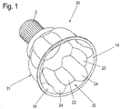
- FIG. 1 An essentially rotationally symmetrical shaped body 30 is shown, with a hub 2 and an adjoining, non-cutting molded lower part 31.
- Such a shaped body 30, which is already known from the prior art, has in its lower part 31 an inner contour 32 consisting of ball raceways 24, between each of which a cage raceway 23 is formed, the ball raceways 24 and the cage raceways 23 being uniform over the circumference of the lower part 31 are distributed.
- the cage tracks 23 and the ball raceways 24 are concavely curved in the axial direction with respect to an axis X, and also transversely thereto.
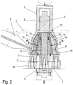
- the ball raceways 24 project into a lower end region of the lower part opposite the hub 2, while the cage paths 23 extend shorter than the ball raceways 24 into the region of an apron 14, which in the example, such as in particular the Figure 2 reproduces very clearly, widens conically outwards. It is also conceivable to shape the apron 14 into a radial orientation.
- the round blank 3 is pressed by an attachment 1 as a clamping element against an axially fixed guide column 8 held in a base plate 12, which at the same time takes over the centering function.
- the guide column 8 has a support plate 27 on its end facing the hub, on which the round blank 3 is supported.
- the guide column 8 is part of a first inner contour tool which also has a conical ring 9 which is held on the guide column 8 in a manner which prevents it from rotating but is axially displaceable.
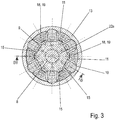
- the anti-rotation is done as in Figure 3 to recognize, preferably by a spline 22A, also referred to as a spline connection, between the guide column 8 and the cone ring 9 in order to be able to absorb the high torque occurring in this step.
- the planar region of the circular blank 3, which adjoins the hub 2 radially, is pressed against the first inner contour tool, i.e. pressed against contour segments 10, 11 of the first inner contour tool, the pressure roller 4 being fed radially and axially.
- the first inner contour tool rotates with the circular blank 3.
- a preform 13 is thereby created, the outer lateral surface of which is contoured only in the axial direction, as shown in FIG Figure 2 .
- cage tracks 23 and ball raceways 24 are preformed by the contour segments 10, 11, that is to say only in terms of their axial contour course, but not in terms of their width and depth in accordance with the final molding, which is particularly evident in FIG Figure 3 can be seen.
- the cone ring 9 is moved downward in the direction of the arrow, into a position corresponding to the broken line illustration, the cone ring 9 being via axially movable pressure stamps 7 is connected to a pressure plate 5.
- the guide column 8 on the other hand, is fastened in a base plate 12, which is held stationary and on which a support ring 6 is fastened, which serves as an abutment for the contour segments 10, 11 when the cone ring 9 is down, i.e. is pulled in the direction facing away from the hub 2.
- the contour segments 10, 11 are moved radially in the direction of the guide column 8, for which purpose a sliding block in guide surfaces 27 of the cone ring 9, on which the contour segments 10, 11 are slidably mounted 18 is attached, which engages in a link guide 19 of the respective contour segment 10, 11.
- This sliding block 18 can consist, for example, of a cap screw.
- the preform 13 is further processed into a final molding, namely the lower part 30.
- This step is in the Figures 4 and 5 displayed.
- the structure of the second inner contour tool is comparable to that of the first inner contour tool for forming the preform 13.
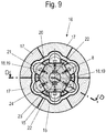
- contour segments 20, 21 are used which differ in their dimensions from the contour segments 10, 11 of the first inner contour tool, in such a way that Ball raceways 24 and cage tracks 23 get their final shape.
- radially deliverable die parts 17 are provided on the outer lateral surface of the preform 13, which are segment-like components of a die 16 and which are pressed onto the outer lateral surface of the now non-rotating preform 13, the die parts 17, one of which is a ball raceway 24 is assigned, has a concave shape which is adapted to the convex shape of the contour segment 21, so that there is a corresponding outer contour of the final part forming the lower part 31.
- the contour segments 20, 21 are held in a non-functional position, that is to say the conical ring 9 is brought into an end position displaced in relation to the guide column 8 in the direction of the base plate, with forced radial movement inwards to the guide column 8 towards the contour segments 20, 21.
- the cone ring 9 is displaced in the direction of the hub 2 or the molded support plate 27 of the guide column 8, and the contour segments 20, 21 in move an end position in which they lie against each other without gaps or almost without gaps.
- the planar region of the circular blank 3 adjoining the hub 2 is pressed against the first inner contour tool, ie against contour segments 10 ', 11 of the first inner contour tool, the pressure roller 4 being advanced radially and axially.
- the shape of the contour segments 10 ' is here such that the radius of the outer surface of the contour segments 10' never increases axially upwards, i.e. counter to the direction of the final shape, axially to the axis of rotation of the guide column 8, but is designed to decrease or remain constant upwards, so that after it has taken place Pressing the blank 3 against the first inner contour tool of the preform 13 relative to the contour tool can be easily removed.
- a preform 13 is thereby created, the outer lateral surface of which is contoured only in the axial direction, as shown in FIG Figure 2 ,
- the blank or the preform can, as already stated, be heated. In order to increase the service life of the tools involved in the deformation, they can be cooled, and corresponding cooling channels can be provided.
Landscapes
- Engineering & Computer Science (AREA)
- Mechanical Engineering (AREA)
- General Engineering & Computer Science (AREA)
- Rolling Contact Bearings (AREA)
- Forging (AREA)
Claims (15)
- Procédé pour la fabrication d'un corps mis en forme (30) en métal, en particulier en acier, présentant un moyeu (2) et une partie inférieure (31) en forme de cloche s'y raccordant, dans lequel est formé par formage sans enlèvement de matière dans la partie inférieure (31), dans une zone convexe renflée, un contour intérieur composé de pistes de cage (23) et de pistes de roulement à billes (24) concaves dans le sens de l'axe et disposées alternativement sur la circonférence pour recevoir des corps de roulement, la profondeur des pistes de cage (23) étant inférieure à celle des pistes de roulement à billes (24), caractérisé en ce qu'il comprend les étapes de procédé suivantes, exécutées successivement :a) formage du moyeu (2) au moyen d'au moins un rouleau presseur (4) rotatif à partir d'un flan circulaire (3) en rotation en réduisant l'épaisseur de celui-ci,b) pressage d'une zone plane du flan circulaire (3) se raccordant au moyeu (2) dans le sens radial pour former une ébauche (13) de la partie inférieure (31) au moyen d'au moins un rouleau presseur (4) déplacé dans le sens axial et radial sur des segments de contour (10, 10', 11) d'un premier outil de contour intérieur en rotation en formant partiellement le contour intérieur, etc) pressage de l'ébauche (13) immobile par une matrice (16) formée de parties de matrice (17) contre des segments de contour (20, 21) d'un deuxième outil de contour intérieur en formant complètement les pistes de cage (23) et les pistes de roulement à billes (24).
- Procédé selon la revendication 1, caractérisé en ce qu'après la formation partielle et après la formation complète du contour intérieur correspondant, les segments de contour (10, 11, 20, 21) sont déplacés dans le sens radial vers l'axe (X) en dehors de la zone de recouvrement avec la partie inférieure (31).
- Procédé selon la revendication 1 ou 2, caractérisé en ce que le flan circulaire (3) est chauffé pour former le moyeu (2) et/ou former l'ébauche (13) et/ou l'ébauche (13) pour la formation finale de la partie inférieure (31) à une température d'environ 400 °C à 1000 °C, de préférence de 400 °C à 600 °C.
- Dispositif pour la mise en œuvre du procédé selon l'une des revendications principales, caractérisé en ce qu'il comprend un premier outil de contour intérieur rotatif et un deuxième outil de contour intérieur fixe qui présentent chacun, pour matricer les pistes de roulement à billes (24) et les pistes de cage (23), des segments de contour (10, 10', 11, 20, 21) séparés et capables d'un mouvement forcé, et le premier outil de contour est associé à au moins un rouleau presseur déplaçable dans le sens radial et axial et le deuxième outil de contour à une matrice (16) pouvant être approchée dans le sens radial, les segments de contour (10, 10', 11) du premier outil de contour présentant des parties convexes pour former les pistes de roulement à billes (24) et les pistes de cage (23) de l'ébauche (13) et les segments de contour (20, 21) du deuxième outil de contour des parties convexes pour former les pistes de roulement à billes (24) et les pistes de cage (23) des partie inférieures (31) formant une ébauche finale et un élément de serrage étant prévu au moins au niveau du premier outil de contour pour le serrage immobile en rotation du flan circulaire (3) pourvu d'un moyeu (2).
- Dispositif selon la revendication 4, caractérisé en ce que les segments de contour (10, 10', 11, 20, 21) reposent les uns contre les autres sans interstice dans la position de fonctionnement.
- Dispositif selon la revendication 4 ou 5, caractérisé en ce que les segments de contour (10, 11, 20, 21) reposent sur une bague conique (9) qui se resserre en direction du moyeu (2), laquelle bague conique (9) est mobile dans le sens axial.
- Dispositif selon l'une des revendications 4 à 6, caractérisé en ce que les segments de contour (10, 11, 20, 21) et des surfaces de guidage (15) de la bague conique (9) présentent des éléments de guidage qui se correspondent l'un à l'autre, dont l'un est conformé comme un coulisseau (18) et l'autre comme une gorge longitudinale (19) en contre-dépouille.
- Dispositif selon la revendication 4 ou 5, caractérisé en ce que le segment de contour (10') du premier outil de contour est conçu d'un seul tenant avec la bague conique (9) pour former les pistes de roulement à billes (24).
- Dispositif selon l'une des revendications 4 à 8, caractérisé en ce que la bague conique (9) est retenue sur un montant de guidage (8) avec possibilité de translation axiale et immobilisée en rotation.
- Dispositif selon l'une des revendications 4 à 8, caractérisé en ce que le montant de guidage (8) présente sur son côté orienté vers le moyeu (2) un plateau d'appui et de centrage (27).
- Dispositif selon l'une des revendications 4 à 9, caractérisé en ce que les surfaces de guidage (15) conformées comme un biseau dans le sens de l'axe des segments de contour (20, 21), au moins, du deuxième outil de contour sont différentes par leur inclinaison.
- Dispositif selon l'une des revendications 4 à 10, caractérisé en ce que l'angle d'inclinaison des segments de contour (21) formant la piste de roulement à billes (24) par rapport à l'axe (X) est plus grand que celui des segments de contour (20) formant les pistes de cage (23).
- Dispositif selon l'une des revendications 4 à 11, caractérisé en ce que la matrice (16) se compose de plusieurs parties de matrice (17) qui peuvent être approchées dans le sens radial.
- Dispositif selon l'une des revendications 4 à 12, caractérisé en ce que chaque segment de contour (21) est associé à une partie de matrice (17).
- Dispositif selon l'une des revendications 4 à 13, caractérisé en ce que les segments de contour (10, 11, 20, 21) sont retenus avec une fixation axiale par rapport à la bague conique (9).
Priority Applications (1)
| Application Number | Priority Date | Filing Date | Title |
|---|---|---|---|
| PL17714679T PL3436208T3 (pl) | 2016-03-30 | 2017-03-27 | Sposób wytwarzania korpusu formowanego zawierającego piastę oraz urządzenie do realizacji tego sposobu |
Applications Claiming Priority (2)
| Application Number | Priority Date | Filing Date | Title |
|---|---|---|---|
| DE102016105771.1A DE102016105771A1 (de) | 2016-03-30 | 2016-03-30 | Verfahren zur Herstellung eines eine Nabe aufweisenden Formkörpers sowie Vorrichtung zur Durchführung des Verfahrens |
| PCT/EP2017/057170 WO2017167678A1 (fr) | 2016-03-30 | 2017-03-27 | Procédé de fabrication d'un corps moulé comportant un moyeu et dispositif permettant de mettre en œuvre un tel procédé |
Publications (2)
| Publication Number | Publication Date |
|---|---|
| EP3436208A1 EP3436208A1 (fr) | 2019-02-06 |
| EP3436208B1 true EP3436208B1 (fr) | 2020-02-26 |
Family
ID=58461290
Family Applications (1)
| Application Number | Title | Priority Date | Filing Date |
|---|---|---|---|
| EP17714679.2A Active EP3436208B1 (fr) | 2016-03-30 | 2017-03-27 | Procédé de fabrication d'un corps moulé comportant un moyeu et dispositif permettant de mettre en oeuvre un tel procédé |
Country Status (9)
| Country | Link |
|---|---|
| US (1) | US11020784B2 (fr) |
| EP (1) | EP3436208B1 (fr) |
| KR (1) | KR102310579B1 (fr) |
| CN (1) | CN109153064B (fr) |
| DE (1) | DE102016105771A1 (fr) |
| ES (1) | ES2792103T3 (fr) |
| MX (1) | MX378976B (fr) |
| PL (1) | PL3436208T3 (fr) |
| WO (1) | WO2017167678A1 (fr) |
Families Citing this family (5)
| Publication number | Priority date | Publication date | Assignee | Title |
|---|---|---|---|---|
| JP6181219B1 (ja) * | 2016-02-16 | 2017-08-16 | Ntn株式会社 | 等速自在継手の外側継手部材の鍛造方法 |
| CN116621434B (zh) * | 2023-06-05 | 2026-04-10 | 常熟市伟恒模具铸造有限公司 | 一种具有异形模底的玻璃杯成型模具 |
| CN117086182B (zh) * | 2023-10-16 | 2023-12-22 | 河北中泊防爆工具集团股份有限公司 | 一种生产无缝防爆容器用的旋压装置及旋压方法 |
| CN117428098B (zh) * | 2023-12-20 | 2024-03-05 | 成都天科航空制造股份有限公司 | 一种管件旋压加工装置及加工方法 |
| CN119319163B (zh) * | 2024-12-18 | 2025-05-13 | 苏州轻装智能制造科技有限公司 | 一种便于定位的旋压机 |
Family Cites Families (19)
| Publication number | Priority date | Publication date | Assignee | Title |
|---|---|---|---|---|
| US2086488A (en) * | 1933-12-11 | 1937-07-06 | Kelsey Hayes Wheel Co | Method of forming brake drums |
| JPS5134381B2 (fr) * | 1971-08-11 | 1976-09-25 | ||
| DE3712301C2 (de) * | 1987-04-10 | 1994-04-28 | Loehr & Bromkamp Gmbh | Preßwerkzeug |
| JPH01104441A (ja) * | 1987-07-03 | 1989-04-21 | Aida Eng Ltd | 等速ジョイント及びその類似物の製造装置 |
| JP2728684B2 (ja) * | 1988-07-14 | 1998-03-18 | エヌティエヌ株式会社 | 等速ジョイント外輪の成形装置 |
| JPH10244344A (ja) | 1997-02-28 | 1998-09-14 | Unisia Jecs Corp | カップ状ソケット部材の成形装置 |
| JPH11247877A (ja) * | 1998-02-27 | 1999-09-14 | Ntn Corp | 等速ジョイントおよびその外輪の成形方法 |
| ATE507091T1 (de) * | 2001-03-29 | 2011-05-15 | Ntn Toyo Bearing Co Ltd | Lagervorrichtung für antriebsrad |
| AU2002361123A1 (en) * | 2001-12-26 | 2003-07-15 | Showa Denko K.K. | Method for manufacturing universal joint yoke, forging die and preform |
| AU2003209066A1 (en) * | 2002-03-05 | 2003-09-22 | Metal Forming And Coining Corporation | Annulus gear and drive shell |
| ITMI20061839A1 (it) * | 2005-10-05 | 2007-04-06 | Shaft Form Engineering Gmbh | Disposizione di giunto |
| JP2007289989A (ja) * | 2006-04-24 | 2007-11-08 | Jatco Ltd | 増肉した曲げ部を有する物品の製造方法及びその製造装置 |
| DE102006039656B4 (de) * | 2006-08-24 | 2008-12-18 | Leifeld Metal Spinning Gmbh | Vorrichtung und Verfahren zum Herstellen eines Hohlkörpers aus einem rondenförmigen Werkstück |
| GB201016611D0 (en) * | 2010-10-01 | 2010-11-17 | Cambridge Entpr Ltd | Spin forming and apparatus for manufacturing articles by spin forming |
| DE102013101555B3 (de) | 2013-02-15 | 2014-05-22 | Thyssenkrupp Steel Europe Ag | Verfahren und Vorrichtung zur Herstellung eines Achszapfens |
| ITTO20130145A1 (it) * | 2013-02-21 | 2014-08-22 | Skf Ab | Procedimento di rollatura a freddo per la formatura di anelli di cuscinetto |
| KR20140141282A (ko) * | 2013-05-31 | 2014-12-10 | 진종길 | 대형 파이프 이음용 대형 플랜지의 제조방법 |
| DE102013106268A1 (de) * | 2013-06-17 | 2014-12-18 | Thyssenkrupp Steel Europe Ag | Verfahren und Vorrichtung zur Herstellung rotationssymmetrischer Metallbauteile |
| CN204387114U (zh) * | 2015-01-05 | 2015-06-10 | 常州市武进永达机械轴承有限公司 | 能承载轴向和径向负荷的轴承的保持架组件 |
-
2016
- 2016-03-30 DE DE102016105771.1A patent/DE102016105771A1/de not_active Withdrawn
-
2017
- 2017-03-27 US US16/089,604 patent/US11020784B2/en active Active
- 2017-03-27 PL PL17714679T patent/PL3436208T3/pl unknown
- 2017-03-27 CN CN201780020414.2A patent/CN109153064B/zh not_active Expired - Fee Related
- 2017-03-27 WO PCT/EP2017/057170 patent/WO2017167678A1/fr not_active Ceased
- 2017-03-27 ES ES17714679T patent/ES2792103T3/es active Active
- 2017-03-27 KR KR1020187029932A patent/KR102310579B1/ko active Active
- 2017-03-27 MX MX2018011838A patent/MX378976B/es unknown
- 2017-03-27 EP EP17714679.2A patent/EP3436208B1/fr active Active
Non-Patent Citations (1)
| Title |
|---|
| None * |
Also Published As
| Publication number | Publication date |
|---|---|
| WO2017167678A1 (fr) | 2017-10-05 |
| US11020784B2 (en) | 2021-06-01 |
| PL3436208T3 (pl) | 2020-07-27 |
| MX2018011838A (es) | 2019-02-13 |
| ES2792103T3 (es) | 2020-11-10 |
| DE102016105771A1 (de) | 2017-10-05 |
| US20190388949A1 (en) | 2019-12-26 |
| KR102310579B1 (ko) | 2021-10-08 |
| MX378976B (es) | 2025-03-10 |
| CN109153064A (zh) | 2019-01-04 |
| EP3436208A1 (fr) | 2019-02-06 |
| CN109153064B (zh) | 2020-08-11 |
| KR20180127410A (ko) | 2018-11-28 |
Similar Documents
| Publication | Publication Date | Title |
|---|---|---|
| EP3436208B1 (fr) | Procédé de fabrication d'un corps moulé comportant un moyeu et dispositif permettant de mettre en oeuvre un tel procédé | |
| EP3351313B1 (fr) | Procédé et dispositif de fluotournage | |
| EP1108483B1 (fr) | Procédé et dispositif pour le fluotournage | |
| DE102014017407A1 (de) | Verfahren zur Herstellung einer profilierten Hohlwelle für eine teleskopierbare Lenkwelle und teleskopierbare Lenkwelle | |
| DE3879484T2 (de) | Vorrichtung zur herstellung eines gleichlaufdrehgelenks. | |
| WO1986001441A1 (fr) | Douilles de pression pour tuyaux | |
| DE112008002291B4 (de) | Verfahren zum Herstellen eines Lagerringglieds für eine Rolllagereinheit | |
| EP0955110B1 (fr) | Procédé et dispositif pour le fluotournage | |
| DE102013101555B3 (de) | Verfahren und Vorrichtung zur Herstellung eines Achszapfens | |
| EP2462356A1 (fr) | Procédé de fabrication d'une collerette pour un roulement à rotule et roulement à rotule muni d'une collerette fabriquée selon le procédé | |
| DE19807160B4 (de) | Verfahren zur Herstellung eines Blechkäfigs und danach hergestellter Blechkäfig | |
| DE102015115293A1 (de) | Vorrichtung zur Herstellung einer Nabeneinheit | |
| EP3221068B2 (fr) | Procédé de fabrication d'un élément moulé à symétrie de révolution | |
| EP3246104B1 (fr) | Procede et dispositif de fabrication d'une piece de formage | |
| EP0997210B1 (fr) | Procédé de fabrication d'objets en forme de disque avec moyeu et rouleau de pression pour exécuter ledit procédé | |
| EP2165785B1 (fr) | Dispositif et procédé de fabrication de rainures longitudinales dans des pièces usinées cylindriques | |
| EP3023171B1 (fr) | Fluotournage de bagues de palier | |
| DE69701331T2 (de) | Verfahren zur herstellung von aussenhülsen für homokinetische gelenke | |
| EP1611973B1 (fr) | Procédé de formage de tubes et de fabrication d'arbres creux | |
| DE3101123A1 (de) | Verfahren und einrichtung zum verformen eines metallstabes in ein tulpenfoermiges teil durch fliesspressen in einer geschlossenen kammer | |
| EP2834030B1 (fr) | Procédé de fabrication de tourillons forgés | |
| DE102010011809B4 (de) | Verfahren und Drückwalz- und Profiliermaschine zum Herstellen eines rotationssymmetrischen Werkstückes sowie Profilrolle hierfür | |
| EP3320221A1 (fr) | Palier à rouleaux cylindriques et procédé de fabrication d'un palier à rouleaux cylindriques | |
| EP4355511B1 (fr) | Procédé et dispositif de formage pour la fabrication de pièces moulées annulaires | |
| DE4433991C2 (de) | Spreizwerkzeug zur Herstellung hinterschnittener Werkstücke |
Legal Events
| Date | Code | Title | Description |
|---|---|---|---|
| STAA | Information on the status of an ep patent application or granted ep patent |
Free format text: STATUS: UNKNOWN |
|
| STAA | Information on the status of an ep patent application or granted ep patent |
Free format text: STATUS: THE INTERNATIONAL PUBLICATION HAS BEEN MADE |
|
| PUAI | Public reference made under article 153(3) epc to a published international application that has entered the european phase |
Free format text: ORIGINAL CODE: 0009012 |
|
| STAA | Information on the status of an ep patent application or granted ep patent |
Free format text: STATUS: REQUEST FOR EXAMINATION WAS MADE |
|
| 17P | Request for examination filed |
Effective date: 20181010 |
|
| AK | Designated contracting states |
Kind code of ref document: A1 Designated state(s): AL AT BE BG CH CY CZ DE DK EE ES FI FR GB GR HR HU IE IS IT LI LT LU LV MC MK MT NL NO PL PT RO RS SE SI SK SM TR |
|
| AX | Request for extension of the european patent |
Extension state: BA ME |
|
| DAV | Request for validation of the european patent (deleted) | ||
| DAX | Request for extension of the european patent (deleted) | ||
| GRAP | Despatch of communication of intention to grant a patent |
Free format text: ORIGINAL CODE: EPIDOSNIGR1 |
|
| STAA | Information on the status of an ep patent application or granted ep patent |
Free format text: STATUS: GRANT OF PATENT IS INTENDED |
|
| INTG | Intention to grant announced |
Effective date: 20191011 |
|
| RIN1 | Information on inventor provided before grant (corrected) |
Inventor name: FRIESE, UDO Inventor name: GROSSERUESCHKAMP, THOMAS |
|
| GRAS | Grant fee paid |
Free format text: ORIGINAL CODE: EPIDOSNIGR3 |
|
| GRAA | (expected) grant |
Free format text: ORIGINAL CODE: 0009210 |
|
| STAA | Information on the status of an ep patent application or granted ep patent |
Free format text: STATUS: THE PATENT HAS BEEN GRANTED |
|
| AK | Designated contracting states |
Kind code of ref document: B1 Designated state(s): AL AT BE BG CH CY CZ DE DK EE ES FI FR GB GR HR HU IE IS IT LI LT LU LV MC MK MT NL NO PL PT RO RS SE SI SK SM TR |
|
| REG | Reference to a national code |
Ref country code: GB Ref legal event code: FG4D Free format text: NOT ENGLISH |
|
| REG | Reference to a national code |
Ref country code: CH Ref legal event code: EP |
|
| REG | Reference to a national code |
Ref country code: AT Ref legal event code: REF Ref document number: 1237007 Country of ref document: AT Kind code of ref document: T Effective date: 20200315 |
|
| REG | Reference to a national code |
Ref country code: IE Ref legal event code: FG4D Free format text: LANGUAGE OF EP DOCUMENT: GERMAN |
|
| REG | Reference to a national code |
Ref country code: DE Ref legal event code: R096 Ref document number: 502017003989 Country of ref document: DE |
|
| PG25 | Lapsed in a contracting state [announced via postgrant information from national office to epo] |
Ref country code: RS Free format text: LAPSE BECAUSE OF FAILURE TO SUBMIT A TRANSLATION OF THE DESCRIPTION OR TO PAY THE FEE WITHIN THE PRESCRIBED TIME-LIMIT Effective date: 20200226 Ref country code: NO Free format text: LAPSE BECAUSE OF FAILURE TO SUBMIT A TRANSLATION OF THE DESCRIPTION OR TO PAY THE FEE WITHIN THE PRESCRIBED TIME-LIMIT Effective date: 20200526 Ref country code: FI Free format text: LAPSE BECAUSE OF FAILURE TO SUBMIT A TRANSLATION OF THE DESCRIPTION OR TO PAY THE FEE WITHIN THE PRESCRIBED TIME-LIMIT Effective date: 20200226 |
|
| REG | Reference to a national code |
Ref country code: NL Ref legal event code: MP Effective date: 20200226 |
|
| REG | Reference to a national code |
Ref country code: LT Ref legal event code: MG4D |
|
| PG25 | Lapsed in a contracting state [announced via postgrant information from national office to epo] |
Ref country code: LV Free format text: LAPSE BECAUSE OF FAILURE TO SUBMIT A TRANSLATION OF THE DESCRIPTION OR TO PAY THE FEE WITHIN THE PRESCRIBED TIME-LIMIT Effective date: 20200226 Ref country code: SE Free format text: LAPSE BECAUSE OF FAILURE TO SUBMIT A TRANSLATION OF THE DESCRIPTION OR TO PAY THE FEE WITHIN THE PRESCRIBED TIME-LIMIT Effective date: 20200226 Ref country code: GR Free format text: LAPSE BECAUSE OF FAILURE TO SUBMIT A TRANSLATION OF THE DESCRIPTION OR TO PAY THE FEE WITHIN THE PRESCRIBED TIME-LIMIT Effective date: 20200527 Ref country code: HR Free format text: LAPSE BECAUSE OF FAILURE TO SUBMIT A TRANSLATION OF THE DESCRIPTION OR TO PAY THE FEE WITHIN THE PRESCRIBED TIME-LIMIT Effective date: 20200226 Ref country code: IS Free format text: LAPSE BECAUSE OF FAILURE TO SUBMIT A TRANSLATION OF THE DESCRIPTION OR TO PAY THE FEE WITHIN THE PRESCRIBED TIME-LIMIT Effective date: 20200626 Ref country code: BG Free format text: LAPSE BECAUSE OF FAILURE TO SUBMIT A TRANSLATION OF THE DESCRIPTION OR TO PAY THE FEE WITHIN THE PRESCRIBED TIME-LIMIT Effective date: 20200526 |
|
| PG25 | Lapsed in a contracting state [announced via postgrant information from national office to epo] |
Ref country code: NL Free format text: LAPSE BECAUSE OF FAILURE TO SUBMIT A TRANSLATION OF THE DESCRIPTION OR TO PAY THE FEE WITHIN THE PRESCRIBED TIME-LIMIT Effective date: 20200226 |
|
| PG25 | Lapsed in a contracting state [announced via postgrant information from national office to epo] |
Ref country code: RO Free format text: LAPSE BECAUSE OF FAILURE TO SUBMIT A TRANSLATION OF THE DESCRIPTION OR TO PAY THE FEE WITHIN THE PRESCRIBED TIME-LIMIT Effective date: 20200226 Ref country code: SK Free format text: LAPSE BECAUSE OF FAILURE TO SUBMIT A TRANSLATION OF THE DESCRIPTION OR TO PAY THE FEE WITHIN THE PRESCRIBED TIME-LIMIT Effective date: 20200226 Ref country code: LT Free format text: LAPSE BECAUSE OF FAILURE TO SUBMIT A TRANSLATION OF THE DESCRIPTION OR TO PAY THE FEE WITHIN THE PRESCRIBED TIME-LIMIT Effective date: 20200226 Ref country code: CZ Free format text: LAPSE BECAUSE OF FAILURE TO SUBMIT A TRANSLATION OF THE DESCRIPTION OR TO PAY THE FEE WITHIN THE PRESCRIBED TIME-LIMIT Effective date: 20200226 Ref country code: PT Free format text: LAPSE BECAUSE OF FAILURE TO SUBMIT A TRANSLATION OF THE DESCRIPTION OR TO PAY THE FEE WITHIN THE PRESCRIBED TIME-LIMIT Effective date: 20200719 Ref country code: DK Free format text: LAPSE BECAUSE OF FAILURE TO SUBMIT A TRANSLATION OF THE DESCRIPTION OR TO PAY THE FEE WITHIN THE PRESCRIBED TIME-LIMIT Effective date: 20200226 Ref country code: SM Free format text: LAPSE BECAUSE OF FAILURE TO SUBMIT A TRANSLATION OF THE DESCRIPTION OR TO PAY THE FEE WITHIN THE PRESCRIBED TIME-LIMIT Effective date: 20200226 Ref country code: EE Free format text: LAPSE BECAUSE OF FAILURE TO SUBMIT A TRANSLATION OF THE DESCRIPTION OR TO PAY THE FEE WITHIN THE PRESCRIBED TIME-LIMIT Effective date: 20200226 |
|
| REG | Reference to a national code |
Ref country code: CH Ref legal event code: PL |
|
| REG | Reference to a national code |
Ref country code: ES Ref legal event code: FG2A Ref document number: 2792103 Country of ref document: ES Kind code of ref document: T3 Effective date: 20201110 |
|
| REG | Reference to a national code |
Ref country code: DE Ref legal event code: R097 Ref document number: 502017003989 Country of ref document: DE |
|
| PG25 | Lapsed in a contracting state [announced via postgrant information from national office to epo] |
Ref country code: MC Free format text: LAPSE BECAUSE OF FAILURE TO SUBMIT A TRANSLATION OF THE DESCRIPTION OR TO PAY THE FEE WITHIN THE PRESCRIBED TIME-LIMIT Effective date: 20200226 |
|
| REG | Reference to a national code |
Ref country code: BE Ref legal event code: MM Effective date: 20200331 |
|
| PG25 | Lapsed in a contracting state [announced via postgrant information from national office to epo] |
Ref country code: LU Free format text: LAPSE BECAUSE OF NON-PAYMENT OF DUE FEES Effective date: 20200327 |
|
| PLBE | No opposition filed within time limit |
Free format text: ORIGINAL CODE: 0009261 |
|
| STAA | Information on the status of an ep patent application or granted ep patent |
Free format text: STATUS: NO OPPOSITION FILED WITHIN TIME LIMIT |
|
| PG25 | Lapsed in a contracting state [announced via postgrant information from national office to epo] |
Ref country code: CH Free format text: LAPSE BECAUSE OF NON-PAYMENT OF DUE FEES Effective date: 20200331 Ref country code: IE Free format text: LAPSE BECAUSE OF NON-PAYMENT OF DUE FEES Effective date: 20200327 Ref country code: LI Free format text: LAPSE BECAUSE OF NON-PAYMENT OF DUE FEES Effective date: 20200331 Ref country code: IT Free format text: LAPSE BECAUSE OF FAILURE TO SUBMIT A TRANSLATION OF THE DESCRIPTION OR TO PAY THE FEE WITHIN THE PRESCRIBED TIME-LIMIT Effective date: 20200226 |
|
| 26N | No opposition filed |
Effective date: 20201127 |
|
| PG25 | Lapsed in a contracting state [announced via postgrant information from national office to epo] |
Ref country code: BE Free format text: LAPSE BECAUSE OF NON-PAYMENT OF DUE FEES Effective date: 20200331 Ref country code: SI Free format text: LAPSE BECAUSE OF FAILURE TO SUBMIT A TRANSLATION OF THE DESCRIPTION OR TO PAY THE FEE WITHIN THE PRESCRIBED TIME-LIMIT Effective date: 20200226 |
|
| PGFP | Annual fee paid to national office [announced via postgrant information from national office to epo] |
Ref country code: GB Payment date: 20210225 Year of fee payment: 5 |
|
| PG25 | Lapsed in a contracting state [announced via postgrant information from national office to epo] |
Ref country code: TR Free format text: LAPSE BECAUSE OF FAILURE TO SUBMIT A TRANSLATION OF THE DESCRIPTION OR TO PAY THE FEE WITHIN THE PRESCRIBED TIME-LIMIT Effective date: 20200226 Ref country code: MT Free format text: LAPSE BECAUSE OF FAILURE TO SUBMIT A TRANSLATION OF THE DESCRIPTION OR TO PAY THE FEE WITHIN THE PRESCRIBED TIME-LIMIT Effective date: 20200226 Ref country code: CY Free format text: LAPSE BECAUSE OF FAILURE TO SUBMIT A TRANSLATION OF THE DESCRIPTION OR TO PAY THE FEE WITHIN THE PRESCRIBED TIME-LIMIT Effective date: 20200226 |
|
| PG25 | Lapsed in a contracting state [announced via postgrant information from national office to epo] |
Ref country code: MK Free format text: LAPSE BECAUSE OF FAILURE TO SUBMIT A TRANSLATION OF THE DESCRIPTION OR TO PAY THE FEE WITHIN THE PRESCRIBED TIME-LIMIT Effective date: 20200226 Ref country code: AL Free format text: LAPSE BECAUSE OF FAILURE TO SUBMIT A TRANSLATION OF THE DESCRIPTION OR TO PAY THE FEE WITHIN THE PRESCRIBED TIME-LIMIT Effective date: 20200226 |
|
| GBPC | Gb: european patent ceased through non-payment of renewal fee |
Effective date: 20220327 |
|
| PG25 | Lapsed in a contracting state [announced via postgrant information from national office to epo] |
Ref country code: GB Free format text: LAPSE BECAUSE OF NON-PAYMENT OF DUE FEES Effective date: 20220327 |
|
| REG | Reference to a national code |
Ref country code: AT Ref legal event code: MM01 Ref document number: 1237007 Country of ref document: AT Kind code of ref document: T Effective date: 20220327 |
|
| PG25 | Lapsed in a contracting state [announced via postgrant information from national office to epo] |
Ref country code: AT Free format text: LAPSE BECAUSE OF NON-PAYMENT OF DUE FEES Effective date: 20220327 |
|
| PGFP | Annual fee paid to national office [announced via postgrant information from national office to epo] |
Ref country code: PL Payment date: 20240201 Year of fee payment: 8 Ref country code: FR Payment date: 20240229 Year of fee payment: 8 |
|
| PGFP | Annual fee paid to national office [announced via postgrant information from national office to epo] |
Ref country code: DE Payment date: 20240503 Year of fee payment: 8 |
|
| PGFP | Annual fee paid to national office [announced via postgrant information from national office to epo] |
Ref country code: ES Payment date: 20240405 Year of fee payment: 8 |
|
| REG | Reference to a national code |
Ref country code: DE Ref legal event code: R119 Ref document number: 502017003989 Country of ref document: DE |
|
| PG25 | Lapsed in a contracting state [announced via postgrant information from national office to epo] |
Ref country code: DE Free format text: LAPSE BECAUSE OF NON-PAYMENT OF DUE FEES Effective date: 20251001 |
|
| PG25 | Lapsed in a contracting state [announced via postgrant information from national office to epo] |
Ref country code: FR Free format text: LAPSE BECAUSE OF NON-PAYMENT OF DUE FEES Effective date: 20250331 |