EP3438366B1 - Betonfertigdeckenteil für ein parkhaus und verfahren zur herstellung - Google Patents
Betonfertigdeckenteil für ein parkhaus und verfahren zur herstellung Download PDFInfo
- Publication number
- EP3438366B1 EP3438366B1 EP18186289.7A EP18186289A EP3438366B1 EP 3438366 B1 EP3438366 B1 EP 3438366B1 EP 18186289 A EP18186289 A EP 18186289A EP 3438366 B1 EP3438366 B1 EP 3438366B1
- Authority
- EP
- European Patent Office
- Prior art keywords
- recess
- base plate
- protective layer
- ceiling part
- precast concrete
- Prior art date
- Legal status (The legal status is an assumption and is not a legal conclusion. Google has not performed a legal analysis and makes no representation as to the accuracy of the status listed.)
- Active
Links
Images


Classifications
-
- E—FIXED CONSTRUCTIONS
- E04—BUILDING
- E04B—GENERAL BUILDING CONSTRUCTIONS; WALLS, e.g. PARTITIONS; ROOFS; FLOORS; CEILINGS; INSULATION OR OTHER PROTECTION OF BUILDINGS
- E04B5/00—Floors; Floor construction with regard to insulation; Connections specially adapted therefor
- E04B5/02—Load-carrying floor structures formed substantially of prefabricated units
- E04B5/04—Load-carrying floor structures formed substantially of prefabricated units with beams or slabs of concrete or other stone-like material, e.g. asbestos cement
-
- E—FIXED CONSTRUCTIONS
- E04—BUILDING
- E04C—STRUCTURAL ELEMENTS; BUILDING MATERIALS
- E04C2/00—Building elements of relatively thin form for the construction of parts of buildings, e.g. sheet materials, slabs, or panels
- E04C2/44—Building elements of relatively thin form for the construction of parts of buildings, e.g. sheet materials, slabs, or panels characterised by the purpose
-
- E—FIXED CONSTRUCTIONS
- E04—BUILDING
- E04G—SCAFFOLDING; FORMS; SHUTTERING; BUILDING IMPLEMENTS OR AIDS, OR THEIR USE; HANDLING BUILDING MATERIALS ON THE SITE; REPAIRING, BREAKING-UP OR OTHER WORK ON EXISTING BUILDINGS
- E04G15/00—Forms or shutterings for making openings, cavities, slits, or channels
- E04G15/06—Forms or shutterings for making openings, cavities, slits, or channels for cavities or channels in walls of floors, e.g. for making chimneys
- E04G15/061—Non-reusable forms
-
- E—FIXED CONSTRUCTIONS
- E04—BUILDING
- E04G—SCAFFOLDING; FORMS; SHUTTERING; BUILDING IMPLEMENTS OR AIDS, OR THEIR USE; HANDLING BUILDING MATERIALS ON THE SITE; REPAIRING, BREAKING-UP OR OTHER WORK ON EXISTING BUILDINGS
- E04G15/00—Forms or shutterings for making openings, cavities, slits, or channels
- E04G15/06—Forms or shutterings for making openings, cavities, slits, or channels for cavities or channels in walls of floors, e.g. for making chimneys
- E04G15/063—Re-usable forms
- E04G15/068—Re-usable forms for channels open towards the surface
-
- E—FIXED CONSTRUCTIONS
- E04—BUILDING
- E04H—BUILDINGS OR LIKE STRUCTURES FOR PARTICULAR PURPOSES; SWIMMING OR SPLASH BATHS OR POOLS; MASTS; FENCING; TENTS OR CANOPIES, IN GENERAL
- E04H6/00—Buildings for parking cars, rolling-stock, aircraft, vessels or like vehicles, e.g. garages
- E04H6/42—Devices or arrangements peculiar to garages, not covered elsewhere, e.g. securing devices, safety devices, monitoring and operating schemes; centering devices
-
- B—PERFORMING OPERATIONS; TRANSPORTING
- B60—VEHICLES IN GENERAL
- B60L—PROPULSION OF ELECTRICALLY-PROPELLED VEHICLES; SUPPLYING ELECTRIC POWER FOR AUXILIARY EQUIPMENT OF ELECTRICALLY-PROPELLED VEHICLES; ELECTRODYNAMIC BRAKE SYSTEMS FOR VEHICLES IN GENERAL; MAGNETIC SUSPENSION OR LEVITATION FOR VEHICLES; MONITORING OPERATING VARIABLES OF ELECTRICALLY-PROPELLED VEHICLES; ELECTRIC SAFETY DEVICES FOR ELECTRICALLY-PROPELLED VEHICLES
- B60L53/00—Methods of charging batteries, specially adapted for electric vehicles; Charging stations or on-board charging equipment therefor; Exchange of energy storage elements in electric vehicles
- B60L53/10—Methods of charging batteries, specially adapted for electric vehicles; Charging stations or on-board charging equipment therefor; Exchange of energy storage elements in electric vehicles characterised by the energy transfer between the charging station and the vehicle
- B60L53/12—Inductive energy transfer
-
- B—PERFORMING OPERATIONS; TRANSPORTING
- B60—VEHICLES IN GENERAL
- B60L—PROPULSION OF ELECTRICALLY-PROPELLED VEHICLES; SUPPLYING ELECTRIC POWER FOR AUXILIARY EQUIPMENT OF ELECTRICALLY-PROPELLED VEHICLES; ELECTRODYNAMIC BRAKE SYSTEMS FOR VEHICLES IN GENERAL; MAGNETIC SUSPENSION OR LEVITATION FOR VEHICLES; MONITORING OPERATING VARIABLES OF ELECTRICALLY-PROPELLED VEHICLES; ELECTRIC SAFETY DEVICES FOR ELECTRICALLY-PROPELLED VEHICLES
- B60L53/00—Methods of charging batteries, specially adapted for electric vehicles; Charging stations or on-board charging equipment therefor; Exchange of energy storage elements in electric vehicles
- B60L53/30—Constructional details of charging stations
-
- E—FIXED CONSTRUCTIONS
- E04—BUILDING
- E04C—STRUCTURAL ELEMENTS; BUILDING MATERIALS
- E04C2/00—Building elements of relatively thin form for the construction of parts of buildings, e.g. sheet materials, slabs, or panels
- E04C2/44—Building elements of relatively thin form for the construction of parts of buildings, e.g. sheet materials, slabs, or panels characterised by the purpose
- E04C2/52—Building elements of relatively thin form for the construction of parts of buildings, e.g. sheet materials, slabs, or panels characterised by the purpose with special adaptations for auxiliary purposes, e.g. serving for locating conduits
- E04C2/521—Building elements of relatively thin form for the construction of parts of buildings, e.g. sheet materials, slabs, or panels characterised by the purpose with special adaptations for auxiliary purposes, e.g. serving for locating conduits serving for locating conduits; for ventilating, heating or cooling
-
- Y—GENERAL TAGGING OF NEW TECHNOLOGICAL DEVELOPMENTS; GENERAL TAGGING OF CROSS-SECTIONAL TECHNOLOGIES SPANNING OVER SEVERAL SECTIONS OF THE IPC; TECHNICAL SUBJECTS COVERED BY FORMER USPC CROSS-REFERENCE ART COLLECTIONS [XRACs] AND DIGESTS
- Y02—TECHNOLOGIES OR APPLICATIONS FOR MITIGATION OR ADAPTATION AGAINST CLIMATE CHANGE
- Y02T—CLIMATE CHANGE MITIGATION TECHNOLOGIES RELATED TO TRANSPORTATION
- Y02T10/00—Road transport of goods or passengers
- Y02T10/60—Other road transportation technologies with climate change mitigation effect
- Y02T10/70—Energy storage systems for electromobility, e.g. batteries
-
- Y—GENERAL TAGGING OF NEW TECHNOLOGICAL DEVELOPMENTS; GENERAL TAGGING OF CROSS-SECTIONAL TECHNOLOGIES SPANNING OVER SEVERAL SECTIONS OF THE IPC; TECHNICAL SUBJECTS COVERED BY FORMER USPC CROSS-REFERENCE ART COLLECTIONS [XRACs] AND DIGESTS
- Y02—TECHNOLOGIES OR APPLICATIONS FOR MITIGATION OR ADAPTATION AGAINST CLIMATE CHANGE
- Y02T—CLIMATE CHANGE MITIGATION TECHNOLOGIES RELATED TO TRANSPORTATION
- Y02T10/00—Road transport of goods or passengers
- Y02T10/60—Other road transportation technologies with climate change mitigation effect
- Y02T10/7072—Electromobility specific charging systems or methods for batteries, ultracapacitors, supercapacitors or double-layer capacitors
Definitions
- the invention relates to a prefabricated concrete ceiling part for a parking garage with a floor slab made of concrete and with a recess which is provided for at least partially accommodating an inductive charging station in the floor slab, and a method for manufacturing a prefabricated concrete slab part for a parking garage.
- the terms "ceiling part” and “base plate” are used because the component serves both as a ceiling part and as a floor part.
- the top is the standing and driving surface for the vehicles and the bottom is the ceiling for a floor below.
- Such a prefabricated concrete ceiling part is known, which is installed as a floor slab in a frame made of steel girders for the construction of a parking garage.
- a base plate essentially has the width of a parking space for a vehicle and a length equal to the sum of the length of the parking space and half the width of the roadway between two rows of parking spaces.
- Reinforced concrete reinforcement is mentioned as reinforcement in the cited document.
- From the DE 10 2014 000 316 B4 such a base plate with a textile reinforcement is known.
- Such reinforcement can also consist of carbon.
- prefabricated concrete ceiling parts has numerous advantages compared to the production of floor slabs with in-situ concrete.
- the industrial factory production of the prefabricated concrete ceiling parts enables consistent and reproducible production conditions and thus a high level of reliability of the components used.
- the car park can be set up in a short time and without major delays.
- the aforementioned floor slabs Due to the manufacturing process, the aforementioned floor slabs have a higher concrete density in the area of the upper side and thus have a smooth and largely water-impermeable surface. This property is achieved in that the side of the precast concrete part which is arranged at the bottom during the pouring and hardening of the concrete forms the top side later. Since the lower areas of the concrete volume compress more strongly than the upper areas when pouring concrete, the precast concrete part can advantageously be used as a floor slab in a parking garage in an inverted position.
- the thickness of a floor slab described above is in the range from 10 cm to 15 cm, although the specified values can also be fallen below or exceeded.
- the corrosion protection of the reinforcement can be completely or partially removed over time (depassivation) under certain conditions of use with a high level of chloride, which comes from spray water with de-icing salts adhering to the vehicles.
- This fact is taken into account by a sufficiently thick concrete cover, since the penetration speed of the media leading to depassivation decreases sharply with increasing age.
- this ensures that the reinforcing steel retains its load-bearing capacity at least over the intended service life.
- the concrete cover has less of a load-bearing, but primarily a protective function.
- a minimum concrete cover in the order of 4 to 6 cm or up to 10 cm concrete cover is sufficient to ensure the bond.
- inductive charging of vehicle batteries is also possible, whereby a vehicle battery is charged solely by magnetic induction without a mechanical contact.
- This technology is also of interest for applications in which the parking process runs automatically due to self-driving vehicles. In this case, the charging must take place without the intervention of a person, i.e. by inductive charging.
- Charging stations for inductive charging are based on the coupling of two coils, as is known from classic transformers. Since a high degree of efficiency is one of the essential success factors, the implementation depends on the one hand on a small distance from the primary coil on the roadway or parking space floor to the secondary coil in the vehicle. On the other hand, precise positioning of the vehicle is necessary for minimal wastage. Due to the specially designed power electronics and corresponding coil systems, inductive charging also works with a very high degree of efficiency if the secondary coil in the car is about 20 centimeters vertically from the coil in the floor. Even with an air gap of 20 centimeters, an efficiency of 93 to 95 percent is achieved. The accuracy in the horizontal direction is limited, for example, to a range of approx. 10 cm offset from an optimal position, without noticeable losses.
- a modular parking space for vehicles which comprises a floor panel, two side walls and a roof.
- a number of solar modules are arranged on the roof, which are coupled to induction coils arranged in the base plate.
- the EP 0 788 212 A2 discloses a parking lot for an electric vehicle which has a recess for a coil moving device, the coil moving device being designed to movably support or carry a primary coil in the recess.
- the present invention is therefore based on the technical problem of improving the equipping of parking garages with inductive charging systems.
- the base plate is provided with reinforcement, that the recess is formed in the top of the base plate and that the recess has a protective layer against the penetration of water into the base plate.
- the base plate for a parking garage has a suitably designed recess or depression in which the charging station is received at least in part in the vertical direction.
- the charging station can be fixed in this recess and, if necessary, secured against theft.
- the electrical supply line can be at least partially integrated in the base plate and thus be trip-proof. The charging station is thus more or less "fused" with the base plate.
- the reinforcement of the floor slab can consist of different materials.
- the reinforcement consists of steel, in particular structural steel and / or a textile, preferably consisting of fibers made of plastic, carbon / carbon fibers or another textile material.
- the textile reinforcement is preferably a non-metallic reinforcement, in particular consisting of glass fibers, carbon fibers, aramid fibers or basalt fibers or a mixture thereof.
- the textile reinforcement can consist of textile or inorganic fibers or fiber bundles. Instead of a fabric structure, the reinforcement can consist of individual, in particular irregularly distributed fibers, in particular carbon fibers.
- the reinforcement of the base plate consists of non-rust-prone reinforcement, for example textile reinforcement, in particular carbon
- the recess can be incorporated into the material of the base plate and the reinforcement of the concrete cover of the reinforcement, as described below, is not required. This results in a simple base plate according to the invention, in particular made of carbon concrete, in which a recess is made.
- the sole introduction of the recess into the base plate described above requires reinforcement of the entire base plate in the case of steel reinforcement, since adequate protection against corrosion must also be ensured in the region of the recess. Nevertheless, the disadvantage of a greater thickness of the base plate is more than offset by the advantages of attaching the inductive charging station.
- the protective layer is preferably selected from one of the materials: plastic with a good connection to the concrete, bitumen, asphalt, paint, epoxy resin, metal, in particular stainless steel or aluminum.
- the material of the protective layer offers sufficient protection against the penetration of chloride-containing water into the concrete in the area and above all under the recess.
- the protective layer can be bonded to the concrete of the floor slab with suitable adhesives. This applies in particular to a plastic coating made from a prefabricated plastic part that is glued in the recess, in particular over the entire surface.
- a protective layer made of bitumen, asphalt or paint is applied as a flowable layer and preferably connects over the entire surface of the recess.
- An epoxy resin system is preferably used, which is applied in particular in multiple layers.
- An embodiment of the epoxy resin coating as a single or multi-layer surface protection system OS 8 or OS 11 according to the RiLi SIB guideline ("Protection and Repair of Concrete Components") of the German Committee for Reinforced Concrete (DAfStb) is possible.
- the protective layer can also consist of an ultra-high-performance concrete (English Ultra High Performance Concrete, common abbreviation UHPC) or an ultra-high-strength concrete (UHFB). This type of concrete is characterized by its particularly high impermeability and strength compared to normal concrete.
- UHPC English Ultra High Performance Concrete
- UHFB ultra-high-strength concrete
- the recess has an underside and side walls and thus forms a trough.
- the protective layer is then formed on the underside and on the side walls and forms the protection against penetration of water on all sides of the recess which are surrounded by concrete.
- the recess is formed in the top of the base plate in order to achieve the smallest possible distance from the secondary coil in the vehicle.
- the particularly tight top of the base plate does not have to be damaged by the recess. Nevertheless, the disadvantage of a greater distance between the primary coil arranged in the recess and the secondary coil in the vehicle must be accepted.
- the cabling of the charging station advantageously runs completely on the underside of the base plate in this case and no longer poses a risk of tripping.
- this advantage can be achieved in that the recess has a passage to the underside of the base plate.
- the electrical supply to the charging station in the recess can be provided from below through this passage without the need for cabling to run on the top of the base plate.
- the base plate With at least some of the measures described above, it is still possible to design the base plate with a thickness of 10 to 15 cm, the depth of the recess preferably being in the range of 2 to 5 cm or more than 5 cm.
- the specified values can also be undercut or undercut.
- the recess is designed as an opening in the base plate with circumferential side walls as a breakthrough, the protective layer being formed on the side walls.
- the base plate is protected from the ingress of water by the protective layer on the side.
- a horizontally extending holding device for carrying and positioning the charging station is provided in the recess.
- the holding device is formed from the same material as the protective layer, in particular integrally with the protective layer.
- a trough can be formed from the material of the protective layer and in the opening of the Be arranged recess.
- a tub made of ultra-high-strength concrete (UHPC) can be formed and inserted into the recess.
- the recess has a cover.
- the charging station can be arranged within the volume spanned by the recess and the cover and the cover closes this volume and largely prevents the penetration of water and contaminants into the recess.
- the recess is arranged in the transverse direction of the base plate at a predetermined position, in particular in the center of the longitudinal edges. This means that an electrically operated vehicle can be parked in the middle of the parking space in order to enable the vehicle's battery to be optimally charged.
- the positioning of the charging station in the direction of travel must also be taken into account so that, in a further preferred manner, the recess is arranged in the longitudinal direction of the base plate at a predetermined position in order to enable inductive charging of a battery of the vehicle regardless of the vehicle type.
- the recess has an extension in the longitudinal direction which is larger, in particular at least twice larger, than the longitudinal extension of the charging station.
- the recess can have an extension in the transverse direction which is larger, in particular at least twice larger, than the transverse extension of the charging station.
- the movement device has a facial expression which can be moved relative to the base plate and on which the charging station can be attached. By means of a motor drive, the movement device can then be moved into a position in which the best possible charging of the battery in the vehicle is made possible in relation to the current parking position of the vehicle.
- the movement device can advantageously have a movement component in the longitudinal direction and / or in the transverse direction of the parking space. The freedom of movement of the recess can thus be used variably even after the charging station has been installed.
- the movement device can also be designed in a manner similar to that of a robot lawn mower and enable movement independently of rails.
- the charging station can be moved freely on the surface of the base plate without a recess in the base plate.
- the charging station can be moved freely within the area spanned by the recess and the protective layer arranged therein.
- the recess has a lifting device for lifting the charging station vertically. In this way, when the vehicle is parked on the base plate above the recess, the vertical offset of the charging station in the recess can be at least partially canceled.
- the reinforcement of the base plate consists of steel, in particular structural steel and / or of a textile, preferably consisting of fibers made of plastic, carbon / carbon fibers or another textile material.
- the textile reinforcement is preferably a non-metallic reinforcement, in particular consisting of glass fibers, carbon fibers, aramid fibers or basalt fibers or a mixture thereof.
- the textile reinforcement can consist of textile or inorganic fibers or fiber bundles.
- the alternating magnetic fields generated for the inductive charging of batteries lead to induced electrical currents in electrically conductive materials, in particular in steel reinforcement. These induced currents lead, on the one hand, to a loss of effectiveness and, on the other hand, to a sometimes strong heating of the steel reinforcement. This heating is limited to the area of the recess, since the charging stations are dimensioned and designed in such a way that the resulting magnetic field runs as well as possible and largely in the direction of the secondary coil. At the same time, permanent and recurring local heating of the steel reinforcement introduces additional stress into the floor slab.
- the reinforcement in the area of the recess consist of a textile consisting of a non-electrically conductive material and outside the area of the recess of steel .
- a hybrid configuration of the reinforcement of the base plate is proposed, partly consisting of conventional steel and partly consisting of textile. If the charging station is arranged in the area of the textile reinforcement, there is little or no heating and loading of the base plate.
- the aforementioned area can be determined in that the textile reinforcement is arranged at a predefined distance around a predefined position of the base plate, which then merges into a steel reinforcement outside.
- the recess is arranged in the area of the textile reinforcement in order to also arrange the charging station in the area of the textile reinforcement.
- the prefabricated concrete ceiling part described above is manufactured at the factory and installed in a parking garage on site.
- the inductive charging station is then installed regularly on site.
- a prefabricated concrete ceiling part is developed in that an inductive charging station is arranged in the recess, in particular fastened, preferably connected by means of an adhesive or a mechanical fastening device.
- a 2-component epoxy resin-based adhesive is preferably used as the adhesive.
- the formwork element is removed so that the recess is formed in the finished floor slab and is then provided with a protective layer, as has been described above.
- the formwork element can remain in the floor slab and be used directly as a protective layer.
- the formwork element can consist of an ultra-high-strength concrete (UHPC) that bonds well with the poured concrete.
- UHPC ultra-high-strength concrete
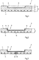
- Fig. 1 shows an exemplary embodiment of a precast concrete ceiling part 2 for a parking garage, which has a floor slab 4 made of concrete and with steel reinforcement 6.
- a recess 8 is provided for at least partially receiving an inductive charging station 10 (shown in dashed lines) in the base plate 4.
- the charging station 10 can thus be completely or at least partially sunk into the base plate 4 and thus "fused" in order to prevent it from protruding too far upwards.
- the fastening of the inductive charging station 10 in the recess 8 is preferably carried out by means of adhesive.
- a 2-component epoxy resin-based adhesive is used as the adhesive.
- mechanical fastening means can also be provided so that the charging station 10 can be latched or screwed on.
- the entire thickness d 1 must be reinforced so that the thickness d 2 below the recess 8 up to the vertical position of the reinforcement 6 is sufficiently large to provide sufficient reinforcement Way to protect against the ingress of water, especially water containing chloride.
- the thickness d 1 is increased by the depth d 3 of the recess 8 compared to a necessary thickness without a recess.
- the thickness dz is 55 mm, which is necessary to ensure sufficient stability of the base plate 4.
- FIG. 2 An embodiment according to the invention is shown in Fig. 2 shown.
- the recess 8 here has a protective layer 12 against the penetration of water into the base plate 4.
- the protective layer 12 prevents the penetration of water and thus represents additional protection, so that the thickness d 1 of the base plate 4 does not need to be reinforced, even if the distance between the bottom of the recess 8 and the reinforcement 6 is a predetermined distance d 2 (according to Fig. 1 ) of 55 mm, for example, does not comply.
- the protective layer 12 can be made of any material that meets the requirements for a protective effect.
- the material of the protective layer is preferably selected from one of the following materials: plastic with a good connection to the concrete, bitumen, asphalt, paint, epoxy resin, metal, in particular stainless steel or aluminum, ultra-high-strength concrete (UHPC - Ultra High Performance Concrete).
- UHPC - Ultra High Performance Concrete UHPC - Ultra High Performance Concrete.
- the illustrated embodiment has a protective layer 12 made of epoxy resin in the form of a multi-layer surface protection system OS 8 or OS 11 according to the RiLi SIB guideline.
- the preferred thickness of the protective layer 12 is between 1 and 4 mm, preferably between 1.5 and 2.5 mm.
- the protective layer 12 consists of an electrically conductive material
- a magnetic field shield is also implemented in addition to the protection against the ingress of water. This reduces the induction of magnetic fields within conductive reinforcement materials (steel, carbon) and losses and heating of the reinforcement and thus the concrete can be reduced or even avoided.
- the effectiveness of the shielding depends not only on the design of the protective layer 12, but also on the primary coil system arranged in the recess 8.
- the protective layer 12 can be poured in during the factory production of the base plate 4 or the protective layer 12 is subsequently connected to the base plate 4 and the recess 8.
- the recess 8 has an underside 14 and side walls 16 and thus forms a trough.
- the protective layer 12 is formed on the underside 14 and on the side walls 16.
- the base plate 4 can thus have a thickness of 10 to 15 cm, while the depth of the recess 8 is in the range of 2 to 5 cm. Depending on the application, the values mentioned can also be fallen below or exceeded.
- FIG. 13 shows a second embodiment with a structure similar to that in FIG Fig. 2 .
- the recess 8 has a protective layer made of ultra-high-strength concrete (UHPC).
- UHPC ultra-high-strength concrete
- the base plate 4 has a passage 18 to the underside of the base plate 4, through which a cable connection for one in the recess 8 arranged charging station 10 (not shown here) to enable.
- the passage 18 also has a protective layer 20 on the circumference.
- Fig. 4 shows the embodiment Fig. 3 with inserted charging station 10, which is connected by a cable 22 to an electrical supply below the base plate 4, the cable 22 being passed through the passage 18. Furthermore, the recess 8 has a cover 24 which, in the closed state, closes the recess 8 with the charging station 10 inserted at the top. Even if, as in Fig. 4 is shown, the cover 24 protrudes upwards in order to enable the charging station to be positioned as close as possible to a vehicle, the overall result is a good integration of the charging station in the base plate 4 with a minimization of the impairment of the use of the base plate 4 in a parking garage its user.
- the cover 24 is preferably made of a plastic or a metal and is intended to be able to withstand forces that are exerted on the cover 24 by a vehicle tire when it is driven away.
- Fig. 5 shows a third embodiment of a precast concrete floor part 2 according to the invention, in which the recess 8 is designed as an opening 24 with circumferential side walls 26 in the form of an opening and in which the protective layer 12 is formed on the side walls 26.
- the protective layer 12 itself has the shape of a trough with side walls 28 and a bottom 30.
- the entire thickness of the base plate 4 is used for the formation of the recess, the reinforcement 6 also being interrupted in the region of the recess 8. This interruption in the reinforcement can be compensated for by reinforcements during the manufacture of the base plate 4.
- the holding device in the form of the bottom 30 of the protective layer 12 for carrying and positioning a Charging station (not shown) provided.
- the holding device is thus made of the same material as the protective layer 12 and is formed integrally with the protective layer 12.
- Fig. 6 now shows a top view of a precast concrete ceiling part 2 according to the invention with a floor slab 4.
- the lower part 32 serves as one half of the roadway between two rows of parking spaces, while the upper part 34 realizes such a parking space.
- the recess 8 is in the transverse direction of the base plate 4 (horizontally in Fig. 6 ) arranged at a predetermined position in the center of the longitudinal edges 36.
- the two arrows x 1 and x 2 are therefore essentially of the same length.
- the recess 8 is arranged in the longitudinal direction of the base plate 4 at a predetermined position, which is characterized by the arrow y 1 relative to the front edge of the base plate 4. Inductive charging of a battery of the vehicle can thus be made possible regardless of the type of vehicle if the vehicle is parked in a suitable manner. There can be a parking aid that shows the driver how far he has to drive the vehicle in order to enable optimal charging.
- the recess 8 has an extent in the longitudinal direction which is greater, in particular at least twice as large as the longitudinal extent of the charging station 10.
- the recess 8 can have an extension in the transverse direction which is larger, in particular at least twice larger, than the transverse extension of the charging station. There is thus sufficient space within the recess 8 for a suitable arrangement of the charging station 10.
- this configuration is independent of the type and size of the charging station 10.
- Fig. 7 now shows an exemplary embodiment of a precast concrete component 2 with a textile reinforcement 40, which is arranged within the base plate 4 and preferably consists of carbon fibers.
- the base plate 4 does not need any additional protective measures when the recess 8 is made in the top of the base plate 4, i.e. neither an additional thickness, i.e. more concrete above the reinforcement, nor a protective layer as in the case of the previously described ones Embodiments.
- the structure of the base plate 4 is simplified even further.
- Fig. 8 shows an embodiment in which, as already for Fig. 3 has been described, the base plate 4 has a passage 18 to the underside of the base plate 4. The passage 18 is again used to lead through a cable connection.
Landscapes
- Engineering & Computer Science (AREA)
- Architecture (AREA)
- Civil Engineering (AREA)
- Structural Engineering (AREA)
- Mechanical Engineering (AREA)
- Physics & Mathematics (AREA)
- Electromagnetism (AREA)
- Road Paving Structures (AREA)
Description
- Die Erfindung betrifft ein Betonfertigdeckenteil für ein Parkhaus mit einer aus einem Beton hergestellten Bodenplatte und mit einer Ausnehmung, die für die zumindest teilweise Aufnahme einer induktiven Aufladestation in der Bodenplatte vorgesehen ist sowie ein Verfahren zum Herstellen eines Betonfertigdeckenteils für ein Parkhaus.
- Die Begriffe "Deckenteil" und "Bodenplatte" werden verwendet, da das Bauteil sowohl als Deckenteil als auch als Bodenteil dient. Die Oberseite ist die Stand- und Fahrfläche für die Fahrzeuge und die Unterseite ist die Decke für ein darunter angeordnetes Geschoss.
- Aus der
DE 20 2007 005 523 U1 ist ein solches Betonfertigdeckenteil bekannt, das zum Aufbau eines Parkhauses als Bodenplatte in ein Gerüst aus Stahlträgern eingebaut wird. Dabei weist eine solche Bodenplatte im Wesentlichen die Breite eines Stellplatzes für ein Fahrzeug und eine Länge gleich der Summe aus der Länge des Stellplatzes und der halben Breite der Fahrbahn zwischen zwei Reihen von Stellplätzen auf. Als Bewehrung wird in der genannten Schrift eine Stahlbetonbewehrung genannt. Aus derDE 10 2014 000 316 B4 ist eine derartige Bodenplatte mit einer Textilbewehrung bekannt. Eine solche Bewehrung kann auch aus Carbon bestehen. - Die Nutzung von Betonfertigdeckenteilen weist zahlreiche Vorteile gegenüber der Herstellung von Bodenplatten mit Ortbeton auf. Die industrielle werkseitige Herstellung der Betonfertigdeckenteile ermöglicht gleichbleibende und reproduzierbare Herstellungsbedingungen und damit eine hohe Zuverlässigkeit der eingesetzten Bauteile. Zudem ist der Aufbau des Parkhauses in kurzer Zeit und ohne große Zeitverzögerungen möglich.
- Die zuvor erwähnten Bodenplatten weisen herstellungsbedingt im Bereich der Oberseite eine höhere Betondichte und somit glatte und weitgehend wasserundurchlässige Oberfläche auf. Diese Eigenschaft wird dadurch erreicht, dass die Seite des Betonfertigteils, die während des Gießens und Aushärtens des Betons unten angeordnet ist, die spätere Oberseite bildet. Da beim Betongießen die unteren Bereiche des Betonvolumens stärker verdichten als die oberen Bereiche, kann das Betonfertigteil in umgedrehter Position in vorteilhafter Weise als Bodenplatte in einem Parkhaus eingesetzt werden. Die Dicke einer zuvor beschriebenen Bodenplatte liegt im Bereich von 10 cm bis 15 cm,wobei die angegebenen Werte auch unterschritten bzw. überschritten werden können.
- Bei herkömmlichen Stahlbetonbauteilen kann unter bestimmten Nutzungsbedingungen mit hoher Chlorideinwirkung, die von an den Fahrzeugen anhaftendem Spritzwasser mit Tausalzen herrührt, der Korrosionsschutz der Bewehrung im Laufe der Zeit ganz oder teilweise aufgehoben werden (Depassivierung). Dieser Tatsache wird durch eine ausreichend dicke Betondeckung Rechnung getragen, da die Eindringgeschwindigkeit der zu einer Depassivierung führenden Medien mit zunehmendem Alter stark abnimmt. Bei einem Beton mit ausreichender Stärke wird somit sichergestellt, dass der Betonstahl zumindest über die vorgesehene Nutzungsdauer seine Tragfähigkeit behält.
- Bei der herkömmlichen Betonstahlbewehrung übernimmt die Betondeckung weniger eine tragende, sondern in erster Linie eine schützende Funktion. Zur Sicherstellung des Verbundes genügt bereits eine Mindestbetondeckung in der Größenordnung von 4 bis 6 cm öder bis zu 10 cm Betondeckung.
- An die technische Ausstattung von Parkhäusern kommen durch den zunehmenden Gebrauch von Elektrofahrzeugen neue Anforderungen zu. Wegen begrenzter Reichweiten der Elektrofahrzeuge im Vergleich zu Fahrzeugen mit Verbrennungsmotoren ist es üblich und auch von den Fahrern gewünscht, dass die Parkdauer auch zum Aufladen der Batterien bzw. Akkumulatoren genutzt werden kann. Dazu sind einerseits kabelgebundene Aufladesysteme bekannt, bei denen der Benutzer eine Kabelverbindung mit der Aufladestation herstellen muss. Somit ist es erforderlich, dass vorgegebene Stellplätze mit einer kabelgebundenen Aufladestation ausgerüstet werden.
- Darüber hinaus ist auch das induktive Aufladen von Fahrzeugbatterien möglich, wobei ohne einen mechanischen Kontakt allein durch magnetische Induktion eine Fahrzeugbatterie aufgeladen.wird. Diese Technologie ist zudem für die Anwendungen interessant, bei denen durch selbstfahrende Fahrzeuge der Parkprozess automatisch abläuft. In diesem Fall muss das Aufladen ohne Zutun einer Person erfolgen, also durch induktive Aufladung.
- Aufladestationen für ein induktives Aufladen basieren auf der Kopplung zweier Spulen, wie es vom klassischen Transformator her bekannt ist. Da ein hoher Wirkungsgrad zu den wesentlichen Erfolgsfaktoren zählt, kommt es bei der Umsetzung zum einen auf einen geringen Abstand von der Primärspule auf dem Fahrbahn- bzw. Stellplatzboden zur Sekundärspule im Fahrzeug an. Zum anderen ist für minimale Streuverluste eine exakte Positionierung des Fahrzeugs notwendig. Aufgrund speziell ausgelegter Leistungselektronik und entsprechender Spulensysteme funktioniert das induktive Aufladen auch dann mit einem sehr guten Wirkungsgrad, wenn die Sekundärspule im Auto vertikal etwa 20 Zentimeter von der Spule im Boden entfernt ist. Selbst bei einem Luftspalt von 20 Zentimetern wird ein Wirkungsgrad von 93 bis 95 Prozent erreicht. Die Genauigkeit in horizontaler Richtung beschränkt sich beispielsweise auf einen Bereich von ca. 10 cm Versatz gegenüber einer optimalen Position, ohne dass es zu merklichen Verlusten kommt.
- Bisherige Aufladesysteme, die hauptsächlich für den privaten Gebrauch bestimmt sind, bestehen aus einer Primärspulenenanordnung, die auf die Bodenoberfläche aufgelegt wird, wobei elektrische Kabel oberflächennah zugeführt werden. Ein solches Anbringen von Aufladesystemen ist jedoch für öffentlich zugängliche Stellplätze wegen zahlreicher Nachteile wenig geeignet. So stellt eine auf der Bodenplatte aufgelegte Aufladestation eine Stolperfalle und zusätzlich ein Hindernis beim Einparken dar. Zudem wird die Reinigung der Bodenplatten erschwert und auch die Diebstahlgefahr ist wegen der öffentlichen Zugänglichkeit ein Problem. Schließlich ist eine offene elektrische Kabelführung unsicher.
- Aus der
EP 2 876 232 A1 ist ein modularer Unterstellplatz für Fahrzeuge bekannt, welcher eine Bodenplatte, zwei Seitenwände und ein Dach umfasst. Auf dem Dach ist eine Anzahl von Solarmodulen angeordnet, die mit in der Bodenplatte angeordneten Induktionsspulen gekoppelt sind. - Die
EP 0 788 212 A2 offenbart einen Parkplatz für ein Elektrofahrzeug, welcher eine Ausnehmung für eine Spulenbewegungsvorrichtung aufweist, wobei die Spulenbewegungsvorrichtung dazu ausgestaltet ist, eine Primärspule in der Ausnehmung bewegbar abzustützen bzw. zu tragen. - Daher liegt der vorliegenden Erfindung das technische Problem zugrunde, die Ausstattung von Parkhäusern mit induktiven Aufladesystemen zu verbessern.
- Das zuvor aufgeführte technische Problem wird erfindungsgemäß dadurch gelöst, dass die Bodenplatte mit einer Bewehrung versehen ist, dass die Ausnehmung in der Oberseite der Bodenplatte ausgebildet ist und dass die Ausnehmung eine Schutzschicht gegen das Eindringen von Wasser in die Bodenplatte aufweist.
- Erfindungsgemäß ist daher erkannt worden, dass die Bodenplatte für ein Parkhaus eine geeignet ausgestaltete Ausnehmung bzw. Vertiefung aufweist, in der die Aufladestation zumindest zu einem Teil in vertikaler Richtung aufgenommen wird. In dieser Ausnehmung kann die Aufladestation fixiert und gegebenenfalls diebstahlsicher befestigt werden. Zudem kann die elektrische Zuleitung in der Bodenplatte zumindest teilweise und somit stolpersicher integriert werden. Die Aufladestation wird also mehr oder weniger mit der Bodenplatte "verschmolzen".
- Die Bewehrung der Bodenplatte kann aus verschiedenen Materialien bestehen. Beispielsweise besteht die Bewehrung aus Stahl, insbesondere Baustahl und/oder aus einem Textil, vorzugsweise bestehend aus Fasern aus Kunststoff, Carbon/Kohlefasern oder einem anderen Textilmaterial. Vorzugsweise ist die Textilbewehrung eine nichtmetallische Bewehrung, insbesondere bestehend aus Glasfasern, Carbonfasern, Aramidfasern oder Basaltfasern oder eine Mischung hiervon. Außerdem kann die Textilbewehrung aus textilen bzw. anorganischen Fasern oder Faserbündeln bestehen. Anstelle einer Gewebestruktur kann die Bewehrung aus einzelnen, insbesondere unregelmäßig verteilten Fasern, insbesondere Carbonfasern bestehen.
- Besteht die Bewehrung der Bodenplatte aus einer nicht-rostanfälligen Bewehrung, beispielsweise aus einer Textilbewehrung, insbesondere aus Carbon, so kann die Ausnehmung in das Material der Bodenplatte eingearbeitet werden und eine nachfolgend beschriebene Verstärkung der Betonabdeckung der Bewehrung ist nicht erforderlich. Somit ergibt sich eine erfindungsgemäße einfache Bodenplatte, insbesondere aus Carbonbeton, in der eine Ausnehmung eingebracht ist.
- Das zuvor beschriebene alleinige Einbringen der Ausnehmung in die Bodenplatte erfordert aus den oben geschilderten Gründen bei einer Stahlbewehrung jedoch eine Verstärkung der gesamten Bodenplatte, da auch im Bereich der Ausnehmung ein ausreichender Schutz vor Korrosion gewährleistet werden muss. Gleichwohl wird der Nachteil einer größeren Dicke der Bodenplatte durch die Vorteile bei der Anbringung der induktiven Aufladestation mehr als aufgehoben.
- Das Problem der geringeren Stärke der Bodenplatte im Bereich der Ausnehmung wird dadurch behoben, dass die Ausnehmung eine Schutzschicht gegen das Eindringen von Wasser in die Bodenplatte aufweist. Durch diese Zusatzmaßnahme kann die ursprüngliche Dicke der Bodenplatte beibehalten werden, wodurch der Einsatz von mehr Beton vermieden wird.
- Vorzugsweise ist die Schutzschicht aus einem der Materialien ausgewählt: Kunststoff mit guter Anbindung an den Beton, Bitumen, Asphalt, Lack, Epoxydharz, Metall, insbesondere Edelstahl oder Aluminium. In jedem Fall bietet das Material der Schutzschicht einen ausreichenden Schutz vor dem Eindringen von chloridhaltigem Wasser in den Beton im Bereich und vor allem unter der Ausnehmung.
- Sofern erforderlich kann die Schutzschicht mit geeigneten Klebern mit dem Beton der Bodenplatte verbunden werden. Insbesondere gilt dieses für eine Kunststoffbeschichtung aus einem vorgefertigten Kunststoffteil, das in der Ausnehmung, insbesondere vollflächig, verklebt wird.
- Eine Schutzschicht aus Bitumen, Asphalt oder Lack wird als fließfähige Schicht aufgebracht und verbindet sich vorzugsweise vollflächig mit der Oberfläche der Ausnehmung. Bevorzugt wird ein Epoxydharzsystem eingesetzt, das insbesondere mehrschichtig aufgebracht wird. So ist eine Ausgestaltung der Epoxydharzbeschichtung als ein- oder mehrschichtiges Oberflächenschutzsystem OS 8 oder OS 11 nach der Richtlinie RiLi SIB ("Schutz und Instandsetzung von Betonbauteilen") des Deutschen Ausschusses für Stahlbeton (DAfStb) möglich.
- Die Schutzschicht kann auch aus einem Ultrahochleistungsbeton (englisch Ultra High Performance Concrete, gebräuchliche Abkürzung UHPC) oder aus einem Ultrahochfester Beton (UHFB) bestehen. Diese Betonsorte zeichnet sich durch besonders hohe Dichtigkeit und Festigkeit gegenüber einem normalen Beton aus.
- In einer ersten vorteilhaften Ausgestaltung weist die Ausnehmung eine Unterseite und Seitenwände auf und bildet somit eine Wanne. Die Schutzschicht ist dann an der Unterseite und an den Seitenwänden ausgebildet und bildet den Schutz vor Eindringen von Wasser an allen Seiten der Ausnehmung, die mit Beton umgeben sind.
- Die Ausnehmung ist in der Oberseite der Bodenplatte ausgebildet, um einen möglichst geringen Abstand von der Sekundärspule im Fahrzeug zu erreichen.
- Bei einer Ausnehmung an der Unterseite der Bodenplatte, muss die besonders dichte Oberseite der Bodenplatte nicht durch die Ausnehmung beschädigt werden. Gleichwohl muss der Nachteil eines größeren Abstandes der in der Ausnehmung angeordneten Primärspule zur Sekundärspule im Fahrzeug in Kauf genommen werden. Die Verkabelung der Aufladestation verläuft dagegen in diesem Fall in vorteilhafter Weise vollständig an der Unterseite der Bodenplatte und stellt keine Stolpergefahr mehr dar.
- Dieser Vorteil kann bei einer in der Oberseite der Bodenplatte ausgebildeten Ausnehmung dadurch erreicht werden, dass die Ausnehmung einen Durchgang zur Unterseite der Bodenplatte aufweist. Durch diesen Durchgang kann die elektrische Versorgung der Aufladestation in der Ausnehmung von unten erfolgen, ohne dass eine Verkabelung auf der Oberseite der Bodenplatte verlaufen muss.
- Mit zumindest einem Teil der zuvor beschriebenen Maßnahmen ist eine Ausgestaltung der Bodenplatte mit einer Dicke von 10 bis 15 cm weiterhin möglich, wobei bevorzugt die Tiefe der Ausnehmung im Bereich von 2 bis 5 cm oder von mehr als 5 cm liegt. Die angegebenen Werte können auch unterschritten bzw. unterschritten werden.
- In einer weiteren vorteilhaften Ausgestaltung ist die Ausnehmung als Öffnung der Bodenplatte mit umlaufenden Seitenwänden als Durchbruch ausgebildet, wobei die Schutzschicht an den Seitenwänden ausgebildet ist. In diesem Fall wird die Bodenplatte durch die seitliche Schutzschicht vor dem Eindringen von Wasser geschützt.
- Da die Öffnung nach unten nicht abgeschlossen ist, ist es vorteilhaft, dass in der Ausnehmung eine sich horizontal erstreckende Haltevorrichtung zum Tragen und Positionieren der Aufladestation vorgesehen ist. Dabei ist es weiterhin bevorzugt, dass die Haltevorrichtung aus dem gleichen Material wie die Schutzschicht, insbesondere integral mit der Schutzschicht ausgebildet ist. Somit kann in bevorzugter Weise eine Wanne aus dem Material der Schutzschicht ausgebildet und in der Öffnung der Ausnehmung angeordnet sein. Insbesondere kann eine Wanne aus ultrahochfestem Beton (UHPC) gebildet und in die Ausnehmung eingesetzt sein.
- Für alle zuvor beschriebenen Ausgestaltungen ist es vorteilhaft, wenn die Ausnehmung einen Deckel aufweist. Dadurch kann die Aufladestation innerhalb des von der Ausnehmung und dem Deckel aufgespannten Volumens angeordnet sein und der Deckel verschließt dieses Volumen und verhindert weitgehend das Eindringen von Wasser und Verunreinigungen in die Ausnehmung.
- Wie oben beschrieben worden ist, kommt es auf eine ausreichend gute Positionierung der Aufladestation relativ zum Fahrzeug an. Daher ist es bevorzugt, dass die Ausnehmung in Querrichtung der Bodenplatte an einer vorgegebenen Position, insbesondere mittig zu den Längskanten angeordnet ist. Somit kann ein elektrisch betriebenes Fahrzeug mittig auf dem Stellplatz abgestellt werden, um ein optimales Aufladen der Batterie des Fahrzeugs zu ermöglichen.
- Die Positionierung der Aufladestation in Fahrtrichtung ist ebenfalls zu berücksichtigen, so dass in weiter bevorzugter Weise die Ausnehmung in Längsrichtung der Bodenplatte an einer vorgegebenen Position angeordnet ist, um unabhängig vom Fahrzeugtyp ein induktives Aufladen eines Akkumulators des Fahrzeugs zu ermöglichen.
- Des Weiteren ist es bevorzugt, dass die Ausnehmung eine Erstreckung in Längsrichtung aufweist, die größer, insbesondere mindestens zweifach größer als die Längsausdehnung der Aufladestation ist. Ebenso oder alternativ dazu kann die Ausnehmung eine Erstreckung in Querrichtung aufweisen, die größer, insbesondere mindestens zweifach größer als die Querausdehnung der Aufladestation ist. Durch eine der beiden oder beide Maßnahmen ist eine variable Positionierung und Fixierung der Aufladestation innerhalb der Ausnehmung möglich. Zudem ist die Ausbildung der Ausnehmung weitgehend unabhängig von der Wahl der Aufladestation, die in unterschiedlichen Größen hergestellt werden.
- Das Abstellen von Fahrzeugen auf den Stellplätzen erfolgt nicht immer gleich und in wiederholbarer Genauigkeit. Daher wird als unabhängige Lösung des oben beschriebenen technischen Problems, also unabhängig von der Ausbildung einer Ausnehmung in der Bodenplatte, vorgeschlagen, eine Bewegungsvorrichtung zum Positionieren der Aufladestation auf der Bodenplatte vorzusehen. Bezogen auf die oben beschriebene Lösung ist die Bewegungsvorrichtung dann innerhalb der Ausnehmung angeordnet.
- Die Bewegungsvorrichtung weist eine relativ zur Bodenplatte bewegbare Mimik auf, auf der die Aufladestation befestigt werden kann. Durch einen motorischen Antrieb kann dann die Bewegungsvorrichtung in eine Position verfahren werden, in der eine bezogen auf die aktuelle Abstellposition des Fahrzeugs bestmögliche Aufladung der Batterie im Fahrzeug ermöglicht wird. Dabei kann die Bewegungsvorrichtung in vorteilhafter Weise eine Bewegungskomponente in Längsrichtung und/oder in Querrichtung des Stellplatzes aufweisen. Der Bewegungsfreiraum der Ausnehmung kann somit auch nach der Installation der Aufladestation variabel ausgenutzt werden.
- Die Bewegungsvorrichtung kann auch ähnlich wie bei einem Rasenmäherroboter ausgebildet sein und eine Bewegung unabhängig von Schienen ermöglichen. Somit kann die Aufladestation ohne Ausnehmung in der Bodenplatte frei auf der Oberfläche der Bodenplatte bewegt werden. Bei einer Anordnung in der Ausnehmung der Bodenplatte kann die Aufladestation frei innerhalb des von der Ausnehmung und der darin angeordneten Schutzschicht aufgespannten Fläche bewegt werden.
- Des Weiteren ist es vorteilhaft, wenn die Ausnehmung eine Anhebevorrichtung zum vertikalen Anheben der Aufladestation aufweist. Damit kann bei einem Abstellen des Fahrzeugs auf der Bodenplatte oberhalb der Ausnehmung der vertikale Versatz der Aufladestation in der Ausnehmung zumindest teilweise aufgehoben werden.
- Wie eingangs erwähnt worden ist, besteht die Bewehrung der Bodenplatte aus Stahl, insbesondere Baustahl und/oder aus einem Textil, vorzugsweise bestehend aus Fasern aus Kunststoff, Carbon/Kohlefasern oder einem anderen Textilmaterial. Vorzugsweise ist die Textilbewehrung eine nichtmetallische Bewehrung, insbesondere bestehend aus Glasfasern, Carbonfasern, Aramidfasern oder Basaltfasern oder eine Mischung hiervon. Außerdem kann die Textilbewehrung aus textilen bzw. anorganischen Fasern oder Faserbündeln bestehen.
- Die für das induktive Aufladen von Batterien erzeugten magnetischen Wechselfelder führen in elektrisch leitfähigen Materialien, also insbesondere in einer Stahlbewehrung, zu induzierten elektrischen Strömen. Diese induzierten Ströme führen einerseits zu einem Wirkverlust und zum anderen zu einer teilweise starken Erwärmung der Stahlbewehrung. Diese Erwärmung ist auf den Bereich der Ausnehmung beschränkt, da die Aufladestationen so dimensioniert und gestaltet werden, dass das entstehende Magnetfeld möglichst gut und weitgehend in Richtung der Sekundärspule verläuft. Gleichwohl wird durch eine dauerhafte und wiederkehrende lokale Erwärmung der Stahlbewehrung eine zusätzliche Belastung in die Bodenplatte eingeleitet.
- Daher wird als unabhängige Lösung des oben beschriebenen technischen Problems, also unabhängig von der Ausbildung einer Ausnehmung in der Bodenplatte, vorgeschlagen, dass die Bewehrung im Bereich der Ausnehmung aus einem Textil bestehend aus einem nicht elektrisch leitfähigen Material und außerhalb des Bereichs der Ausnehmung aus Stahl besteht. Somit wird eine hybride Ausgestaltung der Bewehrung der Bodenplatte vorgeschlagen, teilweise bestehend aus herkömmlichem Stahl und teilweise bestehend aus Textil. Wenn die Aufladestation im Bereich der Textilbewehrung angeordnet ist, dann erfolgt keine oder nur eine geringe Erwärmung und Belastung der Bodenplatte. Der vorgenannte Bereich kann dadurch bestimmt werden, dass in einem vorgegebenen Abstand um eine vorgegebene Position der Bodenplatte herum die Textilbewehrung angeordnet ist, die außerhalb dann in eine Stahlbewehrung übergeht.
- Bei der Ausgestaltung mit Ausnehmung in der Bodenplatte ist die Ausnehmung im Bereich der Textilbewehrung angeordnet, um ebenfalls die Aufladestation im Bereich der Textilbewehrung anzuordnen.
- Das zuvor beschriebene Betonfertigdeckenteil wird werkseitig hergestellt und baustellenseitig in einem Parkhaus installiert. Regelmäßig erfolgt die Installation der induktiven Aufladestation anschließend vor Ort. Ebenso ist es aber auch möglich bereits werkseitig die Aufladestation zu installieren. In diesem Fall ist ein Betonfertigdeckenteil dadurch weitergebildet, dass eine induktive Aufladestation in der Ausnehmung angeordnet, insbesondere befestigt, vorzugsweise mittels Klebstoff oder durch eine mechanische Befestigungsvorrichtung verbunden ist. Als Klebstoff kommt dabei bevorzugt ein 2-komponentiger Kleber auf Epoxydharzbasis zur Anwendung.
- Das oben aufgezeigt technische Problem wird erfindungsgemäß auch durch Verfahren zum Herstellen eines Betonfertigdeckenteils für ein Parkhaus nach einem der Ansprüche 1 bis 9 gelöst, bei dem in einer Schalung eine Bewehrung angeordnet wird, bei dem in der Schalung ein Ausschalungselement für das Ausbilden einer Ausnehmung angeordnet wird, bei dem zur Herstellung einer Bodenplatte die Schalung mit einem Beton ausgefüllt wird und bei dem die Ausnehmung mit einer Schutzschicht versehen wird.
- In bevorzugter Weise wird nach dem Aushärten des Betons das Ausschalungselement entnommen, so dass die Ausnehmung in der fertigen Bodenplatte ausgebildet ist und danach mit einer Schutzschicht versehen wird, wie es oben beschrieben worden ist.
- Alternativ dazu kann nach dem Aushärten des Betons das Ausschalungselement in der Bodenplatte verbleiben und direkt als Schutzschicht verwendet werden. Insbesondere kann dabei das Ausschalungselement aus einem ultrahochfesten Beton (UHPC) bestehen, das sich gut mit dem eingefüllten Beton verbindet.
- Im Folgenden wird die Erfindung anhand von Ausführungsbeispielen mit Bezug auf die Zeichnung erläutert. In der Zeichnung zeigen
- Fig. 1
- ein Ausführungsbeispiel eines nicht erfindungsgemäßen Betonfertigdeckenteils,
- Fig. 2
- ein erstes Ausführungsbeispiel eines erfindungsgemäßen Betonfertigdeckenteils,
- Fig. 3
- ein zweites Ausführungsbeispiel eines erfindungsgemäßen Betonfertigdeckenteils,
- Fig. 4
- das zweite Ausführungsbeispiel mit eingesetzter Aufladestation,
- Fig. 5
- ein drittes Ausführungsbeispiel eines erfindungsgemäßen Betonfertigdeckenteils,
- Fig. 6
- ein Betonfertigdeckenteil in einer Draufsicht,
- Fig. 7
- ein weiteres Ausführungsbeispiel eines nicht erfindungsgemäßen Betonfertigdeckenteils und
- Fig. 8
- ein weiteres Ausführungsbeispiel eines nicht erfindungsgemäßen Betonfertigdeckenteils.
- In der nachfolgenden Beschreibung von verschiedenen Ausführungsbeispielen werden Bauteile und Elemente mit gleicher Funktion und gleicher Wirkungsweise mit denselben Bezugszeichen versehen, auch wenn die Bauteile und Elemente bei den verschiedenen Ausführungsbeispielen in ihrer Dimension oder Form Unterschiede aufweisen können.
-
Fig. 1 zeigt ein Ausführungsbeispiel eines Betonfertigdeckenteils 2 für ein Parkhaus, das eine aus einem Beton hergestellte Bodenplatte 4 mit einer Stahlbewehrung 6 aufweist. Eine Ausnehmung 8 ist für die zumindest teilweise Aufnahme einer induktiven Aufladestation 10 (gestrichelt dargestellt) in der Bodenplatte 4 vorgesehen. Somit kann die Aufladestation 10 ganz oder zumindest teilweise in der Bodenplatte 4 versenkt und somit "verschmolzen" werden, um ein zu weites Vorstehen nach oben zu verhindern. - Die Befestigung der induktiven Aufladestation 10 in der Ausnehmung 8 erfolgt in bevorzugter Weise mittels Klebstoff. Als Klebstoff kommt dabei ein 2-komponentiger Kleber auf Epoxydharzbasis zur Anwendung. Alternativ können auch mechanische Befestigungsmittel vorgesehen sein, so dass die Aufladestation 10 eingerastet oder angeschraubt werden kann.
- Da die Ausnehmung 4 einen Teil der vertikalen Erstreckung der Bodenplatte 4 entfernt, muss die gesamte Dicke d1 so weit verstärkt werden, dass die Dicke d2 unterhalb der Ausnehmung 8 bis zur vertikalen Position der Bewehrung 6 genügend groß ist, um die Bewehrung in ausreichender Weise vor dem Eindringen von Wasser, insbesondere von chloridhaltigen Wasser zu schützen. Mit anderen Worten, die Dicke d1 ist um die Tiefe d3 der Ausnehmung 8 gegenüber einer notwendigen Dicke ohne Ausnehmung vergrößert.
- Beispielsweise beträgt die Dicke dz 55 mm, die für eine Gewährleistung einer ausreichenden Standfestigkeit der Bodenplatte 4 notwendig ist.
- Eine erfindungsgemäße Ausgestaltung ist in
Fig. 2 gezeigt. Die Ausnehmung 8 weist hier eine Schutzschicht 12 gegen das Eindringen von Wasser in die Bodenplatte 4 auf. Die Schutzschicht 12 verhindert das Eindringen von Wasser und stellt somit einen zusätzlichen Schutz dar, so dass die Dicke d1 der Bodenplatte 4 nicht verstärkt zu werden braucht, auch wenn der Abstand zwischen dem Boden der Ausnehmung 8 und der Bewehrung 6 einen vorgegebenen Abstand d2 (gemäßFig. 1 ) von beispielsweise 55 mm nicht einhält. - Die Schutzschicht 12 kann aus einem beliebigen Material hergestellt sein, das die Anforderungen an eine Schutzwirkung erfüllt. Bevorzugt ist das Material der Schutzschicht aus einem der folgenden Materialien ausgewählt: Kunststoff mit guter Anbindung an den Beton, Bitumen, Asphalt, Lack, Epoxydharz, Metall, insbesondere Edelstahl oder Aluminium, ultrahochfester Beton (UHPC - Ultra High Performance Concrete). Das in
Fig. 2 dargestellte Ausführungsbeispiel weist eine Schutzschicht 12 aus Epoxydharz in Form eines mehrschichtigen Oberflächenschutzsystems OS 8 oder OS 11 nach der Richtlinie RiLi SIB auf. In diesem Fall beträgt die bevorzugte Dicke der Schutzschicht 12 zwischen 1 und 4 mm, vorzugsweise zwischen 1,5 und 2,5 mm. - Sofern die Schutzschicht 12 aus einem elektrisch leitfähigem Material besteht, wird neben dem Schutz vor Eindringen von Wasser auch noch eine Magnetfeld-Abschirmung verwirklicht. Dadurch wird eine Induktion von Magnetfeldern innerhalb von leitfähigen Bewehrungsmaterialien (Stahl, Carbon) vermindert und Verluste und ein Erwärmen der Bewehrung und damit des Betons können verringert oder sogar vermieden werden. Die Effektivität der Abschirmung hängt dabei nicht nur von der Ausgestaltung der Schutzschicht 12 ab, sondern auch von dem in der Ausnehmung 8 angeordneten Primärspulensystem.
- Die Schutzschicht 12 kann während der werkseitigen Herstellung der Bodenplatte 4 eingegossen werden oder die Schutzschicht 12 wird nachträglich mit der Bodenplatte 4 und der Ausnehmung 8 verbunden.
- Wie
Fig. 2 weiterhin zeigt, weist die Ausnehmung 8 eine Unterseite 14 und Seitenwände 16 auf und bildet somit eine Wanne. Ein ausreichender Schutz wird im dargestellten Ausführungsbeispiel gewährleistet, indem die Schutzschicht 12 an der Unterseite 14 und an den Seitenwänden 16 ausgebildet ist. - Somit kann die Bodenplatte 4 eine Dicke von 10 bis 15 cm aufweisen, während die Tiefe der Ausnehmung 8 im Bereich von 2 bis 5 cm liegt. Die genannten Werte können je nach Anwendung auch unter- bzw. überschritten werden.
-
Fig. 3 zeigt ein zweites Ausführungsbeispiel mit einem ähnlichen Aufbau wie inFig. 2 . Vorliegend weist die Ausnehmung 8 eine Schutzschicht aus ultrahochfesten Beton (UHPC) auf. Zusätzlich weist die Bodenplatte 4 einen Durchgang 18 zur Unterseite der Bodenplatte 4 auf, durch den eine Kabelverbindung für eine in der Ausnehmung 8 angeordnete Aufladestation 10 (hier nicht dargestellt) zu ermöglichen. Der Durchgang 18 weist umfangseitig ebenfalls eine Schutzschicht 20 auf. -
Fig. 4 zeigt das Ausführungsbeispiel nachFig. 3 mit eingesetzter Aufladestation 10, die mit einem Kabel 22 mit einer elektrischen Versorgung unterhalb der Bodenplatte 4 verbunden ist, wobei das Kabel 22 durch den Durchgang 18 hindurch geführt ist. Des Weiteren weist die Ausnehmung 8 einen Deckel 24 auf, der im geschlossenen Zustand die Ausnehmung 8 mit eingesetzter Aufladestation 10 nach oben hin abschließt. Selbst wenn, wie inFig. 4 dargestellt ist, der Deckel 24 nach oben vorsteht, um eine Positionierung der Aufladestation möglichst nahe an einem Fahrzeug zu ermöglichen, so ergibt sich insgesamt eine gute Einbindung der Aufladestation in der Bodenplatte 4 mit einer Minimierung der Beeinträchtigung der Nutzung der Bodenplatte 4 in einem Parkhaus durch dessen Benutzer. - Der Deckel 24 besteht bevorzugt aus einem Kunststoff oder aus einem Metall und soll Kräfte aushalten können, die von einem Fahrzeugreifen durch ein Hinwegfahren auf den Deckel 24 ausgeübt werden.
-
Fig. 5 zeigt ein drittes Ausführungsbeispiel eines erfindungsgemäßen Betonfertigbodenteils 2, bei dem die Ausnehmung 8 als Öffnung 24 mit umlaufenden Seitenwänden 26 in Form eines Durchbruchs ausgebildet ist und bei dem die Schutzschicht 12 an den Seitenwänden 26 ausgebildet ist. Die Schutzschicht 12 hat dabei selbst die Form einer Wanne mit Seitenwänden 28 und einem Boden 30. - Somit wird bei diesem Ausführungsbeispiel die gesamte Stärke der Bodenplatte 4 für die Ausbildung der Ausnehmung genutzt, wobei auch die Bewehrung 6 im Bereich der Ausnehmung 8 unterbrochen ist. Diese Unterbrechung der Bewehrung kann bei der Herstellung der Bodenplatte 4 durch Verstärkungen ausgeglichen werden.
- In der Ausnehmung 8 ist somit eine sich horizontal erstreckende Haltevorrichtung in Form des Bodens 30 der Schutzschicht 12 zum Tragen und Positionieren einer Aufladestation (nicht dargestellt) vorgesehen. Somit ist die Haltevorrichtung aus dem gleichen Material wie die Schutzschicht 12 und integral mit der Schutzschicht 12 ausgebildet.
-
Fig. 6 zeigt nun eine Draufsicht auf ein erfindungsgemäßes Betonfertigdeckenteil 2 mit einer Bodenplatte 4. Der untere Teil 32 dient im fertigen Parkhaus als eine Hälfte der Fahrbahn zwischen zwei Reihen von Stellplätzen, während der obere Teil 34 einen solchen Stellplatz verwirklicht. - Die Ausnehmung 8 ist in Querrichtung der Bodenplatte 4 (horizontal in
Fig. 6 ) an einer vorgegebenen Position mittig zu den Längskanten 36 angeordnet. Die beiden Pfeile x1 und x2 sind daher im Wesentlichen gleich lang. Wenn dann ein Fahrzeug mittig auf der Bodenplatte 4 abgestellt wird, kann ein Aufladen mit einer in der Ausnehmung 8 angeordneten Aufladestation die Batterie des Fahrzeugs aufgeladen werden. - Des Weiteren ist die Ausnehmung 8 in Längsrichtung der Bodenplatte 4 an einer vorgegebenen Position angeordnet, die mit dem Pfeil y1 relativ zum vorderen Rand der Bodenplatte 4 charakterisiert ist. Somit kann unabhängig vom Fahrzeugtyp ein induktives Aufladen eines Akkumulators des Fahrzeugs ermöglicht werden, wenn das Fahrzeug in geeigneter Weise abgestellt wird. Hierbei kann es eine Einparkhilfe geben, die dem Fahrer anzeigt, wie weit er das Fahrzeug vorfahren muss, um ein optimales Aufladen zu ermöglichen.
- Um ein variables Anordnen der Aufladestation innerhalb der Ausnehmung 8 zu ermöglichen, weist die Ausnehmung 8 eine Erstreckung in Längsrichtung auf, die größer, insbesondere mindestens zweifach größer als die Längsausdehnung der Aufladestation 10 ist. Ebenso kann die Ausnehmung 8 eine Erstreckung in Querrichtung aufweisen, die größer, insbesondere mindestens zweifach größer als die Querausdehnung der Aufladestation ist. Somit ist genügend Platz innerhalb der Ausnehmung 8 für ein geeignetes Anordnen der Aufladestation 10. Zudem ist diese Ausgestaltung unabhängig vom Typ und Größe der Aufladestation 10.
-
Fig. 7 zeigt nun ein Ausführungsbeispiel eines Betonfertigbauteils 2 mit einer innerhalb der Bodenplatte 4 angeordneten Textilbewehrung 40, die bevorzugt aus Carbonfasern besteht. Durch das Verwenden einer nicht-rostenden Bewehrung benötigt die Bodenplatte 4 keine zusätzlichen Schutzmaßnahmen, wenn die Vertiefung 8 in die Oberseite der Bodenplatte 4 eingebracht wird, also weder eine zusätzliche Dicke, also mehr Beton oberhalb der Bewehrung, noch eine Schutzschicht wie bei den zuvor beschriebenen Ausführungsbeispielen. Der Aufbau der Bodenplatte 4 wird dadurch nochmals vereinfacht. -
Fig. 8 zeigt ein Ausführungsbeispiel, bei dem, wie schon zurFig. 3 beschrieben worden ist, die Bodenplatte 4 einen Durchgang 18 zur Unterseite der Bodenplatte 4 aufweist. Der Durchgang 18 dient erneut einer Durchführung einer Kabelverbindung.
Claims (12)
- Betonfertigdeckenteil für ein Parkhaus,- mit einer aus einem Beton hergestellten Bodenplatte (4) und- mit einer Ausnehmung (8), die für die zumindest teilweise Aufnahme einer induktiven Aufladestation (10) in der Bodenplatte (4) vorgesehen ist,
dadurch gekennzeichnet,- dass die Bodenplatte (4) mit einer Bewehrung (6; 40) versehen ist,- dass die Ausnehmung in der Oberseite der Bodenplatte (4) ausgebildet ist und- dass die Ausnehmung (8) eine Schutzschicht (12) gegen das Eindringen von Wasser in die Bodenplatte (4) aufweist - Betonfertigdeckenteil nach Anspruch 1,
dadurch gekennzeichnet,
dass die Schutzschicht (12) aus einem der Materialien ausgewählt ist:
Kunststoff, Bitumen, Asphalt, Lack, Epoxydharz, Metall, insbesondere Edelstahl oder Aluminium, ultrahochfester Beton (UHPC - Ultra High Performance Concrete). - Betonfertigdeckenteil nach Anspruch 1 oder 2,
dadurch gekennzeichnet,- dass die Ausnehmung (8) eine Unterseite (14) und Seitenwände (16) aufweist und- dass die Schutzschicht (12) an der Unterseite (14) und an den Seitenwänden (16) ausgebildet ist. - Betonfertigdeckenteil nach einem der Ansprüche 1 bis 3,
dadurch gekennzeichnet,
dass die Ausnehmung (8) einen Durchgang (18) zur Unterseite der Bodenplatte (4) aufweist. - Betonfertigdeckenteil nach einem der Ansprüche 1 bis 4,
dadurch gekennzeichnet,
dass die Ausnehmung (8) einen Deckel (24) aufweist. - Betonfertigdeckenteil nach Anspruch 1 oder 2,
dadurch gekennzeichnet,- dass die Ausnehmung (8) als Öffnung (25) mit umlaufenden Seitenwänden (26) ausgebildet ist und- dass die Schutzschicht (12) an den Seitenwänden (26) ausgebildet ist. - Betonfertigdeckenteil nach Anspruch 6,
dadurch gekennzeichnet,
dass in der Ausnehmung (8) eine sich horizontal erstreckende Haltevorrichtung (30) zum Tragen und Positionieren der Aufladestation (10) vorgesehen ist. - Betonfertigdeckenteil nach Anspruch 7,
dadurch gekennzeichnet,
dass die Haltevorrichtung (30) aus dem gleichen Material wie die Schutzschicht (12), insbesondere integral mit der Schutzschicht (12) ausgebildet ist. - Betonfertigdeckenteil nach einem der Ansprüche 1 bis 8,
dadurch gekennzeichnet,
dass eine induktive Aufladestation (10) in der Ausnehmung (8) angeordnet, insbesondere befestigt, vorzugsweise mittels Klebstoff oder durch eine mechanische Befestigungsvorrichtung verbunden ist. - Verfahren zum Herstellen eines Betonfertigdeckehteils für ein Parkhaus nach einem der Ansprüche 1 bis 9,- bei dem in einer Schalung eine Bewehrung angeordnet wird,- bei dem in der Schalung ein Ausschalungselement für das Ausbilden einer Ausnehmung angeordnet wird,- bei dem zur Herstellung einer Bodenplatte die Schalung mit einem Beton ausgefüllt wird und- bei dem die Ausnehmung mit einer Schutzschicht versehen wird.
- Verfahren nach Anspruch 10,
bei dem nach dem Aushärten des Betons das Ausschalungselement entnommen wird. - Verfahren nach Anspruch 10,
bei dem nach dem Aushärten des Betons das Ausschalungselement in der Bodenplatte verbleibt und als Schutzschicht verwendet wird.
Applications Claiming Priority (1)
| Application Number | Priority Date | Filing Date | Title |
|---|---|---|---|
| DE102017117623.3A DE102017117623A1 (de) | 2017-08-03 | 2017-08-03 | Betonfertigdeckenteil für ein Parkhaus und Verfahren zur Herstellung |
Publications (2)
| Publication Number | Publication Date |
|---|---|
| EP3438366A1 EP3438366A1 (de) | 2019-02-06 |
| EP3438366B1 true EP3438366B1 (de) | 2021-07-21 |
Family
ID=63144815
Family Applications (1)
| Application Number | Title | Priority Date | Filing Date |
|---|---|---|---|
| EP18186289.7A Active EP3438366B1 (de) | 2017-08-03 | 2018-07-30 | Betonfertigdeckenteil für ein parkhaus und verfahren zur herstellung |
Country Status (2)
| Country | Link |
|---|---|
| EP (1) | EP3438366B1 (de) |
| DE (1) | DE102017117623A1 (de) |
Families Citing this family (6)
| Publication number | Priority date | Publication date | Assignee | Title |
|---|---|---|---|---|
| DE102017117278B4 (de) | 2017-07-31 | 2022-04-28 | Witzenmann Gmbh | Anschlussvorrichtung und Verfahren zum Temperieren und elektrischen Kontaktieren eines Elektromoduls |
| CN111549983A (zh) * | 2020-05-15 | 2020-08-18 | 中能化江苏地质矿产设计研究院有限公司 | 一种新型的楼板钢筋保护层厚度垫块及楼板吊顶施工工艺 |
| DE102020212391A1 (de) | 2020-09-30 | 2022-03-31 | Mahle International Gmbh | Fahrbahn-Deckenplatte für eine induktive Baugruppe |
| DE102020212488A1 (de) | 2020-10-02 | 2022-04-07 | Mahle International Gmbh | Verfahren und Anordnung |
| CN216993961U (zh) * | 2021-09-30 | 2022-07-19 | 上海电巴新能源科技有限公司 | 预制式换电站底板 |
| US12368323B1 (en) | 2024-01-24 | 2025-07-22 | Heritage Environmental Technologies, LLC | Wireless power transfer transmitter system in asphalt pavement and construction/rehabilitation method thereof |
Citations (1)
| Publication number | Priority date | Publication date | Assignee | Title |
|---|---|---|---|---|
| US20100077681A1 (en) * | 2006-08-01 | 2010-04-01 | Mccleskey Michael | Utility floorbox for use with ice covered floors |
Family Cites Families (13)
| Publication number | Priority date | Publication date | Assignee | Title |
|---|---|---|---|---|
| DE3800497A1 (de) * | 1987-01-24 | 1988-08-04 | Ibk Fertigbau J Kaletka Inhabe | Waschplatzanlage fuer kraftfahrzeuge |
| DE4439894C2 (de) * | 1994-01-18 | 1998-04-09 | Heitkamp Gmbh Bau | Oberbau für Eisenbahngleise |
| EP0788212B1 (de) * | 1996-01-30 | 2002-04-17 | Sumitomo Wiring Systems, Ltd. | Verbindungssystem und -verfahren für ein elektrisch betriebenes Fahrzeug |
| FR2788541B1 (fr) * | 1999-01-15 | 2001-04-13 | Francois Schohn | Ebauche plane de boites pour les coffrages perdus de reservation |
| DE10239624B3 (de) * | 2002-08-29 | 2004-04-01 | Bremer Ag | Betonfertigteil-Parkhaus |
| DE202007005523U1 (de) | 2007-04-17 | 2007-07-26 | Goldbeck Gmbh | Beton-Fertigteile |
| FR2923850A1 (fr) * | 2007-11-20 | 2009-05-22 | Kp1 Soc Par Actions Simplifiee | Predalle pourvue d'un obturateur delimitant une ouverture de cette predalle. |
| US20110131905A1 (en) * | 2009-12-07 | 2011-06-09 | Paul Aumuller | Cementitious deck or roof panels and modular building construction |
| DE102010020419B4 (de) * | 2010-05-12 | 2013-07-18 | Db Netz Ag | Befestigungs- und Schutzvorrichtung für eine Euro-Balise |
| PT2876232T (pt) * | 2013-11-25 | 2017-07-27 | Energy-Invest Gmbh | Abrigo modular para veículos |
| DE102014000316B4 (de) | 2014-01-13 | 2016-04-07 | Goldbeck Gmbh | Verbundbauteil aus auf Stahlträgern aufgelagerten Deckenbetonfertigteilen |
| US9869105B2 (en) * | 2015-07-07 | 2018-01-16 | Ford Global Technologies Llc | Alignment structure for a wireless charging station |
| DE102015117946A1 (de) * | 2015-10-21 | 2017-04-27 | GOLDBECK New Technologies GmbH | Deckenplatte für einen Systemparkplatz und Systemparkplatz |
-
2017
- 2017-08-03 DE DE102017117623.3A patent/DE102017117623A1/de not_active Withdrawn
-
2018
- 2018-07-30 EP EP18186289.7A patent/EP3438366B1/de active Active
Patent Citations (1)
| Publication number | Priority date | Publication date | Assignee | Title |
|---|---|---|---|---|
| US20100077681A1 (en) * | 2006-08-01 | 2010-04-01 | Mccleskey Michael | Utility floorbox for use with ice covered floors |
Also Published As
| Publication number | Publication date |
|---|---|
| EP3438366A1 (de) | 2019-02-06 |
| DE102017117623A1 (de) | 2019-02-07 |
Similar Documents
| Publication | Publication Date | Title |
|---|---|---|
| EP3438366B1 (de) | Betonfertigdeckenteil für ein parkhaus und verfahren zur herstellung | |
| EP2079603B1 (de) | Empfangseinheit mit einer empfängerspule zur berührungslosen übertragung von elektrischer energie und verfahren zu ihrer herstellung | |
| DE69433730T2 (de) | Befestigung einer Wandverkleidung | |
| EP2081792B1 (de) | Verkleidungselement mit integrierter empfangseinheit zur berührungslosen übertragung von elektrischer energie und verfahren zu seiner herstellung | |
| DE2733011A1 (de) | Befestigungsvorrichtung fuer gleisschienen | |
| DE102015218317A1 (de) | Induktionsspuleneinheit mit einem faserverstärkten Ferritkern | |
| EP0098328B1 (de) | Zaunelement | |
| EP2768692A1 (de) | Sekundärtransformatoreinheit zur anbringung an einem fahrzeug mit elektroantrieb und fahrzeug mit elektroantrieb | |
| AT517351B1 (de) | Notfallöffnungsleitwandelement | |
| EP4167471A1 (de) | Solar-carport | |
| EP2163688B1 (de) | Streustromisolierter Fahrzeugbahnweg für schienengebundene Fahrzeuge | |
| DE102011119606B3 (de) | Ladestation und Verfahren zum Herstellen einer Ladestation | |
| EP1464612A2 (de) | Schubmaststapler | |
| DE102008049966B3 (de) | Anschluss für eine Verkehrsleitwand | |
| EP2447620A1 (de) | Vorrichtung zur Anordnung von Solarpaneelen und/oder Wärmekollektoren auf einem Untergrund sowie ein System, das wenigstens zwei solcher Vorrichtungen umfasst | |
| DE202010008581U1 (de) | Weiche mit Weichenantrieb | |
| DE102019112014A1 (de) | Verfahren zur Befestigung eines Brückenüberbaus und dabei zu verwendendes Randabschlusselement | |
| DE202012010850U1 (de) | Verbundanker zur Bildung einer Betonplatteneinheit sowie mit diesem Verbundanker ausgestattete Betonplatteneinheit | |
| WO2012034847A1 (de) | Fahrwegplatte eines fahrweges | |
| DE102020212488A1 (de) | Verfahren und Anordnung | |
| WO2003016633A1 (de) | Gleisübergangseinrichtung | |
| EP3369862B1 (de) | Rinnenelement zur bildung einer entwässerungsrinne | |
| DE69705477T2 (de) | Kabelkanal- und Führungssystem für Flughafenbaken | |
| DE102010036334B4 (de) | Fahrbahn für Fahrzeuge sowie Verfahren zu deren Herstellung | |
| DE102015117946A1 (de) | Deckenplatte für einen Systemparkplatz und Systemparkplatz |
Legal Events
| Date | Code | Title | Description |
|---|---|---|---|
| PUAI | Public reference made under article 153(3) epc to a published international application that has entered the european phase |
Free format text: ORIGINAL CODE: 0009012 |
|
| STAA | Information on the status of an ep patent application or granted ep patent |
Free format text: STATUS: THE APPLICATION HAS BEEN PUBLISHED |
|
| AK | Designated contracting states |
Kind code of ref document: A1 Designated state(s): AL AT BE BG CH CY CZ DE DK EE ES FI FR GB GR HR HU IE IS IT LI LT LU LV MC MK MT NL NO PL PT RO RS SE SI SK SM TR |
|
| AX | Request for extension of the european patent |
Extension state: BA ME |
|
| RIC1 | Information provided on ipc code assigned before grant |
Ipc: E04C 2/52 20060101AFI20181115BHEP Ipc: E04H 6/08 20060101ALI20181115BHEP Ipc: E04G 15/06 20060101ALI20181115BHEP Ipc: B60L 11/18 20060101ALI20181115BHEP Ipc: E04B 2/00 20060101ALI20181115BHEP Ipc: E04B 5/02 20060101ALI20181115BHEP |
|
| STAA | Information on the status of an ep patent application or granted ep patent |
Free format text: STATUS: REQUEST FOR EXAMINATION WAS MADE |
|
| 17P | Request for examination filed |
Effective date: 20190723 |
|
| RBV | Designated contracting states (corrected) |
Designated state(s): AL AT BE BG CH CY CZ DE DK EE ES FI FR GB GR HR HU IE IS IT LI LT LU LV MC MK MT NL NO PL PT RO RS SE SI SK SM TR |
|
| STAA | Information on the status of an ep patent application or granted ep patent |
Free format text: STATUS: EXAMINATION IS IN PROGRESS |
|
| 17Q | First examination report despatched |
Effective date: 20190920 |
|
| GRAP | Despatch of communication of intention to grant a patent |
Free format text: ORIGINAL CODE: EPIDOSNIGR1 |
|
| STAA | Information on the status of an ep patent application or granted ep patent |
Free format text: STATUS: GRANT OF PATENT IS INTENDED |
|
| RIC1 | Information provided on ipc code assigned before grant |
Ipc: E04G 15/06 20060101ALI20201103BHEP Ipc: E04B 5/02 20060101ALI20201103BHEP Ipc: E04H 6/08 20060101ALI20201103BHEP Ipc: E04B 2/00 20060101ALI20201103BHEP Ipc: E04C 2/52 20060101AFI20201103BHEP |
|
| INTG | Intention to grant announced |
Effective date: 20201119 |
|
| GRAS | Grant fee paid |
Free format text: ORIGINAL CODE: EPIDOSNIGR3 |
|
| GRAA | (expected) grant |
Free format text: ORIGINAL CODE: 0009210 |
|
| STAA | Information on the status of an ep patent application or granted ep patent |
Free format text: STATUS: THE PATENT HAS BEEN GRANTED |
|
| AK | Designated contracting states |
Kind code of ref document: B1 Designated state(s): AL AT BE BG CH CY CZ DE DK EE ES FI FR GB GR HR HU IE IS IT LI LT LU LV MC MK MT NL NO PL PT RO RS SE SI SK SM TR |
|
| REG | Reference to a national code |
Ref country code: GB Ref legal event code: FG4D Free format text: NOT ENGLISH |
|
| REG | Reference to a national code |
Ref country code: CH Ref legal event code: EP |
|
| REG | Reference to a national code |
Ref country code: DE Ref legal event code: R096 Ref document number: 502018006192 Country of ref document: DE |
|
| REG | Reference to a national code |
Ref country code: AT Ref legal event code: REF Ref document number: 1412749 Country of ref document: AT Kind code of ref document: T Effective date: 20210815 |
|
| REG | Reference to a national code |
Ref country code: IE Ref legal event code: FG4D Free format text: LANGUAGE OF EP DOCUMENT: GERMAN |
|
| REG | Reference to a national code |
Ref country code: LT Ref legal event code: MG9D |
|
| REG | Reference to a national code |
Ref country code: NL Ref legal event code: MP Effective date: 20210721 |
|
| PG25 | Lapsed in a contracting state [announced via postgrant information from national office to epo] |
Ref country code: RS Free format text: LAPSE BECAUSE OF FAILURE TO SUBMIT A TRANSLATION OF THE DESCRIPTION OR TO PAY THE FEE WITHIN THE PRESCRIBED TIME-LIMIT Effective date: 20210721 Ref country code: SE Free format text: LAPSE BECAUSE OF FAILURE TO SUBMIT A TRANSLATION OF THE DESCRIPTION OR TO PAY THE FEE WITHIN THE PRESCRIBED TIME-LIMIT Effective date: 20210721 Ref country code: HR Free format text: LAPSE BECAUSE OF FAILURE TO SUBMIT A TRANSLATION OF THE DESCRIPTION OR TO PAY THE FEE WITHIN THE PRESCRIBED TIME-LIMIT Effective date: 20210721 Ref country code: FI Free format text: LAPSE BECAUSE OF FAILURE TO SUBMIT A TRANSLATION OF THE DESCRIPTION OR TO PAY THE FEE WITHIN THE PRESCRIBED TIME-LIMIT Effective date: 20210721 Ref country code: ES Free format text: LAPSE BECAUSE OF FAILURE TO SUBMIT A TRANSLATION OF THE DESCRIPTION OR TO PAY THE FEE WITHIN THE PRESCRIBED TIME-LIMIT Effective date: 20210721 Ref country code: NL Free format text: LAPSE BECAUSE OF FAILURE TO SUBMIT A TRANSLATION OF THE DESCRIPTION OR TO PAY THE FEE WITHIN THE PRESCRIBED TIME-LIMIT Effective date: 20210721 Ref country code: NO Free format text: LAPSE BECAUSE OF FAILURE TO SUBMIT A TRANSLATION OF THE DESCRIPTION OR TO PAY THE FEE WITHIN THE PRESCRIBED TIME-LIMIT Effective date: 20211021 Ref country code: PT Free format text: LAPSE BECAUSE OF FAILURE TO SUBMIT A TRANSLATION OF THE DESCRIPTION OR TO PAY THE FEE WITHIN THE PRESCRIBED TIME-LIMIT Effective date: 20211122 Ref country code: LT Free format text: LAPSE BECAUSE OF FAILURE TO SUBMIT A TRANSLATION OF THE DESCRIPTION OR TO PAY THE FEE WITHIN THE PRESCRIBED TIME-LIMIT Effective date: 20210721 Ref country code: BG Free format text: LAPSE BECAUSE OF FAILURE TO SUBMIT A TRANSLATION OF THE DESCRIPTION OR TO PAY THE FEE WITHIN THE PRESCRIBED TIME-LIMIT Effective date: 20211021 |
|
| PG25 | Lapsed in a contracting state [announced via postgrant information from national office to epo] |
Ref country code: PL Free format text: LAPSE BECAUSE OF FAILURE TO SUBMIT A TRANSLATION OF THE DESCRIPTION OR TO PAY THE FEE WITHIN THE PRESCRIBED TIME-LIMIT Effective date: 20210721 Ref country code: LV Free format text: LAPSE BECAUSE OF FAILURE TO SUBMIT A TRANSLATION OF THE DESCRIPTION OR TO PAY THE FEE WITHIN THE PRESCRIBED TIME-LIMIT Effective date: 20210721 Ref country code: GR Free format text: LAPSE BECAUSE OF FAILURE TO SUBMIT A TRANSLATION OF THE DESCRIPTION OR TO PAY THE FEE WITHIN THE PRESCRIBED TIME-LIMIT Effective date: 20211022 |
|
| REG | Reference to a national code |
Ref country code: CH Ref legal event code: PL |
|
| REG | Reference to a national code |
Ref country code: BE Ref legal event code: MM Effective date: 20210731 |
|
| REG | Reference to a national code |
Ref country code: DE Ref legal event code: R097 Ref document number: 502018006192 Country of ref document: DE |
|
| PG25 | Lapsed in a contracting state [announced via postgrant information from national office to epo] |
Ref country code: LI Free format text: LAPSE BECAUSE OF NON-PAYMENT OF DUE FEES Effective date: 20210731 Ref country code: DK Free format text: LAPSE BECAUSE OF FAILURE TO SUBMIT A TRANSLATION OF THE DESCRIPTION OR TO PAY THE FEE WITHIN THE PRESCRIBED TIME-LIMIT Effective date: 20210721 Ref country code: CH Free format text: LAPSE BECAUSE OF NON-PAYMENT OF DUE FEES Effective date: 20210731 |
|
| PLBE | No opposition filed within time limit |
Free format text: ORIGINAL CODE: 0009261 |
|
| STAA | Information on the status of an ep patent application or granted ep patent |
Free format text: STATUS: NO OPPOSITION FILED WITHIN TIME LIMIT |
|
| PG25 | Lapsed in a contracting state [announced via postgrant information from national office to epo] |
Ref country code: SM Free format text: LAPSE BECAUSE OF FAILURE TO SUBMIT A TRANSLATION OF THE DESCRIPTION OR TO PAY THE FEE WITHIN THE PRESCRIBED TIME-LIMIT Effective date: 20210721 Ref country code: SK Free format text: LAPSE BECAUSE OF FAILURE TO SUBMIT A TRANSLATION OF THE DESCRIPTION OR TO PAY THE FEE WITHIN THE PRESCRIBED TIME-LIMIT Effective date: 20210721 Ref country code: RO Free format text: LAPSE BECAUSE OF FAILURE TO SUBMIT A TRANSLATION OF THE DESCRIPTION OR TO PAY THE FEE WITHIN THE PRESCRIBED TIME-LIMIT Effective date: 20210721 Ref country code: MC Free format text: LAPSE BECAUSE OF FAILURE TO SUBMIT A TRANSLATION OF THE DESCRIPTION OR TO PAY THE FEE WITHIN THE PRESCRIBED TIME-LIMIT Effective date: 20210721 Ref country code: LU Free format text: LAPSE BECAUSE OF NON-PAYMENT OF DUE FEES Effective date: 20210730 Ref country code: EE Free format text: LAPSE BECAUSE OF FAILURE TO SUBMIT A TRANSLATION OF THE DESCRIPTION OR TO PAY THE FEE WITHIN THE PRESCRIBED TIME-LIMIT Effective date: 20210721 Ref country code: CZ Free format text: LAPSE BECAUSE OF FAILURE TO SUBMIT A TRANSLATION OF THE DESCRIPTION OR TO PAY THE FEE WITHIN THE PRESCRIBED TIME-LIMIT Effective date: 20210721 Ref country code: AL Free format text: LAPSE BECAUSE OF FAILURE TO SUBMIT A TRANSLATION OF THE DESCRIPTION OR TO PAY THE FEE WITHIN THE PRESCRIBED TIME-LIMIT Effective date: 20210721 |
|
| 26N | No opposition filed |
Effective date: 20220422 |
|
| PG25 | Lapsed in a contracting state [announced via postgrant information from national office to epo] |
Ref country code: IT Free format text: LAPSE BECAUSE OF FAILURE TO SUBMIT A TRANSLATION OF THE DESCRIPTION OR TO PAY THE FEE WITHIN THE PRESCRIBED TIME-LIMIT Effective date: 20210721 Ref country code: IE Free format text: LAPSE BECAUSE OF NON-PAYMENT OF DUE FEES Effective date: 20210730 Ref country code: FR Free format text: LAPSE BECAUSE OF NON-PAYMENT OF DUE FEES Effective date: 20210921 Ref country code: BE Free format text: LAPSE BECAUSE OF NON-PAYMENT OF DUE FEES Effective date: 20210731 |
|
| GBPC | Gb: european patent ceased through non-payment of renewal fee |
Effective date: 20220730 |
|
| PG25 | Lapsed in a contracting state [announced via postgrant information from national office to epo] |
Ref country code: GB Free format text: LAPSE BECAUSE OF NON-PAYMENT OF DUE FEES Effective date: 20220730 |
|
| P01 | Opt-out of the competence of the unified patent court (upc) registered |
Effective date: 20230510 |
|
| PG25 | Lapsed in a contracting state [announced via postgrant information from national office to epo] |
Ref country code: CY Free format text: LAPSE BECAUSE OF FAILURE TO SUBMIT A TRANSLATION OF THE DESCRIPTION OR TO PAY THE FEE WITHIN THE PRESCRIBED TIME-LIMIT Effective date: 20210721 |
|
| PG25 | Lapsed in a contracting state [announced via postgrant information from national office to epo] |
Ref country code: HU Free format text: LAPSE BECAUSE OF FAILURE TO SUBMIT A TRANSLATION OF THE DESCRIPTION OR TO PAY THE FEE WITHIN THE PRESCRIBED TIME-LIMIT; INVALID AB INITIO Effective date: 20180730 |
|
| PGFP | Annual fee paid to national office [announced via postgrant information from national office to epo] |
Ref country code: DE Payment date: 20230725 Year of fee payment: 6 |
|
| PG25 | Lapsed in a contracting state [announced via postgrant information from national office to epo] |
Ref country code: MK Free format text: LAPSE BECAUSE OF FAILURE TO SUBMIT A TRANSLATION OF THE DESCRIPTION OR TO PAY THE FEE WITHIN THE PRESCRIBED TIME-LIMIT Effective date: 20210721 |
|
| PG25 | Lapsed in a contracting state [announced via postgrant information from national office to epo] |
Ref country code: TR Free format text: LAPSE BECAUSE OF FAILURE TO SUBMIT A TRANSLATION OF THE DESCRIPTION OR TO PAY THE FEE WITHIN THE PRESCRIBED TIME-LIMIT Effective date: 20210721 |
|
| REG | Reference to a national code |
Ref country code: AT Ref legal event code: MM01 Ref document number: 1412749 Country of ref document: AT Kind code of ref document: T Effective date: 20230730 |
|
| PG25 | Lapsed in a contracting state [announced via postgrant information from national office to epo] |
Ref country code: MT Free format text: LAPSE BECAUSE OF FAILURE TO SUBMIT A TRANSLATION OF THE DESCRIPTION OR TO PAY THE FEE WITHIN THE PRESCRIBED TIME-LIMIT Effective date: 20210721 |
|
| PG25 | Lapsed in a contracting state [announced via postgrant information from national office to epo] |
Ref country code: AT Free format text: LAPSE BECAUSE OF NON-PAYMENT OF DUE FEES Effective date: 20230730 |
|
| PG25 | Lapsed in a contracting state [announced via postgrant information from national office to epo] |
Ref country code: AT Free format text: LAPSE BECAUSE OF NON-PAYMENT OF DUE FEES Effective date: 20230730 |
|
| REG | Reference to a national code |
Ref country code: DE Ref legal event code: R119 Ref document number: 502018006192 Country of ref document: DE |
|
| PG25 | Lapsed in a contracting state [announced via postgrant information from national office to epo] |
Ref country code: DE Free format text: LAPSE BECAUSE OF NON-PAYMENT OF DUE FEES Effective date: 20250201 |
|
| PGFP | Annual fee paid to national office [announced via postgrant information from national office to epo] |
Ref country code: AT Payment date: 20260410 Year of fee payment: 5 |