EP3438367A1 - Structure lamellaire isolante à lamelles fendues et son procédé d'installation - Google Patents
Structure lamellaire isolante à lamelles fendues et son procédé d'installation Download PDFInfo
- Publication number
- EP3438367A1 EP3438367A1 EP17184086.1A EP17184086A EP3438367A1 EP 3438367 A1 EP3438367 A1 EP 3438367A1 EP 17184086 A EP17184086 A EP 17184086A EP 3438367 A1 EP3438367 A1 EP 3438367A1
- Authority
- EP
- European Patent Office
- Prior art keywords
- lamella
- insulation
- lamellas
- split
- length
- Prior art date
- Legal status (The legal status is an assumption and is not a legal conclusion. Google has not performed a legal analysis and makes no representation as to the accuracy of the status listed.)
- Withdrawn
Links
- 241000446313 Lamella Species 0.000 title claims abstract description 337
- 238000009413 insulation Methods 0.000 title claims abstract description 183
- 238000000034 method Methods 0.000 title claims description 9
- 239000000463 material Substances 0.000 claims description 14
- 239000002657 fibrous material Substances 0.000 claims description 5
- 239000003365 glass fiber Substances 0.000 claims 1
- 238000004519 manufacturing process Methods 0.000 description 8
- 238000009423 ventilation Methods 0.000 description 8
- 239000011491 glass wool Substances 0.000 description 6
- 238000009434 installation Methods 0.000 description 5
- 239000004575 stone Substances 0.000 description 4
- 210000002268 wool Anatomy 0.000 description 4
- 239000011490 mineral wool Substances 0.000 description 3
- 239000002699 waste material Substances 0.000 description 3
- 238000010276 construction Methods 0.000 description 2
- BPQQTUXANYXVAA-UHFFFAOYSA-N Orthosilicate Chemical compound [O-][Si]([O-])([O-])[O-] BPQQTUXANYXVAA-UHFFFAOYSA-N 0.000 description 1
- 229910000831 Steel Inorganic materials 0.000 description 1
- 238000006073 displacement reaction Methods 0.000 description 1
- 239000000835 fiber Substances 0.000 description 1
- 239000006260 foam Substances 0.000 description 1
- 239000011888 foil Substances 0.000 description 1
- 239000011796 hollow space material Substances 0.000 description 1
- 239000011810 insulating material Substances 0.000 description 1
- 238000000926 separation method Methods 0.000 description 1
- 239000010959 steel Substances 0.000 description 1
Images



Classifications
-
- E—FIXED CONSTRUCTIONS
- E04—BUILDING
- E04D—ROOF COVERINGS; SKY-LIGHTS; GUTTERS; ROOF-WORKING TOOLS
- E04D13/00—Special arrangements or devices in connection with roof coverings; Protection against birds; Roof drainage ; Sky-lights
- E04D13/16—Insulating devices or arrangements in so far as the roof covering is concerned, e.g. characterised by the material or composition of the roof insulating material or its integration in the roof structure
- E04D13/1687—Insulating devices or arrangements in so far as the roof covering is concerned, e.g. characterised by the material or composition of the roof insulating material or its integration in the roof structure the insulating material having provisions for roof drainage
- E04D13/1693—Insulating devices or arrangements in so far as the roof covering is concerned, e.g. characterised by the material or composition of the roof insulating material or its integration in the roof structure the insulating material having provisions for roof drainage the upper surface of the insulating material forming an inclined surface
-
- E—FIXED CONSTRUCTIONS
- E04—BUILDING
- E04D—ROOF COVERINGS; SKY-LIGHTS; GUTTERS; ROOF-WORKING TOOLS
- E04D13/00—Special arrangements or devices in connection with roof coverings; Protection against birds; Roof drainage ; Sky-lights
- E04D13/16—Insulating devices or arrangements in so far as the roof covering is concerned, e.g. characterised by the material or composition of the roof insulating material or its integration in the roof structure
- E04D13/1606—Insulation of the roof covering characterised by its integration in the roof structure
- E04D13/1662—Inverted roofs or exteriorly insulated roofs
-
- E—FIXED CONSTRUCTIONS
- E04—BUILDING
- E04D—ROOF COVERINGS; SKY-LIGHTS; GUTTERS; ROOF-WORKING TOOLS
- E04D13/00—Special arrangements or devices in connection with roof coverings; Protection against birds; Roof drainage ; Sky-lights
- E04D13/17—Ventilation of roof coverings not otherwise provided for
- E04D13/172—Roof insulating material with provisions for or being arranged for permitting ventilation of the roof covering
Definitions
- the present invention relates to an insulation lamella structure according to the preamble of claim 1.
- the invention furthermore relates to a method of laying an insulation lamella structure on a supporting base layer, and to a lamella.
- a layer of insulation is provided on a supporting layer of e.g. concrete, lightweight concrete or profiled steel plates.
- a layer of insulation is provided on a supporting layer of e.g. concrete, lightweight concrete or profiled steel plates.
- the insulation roof covering means such as roofing felt or foil is positioned, forming the exterior of the roof.
- each of the one or more insulation lamellas is able to assume a folded state and an unfolded state, wherein each of the one or more insulation lamellas is in an unfolded state in said mounted condition, and wherein said insulation lamella in a folded state is provided with at least one first split along the length providing at least two lamella parts, each lamella part having a first side and a second side extending along a length of the lamella part, the first side facing the at least one first split in a folded state, the second side opposing the first side and the second side being arranged substantially parallel and with a distance to the first side, said distance being substantially equal for the at least two lamella parts, wherein the at least two lamella parts in a folded state are attached to each other along the length by a thin neck, the at least two lamella parts each being adapted to be turned substantially 180 degrees in relation to the adjacent lamella part, the centre of rotation being the thin neck, such that at least one first side of at least
- the increased cost-efficiency aimed at is attained in that the insulation lamella(s) of the insulation lamella structure can be transported and handled, for instance carried onto the roof structure, while in the unfolded state. Once the folded insulation lamella has been brought to its intended position, it is unfolded to reach the mounted condition. Depending on the number of lamella parts provided in each insulation lamella, only half or less of the number of lamellas need to be handled as compared to the prior art. Furthermore, installing an insulation lamella structure of low thickness is facilitated compared to prior art structures having pre-cut lamellas requiring cutting-through before installation.
- the thin neck is constituted by the material of the insulation lamella. This makes it easier to produce the lamella.
- the thin neck may be provided by a secondary layer of another material, for instance a laminated layer in the insulation lamella, or hinges or joints of a separate material.
- the insulation lamellas may be of a fibrous material, wherein fibres of the two or more insulation lamellas may be adapted to extend substantially perpendicularly to the base plane when positioned on the base layer. This may apply both to the insulation lamellas and/or the lamella parts.
- the fibrous material may be mineral wool such as glass wool or stone wool. A fibre structure like this will make it very easy to cut the lamella along the fibres as this is often needed when installing.
- the compressive strength of said insulation lamella in a direction perpendicular to said base plane may be above 30 kPa, preferably between 45-70 kPa. It is understood that compressive strength is measured at 10% deformation according to the standard EN13162 Thermal Insulation products for buildings - Factory made mineral wool (MW) products. This compressive strength makes it possible to walk on the lamella, and thereby easy to work with. Additionally, using lamellas with a high compressive strength as seen in a direction perpendicularly to the base plane will also increase the insulation's ability to carry a snow load.
- the insulation lamella in a folded state may be provided with at least one second split in addition to said at least one first split from the respective opposite side of where said at least one first split is provided, such that fanfolds and at least three lamella parts are created.
- the fanfold of three or more lamella parts can make it easier to keep track on installing the many lamella parts correctly.
- One or both lamella parts at the end of the fanfold may also have an inclining second side or first side when in a folded state.
- the at least one edge of at least one insulation lamella may be cut, such as by chamfering or filleting.
- the cut can also be rectangular as opposed to the triangular shape of chamfering or rounded inwards as opposed to the outwards rounded edge of filleting.
- a ventilation channel is created.
- the insulation lamella or lamella part is adapted to be positioned such that the chamfered edge is positioned in the top surface of the insulation structure.
- the air channel can be used for passively or actively ventilating the roof in order to dry out any moist that may need to vacate the roof.
- the insulation lamella may be provided with at least one air channel recess in each lamella part, extending substantially perpendicularly in relation to the length of the insulation lamella and placed substantially directly opposite each other, such that when the insulation lamella is in an unfolded state an air channel is extending across the lamella parts.
- This air channel recess will connect the air channels that extends along the length of the insulation lamella.
- the insulation structure may be interrupted by an opening or a reservation for an element, such as a sky light or a chimney.
- an element such as a sky light or a chimney.
- this may create a cut off lamella piece, and this cut off insulation lamella or lamella part may be used on the opposite side of the opening for the element. Thereby less waste is created, and the installation time for insulating the roof around the element is reduced as the construction worker only have to measure and perform one precise cut making the interrupted lamella fit the element, and then proceed with installing in a staggered pattern at the other side of the element.
- the insulation structure may be provided with a grid of connected air channels in the opposing top surface of the insulation structure.
- air channels usually when air channels only extend in one direction, it is best to position the air channels running from east/west instead of north/south. Thereby the roof is better ventilated because the wind often comes from west, at least in northern Europe.
- the channels extend in both directions there is no need to plan the orientation of the air channels as any position is as good as another.
- the grid of connected air channels makes it very likely that a vent placed in one side of the roof will be in air channel connection with another vent placed at the opposite side of the roof. This makes it possible to passively ventilate the whole roof using the pressure difference created by the wind.
- the invention also relates to a method of laying an insulation lamella structure on a supporting base layer, comprising the steps of:
- the unfolding may involve placing a laying device, such as a fork, in the split of the insulation lamella, and rotate one part of the lamella 180 degrees in relation to the adjacent part of the lamella.
- a laying device such as a fork
- a further object of the invention is a lamella of the type described above, which is able to assume a folded state and un unfolded state, wherein in the folded state the lamella is provided with at least one split along the length, providing at least two lamella parts each having a first and a second side extending along a length of the lamella part, the first side facing the at least one first split in a folded state, the second side opposing the first side and the at least two lamella parts in a folded state are attached to each other along the length by a thin neck.
- the neck acts as a rotation axis allowing folding and unfolding the lamella without separation of the lamella parts.
- the insulation lamella structure 11 may form part of an insulation structure 111 together with a separate pressure distributing layer, in the following referred to as pressure distributing board 7, as shown in for instance Figs. 9 and 11C .
- a separate pressure distributing layer in the following referred to as pressure distributing board 7, as shown in for instance Figs. 9 and 11C .
- One or more boards may be present in the pressure distributing layer.
- the insulation lamella structure 11 is constituted by a number of lamellas 1, and first, the manufacturing and handling of various embodiments of an insulation lamella 1 will be described in some detail.
- FIG. 1A an embodiment of an insulation lamella 1 is shown in a folded state, as it looks when it has been cut from a slab 6 (cf. Fig. 5 ) and divided into two lamella parts 2a, 2b only connected by a thin neck 3 of material.
- first sides 4a and 4b of the respective lamella parts 2a and 2b face each other on either side of a split 9.
- Second sides 5a and 5b are opposing first sides 4a and 4b of the respective lamella parts 2a and 2b.
- the lamella parts 2a and 2b are in a process of being rotated 180 degrees in relation to each other and thereby being rotated 90 degrees each in relation to the upper surface of a base layer 20 and a base plane, BP(x,y) (to be described in further detail with reference to Figs 13A-D ).
- Fig. 1C the insulation lamella 1 has been tipped into an unfolded state, and the sides 4a, 4b of the lamella part sides that faced each other in the folded state and that were created by the cutting of a split 9 (cf. Fig. 1A ) are now constituting a base side 15 of the unfolded insulation lamella 1.
- the base side 15 is thus positioned parallel to the base plane BP(x,y) and facing the base layer 20.
- the sides 5a, 5b of the lamella parts opposing the sides 4a, 4b is in the unfolded state facing upwards and constituting the top side 16 of the unfolded insulation lamella 1.
- a cleft 10 is positioned perpendicularly to the base plane BP(x,y) facing upwards in the unfolded state. It can be seen that in the unfolded state, the fibres in the insulation lamella parts 2a and 2b are extending substantially perpendicularly to the upper surface of the base layer 20.
- the insulation lamella 1 has a first outermost edge 17a and a second outermost edge 17b wherein both the first and the second outermost edges extend along the length and along the top side 16 of the insulation lamella 1.
- Figs. 2A-2C one lamella part 2b is rotated 180 degrees in relation to the base plane BP(x,y) and instead the lamella part sides 4a, 4b that faced each other and that were created by the split 9 are now positioned parallel to the upper surface of the base layer 20 facing away from the base layer 20.
- the cleft 10 is now separating the lamella parts as the thin neck 3 was torn by the rotating motion, and the cleft 10 is now positioned perpendicularly to the upper surface of the base layer 20.
- the cleft 10 would have been facing only downwards in the unfolded state had the thin neck 3 not been torn.
- the sides 5a, 5b of the lamella parts opposing the sides 4a, 4b are in the unfolded state facing downwards and constituting the base side 15 of the unfolded insulation lamella 1.
- the insulation lamella 1 has a length 14 extending in a generally longitudinal direction and a width 12, the width extending in a direction transverse to the longitudinal direction.
- the insulation lamella 1 also has a thickness or height as will be described in further detail below. Typically, the length is larger than the width and larger than the height.
- Such a lamella may be produced of fibres by means of the process described in EP0133083B1 .
- the insulation lamella 1 may be produced by means of other processes and materials.
- the core that has an isotropic structure of the fibres, while in the top and bottom of the lamella 1, the fibres are generally parallel to the top and bottom surface of the lamella 1.
- the isotropic structure contributes to a higher compressive strength of the lamella 1.
- the lamella 1 is preferably produced in this way and has a substantially isotropic structure.
- fibrous material is presently preferred for use in the insulation structure
- alternative materials are of course conceivable and include foam, vacuum boards, silicate boards or the like.
- an insulation lamella of glass wool will provide for better cohesion of the two or more lamella parts joined together by a thin neck as described in the above, since the longer fibres of glass wool will tend to keep the thin neck intact after unfolding the lamella, thus avoiding the more brittle properties of stone wool.
- the two lamella parts 2a and 2b will remain together as a single unit which is an advantage in case the insulation lamella 1 needs to be moved during installation.
- the thin neck 3 is made from the same material as the remaining parts of the insulation lamella 1.
- alternative embodiments include providing the thin neck by a secondary layer of another material, for instance a laminated layer in the insulation lamella, or hinges or joints of a separate material
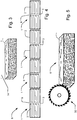
- Fig. 4 shows an embodiment of a slab of insulation 6 that has been cut into a number of lamellas 1, and each of the lamellas 1 has furthermore been divided into two lamella parts 2 by cutting a split 9, almost all the way through the slab 6, leaving a thin neck 3.
- the part of the slab 6 where the thin neck is located can be of another material than the rest of the slab 6 or be with another structure of the same kind of material to provide any one of the configurations of the thin neck 3 described in the above.
- Fig. 5 it is shown how the slab of insulation 6 can be cut into lamellas 1 and how the lamellas 1 are divided into lamella parts 2 by using a circular saw 30 making a partial cut in the form of a split 9. Other means of cutting may be used as well.
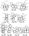
- Figs 6A-C shows a first embodiment of a tapered lamella.
- the lamella 1 is not tapered in its folded state as can be seen in Fig. 6A .
- the insulation lamella 1 is provided with a split 9 along the length 14 of the insulation lamella 1 at an angle to a base layer 20 where in this embodiment the lamella has been placed in its folded state.
- the lamella parts 2a and 2b has two first sides 4a and 4b opposing the second sides 5a and 5b. At side 4b and the opposing side 5b it is indicated how the two opposite sides of the lamella part 2b is arranged with an inclination ⁇ .
- the lamella parts 2a and 2b are each turned 90 degrees with the centre of rotation being the thin neck 3 that connects the two lamella parts. Also shown are the two first sides 4a and 4b and the opposing the second sides 5a and 5b.
- a tapered lamella 1 In its unfolded state in Fig. 6C this results in a tapered lamella 1, having sloping top side 16, with the inclination ⁇ in relation to the base side 15 of the lamella 1 that may be used for creating a sloping opposing top surface 19 of the insulation lamella structure 11 (cf. Fig 9 ).
- a first outermost edge 17a and a second outermost edge 17b are present on each insulation lamella 1.
- Each outermost edge 17a, 17b extends in the longitudinal direction of each insulation lamella 1, i.e. along the length 14.
- reference numeral 8 indicates that the two outermost edges 17a, 17b are adapted to be cut along the length of the lamella to provide a chamfered or filleted edge, in the following referred to as chamfered edge 8.
- chamfered edge 8 indicates that the two outermost edges 17a, 17b are adapted to be cut along the length of the lamella to provide a chamfered or filleted edge, in the following referred to as chamfered edge 8.
- chamfered edge 8 indicates that the two outermost edges 17a, 17b are adapted to be cut along the length of the lamella to provide a chamfered or filleted edge, in the following referred to as chamfered edge 8.
- Figs 7A-C show a second embodiment of a lamella 1 being tapered in its unfolded state.
- One lamella part 2b is rotated 180 degrees in relation to the base plane BP(x,y) on the base layer 20, where in this embodiment the lamella 1 has been placed in its folded state.
- the lamella part sides 4a, 4b that faced each other and that were created by the cutting of split 9 are now positioned with an inclination to the base plane facing away from the base layer 20.
- the cleft 10 is positioned perpendicularly to the upper surface of the base layer 20 facing downwards in the unfolded state.
- the insulation lamella 1 of the second embodiment comprises top side 16 and base side 15.
- the outermost edges 17a and 17b here adapted to form the chamfered edges 8, were in the folded state situated along the split 9 in that the outermost edges 17a, 17b were created by the partial inclined cut, which created the inclined split 9.
- the chamfered edges 8 are positioned at the upper edges along the length of the lamella 1 in the unfolded state resulting in an air channel 24 (cf. Figs 15A and 15B ), cf. in this regard Figs 6C and 7C .
- Figs 8A-D show a third embodiment of an insulation lamella 1 being tapered in its unfolded state.
- Fig. 8A shows the lamella 1 in a folded state, the lamella standing upright on a supporting base layer 20 with the side 5a facing the base layer and the opposing side 4a facing an inclined cut constituting a first split 9a.
- the side 4a is provided with an inclination in relation to side 5a.
- the lamella 1 is in addition to the inclined first split 9a, provided with a second split 9b parallel to the side 5a.
- the split 9b is cut from the opposite side 21 b than where the inclined cut creating split 9a opens on to, i.e.
- Fig. 8B it can be seen how the first lamella part 2a remains at the same position, lamella part 2b rotates 180 degrees with the centre of rotation being the thin neck 3a between lamella part 2a and lamella part 2b, and the third lamella part 2c is not rotated but merely positioned on the supporting base layer as lamella part 2b rotates 180 degrees in relation to lamella part 2c, around the thin neck 3b.
- the lamella part 2c is furthermore provided with a tapered face positioned parallel to or substantially parallel to the partial cut at the first split 9a.
- the lamella 1 is provided with first and second outermost edges 17a and 17b, in the embodiment shown adapted to be filleted or chamfered as indicated by reference numeral 8 to provide chamfered edges 8.
- one chamfered edge 8 positioned along the length of the lamella 1 is provided at the outermost edge 17a of the lamella 1 at the surface 16 facing upwards in the unfolded state, while the other two chamfered edges 8 are facing each other in the cleft 10 creating an air channel 24 (cf. Figs.15A and 15B ).
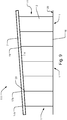
- Fig. 9 shows the insulation lamella 1 shown in Figs. 7A-C used in an insulation lamella structure 11, where an inclined opposing top surface 19 is created.
- the second, or middle, and third, or right-hand, lamellas 1 as compared to the first, or left-hand, lamella 1 in Fig. 7A have been made successively taller.
- lamella parts designated 2 are made successively taller in the height direction, or wider as the case is in the embodiment in Figs. 6A-C merely because of its orientation in relation to the base plane BP(x,y) or supporting base layer 20 when placed on said layer 20 in a folded state.
- Fig. 10 shows an alternative embodiment of an insulation lamella 1 having an inclining top side 16. Also the base side 15, the length 14, the width 12 and first and second outermost edges 17a and 17b are shown in order to indicate the general configuration of a tapered lamella 1.
- Fig. 11A-C the partial cut to form split 9 in the lamella 1 has been made either perpendicular to or parallel to the base plane BP(x,y) here placed on the upper surface of the base layer 20, depending on the orientation of the lamella 1 on the base layer 20, however the cut 9 has been positioned slightly off the middle on the lamella 1, resulting in lamella parts 2a and 2b of different sizes in the width direction, shown by distance 12a and 12b being unequal.
- a stepwise inclining top side 16 and top surface 19 of the insulation lamella structure 11 is attained through a difference in distance 23 formed by the difference in height between the base side 15 and second outermost edge 17b on one hand, and the base side 15 and an outermost edge 17c protruding at the middle of the lamella 1 and constituting the first outermost edge in terms of defining the inclination, on the other.
- the outermost edge 17c is here located in the same distance from the base side 15 as the outermost edge 17a.
- a separate top plate or pressure distributing board 7 is supported by the edges 17b and 17c such that the insulation lamella structure 11 and the pressure distributing board 7 together form the insulation structure 111.
- the pressure distributing board 7 is provided separately from the insulation lamella structure 11 and is positioned on top of the lamellas 1 to cover them substantially completely. Hence, the pressure distributing board 7 acts as a loose cover of the insulation lamella structure 11 and has an inclination corresponding to the top surface 19 of the insulation lamella structure 11, although displacing the inclination ⁇ in relation to the base plane BP(x,y).
- the hollow space between the stepwise inclining top surface 19 and the top plate in the form of pressure distributing board 7, forms a series of air channels 24.
- the edges 17b and 17c can be cut for example by chamfering in an angle corresponding the inclination ⁇ , hence supporting the pressure distributing board 7 with a larger area of the top side 16 and having air channels with a lesser cross-sectional area.
- the height of the insulation lamellas forming the lamella structure may be 200-500 mm, preferably between 300-400 mm to achieve a U-value below 0.12 W/m 2 K of the roof construction.
- the properties, dimensions and choice of material of the pressure distributing board 7 are chosen according to the specific needs and requirements of the intended field of application of the insulation structure.
- the pressure distributing board 7 is of a fibrous material such as stone wool or glass wool, preferably glass wool as this is easier to cut.
- the fibres in the board can be stretched and in a substantially laminated structure or it could more preferably be crimped with a wave-formed structure adding compressive strength to the plate for better walkability.
- the thickness may for instance lie between 10-200 mm, preferably 15-50 mm, more preferably 20-30 mm.
- the compressive strength typically lies in the range of 30-70kPa, preferably 40-70 kPa.
- the pressure distributing board 7 should cover all of the insulation lamella structure 11 in the finished insulation structure 111.
- Fig. 12 shows an embodiment of an insulation structure making use of the insulation lamella structure 11 according to the invention, in which the separate pressure distributing board 7 is removed for reasons of clearness in reading the drawings, typically representing a situation in which the pressure distributing board 7 has not yet been mounted.
- a number of lamellas 1 have been arranged in rows 25. Viewing the drawing from left to right, the first six rows 25 of lamellas 1 form a first section positioned on the base plane BP(x,y), i.e. directly on the supporting base layer 20.
- the next six rows 25 of lamellas 1 forming the second section are positioned on top of a plane layer 26a of insulation, and the further next six rows 25 forming the third section of lamellas 1 are positioned on top of two plane layers 26a and 26b of insulation of equal thickness.
- the six last rows 25 of lamellas 1 forming a fourth section of rows 25 are positioned on top of two plane layers 26a and 26c of insulation of unequal thickness. This provides a continuously inclining opposing surface 19 across several lamellas 1.
- the plane layers 26a, 26b, 26c of insulation may be made of other materials than insulation, as long as the different in height and the support is provided to the lamellas 1.
- a further feature apparent from this Figure is the configuration of the insulation lamella structure 11 in that the lamellas 1 form a staggered pattern, where every second row 25 of lamella 1 is offset lengthwise in relation the adjacent row 25.
- the staggered pattern can be obtained by only two lamellas being of different length, being of same length and offset lengthwise or being of different length with a lengthwise offset displacement.
- the lamellas 1 are lengthwise running across the inclination ⁇ created by the lamellas that have been cut at an angle in relation to the base plane and base layer 20 and are typically provided as in the embodiments shown in Figs 6, 7 or 8 .
- the first and the second outermost edges extends along the length of the insulation lamella.
- the length of the insulation lamella is preferably longer than it is wide and longer than it is high.
- the staggered pattern is preferably provided by having insulation lamellas offset in relation to each other along the length of the insulation lamellas or by having a difference in the length of the insulation lamellas. This provides better production tolerances on the length of the lamella. Length tolerances for installing in a staggered pattern can be very coarse, making the lamellas easier to produce, with length cutting techniques fit for mass production, and with less unplanned interruptions of production.
- the number of different lamellas 1 may be limited, and the size of the lamellas 1 will not get difficult to handle.
- the insulation lamella structure 11 is here provided with an opening 13, for example for a skylight or a chimney. Because the insulation lamella structure 11 forms a staggered pattern across the inclination ⁇ there is less waste as the pieces 27 of lamellas 1 that have been cut off to make room for the opening 13, can be used on the other and opposing side of the opening 13.
- Figs 13A-D show an embodiment of an insulation lamella 1 provided with ventilation channels 24.
- the lamella is seen from two different sides.
- the split 9 is facing upwards and in Fig. 13B the split 9 is facing downwards.
- Both figures show the lamella 1 in a folded state.
- Both lamella parts 2 are provided with chamfered edges 8 extending along the edge of the lamella 1, and two air channel recesses 22 positioned substantially opposite each other, substantially perpendicularly to the length 14 and the base plane BP(x,y).
- the two air channel recesses 22 are shown as located more or less accurately opposite each other, slight variations in the positions do not hinder the air channel from functioning, even if the recess placing should drift a bit.
- Figs. 14A-B shows an embodiment of an insulation lamella structure 11 in an insulation structure 111 provided with ventilation channels 24 as seen from the front and from the side, respectively.
- the air channels 24 are formed by either the chamfered edges 8 of two lamellas 1 placed side-by-side ( Fig. 14A ) or by the recess 22 in the lamella part 2.
- the recesses 22 can be formed by other geometry of the cross-sectional area and there can be more recesses 22 per lamella 1.
- insulation lamellas 1 with tapered lamella parts 2 have been used.
- the lamellas have been covered with a pressure distributing board 7.
- the lamella parts 2 are positioned on a substantially horizontal base layer 20, where the inclining side 16 of the lamella 1 is facing upwards, creating a sloping opposing surface 19, such as a roof surface.
- a sloping opposing surface 19 such as a roof surface.
- the separate pressure distributing board 7 On top of the lamella parts 2 the separate pressure distributing board 7 has been placed.
- the lamella parts 2 are being made successively taller or wider depending on the lamella's 1 orientation in relation to the base plane BP(x,y) on the supporting base layer 20. Because of the inclined partial cut in relation to the base plane or supporting base layer 20 the sloping or inclining opposing top surface 19 is continuous.
- Fig. 15A shows an embodiment of an insulation lamella structure 11 in an insulation structure 111 provided with ventilation channels 24 as seen from above.
- the air channels 24 are extending both along the inclination, established by air channel recesses 22, and across the inclination, constituted by chamfered edges 8, of the insulation lamella structure 11.
- the insulation lamella structure 11 forms a staggered pattern, and the grid of air channels 24 can be seen as the punctured lines.
- Fig. 15B shows an embodiment of a similar insulation structure 111 as in Fig. 15A , as seen from above.
- the insulation structure 111 has been provided with openings 13, such as protruding elements in the form of chimneys, ventilation hoods, skylights or the like.
- the insulation lamellas 1 that have been cut off, may be used on the other side of the interrupting element 13 due to the staggered pattern of the insulation structure 111.
- insulation lamella and lamella are both used for the same element. The same applies to supporting base layer and base layer.
Landscapes
- Engineering & Computer Science (AREA)
- Architecture (AREA)
- Civil Engineering (AREA)
- Structural Engineering (AREA)
- Building Environments (AREA)
Priority Applications (5)
| Application Number | Priority Date | Filing Date | Title |
|---|---|---|---|
| EP17184086.1A EP3438367A1 (fr) | 2017-07-31 | 2017-07-31 | Structure lamellaire isolante à lamelles fendues et son procédé d'installation |
| DK18185477.9T DK3438369T3 (da) | 2017-07-31 | 2018-07-25 | Isoleringslamelstruktur med spaltede lameller og fremgangsmåde til at installere samme. |
| PL18185477T PL3438369T3 (pl) | 2017-07-31 | 2018-07-25 | Izolacyjna konstrukcja płytowa z rozdzielonymi płytami i sposób jej montażu |
| EP18185477.9A EP3438369B1 (fr) | 2017-07-31 | 2018-07-25 | Structure lamellaire isolante à lamelles fendues et son procédé d'installation |
| RU2018127770A RU2788373C2 (ru) | 2017-07-31 | 2018-07-30 | Теплоизолирующая ламельная конструкция с разделенными ламелями и способ ее установки |
Applications Claiming Priority (1)
| Application Number | Priority Date | Filing Date | Title |
|---|---|---|---|
| EP17184086.1A EP3438367A1 (fr) | 2017-07-31 | 2017-07-31 | Structure lamellaire isolante à lamelles fendues et son procédé d'installation |
Publications (1)
| Publication Number | Publication Date |
|---|---|
| EP3438367A1 true EP3438367A1 (fr) | 2019-02-06 |
Family
ID=59506117
Family Applications (2)
| Application Number | Title | Priority Date | Filing Date |
|---|---|---|---|
| EP17184086.1A Withdrawn EP3438367A1 (fr) | 2017-07-31 | 2017-07-31 | Structure lamellaire isolante à lamelles fendues et son procédé d'installation |
| EP18185477.9A Active EP3438369B1 (fr) | 2017-07-31 | 2018-07-25 | Structure lamellaire isolante à lamelles fendues et son procédé d'installation |
Family Applications After (1)
| Application Number | Title | Priority Date | Filing Date |
|---|---|---|---|
| EP18185477.9A Active EP3438369B1 (fr) | 2017-07-31 | 2018-07-25 | Structure lamellaire isolante à lamelles fendues et son procédé d'installation |
Country Status (3)
| Country | Link |
|---|---|
| EP (2) | EP3438367A1 (fr) |
| DK (1) | DK3438369T3 (fr) |
| PL (1) | PL3438369T3 (fr) |
Cited By (1)
| Publication number | Priority date | Publication date | Assignee | Title |
|---|---|---|---|---|
| US12258761B2 (en) | 2023-04-19 | 2025-03-25 | Bmic Llc | Roofing system having tapered insulation panels, a roof assembly kit and a method of installing thereof |
Citations (8)
| Publication number | Priority date | Publication date | Assignee | Title |
|---|---|---|---|---|
| US4379381A (en) * | 1980-06-05 | 1983-04-12 | Emerson H. Mizell | Roof insulation system |
| EP0133083B1 (fr) | 1983-07-07 | 1988-03-02 | Isover Saint-Gobain | Formation de feutres à structure isotrope |
| DE9213220U1 (de) * | 1992-10-01 | 1992-12-03 | J. u. Otto Krebber GmbH, 4200 Oberhausen | Dämmbahn |
| US6105324A (en) * | 1997-10-23 | 2000-08-22 | Atlas Roofing Corporation | Foldable roof panel unit and method of installation |
| DE10101929A1 (de) * | 2001-01-16 | 2002-09-19 | Pfleiderer Daemmstofftechnik | Aufsparrendämmsystem sowie Verfahren zur Aufsparrendämmung eines mit einer Dacheindeckung eingedeckten Daches |
| DE202005016852U1 (de) * | 2005-10-04 | 2006-02-09 | Mayer, Helmut | System für die Gebäudebelüftung im Bereich der Durchführung eines Installationsrohrs durch ein Flachdach |
| EP2757208A1 (fr) | 2013-01-16 | 2014-07-23 | Paroc Oy Ab | Procédé de production de couches d'isolation pour laine minérale |
| US9249571B1 (en) * | 2011-07-13 | 2016-02-02 | Arthur Paul White | Insulating system |
-
2017
- 2017-07-31 EP EP17184086.1A patent/EP3438367A1/fr not_active Withdrawn
-
2018
- 2018-07-25 PL PL18185477T patent/PL3438369T3/pl unknown
- 2018-07-25 DK DK18185477.9T patent/DK3438369T3/da active
- 2018-07-25 EP EP18185477.9A patent/EP3438369B1/fr active Active
Patent Citations (8)
| Publication number | Priority date | Publication date | Assignee | Title |
|---|---|---|---|---|
| US4379381A (en) * | 1980-06-05 | 1983-04-12 | Emerson H. Mizell | Roof insulation system |
| EP0133083B1 (fr) | 1983-07-07 | 1988-03-02 | Isover Saint-Gobain | Formation de feutres à structure isotrope |
| DE9213220U1 (de) * | 1992-10-01 | 1992-12-03 | J. u. Otto Krebber GmbH, 4200 Oberhausen | Dämmbahn |
| US6105324A (en) * | 1997-10-23 | 2000-08-22 | Atlas Roofing Corporation | Foldable roof panel unit and method of installation |
| DE10101929A1 (de) * | 2001-01-16 | 2002-09-19 | Pfleiderer Daemmstofftechnik | Aufsparrendämmsystem sowie Verfahren zur Aufsparrendämmung eines mit einer Dacheindeckung eingedeckten Daches |
| DE202005016852U1 (de) * | 2005-10-04 | 2006-02-09 | Mayer, Helmut | System für die Gebäudebelüftung im Bereich der Durchführung eines Installationsrohrs durch ein Flachdach |
| US9249571B1 (en) * | 2011-07-13 | 2016-02-02 | Arthur Paul White | Insulating system |
| EP2757208A1 (fr) | 2013-01-16 | 2014-07-23 | Paroc Oy Ab | Procédé de production de couches d'isolation pour laine minérale |
Cited By (1)
| Publication number | Priority date | Publication date | Assignee | Title |
|---|---|---|---|---|
| US12258761B2 (en) | 2023-04-19 | 2025-03-25 | Bmic Llc | Roofing system having tapered insulation panels, a roof assembly kit and a method of installing thereof |
Also Published As
| Publication number | Publication date |
|---|---|
| PL3438369T3 (pl) | 2022-01-03 |
| RU2018127770A3 (fr) | 2021-12-02 |
| EP3438369A1 (fr) | 2019-02-06 |
| RU2018127770A (ru) | 2020-02-03 |
| EP3438369B1 (fr) | 2021-09-29 |
| DK3438369T3 (da) | 2021-12-20 |
Similar Documents
| Publication | Publication Date | Title |
|---|---|---|
| US4446661A (en) | Spacer means for providing air gaps | |
| US4446664A (en) | Insulation system | |
| EP3438370B1 (fr) | Structure d'isolation inclinable et son procédé d'installation | |
| EP3438367A1 (fr) | Structure lamellaire isolante à lamelles fendues et son procédé d'installation | |
| EP0435942B1 (fr) | Isolation de toits plats et construction simultanee d'une pente destinee au drainage positif de la toiture couvrant l'isolation | |
| GB2092202A (en) | Overroofing of buildings | |
| US6860076B2 (en) | Covering arrangement for a building, and covering part for use in such a covering arrangement | |
| JP6093798B2 (ja) | 垂木の継手構造 | |
| EP0795659A1 (fr) | Construction de toit | |
| RU2788373C2 (ru) | Теплоизолирующая ламельная конструкция с разделенными ламелями и способ ее установки | |
| RU2774529C2 (ru) | Наклонная теплоизолирующая конструкция и способ ее установки | |
| US10697180B2 (en) | Method for heat insulating a building surface and an insulation board therefor | |
| JP2011226231A (ja) | 屋根葺き構造及び屋根材 | |
| GB2243169A (en) | Corrugated edged roofing felt | |
| JP6823904B2 (ja) | 折板屋根材を用いた緩勾配屋根の施工方法 | |
| JP7795351B2 (ja) | 屋根構造 | |
| EP4417763A1 (fr) | Ensemble de colliers de sous-toiture et procédé pour sceller un joint entre un groupe de fenêtres de toit montées dans une structure de toit et un sous-toiture | |
| JP7744005B2 (ja) | 屋根の防水断熱構造とその施工方法 | |
| EP2923007B1 (fr) | Toitures inclinées en tuiles | |
| JP3176950U (ja) | 屋根葺き替え構造 | |
| JP5485113B2 (ja) | 防水シート付きラス及びその製造方法 | |
| CN216239265U (zh) | 屋顶下方片材和建筑物的屋顶结构 | |
| EP1645698A1 (fr) | Une structure de toit | |
| GB2450801A (en) | A moisture barrier, and a method for placing it between roof element and a cavity wall. | |
| JPH0259895B2 (fr) |
Legal Events
| Date | Code | Title | Description |
|---|---|---|---|
| PUAI | Public reference made under article 153(3) epc to a published international application that has entered the european phase |
Free format text: ORIGINAL CODE: 0009012 |
|
| AK | Designated contracting states |
Kind code of ref document: A1 Designated state(s): AL AT BE BG CH CY CZ DE DK EE ES FI FR GB GR HR HU IE IS IT LI LT LU LV MC MK MT NL NO PL PT RO RS SE SI SK SM TR |
|
| AX | Request for extension of the european patent |
Extension state: BA ME |
|
| STAA | Information on the status of an ep patent application or granted ep patent |
Free format text: STATUS: THE APPLICATION IS DEEMED TO BE WITHDRAWN |
|
| 18D | Application deemed to be withdrawn |
Effective date: 20190807 |