EP3438432A1 - Katalysatordiagnosevorrichtung - Google Patents
Katalysatordiagnosevorrichtung Download PDFInfo
- Publication number
- EP3438432A1 EP3438432A1 EP16896800.6A EP16896800A EP3438432A1 EP 3438432 A1 EP3438432 A1 EP 3438432A1 EP 16896800 A EP16896800 A EP 16896800A EP 3438432 A1 EP3438432 A1 EP 3438432A1
- Authority
- EP
- European Patent Office
- Prior art keywords
- catalyst
- afr
- elapsed time
- basis
- oxygen storage
- Prior art date
- Legal status (The legal status is an assumption and is not a legal conclusion. Google has not performed a legal analysis and makes no representation as to the accuracy of the status listed.)
- Withdrawn
Links
Images



Classifications
-
- F—MECHANICAL ENGINEERING; LIGHTING; HEATING; WEAPONS; BLASTING
- F02—COMBUSTION ENGINES; HOT-GAS OR COMBUSTION-PRODUCT ENGINE PLANTS
- F02D—CONTROLLING COMBUSTION ENGINES
- F02D41/00—Electrical control of supply of combustible mixture or its constituents
- F02D41/02—Circuit arrangements for generating control signals
- F02D41/14—Introducing closed-loop corrections
- F02D41/1438—Introducing closed-loop corrections using means for determining characteristics of the combustion gases; Sensors therefor
- F02D41/1444—Introducing closed-loop corrections using means for determining characteristics of the combustion gases; Sensors therefor characterised by the characteristics of the combustion gases
- F02D41/1454—Introducing closed-loop corrections using means for determining characteristics of the combustion gases; Sensors therefor characterised by the characteristics of the combustion gases the characteristics being an oxygen content or concentration or the air-fuel ratio
- F02D41/1458—Introducing closed-loop corrections using means for determining characteristics of the combustion gases; Sensors therefor characterised by the characteristics of the combustion gases the characteristics being an oxygen content or concentration or the air-fuel ratio with determination means using an estimation
-
- B—PERFORMING OPERATIONS; TRANSPORTING
- B01—PHYSICAL OR CHEMICAL PROCESSES OR APPARATUS IN GENERAL
- B01D—SEPARATION
- B01D53/00—Separation of gases or vapours; Recovering vapours of volatile solvents from gases; Chemical or biological purification of waste gases, e.g. engine exhaust gases, smoke, fumes, flue gases, aerosols
- B01D53/34—Chemical or biological purification of waste gases
- B01D53/92—Chemical or biological purification of waste gases of engine exhaust gases
- B01D53/94—Chemical or biological purification of waste gases of engine exhaust gases by catalytic processes
- B01D53/9445—Simultaneously removing carbon monoxide, hydrocarbons or nitrogen oxides making use of three-way catalysts [TWC] or four-way-catalysts [FWC]
- B01D53/9454—Simultaneously removing carbon monoxide, hydrocarbons or nitrogen oxides making use of three-way catalysts [TWC] or four-way-catalysts [FWC] characterised by a specific device
-
- F—MECHANICAL ENGINEERING; LIGHTING; HEATING; WEAPONS; BLASTING
- F01—MACHINES OR ENGINES IN GENERAL; ENGINE PLANTS IN GENERAL; STEAM ENGINES
- F01N—GAS-FLOW SILENCERS OR EXHAUST APPARATUS FOR MACHINES OR ENGINES IN GENERAL; GAS-FLOW SILENCERS OR EXHAUST APPARATUS FOR INTERNAL-COMBUSTION ENGINES
- F01N11/00—Monitoring or diagnostic devices for exhaust-gas treatment apparatus
-
- F—MECHANICAL ENGINEERING; LIGHTING; HEATING; WEAPONS; BLASTING
- F01—MACHINES OR ENGINES IN GENERAL; ENGINE PLANTS IN GENERAL; STEAM ENGINES
- F01N—GAS-FLOW SILENCERS OR EXHAUST APPARATUS FOR MACHINES OR ENGINES IN GENERAL; GAS-FLOW SILENCERS OR EXHAUST APPARATUS FOR INTERNAL-COMBUSTION ENGINES
- F01N11/00—Monitoring or diagnostic devices for exhaust-gas treatment apparatus
- F01N11/007—Monitoring or diagnostic devices for exhaust-gas treatment apparatus the diagnostic devices measuring oxygen or air concentration downstream of the exhaust apparatus
-
- F—MECHANICAL ENGINEERING; LIGHTING; HEATING; WEAPONS; BLASTING
- F01—MACHINES OR ENGINES IN GENERAL; ENGINE PLANTS IN GENERAL; STEAM ENGINES
- F01N—GAS-FLOW SILENCERS OR EXHAUST APPARATUS FOR MACHINES OR ENGINES IN GENERAL; GAS-FLOW SILENCERS OR EXHAUST APPARATUS FOR INTERNAL-COMBUSTION ENGINES
- F01N3/00—Exhaust or silencing apparatus having means for purifying, rendering innocuous, or otherwise treating exhaust
- F01N3/08—Exhaust or silencing apparatus having means for purifying, rendering innocuous, or otherwise treating exhaust for rendering innocuous
- F01N3/10—Exhaust or silencing apparatus having means for purifying, rendering innocuous, or otherwise treating exhaust for rendering innocuous by thermal or catalytic conversion of noxious components of exhaust
- F01N3/101—Three-way catalysts
-
- F—MECHANICAL ENGINEERING; LIGHTING; HEATING; WEAPONS; BLASTING
- F02—COMBUSTION ENGINES; HOT-GAS OR COMBUSTION-PRODUCT ENGINE PLANTS
- F02D—CONTROLLING COMBUSTION ENGINES
- F02D41/00—Electrical control of supply of combustible mixture or its constituents
- F02D41/02—Circuit arrangements for generating control signals
- F02D41/021—Introducing corrections for particular conditions exterior to the engine
- F02D41/0235—Introducing corrections for particular conditions exterior to the engine in relation with the state of the exhaust gas treating apparatus
-
- F—MECHANICAL ENGINEERING; LIGHTING; HEATING; WEAPONS; BLASTING
- F02—COMBUSTION ENGINES; HOT-GAS OR COMBUSTION-PRODUCT ENGINE PLANTS
- F02D—CONTROLLING COMBUSTION ENGINES
- F02D41/00—Electrical control of supply of combustible mixture or its constituents
- F02D41/02—Circuit arrangements for generating control signals
- F02D41/021—Introducing corrections for particular conditions exterior to the engine
- F02D41/0235—Introducing corrections for particular conditions exterior to the engine in relation with the state of the exhaust gas treating apparatus
- F02D41/027—Introducing corrections for particular conditions exterior to the engine in relation with the state of the exhaust gas treating apparatus to purge or regenerate the exhaust gas treating apparatus
-
- F—MECHANICAL ENGINEERING; LIGHTING; HEATING; WEAPONS; BLASTING
- F02—COMBUSTION ENGINES; HOT-GAS OR COMBUSTION-PRODUCT ENGINE PLANTS
- F02D—CONTROLLING COMBUSTION ENGINES
- F02D41/00—Electrical control of supply of combustible mixture or its constituents
- F02D41/02—Circuit arrangements for generating control signals
- F02D41/021—Introducing corrections for particular conditions exterior to the engine
- F02D41/0235—Introducing corrections for particular conditions exterior to the engine in relation with the state of the exhaust gas treating apparatus
- F02D41/0295—Control according to the amount of oxygen that is stored on the exhaust gas treating apparatus
-
- F—MECHANICAL ENGINEERING; LIGHTING; HEATING; WEAPONS; BLASTING
- F02—COMBUSTION ENGINES; HOT-GAS OR COMBUSTION-PRODUCT ENGINE PLANTS
- F02D—CONTROLLING COMBUSTION ENGINES
- F02D41/00—Electrical control of supply of combustible mixture or its constituents
- F02D41/02—Circuit arrangements for generating control signals
- F02D41/14—Introducing closed-loop corrections
- F02D41/1438—Introducing closed-loop corrections using means for determining characteristics of the combustion gases; Sensors therefor
- F02D41/1439—Introducing closed-loop corrections using means for determining characteristics of the combustion gases; Sensors therefor characterised by the position of the sensor
- F02D41/1441—Plural sensors
-
- F—MECHANICAL ENGINEERING; LIGHTING; HEATING; WEAPONS; BLASTING
- F02—COMBUSTION ENGINES; HOT-GAS OR COMBUSTION-PRODUCT ENGINE PLANTS
- F02D—CONTROLLING COMBUSTION ENGINES
- F02D41/00—Electrical control of supply of combustible mixture or its constituents
- F02D41/02—Circuit arrangements for generating control signals
- F02D41/14—Introducing closed-loop corrections
- F02D41/1438—Introducing closed-loop corrections using means for determining characteristics of the combustion gases; Sensors therefor
- F02D41/1444—Introducing closed-loop corrections using means for determining characteristics of the combustion gases; Sensors therefor characterised by the characteristics of the combustion gases
- F02D41/1454—Introducing closed-loop corrections using means for determining characteristics of the combustion gases; Sensors therefor characterised by the characteristics of the combustion gases the characteristics being an oxygen content or concentration or the air-fuel ratio
-
- F—MECHANICAL ENGINEERING; LIGHTING; HEATING; WEAPONS; BLASTING
- F02—COMBUSTION ENGINES; HOT-GAS OR COMBUSTION-PRODUCT ENGINE PLANTS
- F02D—CONTROLLING COMBUSTION ENGINES
- F02D41/00—Electrical control of supply of combustible mixture or its constituents
- F02D41/02—Circuit arrangements for generating control signals
- F02D41/14—Introducing closed-loop corrections
- F02D41/1438—Introducing closed-loop corrections using means for determining characteristics of the combustion gases; Sensors therefor
- F02D41/1444—Introducing closed-loop corrections using means for determining characteristics of the combustion gases; Sensors therefor characterised by the characteristics of the combustion gases
- F02D41/1454—Introducing closed-loop corrections using means for determining characteristics of the combustion gases; Sensors therefor characterised by the characteristics of the combustion gases the characteristics being an oxygen content or concentration or the air-fuel ratio
- F02D41/1456—Introducing closed-loop corrections using means for determining characteristics of the combustion gases; Sensors therefor characterised by the characteristics of the combustion gases the characteristics being an oxygen content or concentration or the air-fuel ratio with sensor output signal being linear or quasi-linear with the concentration of oxygen
-
- F—MECHANICAL ENGINEERING; LIGHTING; HEATING; WEAPONS; BLASTING
- F02—COMBUSTION ENGINES; HOT-GAS OR COMBUSTION-PRODUCT ENGINE PLANTS
- F02D—CONTROLLING COMBUSTION ENGINES
- F02D41/00—Electrical control of supply of combustible mixture or its constituents
- F02D41/02—Circuit arrangements for generating control signals
- F02D41/14—Introducing closed-loop corrections
- F02D41/1438—Introducing closed-loop corrections using means for determining characteristics of the combustion gases; Sensors therefor
- F02D41/1477—Introducing closed-loop corrections using means for determining characteristics of the combustion gases; Sensors therefor characterised by the regulation circuit or part of it,(e.g. comparator, PI regulator, output)
- F02D41/1479—Using a comparator with variable reference
-
- F—MECHANICAL ENGINEERING; LIGHTING; HEATING; WEAPONS; BLASTING
- F02—COMBUSTION ENGINES; HOT-GAS OR COMBUSTION-PRODUCT ENGINE PLANTS
- F02D—CONTROLLING COMBUSTION ENGINES
- F02D41/00—Electrical control of supply of combustible mixture or its constituents
- F02D41/30—Controlling fuel injection
- F02D41/3005—Details not otherwise provided for
-
- F—MECHANICAL ENGINEERING; LIGHTING; HEATING; WEAPONS; BLASTING
- F01—MACHINES OR ENGINES IN GENERAL; ENGINE PLANTS IN GENERAL; STEAM ENGINES
- F01N—GAS-FLOW SILENCERS OR EXHAUST APPARATUS FOR MACHINES OR ENGINES IN GENERAL; GAS-FLOW SILENCERS OR EXHAUST APPARATUS FOR INTERNAL-COMBUSTION ENGINES
- F01N2550/00—Monitoring or diagnosing the deterioration of exhaust systems
- F01N2550/02—Catalytic activity of catalytic converters
-
- F—MECHANICAL ENGINEERING; LIGHTING; HEATING; WEAPONS; BLASTING
- F01—MACHINES OR ENGINES IN GENERAL; ENGINE PLANTS IN GENERAL; STEAM ENGINES
- F01N—GAS-FLOW SILENCERS OR EXHAUST APPARATUS FOR MACHINES OR ENGINES IN GENERAL; GAS-FLOW SILENCERS OR EXHAUST APPARATUS FOR INTERNAL-COMBUSTION ENGINES
- F01N2560/00—Exhaust systems with means for detecting or measuring exhaust gas components or characteristics
- F01N2560/02—Exhaust systems with means for detecting or measuring exhaust gas components or characteristics the means being an exhaust gas sensor
- F01N2560/025—Exhaust systems with means for detecting or measuring exhaust gas components or characteristics the means being an exhaust gas sensor for measuring or detecting O2, e.g. lambda sensors
-
- F—MECHANICAL ENGINEERING; LIGHTING; HEATING; WEAPONS; BLASTING
- F01—MACHINES OR ENGINES IN GENERAL; ENGINE PLANTS IN GENERAL; STEAM ENGINES
- F01N—GAS-FLOW SILENCERS OR EXHAUST APPARATUS FOR MACHINES OR ENGINES IN GENERAL; GAS-FLOW SILENCERS OR EXHAUST APPARATUS FOR INTERNAL-COMBUSTION ENGINES
- F01N2900/00—Details of electrical control or of the monitoring of the exhaust gas treating apparatus
- F01N2900/06—Parameters used for exhaust control or diagnosing
- F01N2900/14—Parameters used for exhaust control or diagnosing said parameters being related to the exhaust gas
- F01N2900/1402—Exhaust gas composition
-
- F—MECHANICAL ENGINEERING; LIGHTING; HEATING; WEAPONS; BLASTING
- F01—MACHINES OR ENGINES IN GENERAL; ENGINE PLANTS IN GENERAL; STEAM ENGINES
- F01N—GAS-FLOW SILENCERS OR EXHAUST APPARATUS FOR MACHINES OR ENGINES IN GENERAL; GAS-FLOW SILENCERS OR EXHAUST APPARATUS FOR INTERNAL-COMBUSTION ENGINES
- F01N2900/00—Details of electrical control or of the monitoring of the exhaust gas treating apparatus
- F01N2900/06—Parameters used for exhaust control or diagnosing
- F01N2900/16—Parameters used for exhaust control or diagnosing said parameters being related to the exhaust apparatus, e.g. particulate filter or catalyst
- F01N2900/1624—Catalyst oxygen storage capacity
-
- F—MECHANICAL ENGINEERING; LIGHTING; HEATING; WEAPONS; BLASTING
- F02—COMBUSTION ENGINES; HOT-GAS OR COMBUSTION-PRODUCT ENGINE PLANTS
- F02D—CONTROLLING COMBUSTION ENGINES
- F02D2200/00—Input parameters for engine control
- F02D2200/02—Input parameters for engine control the parameters being related to the engine
- F02D2200/06—Fuel or fuel supply system parameters
- F02D2200/0614—Actual fuel mass or fuel injection amount
-
- F—MECHANICAL ENGINEERING; LIGHTING; HEATING; WEAPONS; BLASTING
- F02—COMBUSTION ENGINES; HOT-GAS OR COMBUSTION-PRODUCT ENGINE PLANTS
- F02D—CONTROLLING COMBUSTION ENGINES
- F02D2200/00—Input parameters for engine control
- F02D2200/02—Input parameters for engine control the parameters being related to the engine
- F02D2200/08—Exhaust gas treatment apparatus parameters
- F02D2200/0814—Oxygen storage amount
-
- F—MECHANICAL ENGINEERING; LIGHTING; HEATING; WEAPONS; BLASTING
- F02—COMBUSTION ENGINES; HOT-GAS OR COMBUSTION-PRODUCT ENGINE PLANTS
- F02D—CONTROLLING COMBUSTION ENGINES
- F02D2200/00—Input parameters for engine control
- F02D2200/02—Input parameters for engine control the parameters being related to the engine
- F02D2200/08—Exhaust gas treatment apparatus parameters
- F02D2200/0816—Oxygen storage capacity
-
- F—MECHANICAL ENGINEERING; LIGHTING; HEATING; WEAPONS; BLASTING
- F02—COMBUSTION ENGINES; HOT-GAS OR COMBUSTION-PRODUCT ENGINE PLANTS
- F02D—CONTROLLING COMBUSTION ENGINES
- F02D2200/00—Input parameters for engine control
- F02D2200/02—Input parameters for engine control the parameters being related to the engine
- F02D2200/10—Parameters related to the engine output, e.g. engine torque or engine speed
- F02D2200/101—Engine speed
-
- Y—GENERAL TAGGING OF NEW TECHNOLOGICAL DEVELOPMENTS; GENERAL TAGGING OF CROSS-SECTIONAL TECHNOLOGIES SPANNING OVER SEVERAL SECTIONS OF THE IPC; TECHNICAL SUBJECTS COVERED BY FORMER USPC CROSS-REFERENCE ART COLLECTIONS [XRACs] AND DIGESTS
- Y02—TECHNOLOGIES OR APPLICATIONS FOR MITIGATION OR ADAPTATION AGAINST CLIMATE CHANGE
- Y02T—CLIMATE CHANGE MITIGATION TECHNOLOGIES RELATED TO TRANSPORTATION
- Y02T10/00—Road transport of goods or passengers
- Y02T10/10—Internal combustion engine [ICE] based vehicles
- Y02T10/12—Improving ICE efficiencies
-
- Y—GENERAL TAGGING OF NEW TECHNOLOGICAL DEVELOPMENTS; GENERAL TAGGING OF CROSS-SECTIONAL TECHNOLOGIES SPANNING OVER SEVERAL SECTIONS OF THE IPC; TECHNICAL SUBJECTS COVERED BY FORMER USPC CROSS-REFERENCE ART COLLECTIONS [XRACs] AND DIGESTS
- Y02—TECHNOLOGIES OR APPLICATIONS FOR MITIGATION OR ADAPTATION AGAINST CLIMATE CHANGE
- Y02T—CLIMATE CHANGE MITIGATION TECHNOLOGIES RELATED TO TRANSPORTATION
- Y02T10/00—Road transport of goods or passengers
- Y02T10/10—Internal combustion engine [ICE] based vehicles
- Y02T10/40—Engine management systems
Definitions
- the present invention relates to a catalyst diagnosis device that diagnoses deterioration of a catalyst for purging exhaust gas of an engine on the basis of Air/fuel ratio (AFR) detected by a pair of sensors provided on an upstream side and on a downstream side thereof.
- AFR Air/fuel ratio
- a system provided with a catalyst in an exhaust system of an engine for purging exhaust gas is widely known.
- purging performance of the catalyst is deteriorated by long-term use, various methods for detecting the deterioration are proposed.
- a patent literature 1 discloses technique for executing active AFR control that transition from leanness to richness and transition from richness to leanness as to AFR of exhaust gas flowing into the catalyst are alternately repeated, integrating oxygen purge amounts on the basis of transition of the AFR of exhaust gas flowing into the catalyst, an exhaust flow rate and others in the transition to richness, integrating oxygen storage amounts on the basis of transition of the AFR of exhaust gas flowing into the catalyst, an exhaust flow rate and others in the transition to leanness and making catalyst deterioration diagnosis on the basis of each integrated value in a catalyst deterioration determination system that determines deterioration of an exhaust purge catalyst provided with an oxygen storage facility.
- Patent Document 1 Japanese Patent No. 5835478
- the oxygen purge amount and the oxygen storage amount respectively to be a capacity index of the catalyst are estimated on the basis of theoretical AFR (stoichiometry) and AFR detected on the upstream side of the catalyst.
- AFR saturation ratio
- the present invention provides a catalyst diagnosis device that enables precisely grasping a variation of AFR on the downstream side of a catalyst and enables diagnosing a deteriorated condition of the catalyst on the basis of the variation.
- the present invention has a following feature in a catalyst diagnosis device which is provided with each AFR sensor on an upstream side and on a downstream side of a catalyst provided in an exhaust passage of an engine and which determines deterioration of the catalyst on the basis of output of each AFR sensor.
- Fig. 1 is a block diagram showing an exhaust system 20 to which the present invention is applied and in Fig. 1 , application to a motorcycle is shown as an example.
- an intake pipe 56 provided with an injector 57 every cylinder is attached.
- a catalyzer 61 is coupled via an outlet pipe 60 and a muffler 26 is coupled to the downstream side of the catalyzer via an exhaust pipe 62.
- the catalyzer 61 houses a catalyst C for purging exhaust gas, and an AFR sensor 50u that detects AFR of exhaust gas and an 02 sensor 50d that detects oxygen concentration are attached on the upstream side and on the downstream side of the catalyzer.
- the AFR sensor 50u the 02 sensor or an LAF sensor can be used.
- the oxygen concentration sensor 50d the 02 sensor or the LAF sensor can be also used. When the 02 sensor is used, its output value is required to be converted to AFR.
- an AFR calculating section 11 calculates AFR of exhaust gas on the basis of output signals from the sensors 50u, 50d.
- a fuel injection quantity controller 12 controls a fuel injection quantity by controlling open time Tout of the injector 57.
- the fuel injection quantity controller 12 is provided with a diagnostic injection facility in addition to a normal injection facility for properly controlling the fuel injection quantity while a vehicle is driven.
- the diagnostic injection facility corrects the fuel injection quantity by increasing or decreasing the fuel injection quantity so that as to upstream AFR (AFRu) detected by the AFR sensor 50u, transition from richness to leanness and transition from leanness to richness are alternately repeated after making feedback control that AFR is to be reference AFR in a stoichiometric area only in a predetermined period in a catalytic diagnostic cycle.
- AFRu upstream AFR
- a timer 13 counts elapsed time Tosc (a generic name of Tosa and/or Topa) until downstream AFR (AFRd) detected by the downstream sensor 50d meets a predetermined threshold condition when the fuel injection quantity is corrected by increasing or decreasing it by the diagnostic injection facility of the fuel injection quantity controller 12 so that as to the AFRu, the transition from either of leanness or richness to the other is repeated with the stoichiometric area between the leanness and the richness as described later.
- Tosc a generic name of Tosa and/or Topa
- a ⁇ AFR calculating section 14 calculates difference ⁇ AFR between average values of AFRs detected by each sensor 50u, 50d in Tosc (Tosa, Topa).
- An Mfuel calculating section 15 calculates fuel weight Mfuel per cycle of the engine.
- An Ne calculating section 16 calculates an average value of the number of revolutions Ne of the engine E in Tosc and adopts the average value as Ne in catalytic diagnosis.
- An OSA calculating section 17 calculates an Oxygen Storage Amount (OSA) in a reducing atmosphere of the catalyst as a function of the ⁇ AFR, Mfuel, Ne and Tosa as described later.
- An OPA calculating section 18 calculates an Oxygen Purge Amount (OPA) in an oxidizing atmosphere of the catalyst as a function of the ⁇ AFR, Mfuel, Ne and Topa as described later.
- a deterioration diagnosing section 19 diagnoses a deteriorated condition of the catalyst C on the basis of at least one of the OSA and OPA.
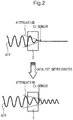
- Figs. 2 and 3 schematically represent a catalyst deterioration diagnosis method in the present invention.
- the fuel injection quantity is controlled so that as to the AFRu of the catalyst C, the transition from either of leanness or richness to the other is repeated, an oxygen content in exhaust gas is approximately fixedly held as shown in Fig. 2(a) if the catalyst C sufficiently functions and its oxygen storage facility and its oxygen purge facility are sufficiently exercised.
- HC hydrocarbon
- CO carbon monoxide
- the OSA and OPA of the catalyst C are estimated by comparing the AFRu and AFRd detected on the upstream side and on the downstream side of the catalyst C and it is diagnosed that when these are smaller than predetermined reference values, the catalyst C is deteriorated.
- Fig. 4 is a flowchart showing operation in one embodiment of the present invention.
- Fig. 5 is a flowchart showing a procedure for calculating OSC.
- Fig. 6 is a timing chart showing the operation in one embodiment of the present invention.
- a step S1 feedback control is applied to the fuel injection quantity by the fuel injection quantity controller 12 so that the AFRu of exhaust gas is maintained in an arbitrary reference AFR area.
- a range of ⁇ 5% as to 14.55 as ideal AFR is allowed as the reference AFR area.
- step S2 at time t1 shown in Fig. 6 , diagnostic injection in which correction of the fuel injection quantity by increasing or decreasing it is repeated in the predetermined cycle is started.
- the fuel injection quantity is corrected to be increased at first by switching an injection correction factor K of fuel and hereby, the AFRu is turned rich.
- a step S5 the AFRu and the AFRd are acquired and stored.
- the fuel injection quantity represented by Ne and Tout is acquired and stored.
- a step S7 it is determined whether the AFRd exceeds a predetermined OSA threshold or not.
- the process is returned to the step S5, and the acquisition and storage of the AFRu and AFRd and the acquisition and storage of the NE and Tout are repeated in a predetermined cycle.
- step S8 a value measured by the timer Tc is registered as OSA time Tosa and the timer Tc is reset.
- step S9 as described in detail later, OPA is calculated on the basis of the Tosa.
- a step S10 it is determined whether both the OSA and the OPA are already calculated or not. When either is not calculated yet, the process proceeds to a step S11 and it is determined whether the AFRu is turned rich or not.
- the injection quantity is switched to correction for increasing it again by the diagnostic injection facility, at time t4, the AFRu is turned from leanness to richness, and when the transition is detected in the step S11, the process proceeds to a step S12 and the timer Tc starts timing.
- a step S13 the AFRu and AFRd are acquired and stored.
- Ne and Tout are acquired and stored.
- a step S15 it is determined whether the AFRd is below a predetermined OPA threshold or not.
- the process is returned to the step S13, and the acquisition and storage of the AFRu and AFRd and the acquisition and storage of the NE and Tout are repeated in the predetermined cycle.
- the AFRd is equal to or below the OPA threshold and when this is detected in the step S15, the process proceeds to a step S16.
- a value measured by the timer Tc is registered as Topa and a count value of the timer Tc is reset.
- the OPA is calculated on the basis of the Topa.
- the elapsed time Tosc (Tosa and/or Topa) is acquired on the basis of the AFRd; however, the present invention is not limited to only this, and elapsed time may be also acquired on the basis of output voltage from the 02 sensor.
- each average value AFRu_ave, AFRd_ave of the AFRu and AFRd in an OSC period is calculated.
- each average value Ne_ave and Tout_ave of the NE and Tout in the OSC period is calculated.
- difference ⁇ AFR between the AFR on the upstream side and the AFR on the downstream side of the catalyst detected by each sensor 50u, 50d is calculated in the following expression (1).
- ⁇ AFR
- a step S34 fuel injection weight Mfuel per cycle is calculated on the basis of an integrated value of the Tout and an injection characteristic.
- a remaining oxygen content MO2 per cycle is calculated on the basis of the ⁇ AFR and the Mfuel per cycle.
- a mass flow rate M'O2 per second of remaining oxygen is calculated in the following expression (2).
- M ′ O 2 MO 2 ⁇ Ne / 120
- OSA and OPA are calculated in the following expressions (3), (4).
- step S10 when it is determined that both the OSA and the OPA are already calculated, the process proceeds to a step S17.
- step S17 a deteriorated condition of the catalyst is determined on the basis of the OSA and OPA.
- both the OSA and the OPA are below the predetermined reference values or either of them is below the reference value, it is diagnosed that the catalyst is deteriorated.
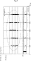
- Fig. 7 shows determination results of the OSA and OPA of measuring them in plural samples, varying a throttle angle with the Ne fixed and it can be verified that highly selective diagnostic results are acquired irrespective of an engine operational state.
- both the OSA and OPA as the OSC are calculated; however, only either may be calculated, and catalyst diagnosis may be also made on the basis of only either.
Landscapes
- Engineering & Computer Science (AREA)
- Chemical & Material Sciences (AREA)
- Combustion & Propulsion (AREA)
- Mechanical Engineering (AREA)
- General Engineering & Computer Science (AREA)
- Chemical Kinetics & Catalysis (AREA)
- Health & Medical Sciences (AREA)
- Materials Engineering (AREA)
- Toxicology (AREA)
- Analytical Chemistry (AREA)
- General Chemical & Material Sciences (AREA)
- Oil, Petroleum & Natural Gas (AREA)
- Environmental & Geological Engineering (AREA)
- Biomedical Technology (AREA)
- Exhaust Gas After Treatment (AREA)
- Electrical Control Of Air Or Fuel Supplied To Internal-Combustion Engine (AREA)
- Combined Controls Of Internal Combustion Engines (AREA)
Applications Claiming Priority (1)
| Application Number | Priority Date | Filing Date | Title |
|---|---|---|---|
| PCT/JP2016/060197 WO2017168580A1 (ja) | 2016-03-29 | 2016-03-29 | 触媒診断装置 |
Publications (2)
| Publication Number | Publication Date |
|---|---|
| EP3438432A1 true EP3438432A1 (de) | 2019-02-06 |
| EP3438432A4 EP3438432A4 (de) | 2019-04-17 |
Family
ID=59962706
Family Applications (1)
| Application Number | Title | Priority Date | Filing Date |
|---|---|---|---|
| EP16896800.6A Withdrawn EP3438432A4 (de) | 2016-03-29 | 2016-03-29 | Katalysatordiagnosevorrichtung |
Country Status (6)
| Country | Link |
|---|---|
| US (1) | US10774767B2 (de) |
| EP (1) | EP3438432A4 (de) |
| JP (1) | JP6611397B2 (de) |
| CN (1) | CN108884774B (de) |
| BR (1) | BR112018069649B1 (de) |
| WO (1) | WO2017168580A1 (de) |
Cited By (2)
| Publication number | Priority date | Publication date | Assignee | Title |
|---|---|---|---|---|
| FR3101667A1 (fr) * | 2019-10-02 | 2021-04-09 | Psa Automobiles Sa | Procédé de commande d’une boite de vitesse pour une mesure de diagnostic dans une plage de régime moteur prédéterminée |
| WO2022167736A1 (fr) * | 2021-02-08 | 2022-08-11 | Psa Automobiles Sa | Procédé de régulation du fonctionnement d'un catalyseur de gaz d'échappement produits par le moteur thermique d'un véhicule automobile |
Families Citing this family (5)
| Publication number | Priority date | Publication date | Assignee | Title |
|---|---|---|---|---|
| JP7151696B2 (ja) * | 2019-12-25 | 2022-10-12 | トヨタ自動車株式会社 | 触媒劣化検出装置 |
| JP7372440B2 (ja) * | 2020-03-05 | 2023-10-31 | 本田技研工業株式会社 | 触媒劣化診断装置 |
| CN115956001A (zh) * | 2020-10-29 | 2023-04-11 | 日立安斯泰莫株式会社 | 内燃机的控制装置以及催化剂劣化诊断方法 |
| US11624333B2 (en) | 2021-04-20 | 2023-04-11 | Kohler Co. | Exhaust safety system for an engine |
| WO2025201751A1 (en) * | 2024-03-29 | 2025-10-02 | Robert Bosch Gmbh | A controller and a method to detect ageing of three-way catalyst (twc) in a vehicle |
Family Cites Families (26)
| Publication number | Priority date | Publication date | Assignee | Title |
|---|---|---|---|---|
| JP2526999B2 (ja) * | 1988-07-21 | 1996-08-21 | トヨタ自動車株式会社 | 内燃機関の触媒劣化判別装置 |
| JP2526640B2 (ja) * | 1988-07-20 | 1996-08-21 | トヨタ自動車株式会社 | 内燃機関の触媒劣化判別装置 |
| US5088281A (en) | 1988-07-20 | 1992-02-18 | Toyota Jidosha Kabushiki Kaisha | Method and apparatus for determining deterioration of three-way catalysts in double air-fuel ratio sensor system |
| JP2536611B2 (ja) | 1989-02-03 | 1996-09-18 | トヨタ自動車株式会社 | 内燃機関の触媒劣化判別装置 |
| JP2003254049A (ja) * | 2002-03-06 | 2003-09-10 | Denso Corp | 排出ガスセンサの異常診断装置 |
| DE10218015A1 (de) | 2002-04-23 | 2003-11-06 | Bosch Gmbh Robert | Verfahren und Vorrichtung zur Diagnose eines Katalysators |
| DE10257059B4 (de) * | 2002-12-06 | 2013-05-23 | Volkswagen Ag | Verfahren und Vorrichtung zur Diagnose von Katalysatoreinheiten |
| JP3873904B2 (ja) * | 2003-02-26 | 2007-01-31 | 日産自動車株式会社 | 内燃機関の排気浄化装置 |
| JP4317423B2 (ja) * | 2003-10-24 | 2009-08-19 | 株式会社日立製作所 | エンジンの制御装置 |
| JP4365671B2 (ja) * | 2003-12-02 | 2009-11-18 | 株式会社日立製作所 | エンジンの制御装置 |
| JP4042690B2 (ja) * | 2003-12-16 | 2008-02-06 | トヨタ自動車株式会社 | 内燃機関の触媒劣化診断装置 |
| JP2005220901A (ja) * | 2004-01-06 | 2005-08-18 | Toyota Motor Corp | 内燃機関の触媒劣化状態評価装置 |
| JP2006125279A (ja) * | 2004-10-28 | 2006-05-18 | Mitsubishi Electric Corp | 内燃機関制御装置 |
| JP4384129B2 (ja) * | 2006-03-24 | 2009-12-16 | 本田技研工業株式会社 | 触媒劣化検出装置 |
| JP4221026B2 (ja) * | 2006-12-25 | 2009-02-12 | 三菱電機株式会社 | 内燃機関の空燃比制御装置 |
| JP4761223B2 (ja) * | 2007-05-24 | 2011-08-31 | トヨタ自動車株式会社 | 内燃機関の触媒劣化検出装置 |
| JP4637213B2 (ja) * | 2008-06-20 | 2011-02-23 | 本田技研工業株式会社 | 触媒の劣化判定装置 |
| JP2009299557A (ja) * | 2008-06-12 | 2009-12-24 | Honda Motor Co Ltd | 触媒の劣化判定装置 |
| JP2010084750A (ja) * | 2008-09-04 | 2010-04-15 | Denso Corp | 排気浄化用触媒の劣化診断装置 |
| EP2538047B1 (de) * | 2010-02-15 | 2017-12-20 | Toyota Jidosha Kabushiki Kaisha | Katalysatorverschlechterungsdiagnosevorrichtung für einen verbrennungsmotor |
| US8745971B2 (en) | 2010-03-11 | 2014-06-10 | Cummins Inc. | System, method, and apparatus for controlling an aftertreatment system having a particulate filter and a rich NOx conversion device |
| JP2012117406A (ja) | 2010-11-30 | 2012-06-21 | Daihatsu Motor Co Ltd | 内燃機関の触媒異常判定方法 |
| WO2013179373A1 (ja) | 2012-05-28 | 2013-12-05 | トヨタ自動車株式会社 | 触媒劣化判定システム |
| DE102012025002A1 (de) * | 2012-12-20 | 2014-06-26 | Volkswagen Aktiengesellschaft | Verfahren zur Diagnose eines Abgaskatalysators, Diagnoseeinrichtung sowie Kraftfahrzeug mit einer solchen |
| JP6110270B2 (ja) * | 2013-10-02 | 2017-04-05 | トヨタ自動車株式会社 | 内燃機関の異常診断装置 |
| JP6160568B2 (ja) * | 2014-06-20 | 2017-07-12 | トヨタ自動車株式会社 | 排気浄化装置の劣化診断装置 |
-
2016
- 2016-03-29 EP EP16896800.6A patent/EP3438432A4/de not_active Withdrawn
- 2016-03-29 US US16/089,216 patent/US10774767B2/en active Active
- 2016-03-29 WO PCT/JP2016/060197 patent/WO2017168580A1/ja not_active Ceased
- 2016-03-29 JP JP2018507894A patent/JP6611397B2/ja active Active
- 2016-03-29 BR BR112018069649-8A patent/BR112018069649B1/pt not_active IP Right Cessation
- 2016-03-29 CN CN201680084164.4A patent/CN108884774B/zh not_active Expired - Fee Related
Cited By (3)
| Publication number | Priority date | Publication date | Assignee | Title |
|---|---|---|---|---|
| FR3101667A1 (fr) * | 2019-10-02 | 2021-04-09 | Psa Automobiles Sa | Procédé de commande d’une boite de vitesse pour une mesure de diagnostic dans une plage de régime moteur prédéterminée |
| WO2022167736A1 (fr) * | 2021-02-08 | 2022-08-11 | Psa Automobiles Sa | Procédé de régulation du fonctionnement d'un catalyseur de gaz d'échappement produits par le moteur thermique d'un véhicule automobile |
| FR3119643A1 (fr) * | 2021-02-08 | 2022-08-12 | Psa Automobiles Sa | Procede de regulation du fonctionnement d'un catalyseur de gaz d'echappement produits par le moteur thermique d'un vehicule automobile |
Also Published As
| Publication number | Publication date |
|---|---|
| US20200032730A1 (en) | 2020-01-30 |
| BR112018069649B1 (pt) | 2023-02-14 |
| US10774767B2 (en) | 2020-09-15 |
| CN108884774B (zh) | 2021-07-23 |
| WO2017168580A1 (ja) | 2017-10-05 |
| EP3438432A4 (de) | 2019-04-17 |
| BR112018069649A2 (pt) | 2019-01-29 |
| JP6611397B2 (ja) | 2019-11-27 |
| JPWO2017168580A1 (ja) | 2019-02-14 |
| CN108884774A (zh) | 2018-11-23 |
Similar Documents
| Publication | Publication Date | Title |
|---|---|---|
| US10774767B2 (en) | Catalyst diagnosis device | |
| US7874285B2 (en) | Method and device for monitoring an exhaust gas probe | |
| JP5035688B2 (ja) | 空燃比センサの異常診断装置 | |
| JP4130800B2 (ja) | エンジンの制御装置 | |
| JP4042376B2 (ja) | 内燃機関の触媒劣化検出装置 | |
| JP5062529B2 (ja) | 触媒の劣化を診断するための装置及び方法 | |
| US10316716B2 (en) | Exhaust purification system and method for restoring NOx purification capacity | |
| US8434294B2 (en) | Method and device for determining a dynamic time duration for exhaust gas probes of an internal combustion engine | |
| KR101369788B1 (ko) | 배기 가스 프로브 모니터링 장치 및 방법 | |
| JP5024676B2 (ja) | 触媒劣化抑制装置 | |
| EP2052137B1 (de) | System und verfahren zur katalysatorüberwachung | |
| WO2007145141A1 (ja) | 触媒劣化検出装置 | |
| US20030131587A1 (en) | Engine exhaust gas leak diagnosis | |
| EP1469182A1 (de) | Steuerungsvorrichtung für das Kraftstoff/-Luftverhältnis einer Brennkraftmaschine | |
| JP4637213B2 (ja) | 触媒の劣化判定装置 | |
| US20130199161A1 (en) | Device for purifying exhaust gas of internal combustion engine | |
| US9677490B2 (en) | Abnormality diagnosis system of internal combustion engine | |
| WO2014002604A1 (ja) | エンジンの排気浄化装置及び排気浄化方法 | |
| JP2009174443A (ja) | 内燃機関の排気浄化装置 | |
| JP2009002170A (ja) | 内燃機関の空燃比制御装置 | |
| US9588017B2 (en) | Apparatus for detecting variation abnormality in air-fuel ratio between cylinders | |
| JP4366976B2 (ja) | 排気ガスセンサの異常検出装置 | |
| JP2012117406A (ja) | 内燃機関の触媒異常判定方法 | |
| JPS60135637A (ja) | 内燃エンジンの空燃比フイ−ドバツク制御方法 | |
| JP4779814B2 (ja) | 内燃機関の触媒代表温度取得装置 |
Legal Events
| Date | Code | Title | Description |
|---|---|---|---|
| STAA | Information on the status of an ep patent application or granted ep patent |
Free format text: STATUS: THE INTERNATIONAL PUBLICATION HAS BEEN MADE |
|
| PUAI | Public reference made under article 153(3) epc to a published international application that has entered the european phase |
Free format text: ORIGINAL CODE: 0009012 |
|
| STAA | Information on the status of an ep patent application or granted ep patent |
Free format text: STATUS: REQUEST FOR EXAMINATION WAS MADE |
|
| 17P | Request for examination filed |
Effective date: 20180912 |
|
| AK | Designated contracting states |
Kind code of ref document: A1 Designated state(s): AL AT BE BG CH CY CZ DE DK EE ES FI FR GB GR HR HU IE IS IT LI LT LU LV MC MK MT NL NO PL PT RO RS SE SI SK SM TR |
|
| AX | Request for extension of the european patent |
Extension state: BA ME |
|
| A4 | Supplementary search report drawn up and despatched |
Effective date: 20190319 |
|
| RIC1 | Information provided on ipc code assigned before grant |
Ipc: F02D 41/02 20060101ALI20190313BHEP Ipc: F01N 3/10 20060101ALN20190313BHEP Ipc: F01N 11/00 20060101AFI20190313BHEP Ipc: F02D 41/14 20060101ALI20190313BHEP Ipc: F01N 3/20 20060101ALI20190313BHEP |
|
| DAV | Request for validation of the european patent (deleted) | ||
| DAX | Request for extension of the european patent (deleted) | ||
| STAA | Information on the status of an ep patent application or granted ep patent |
Free format text: STATUS: EXAMINATION IS IN PROGRESS |
|
| 17Q | First examination report despatched |
Effective date: 20201203 |
|
| STAA | Information on the status of an ep patent application or granted ep patent |
Free format text: STATUS: THE APPLICATION IS DEEMED TO BE WITHDRAWN |
|
| 18D | Application deemed to be withdrawn |
Effective date: 20250301 |