EP3438467A1 - Hydraulisches system und notfallbetriebsverfahren - Google Patents
Hydraulisches system und notfallbetriebsverfahren Download PDFInfo
- Publication number
- EP3438467A1 EP3438467A1 EP17775552.7A EP17775552A EP3438467A1 EP 3438467 A1 EP3438467 A1 EP 3438467A1 EP 17775552 A EP17775552 A EP 17775552A EP 3438467 A1 EP3438467 A1 EP 3438467A1
- Authority
- EP
- European Patent Office
- Prior art keywords
- pressure
- electromagnetic proportional
- proportional valve
- actuator
- operating oil
- Prior art date
- Legal status (The legal status is an assumption and is not a legal conclusion. Google has not performed a legal analysis and makes no representation as to the accuracy of the status listed.)
- Granted
Links
Images



Classifications
-
- F—MECHANICAL ENGINEERING; LIGHTING; HEATING; WEAPONS; BLASTING
- F15—FLUID-PRESSURE ACTUATORS; HYDRAULICS OR PNEUMATICS IN GENERAL
- F15B—SYSTEMS ACTING BY MEANS OF FLUIDS IN GENERAL; FLUID-PRESSURE ACTUATORS, e.g. SERVOMOTORS; DETAILS OF FLUID-PRESSURE SYSTEMS, NOT OTHERWISE PROVIDED FOR
- F15B20/00—Safety arrangements for fluid actuator systems; Applications of safety devices in fluid actuator systems; Emergency measures for fluid actuator systems
- F15B20/002—Electrical failure
-
- F—MECHANICAL ENGINEERING; LIGHTING; HEATING; WEAPONS; BLASTING
- F15—FLUID-PRESSURE ACTUATORS; HYDRAULICS OR PNEUMATICS IN GENERAL
- F15B—SYSTEMS ACTING BY MEANS OF FLUIDS IN GENERAL; FLUID-PRESSURE ACTUATORS, e.g. SERVOMOTORS; DETAILS OF FLUID-PRESSURE SYSTEMS, NOT OTHERWISE PROVIDED FOR
- F15B21/00—Common features of fluid actuator systems; Fluid-pressure actuator systems or details thereof, not covered by any other group of this subclass
- F15B21/08—Servomotor systems incorporating electrically operated control means
-
- B—PERFORMING OPERATIONS; TRANSPORTING
- B66—HOISTING; LIFTING; HAULING
- B66C—CRANES; LOAD-ENGAGING ELEMENTS OR DEVICES FOR CRANES, CAPSTANS, WINCHES, OR TACKLES
- B66C13/00—Other constructional features or details
- B66C13/18—Control systems or devices
- B66C13/22—Control systems or devices for electric drives
-
- F—MECHANICAL ENGINEERING; LIGHTING; HEATING; WEAPONS; BLASTING
- F15—FLUID-PRESSURE ACTUATORS; HYDRAULICS OR PNEUMATICS IN GENERAL
- F15B—SYSTEMS ACTING BY MEANS OF FLUIDS IN GENERAL; FLUID-PRESSURE ACTUATORS, e.g. SERVOMOTORS; DETAILS OF FLUID-PRESSURE SYSTEMS, NOT OTHERWISE PROVIDED FOR
- F15B13/00—Details of servomotor systems ; Valves for servomotor systems
- F15B13/10—Special arrangements for operating the actuated device with or without using fluid pressure, e.g. for emergency use
-
- F—MECHANICAL ENGINEERING; LIGHTING; HEATING; WEAPONS; BLASTING
- F15—FLUID-PRESSURE ACTUATORS; HYDRAULICS OR PNEUMATICS IN GENERAL
- F15B—SYSTEMS ACTING BY MEANS OF FLUIDS IN GENERAL; FLUID-PRESSURE ACTUATORS, e.g. SERVOMOTORS; DETAILS OF FLUID-PRESSURE SYSTEMS, NOT OTHERWISE PROVIDED FOR
- F15B20/00—Safety arrangements for fluid actuator systems; Applications of safety devices in fluid actuator systems; Emergency measures for fluid actuator systems
- F15B20/008—Valve failure
-
- F—MECHANICAL ENGINEERING; LIGHTING; HEATING; WEAPONS; BLASTING
- F15—FLUID-PRESSURE ACTUATORS; HYDRAULICS OR PNEUMATICS IN GENERAL
- F15B—SYSTEMS ACTING BY MEANS OF FLUIDS IN GENERAL; FLUID-PRESSURE ACTUATORS, e.g. SERVOMOTORS; DETAILS OF FLUID-PRESSURE SYSTEMS, NOT OTHERWISE PROVIDED FOR
- F15B2211/00—Circuits for servomotor systems
- F15B2211/20—Fluid pressure source, e.g. accumulator or variable axial piston pump
- F15B2211/205—Systems with pumps
- F15B2211/20507—Type of prime mover
- F15B2211/20523—Internal combustion engine
-
- F—MECHANICAL ENGINEERING; LIGHTING; HEATING; WEAPONS; BLASTING
- F15—FLUID-PRESSURE ACTUATORS; HYDRAULICS OR PNEUMATICS IN GENERAL
- F15B—SYSTEMS ACTING BY MEANS OF FLUIDS IN GENERAL; FLUID-PRESSURE ACTUATORS, e.g. SERVOMOTORS; DETAILS OF FLUID-PRESSURE SYSTEMS, NOT OTHERWISE PROVIDED FOR
- F15B2211/00—Circuits for servomotor systems
- F15B2211/20—Fluid pressure source, e.g. accumulator or variable axial piston pump
- F15B2211/205—Systems with pumps
- F15B2211/2053—Type of pump
- F15B2211/20538—Type of pump constant capacity
-
- F—MECHANICAL ENGINEERING; LIGHTING; HEATING; WEAPONS; BLASTING
- F15—FLUID-PRESSURE ACTUATORS; HYDRAULICS OR PNEUMATICS IN GENERAL
- F15B—SYSTEMS ACTING BY MEANS OF FLUIDS IN GENERAL; FLUID-PRESSURE ACTUATORS, e.g. SERVOMOTORS; DETAILS OF FLUID-PRESSURE SYSTEMS, NOT OTHERWISE PROVIDED FOR
- F15B2211/00—Circuits for servomotor systems
- F15B2211/30—Directional control
- F15B2211/31—Directional control characterised by the positions of the valve element
- F15B2211/3105—Neutral or centre positions
- F15B2211/3116—Neutral or centre positions the pump port being open in the centre position, e.g. so-called open centre
-
- F—MECHANICAL ENGINEERING; LIGHTING; HEATING; WEAPONS; BLASTING
- F15—FLUID-PRESSURE ACTUATORS; HYDRAULICS OR PNEUMATICS IN GENERAL
- F15B—SYSTEMS ACTING BY MEANS OF FLUIDS IN GENERAL; FLUID-PRESSURE ACTUATORS, e.g. SERVOMOTORS; DETAILS OF FLUID-PRESSURE SYSTEMS, NOT OTHERWISE PROVIDED FOR
- F15B2211/00—Circuits for servomotor systems
- F15B2211/30—Directional control
- F15B2211/32—Directional control characterised by the type of actuation
- F15B2211/327—Directional control characterised by the type of actuation electrically or electronically
-
- F—MECHANICAL ENGINEERING; LIGHTING; HEATING; WEAPONS; BLASTING
- F15—FLUID-PRESSURE ACTUATORS; HYDRAULICS OR PNEUMATICS IN GENERAL
- F15B—SYSTEMS ACTING BY MEANS OF FLUIDS IN GENERAL; FLUID-PRESSURE ACTUATORS, e.g. SERVOMOTORS; DETAILS OF FLUID-PRESSURE SYSTEMS, NOT OTHERWISE PROVIDED FOR
- F15B2211/00—Circuits for servomotor systems
- F15B2211/30—Directional control
- F15B2211/32—Directional control characterised by the type of actuation
- F15B2211/329—Directional control characterised by the type of actuation actuated by fluid pressure
-
- F—MECHANICAL ENGINEERING; LIGHTING; HEATING; WEAPONS; BLASTING
- F15—FLUID-PRESSURE ACTUATORS; HYDRAULICS OR PNEUMATICS IN GENERAL
- F15B—SYSTEMS ACTING BY MEANS OF FLUIDS IN GENERAL; FLUID-PRESSURE ACTUATORS, e.g. SERVOMOTORS; DETAILS OF FLUID-PRESSURE SYSTEMS, NOT OTHERWISE PROVIDED FOR
- F15B2211/00—Circuits for servomotor systems
- F15B2211/30—Directional control
- F15B2211/355—Pilot pressure control
-
- F—MECHANICAL ENGINEERING; LIGHTING; HEATING; WEAPONS; BLASTING
- F15—FLUID-PRESSURE ACTUATORS; HYDRAULICS OR PNEUMATICS IN GENERAL
- F15B—SYSTEMS ACTING BY MEANS OF FLUIDS IN GENERAL; FLUID-PRESSURE ACTUATORS, e.g. SERVOMOTORS; DETAILS OF FLUID-PRESSURE SYSTEMS, NOT OTHERWISE PROVIDED FOR
- F15B2211/00—Circuits for servomotor systems
- F15B2211/40—Flow control
- F15B2211/45—Control of bleed-off flow, e.g. control of bypass flow to the return line
-
- F—MECHANICAL ENGINEERING; LIGHTING; HEATING; WEAPONS; BLASTING
- F15—FLUID-PRESSURE ACTUATORS; HYDRAULICS OR PNEUMATICS IN GENERAL
- F15B—SYSTEMS ACTING BY MEANS OF FLUIDS IN GENERAL; FLUID-PRESSURE ACTUATORS, e.g. SERVOMOTORS; DETAILS OF FLUID-PRESSURE SYSTEMS, NOT OTHERWISE PROVIDED FOR
- F15B2211/00—Circuits for servomotor systems
- F15B2211/50—Pressure control
- F15B2211/505—Pressure control characterised by the type of pressure control means
- F15B2211/50509—Pressure control characterised by the type of pressure control means the pressure control means controlling a pressure upstream of the pressure control means
- F15B2211/50536—Pressure control characterised by the type of pressure control means the pressure control means controlling a pressure upstream of the pressure control means using unloading valves controlling the supply pressure by diverting fluid to the return line
-
- F—MECHANICAL ENGINEERING; LIGHTING; HEATING; WEAPONS; BLASTING
- F15—FLUID-PRESSURE ACTUATORS; HYDRAULICS OR PNEUMATICS IN GENERAL
- F15B—SYSTEMS ACTING BY MEANS OF FLUIDS IN GENERAL; FLUID-PRESSURE ACTUATORS, e.g. SERVOMOTORS; DETAILS OF FLUID-PRESSURE SYSTEMS, NOT OTHERWISE PROVIDED FOR
- F15B2211/00—Circuits for servomotor systems
- F15B2211/50—Pressure control
- F15B2211/505—Pressure control characterised by the type of pressure control means
- F15B2211/50554—Pressure control characterised by the type of pressure control means the pressure control means controlling a pressure downstream of the pressure control means, e.g. pressure reducing valve
-
- F—MECHANICAL ENGINEERING; LIGHTING; HEATING; WEAPONS; BLASTING
- F15—FLUID-PRESSURE ACTUATORS; HYDRAULICS OR PNEUMATICS IN GENERAL
- F15B—SYSTEMS ACTING BY MEANS OF FLUIDS IN GENERAL; FLUID-PRESSURE ACTUATORS, e.g. SERVOMOTORS; DETAILS OF FLUID-PRESSURE SYSTEMS, NOT OTHERWISE PROVIDED FOR
- F15B2211/00—Circuits for servomotor systems
- F15B2211/50—Pressure control
- F15B2211/55—Pressure control for limiting a pressure up to a maximum pressure, e.g. by using a pressure relief valve
-
- F—MECHANICAL ENGINEERING; LIGHTING; HEATING; WEAPONS; BLASTING
- F15—FLUID-PRESSURE ACTUATORS; HYDRAULICS OR PNEUMATICS IN GENERAL
- F15B—SYSTEMS ACTING BY MEANS OF FLUIDS IN GENERAL; FLUID-PRESSURE ACTUATORS, e.g. SERVOMOTORS; DETAILS OF FLUID-PRESSURE SYSTEMS, NOT OTHERWISE PROVIDED FOR
- F15B2211/00—Circuits for servomotor systems
- F15B2211/50—Pressure control
- F15B2211/575—Pilot pressure control
-
- F—MECHANICAL ENGINEERING; LIGHTING; HEATING; WEAPONS; BLASTING
- F15—FLUID-PRESSURE ACTUATORS; HYDRAULICS OR PNEUMATICS IN GENERAL
- F15B—SYSTEMS ACTING BY MEANS OF FLUIDS IN GENERAL; FLUID-PRESSURE ACTUATORS, e.g. SERVOMOTORS; DETAILS OF FLUID-PRESSURE SYSTEMS, NOT OTHERWISE PROVIDED FOR
- F15B2211/00—Circuits for servomotor systems
- F15B2211/60—Circuit components or control therefor
- F15B2211/63—Electronic controllers
- F15B2211/6303—Electronic controllers using input signals
- F15B2211/6346—Electronic controllers using input signals representing a state of input means, e.g. joystick position
-
- F—MECHANICAL ENGINEERING; LIGHTING; HEATING; WEAPONS; BLASTING
- F15—FLUID-PRESSURE ACTUATORS; HYDRAULICS OR PNEUMATICS IN GENERAL
- F15B—SYSTEMS ACTING BY MEANS OF FLUIDS IN GENERAL; FLUID-PRESSURE ACTUATORS, e.g. SERVOMOTORS; DETAILS OF FLUID-PRESSURE SYSTEMS, NOT OTHERWISE PROVIDED FOR
- F15B2211/00—Circuits for servomotor systems
- F15B2211/60—Circuit components or control therefor
- F15B2211/635—Circuits providing pilot pressure to pilot pressure-controlled fluid circuit elements
- F15B2211/6355—Circuits providing pilot pressure to pilot pressure-controlled fluid circuit elements having valve means
-
- F—MECHANICAL ENGINEERING; LIGHTING; HEATING; WEAPONS; BLASTING
- F15—FLUID-PRESSURE ACTUATORS; HYDRAULICS OR PNEUMATICS IN GENERAL
- F15B—SYSTEMS ACTING BY MEANS OF FLUIDS IN GENERAL; FLUID-PRESSURE ACTUATORS, e.g. SERVOMOTORS; DETAILS OF FLUID-PRESSURE SYSTEMS, NOT OTHERWISE PROVIDED FOR
- F15B2211/00—Circuits for servomotor systems
- F15B2211/60—Circuit components or control therefor
- F15B2211/665—Methods of control using electronic components
- F15B2211/6651—Control of the prime mover, e.g. control of the output torque or rotational speed
-
- F—MECHANICAL ENGINEERING; LIGHTING; HEATING; WEAPONS; BLASTING
- F15—FLUID-PRESSURE ACTUATORS; HYDRAULICS OR PNEUMATICS IN GENERAL
- F15B—SYSTEMS ACTING BY MEANS OF FLUIDS IN GENERAL; FLUID-PRESSURE ACTUATORS, e.g. SERVOMOTORS; DETAILS OF FLUID-PRESSURE SYSTEMS, NOT OTHERWISE PROVIDED FOR
- F15B2211/00—Circuits for servomotor systems
- F15B2211/60—Circuit components or control therefor
- F15B2211/665—Methods of control using electronic components
- F15B2211/6658—Control using different modes, e.g. four-quadrant-operation, working mode and transportation mode
-
- F—MECHANICAL ENGINEERING; LIGHTING; HEATING; WEAPONS; BLASTING
- F15—FLUID-PRESSURE ACTUATORS; HYDRAULICS OR PNEUMATICS IN GENERAL
- F15B—SYSTEMS ACTING BY MEANS OF FLUIDS IN GENERAL; FLUID-PRESSURE ACTUATORS, e.g. SERVOMOTORS; DETAILS OF FLUID-PRESSURE SYSTEMS, NOT OTHERWISE PROVIDED FOR
- F15B2211/00—Circuits for servomotor systems
- F15B2211/60—Circuit components or control therefor
- F15B2211/67—Methods for controlling pilot pressure
-
- F—MECHANICAL ENGINEERING; LIGHTING; HEATING; WEAPONS; BLASTING
- F15—FLUID-PRESSURE ACTUATORS; HYDRAULICS OR PNEUMATICS IN GENERAL
- F15B—SYSTEMS ACTING BY MEANS OF FLUIDS IN GENERAL; FLUID-PRESSURE ACTUATORS, e.g. SERVOMOTORS; DETAILS OF FLUID-PRESSURE SYSTEMS, NOT OTHERWISE PROVIDED FOR
- F15B2211/00—Circuits for servomotor systems
- F15B2211/70—Output members, e.g. hydraulic motors or cylinders or control therefor
- F15B2211/705—Output members, e.g. hydraulic motors or cylinders or control therefor characterised by the type of output members or actuators
- F15B2211/7058—Rotary output members
-
- F—MECHANICAL ENGINEERING; LIGHTING; HEATING; WEAPONS; BLASTING
- F15—FLUID-PRESSURE ACTUATORS; HYDRAULICS OR PNEUMATICS IN GENERAL
- F15B—SYSTEMS ACTING BY MEANS OF FLUIDS IN GENERAL; FLUID-PRESSURE ACTUATORS, e.g. SERVOMOTORS; DETAILS OF FLUID-PRESSURE SYSTEMS, NOT OTHERWISE PROVIDED FOR
- F15B2211/00—Circuits for servomotor systems
- F15B2211/80—Other types of control related to particular problems or conditions
- F15B2211/85—Control during special operating conditions
-
- F—MECHANICAL ENGINEERING; LIGHTING; HEATING; WEAPONS; BLASTING
- F15—FLUID-PRESSURE ACTUATORS; HYDRAULICS OR PNEUMATICS IN GENERAL
- F15B—SYSTEMS ACTING BY MEANS OF FLUIDS IN GENERAL; FLUID-PRESSURE ACTUATORS, e.g. SERVOMOTORS; DETAILS OF FLUID-PRESSURE SYSTEMS, NOT OTHERWISE PROVIDED FOR
- F15B2211/00—Circuits for servomotor systems
- F15B2211/80—Other types of control related to particular problems or conditions
- F15B2211/86—Control during or prevention of abnormal conditions
- F15B2211/8606—Control during or prevention of abnormal conditions the abnormal condition being a shock
-
- F—MECHANICAL ENGINEERING; LIGHTING; HEATING; WEAPONS; BLASTING
- F15—FLUID-PRESSURE ACTUATORS; HYDRAULICS OR PNEUMATICS IN GENERAL
- F15B—SYSTEMS ACTING BY MEANS OF FLUIDS IN GENERAL; FLUID-PRESSURE ACTUATORS, e.g. SERVOMOTORS; DETAILS OF FLUID-PRESSURE SYSTEMS, NOT OTHERWISE PROVIDED FOR
- F15B2211/00—Circuits for servomotor systems
- F15B2211/80—Other types of control related to particular problems or conditions
- F15B2211/86—Control during or prevention of abnormal conditions
- F15B2211/862—Control during or prevention of abnormal conditions the abnormal condition being electric or electronic failure
- F15B2211/8623—Electric supply failure
-
- F—MECHANICAL ENGINEERING; LIGHTING; HEATING; WEAPONS; BLASTING
- F15—FLUID-PRESSURE ACTUATORS; HYDRAULICS OR PNEUMATICS IN GENERAL
- F15B—SYSTEMS ACTING BY MEANS OF FLUIDS IN GENERAL; FLUID-PRESSURE ACTUATORS, e.g. SERVOMOTORS; DETAILS OF FLUID-PRESSURE SYSTEMS, NOT OTHERWISE PROVIDED FOR
- F15B2211/00—Circuits for servomotor systems
- F15B2211/80—Other types of control related to particular problems or conditions
- F15B2211/86—Control during or prevention of abnormal conditions
- F15B2211/862—Control during or prevention of abnormal conditions the abnormal condition being electric or electronic failure
- F15B2211/8626—Electronic controller failure, e.g. software, EMV, electromagnetic interference
-
- F—MECHANICAL ENGINEERING; LIGHTING; HEATING; WEAPONS; BLASTING
- F15—FLUID-PRESSURE ACTUATORS; HYDRAULICS OR PNEUMATICS IN GENERAL
- F15B—SYSTEMS ACTING BY MEANS OF FLUIDS IN GENERAL; FLUID-PRESSURE ACTUATORS, e.g. SERVOMOTORS; DETAILS OF FLUID-PRESSURE SYSTEMS, NOT OTHERWISE PROVIDED FOR
- F15B2211/00—Circuits for servomotor systems
- F15B2211/80—Other types of control related to particular problems or conditions
- F15B2211/875—Control measures for coping with failures
- F15B2211/8752—Emergency operation mode, e.g. fail-safe operation mode
-
- F—MECHANICAL ENGINEERING; LIGHTING; HEATING; WEAPONS; BLASTING
- F15—FLUID-PRESSURE ACTUATORS; HYDRAULICS OR PNEUMATICS IN GENERAL
- F15B—SYSTEMS ACTING BY MEANS OF FLUIDS IN GENERAL; FLUID-PRESSURE ACTUATORS, e.g. SERVOMOTORS; DETAILS OF FLUID-PRESSURE SYSTEMS, NOT OTHERWISE PROVIDED FOR
- F15B2211/00—Circuits for servomotor systems
- F15B2211/80—Other types of control related to particular problems or conditions
- F15B2211/875—Control measures for coping with failures
- F15B2211/8757—Control measures for coping with failures using redundant components or assemblies
-
- F—MECHANICAL ENGINEERING; LIGHTING; HEATING; WEAPONS; BLASTING
- F15—FLUID-PRESSURE ACTUATORS; HYDRAULICS OR PNEUMATICS IN GENERAL
- F15B—SYSTEMS ACTING BY MEANS OF FLUIDS IN GENERAL; FLUID-PRESSURE ACTUATORS, e.g. SERVOMOTORS; DETAILS OF FLUID-PRESSURE SYSTEMS, NOT OTHERWISE PROVIDED FOR
- F15B2211/00—Circuits for servomotor systems
- F15B2211/80—Other types of control related to particular problems or conditions
- F15B2211/895—Manual override
Definitions
- the present invention relates to a hydraulic system including an electric operation system and an emergency operation method, and in particular, to a technique which can respond during an emergency operation where control of an electromagnetic proportional valve by a controller is not possible.
- an electric operation system which electrically controls a control valve of a hydraulic system is mounted on an operating system of a hydraulic working machine.
- an operation signal from an operation lever is input to the controller, and an electromagnetic proportional valve is operated according to a drive signal from the controller.
- an electromagnetic proportional valve is operated according to a drive signal from the controller.
- the electric operation system can perform advanced control by executing a control logic in the controller and is an important technique for realizing energy saving, low noise, optimum control, and the like which are required for hydraulic working machine in recent years.
- the electric operation system when an electric circuit unit breaks down, the controller cannot control the electromagnetic proportional valve. Therefore, it is preferable that the electric operation system has an emergency operation device for responding during a failure of the electric operation system (for example, Patent Literature 1).
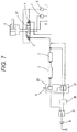
- An example of the electric operation system including the emergency operation device is illustrated in Fig. 7 .
- a power supply switching switch 22 is switched to an emergency operation side.
- An emergency operation switch 21 incorporated in the operation box 20 is switched in conjunction with an operation of the operation lever 9 and when a side of the electromagnetic proportional valve 4 is energized, a pilot pressure is supplied to the control valve 27, and the actuator 5 is driven.
- Patent Literature 1 JP 2000-344466 A
- an electromagnetic proportional valve with an emergency manual operation function for a case where the electromagnetic proportional valve does not work by electricity by the electromagnetic proportional valve being disconnected or the electromagnetic proportional valve itself being stuck due to contamination (mixing of impurities).
- the electromagnetic proportional valve with the emergency manual operation function since the electromagnetic proportional valve is manually fully opened during the emergency operation, similarly, there is also a problem that the actuator is suddenly operated and shock is generated during the emergency operation.
- An object of the present invention is to provide a hydraulic system and an emergency operation method which can slowly drive an actuator during an emergency operation and are excellent in safety.
- a hydraulic system according to the present invention includes:
- An emergency operation method is an emergency operation method of a hydraulic system, wherein the hydraulic system includes:
- a hydraulic system and an emergency operation method are provided which can slowly drive an actuator during an emergency operation and are excellent in safety.
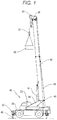
- Fig. 1 is a view illustrating a state of a mobile crane 40 suitable as a working machine on which a hydraulic system 60 (see Fig. 2 ) according to the present invention is mounted during a crane operation.
- a hydraulic system 60 see Fig. 2
- jack cylinders 43 of outriggers 42 provided at the front and rear of a lower frame 41 extend, and the mobile crane 40 is in a crane working posture in which the entire mobile crane 40 is jacked up.
- a rotation frame 44 is mounted on an upper surface of the lower frame 41 so as to be freely rotated.
- a telescopic boom 45 is connected to the rotation frame 44 by a pin 46 so as to be freely raised and lowered.
- the telescopic boom 45 is driven to be telescopic by a telescopic cylinder (not illustrated) disposed therein.
- the telescopic boom 45 is driven to be raised and lowered by a raising and lowering cylinder 47 interposed between the rotation frame 44 and the telescopic boom 45.
- a wire rope 48 is unwounded from a winch (not illustrated) disposed in the rotation frame 44 and led to a telescopic boom tip 49 along the rear surface of the telescopic boom 45. Further, the wire rope 48 is wounded around a sheave 50 of the telescopic boom tip 49, and a hook 51 is suspended at a tip of the wire rope 48. A suspended load 52 is suspended from the hook 51.
- Fig. 2 is a diagram illustrating an example of a hydraulic system mounted on the mobile crane 40.
- Fig. 2 illustrates a control system of an electric operation system in a case where an electric circuit is not broken down, that is, during a normal operation.
- the hydraulic system 60 includes a main circuit 60A which supplies a working pressure to an actuator 72 and a pilot circuit 60B which supplies a pilot pressure to a control valve 70 of the main circuit 60A.
- the main circuit 60A includes a hydraulic pump 71, the control valve 70, a pump oil passage 74, a tank oil passage 75, an operating oil tank 76, a relief valve 77, an engine 80, and an accelerator 81.
- the pilot circuit 60B has an operation lever 61, a controller 62, an electromagnetic proportional valve 63, a pilot pressure switching unit 64, a pilot pressure source 65, a pilot oil passage 69, and an emergency operation circuit 84 (see Fig. 3 ).
- the operation lever 61 converts an operation direction and an operation amount into an operation signal (electric signal) and outputs the operation signal to the controller 62.
- the controller 62 receives an operation signal from the operation lever 61 and outputs a drive signal (electric signal) to the corresponding electromagnetic proportional valve 63.
- the electromagnetic proportional valve 63 receives the drive signal from the controller 62, generates a pilot pressure proportional to the drive signal, and supplies the pilot pressure to the control valve 70. It is preferable that the electromagnetic proportional valve 63 has a detent type emergency manual operation function. Thus, even in a case where the electromagnetic proportional valve 63 itself breaks down, it is possible to respond safely.
- the control valve 70 is a pilot-type directional control valve whose drive direction is switched by a pilot pressure from the electromagnetic proportional valve 63 and which controls an operating oil pressure from the hydraulic pump 71 and supplies the operating oil pressure to the actuator 72.
- the actuator 72 is, for example, a hydraulic motor for rotation.
- the actuator 72 is not limited to a hydraulic motor but may be a hydraulic cylinder.
- the control valve 70 includes a bleed-off passage 73 whose opening area (bleed-off passage area) decreases as a stroke (switching stroke) of the spool based on a pilot pressure from the electromagnetic proportional valve 63 increases.
- the pump oil passage 74 connects the hydraulic pump 71 and the control valve 70.
- the tank oil passage 75 connects the control valve 70 and the operating oil tank 76.
- the relief valve 77 is interposed between the pump oil passage 74 and the tank oil passage 75 and operates when an oil pressure exceeds the set pressure to prevent an abnormal rise in pressure.
- the hydraulic pump 71 is, for example, a fixed displacement type hydraulic pump and is driven by the power of the engine 80 of the mobile crane 40.
- the rotational speed of the engine 80 is controlled by the operation of the accelerator 81.
- the pilot pressure switching unit 64 includes a first electromagnetic switching valve 66, a second electromagnetic switching valve 67, and a decompression valve 68.
- the pilot oil passage 69 connects the pilot pressure switching unit 64 and the electromagnetic proportional valves 63 and 63 to each other.
- the pilot pressure switching unit 64 is switched by a drive signal from the controller 62 and supplies the electromagnetic proportional valve supply pressure of the pilot pressure source 65 to the pilot oil passage 69 as it is or under reduced pressure.
- the first electromagnetic switching valve 66 is a three-port two-position switching valve, and the first electromagnetic switching valve 66 is in a blocking position which blocks the pilot pressure source 65 and the pilot oil passage 69 when not energized and is switched to a communication position which communicates the pilot pressure source 65 and the pilot oil passage 69 with each other when energized.
- the second electromagnetic switching valve 67 is a two-port two-position switching valve, and the second electromagnetic switching valve 67 is in the blocking position when not energized and is switched to the communication position which bypasses the decompression valve 68 and communicates when energized.
- the set pressure of the decompression valve 68 will be described in detail by an emergency operation to be described later.
- Both the first electromagnetic switching valve 66 and the second electromagnetic switching valve 67 are switched to the communication position and the electromagnetic proportional valve supply pressure from the pilot pressure source 65 passes through the first electromagnetic switching valve 66 and the second electromagnetic switching valve 67 and is supplied to the pilot oil passage 69 without being decompressed. Then, the electromagnetic proportional valve supply pressure (first pressure) that is not decompressed is supplied to the electromagnetic proportional valve 63 via the pilot oil passage 69.
- the controller 62 outputs a drive signal corresponding to an operation amount to the electromagnetic proportional valve 63 corresponding to the operation direction of the operation lever 61.
- the electromagnetic proportional valve 63 Upon receiving the drive signal, the electromagnetic proportional valve 63 generates the pilot pressure proportional to the drive signal and supplies a pilot pressure to the control valve 70.
- the drive direction and the stroke of the spool (valve body) of the control valve 70 are controlled according to the operation direction and the operation amount of the operation lever 61.
- the operating oil discharged from the hydraulic pump 71 is supplied to the control valve 70 via the pump oil passage 74, and a portion of the operating oil flows to the bleed-off passage 73 and returns to the operating oil tank 76 via the tank oil passage 75.
- the remaining operating oil flows to the actuator oil passage 82 (or 83) in the switched direction and drives the actuator 72 (rotation motor).
- the operating oil that drives the actuator 72 returns to the control valve 70 via the opposite actuator oil passage 83 (or 82), and returns to the operating oil tank 76 via the tank oil passage 75.
- the operating oil discharge amount by the hydraulic pump 71 increases and decreases.
- the flow rate of the operating oil flowing from the control valve 70 to the actuator 72 also increases and decreases so that the operating speed of the actuator 72 can increase and decrease.
- the engine 80 is in the idling state, and the operating oil discharge amount from the hydraulic pump 71 is the minimum discharge amount.
- the direction and the speed of the operation of the actuator 72 can be controlled by switching the drive direction of the control valve 70 by the operation lever 61 and operating the accelerator 81.
- Fig. 3 is a diagram illustrating a control system of the electric operation system in a case where the electric circuit breaks down, that is, during the emergency operation.
- the electric circuit breaks down, a case where a portion (potentiometer or the like corresponds) that converts the operation amount of the operation lever 61 into an operating electric signal breaks down, or a case where the controller 62 breaks down is considered.
- the emergency operation circuit 84 receives only the electric signal indicating the operation direction among the operation signals output from the operation lever 61 and outputs the drive signal to the corresponding electromagnetic proportional valve 63R or 63L.
- Other configurations of the hydraulic system 60 are the same as those in the normal state described with reference to Fig. 2 , so that the description thereof is omitted.
- an emergency operation is performed by an emergency operation device (see Fig. 7 ).
- the electromagnetic proportional valve is controlled so as to be fully opened, so that the actuator 72 is suddenly operated.
- the actuator 72 is a rotation motor, the rotation is performed suddenly.
- the hydraulic system 60 of the present embodiment is remarkably safe since the emergency operation is performed as follows.
- the emergency operation circuit 84 energizes the first electromagnetic switching valve 66 of the pilot pressure switching unit 64.
- the second electromagnetic switching valve 67 is in a de-energized state and is maintained at the blocking position.
- the electromagnetic proportional valve supply pressure of the pilot pressure source 65 is decompressed by passing through the first electromagnetic switching valve 66 and the decompression valve 68 to be supplied to the pilot oil passage 69 since only the first electromagnetic switching valve 66 is switched to the communication position.
- the decompressed pilot pressure hereinafter, referred to as "decompression pilot pressure" is supplied to the control valve 70 from the pilot oil passage 69 via the electromagnetic proportional valve 63L (for left rotation) of a fully opened state.
- Fig. 4 is a graph illustrating the relationship between a bleed-off passage area A and a spool stroke S of the control valve 70.
- the bleed-off passage area A is the maximum (Amax) when the spool stroke S is zero, decreases as the spool stroke S increases, and becomes zero when the spool stroke S is the maximum (Smax).
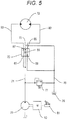
- Fig. 5 is a diagram for describing a state of the bleed-off circuit including the bleed-off passage 73 when the decompression pilot pressure is supplied to the control valve 70.
- Fig. 5 illustrates a state where the accelerator 81 is not depressed and the engine 80 is in the idling state.
- the engine 80 In the idling state, the engine 80 is rotated at the required minimum rotational speed, and the operating oil discharge amount of the fixed displacement type hydraulic pump 71 is the minimum discharge amount.
- the operating oil discharged from the hydraulic pump 71 passes through the bleed-off passage 73 of the control valve 70 via the pump oil passage 74, and then returns to the operating oil tank 76 via the tank oil passage 75.
- an operating pressure Pm (hereinafter referred to as “actuator operating pressure Pm” or “operating pressure Pm during activation”) during activation of the actuator 72 (hereinafter referred to as “hydraulic motor 72 for rotation”) is higher than the pump pressure Pp during the idling in Fig. 5 , in this state, the hydraulic motor 72 for rotation does not rotate.
- the bleed-off passage area Ae is set such that the pump pressure Pp which is slightly lower than the operating pressure Pm at the activation of the hydraulic motor 72 for rotation is generated when the operating oil with the minimum discharge amount passes through the bleed-off passage 73.
- the decompression pilot pressure that is, the set pressure (second pressure) of the decompression valve 68 is set.
- the control valve 70 when further decompressed pilot pressure is applied to the control valve 70 including the bleed-off passage 73 as compared with a pilot pressure during the normal operation, the control valve 70 can be switched to such an extent that the pump pressure Pp generated by the operating oil passing through the bleed-off passage 73 of the control valve 70 does not exceed the actuator operating pressure Pm during the idling.
- the pump pressure Pp generated by the operating oil passing through the bleed-off passage 73 of the control valve 70 increases. Accordingly, since the pump pressure Pp (operating oil pressure) exceeding the actuator operating pressure (rotation motor activation pressure) Pm is supplied from the control valve 70 to the actuator 72, the actuator 72 can be slowly activated even in the emergency operation.
- the discharge amount of the hydraulic pump 71 can further increase, and the speed of the actuator 72 can increase.
- the speed of the actuator 72 can be lowered to slowly stop.
- the pump pressure Pp during the idling may be slightly higher than the actuator operating pressure Pm within a range where the actuator 72 does not suddenly operate.
- the hydraulic system 60 includes the hydraulic pump 71, the pilot-type control valve 70 which supplies the pump pressure Pp (operating oil pressure) from the hydraulic pump 71 to the actuator 72 of the working machine, the electromagnetic proportional valve 63 which supplies a pilot pressure to the control valve 70, the operation lever 61 which receives an operation for operating the actuator 72, the controller 62 which controls the electromagnetic proportional valve 63 based on an operation signal from the operation lever 61, and the pilot pressure switching unit 64 which can switch the electromagnetic proportional valve supply pressure supplied from the pilot pressure source 65 to the electromagnetic proportional valve 63 to a first pressure during the normal operation or a second pressure lower than the first pressure.
- Pp working oil pressure
- the control valve 70 has the bleed-off passage 73 whose opening area increases and decreases according to the stroke of the spool based on a pilot pressure, and can control the pump pressure Pp which is supplied to the actuator 72 according to the opening area.
- the second pressure is set such that the pump pressure Pp is equal to or lower than a predetermined pressure when the electromagnetic proportional valve supply pressure is switched to the second pressure in a state where the operating oil discharge amount of the hydraulic pump 71 is the minimum discharge amount.
- the pilot pressure switching unit 64 switches the electromagnetic proportional valve supply pressure from the first pressure to the second pressure during the emergency operation in which the control of the electromagnetic proportional valve 63 by the controller 62 is not possible.
- the electromagnetic proportional valve is set to the fully opened state during the emergency operation. Further, as the operating oil discharge amount from the hydraulic pump 71 increases and decreases, the pump pressure Pp increases and decreases, and the operation speed of the actuator 72 is controlled.
- the hydraulic system 60 includes the emergency operation circuit 84 which controls the electromagnetic proportional valve 63 to the fully opened state based on the operation signal from the operation lever 61 during the emergency operation.
- the set pressure (second pressure) during the decompression in the pilot pressure switching unit 64 is set based on the actuator operating pressure Pm of the actuator 72.
- the second pressure is set such that the pump pressure Pp (operating oil pressure) is equal to or lower than (may slightly exceed) the actuator operating pressure Pm in a state where the operating oil discharge amount of the hydraulic pump 71 is the minimum discharge amount.
- the predetermined pressure which is the comparison reference of the pump pressure Pp is a pressure at which the actuator 72 does not operate or slowly operates, and is the actuator operating pressure Pm or a value slightly higher than the actuator operating pressure Pm.
- the power source of the hydraulic pump 71 is the engine 80 of the mobile crane 40 (working machine).
- the second pressure is set such that the pump pressure Pp (operating oil pressure) is equal to or lower than the predetermined pressure when the electromagnetic proportional valve supply pressure is switched to the second pressure in a state where the engine 80 is in the idling state.
- the operating oil discharge amount from the hydraulic pump 71 increases and decreases by operating the accelerator 81 which increases and decreases the rotational speed of the engine 80.
- the hydraulic system 60 can slowly drive the actuator 72 during the emergency operation, the hydraulic system is extremely excellent in safety.
- Fig. 6 is a diagram illustrating another example of the control system of the electric operation system in a case where the electromagnetic proportional valve 63 breaks down.
- the electromagnetic proportional valve 63 breaks down, it is considered that the electromagnetic proportional valve 63 is disconnected, or the electromagnetic proportional valve 63 is stuck by contamination. In this case, the electromagnetic proportional valve 63 cannot be moved by electricity.
- the operator operates the emergency operation activation switch 90 in the operating room and switches the first electromagnetic switching valve 66 of the pilot pressure switching unit 64 to the communication side.
- the electromagnetic proportional valve supply pressure of the pilot pressure source 65 is decompressed to a predetermined pressure (second pressure) by passing through the first electromagnetic switching valve 66 and the decompression valve 68 and is supplied to the pilot oil passage 69.
- the decompression pilot pressure is supplied from the pilot oil passage 69 to the control valve 70 via the electromagnetic proportional valve 63L (for left rotation) in a fully opened state.
- the subsequent emergency operation is the same as the emergency operation in the control system in a case where the electric circuit breaks down illustrated in Fig. 3 .
- the discharge amount of the hydraulic pump 71 can further increase and decrease, and the speed of the actuator 72 can increase and decrease.
- the speed of the actuator 72 can be lowered to slowly stop the actuator.
- the pump pressure Pp during the idling may be slightly higher than the operating pressure Pm within a range in which the actuator 72 does not suddenly operate.
- the mobile crane 40 can be slowly activated/slowly stopped even when performing the rotation operation during the emergency in the crane working posture illustrated in Fig. 1 , there is no concern that the suspended load 52 swings largely and strikes the telescopic boom 45. Therefore, it is possible to perform the emergency operation safely.
- a drive signal may be output from the controller 62 to the electromagnetic proportional valve 63 so as to apply a pilot pressure which becomes the spool stroke Se (bleed-off passage area Ae) illustrated in Fig. 4 to the control valve 70.
- the operation signal since information corresponding to the drive amount of the operation lever 61 is not transmitted to the electromagnetic proportional valve 63, this case is also included in an example during the emergency operation where the control of the electromagnetic proportional valve 63 by the controller 62 is not possible.
- control valve 70 can be switched to such an extent that the pump pressure Pp generated by the operating oil passing through the bleed-off passage 73 of the control valve 70 does not exceed the actuator operating pressure Pm.
- the pump pressure Pp generated by the operating oil passing through the bleed-off passage 73 of the control valve 70 increases. Accordingly, the pump pressure Pp exceeding the actuator operating pressure Pm is supplied from the control valve 70 to the actuator 72, so that the actuator 72 can be slowly activated even during the emergency operation.
- the discharge amount of the hydraulic pump 71 can further increase and decrease, and the speed of the actuator 72 can increase and decrease.
- the speed of the actuator 72 can be reduced to slowly stop the actuator.
- the pump pressure Pp during the idling may be slightly higher than the operating pressure Pm within a range in which the actuator 72 does not suddenly operate.
- the hydraulic pump may be configured by a variable displacement type hydraulic pump, and the discharge amount per rotation may be changed.
Landscapes
- Engineering & Computer Science (AREA)
- Chemical & Material Sciences (AREA)
- Analytical Chemistry (AREA)
- Physics & Mathematics (AREA)
- Fluid Mechanics (AREA)
- Mechanical Engineering (AREA)
- General Engineering & Computer Science (AREA)
- Fluid-Pressure Circuits (AREA)
- Control And Safety Of Cranes (AREA)
Applications Claiming Priority (2)
| Application Number | Priority Date | Filing Date | Title |
|---|---|---|---|
| JP2016070733 | 2016-03-31 | ||
| PCT/JP2017/013645 WO2017171021A1 (ja) | 2016-03-31 | 2017-03-31 | 油圧システム及び非常操作方法 |
Publications (3)
| Publication Number | Publication Date |
|---|---|
| EP3438467A1 true EP3438467A1 (de) | 2019-02-06 |
| EP3438467A4 EP3438467A4 (de) | 2019-11-06 |
| EP3438467B1 EP3438467B1 (de) | 2021-03-03 |
Family
ID=59966003
Family Applications (1)
| Application Number | Title | Priority Date | Filing Date |
|---|---|---|---|
| EP17775552.7A Active EP3438467B1 (de) | 2016-03-31 | 2017-03-31 | Hydraulisches system und notfallbetriebsverfahren |
Country Status (5)
| Country | Link |
|---|---|
| US (1) | US10995778B2 (de) |
| EP (1) | EP3438467B1 (de) |
| JP (1) | JP6848964B2 (de) |
| CN (1) | CN108884842B (de) |
| WO (1) | WO2017171021A1 (de) |
Families Citing this family (11)
| Publication number | Priority date | Publication date | Assignee | Title |
|---|---|---|---|---|
| DK3529130T3 (da) * | 2016-10-18 | 2023-06-19 | Parker Hannifin Emea Sarl | Elektrohydraulisk styresystem med fejlskre pilotventiler |
| CN107605871B (zh) * | 2017-10-20 | 2023-11-14 | 江苏高德液压机械有限公司 | 带阶梯压缩式推料装置的箱式剪切机的液压系统 |
| CN109826998B (zh) * | 2019-03-20 | 2024-03-08 | 北京世纪合兴起重科技有限公司 | 螺杆启闭机液控应急操作设备 |
| JP2021038787A (ja) * | 2019-09-03 | 2021-03-11 | 川崎重工業株式会社 | 建設機械の油圧システム |
| WO2021145346A1 (ja) * | 2020-01-14 | 2021-07-22 | 住友重機械工業株式会社 | ショベル、遠隔操作支援装置 |
| CN111501894B (zh) * | 2020-05-19 | 2024-02-02 | 江苏徐工工程机械研究院有限公司 | 行驶稳定系统、挖掘装载机及控制方法 |
| JP7523339B2 (ja) * | 2020-12-11 | 2024-07-26 | 日立建機株式会社 | 作業機械 |
| US11976675B2 (en) * | 2021-02-11 | 2024-05-07 | Xtreme Manufacturing, Llc | Systems and methods for bleed down and retraction of a construction machine boom |
| CN114893459B (zh) * | 2022-04-25 | 2024-05-24 | 阳春新钢铁有限责任公司 | 一种lf精炼炉用电极升降液压转换备用系统 |
| CN114810696B (zh) * | 2022-04-28 | 2025-04-22 | 柳州柳工挖掘机有限公司 | 液压系统、控制方法和轮式挖掘机 |
| CN119288936B (zh) * | 2024-11-11 | 2025-10-31 | 湖南中联重科履带起重机有限公司 | 工程机械的液控操作系统、液控操作方法及工程机械 |
Family Cites Families (15)
| Publication number | Priority date | Publication date | Assignee | Title |
|---|---|---|---|---|
| JP3417833B2 (ja) * | 1998-03-30 | 2003-06-16 | コベルコ建機株式会社 | 油圧制御装置 |
| JP3750841B2 (ja) * | 1998-11-12 | 2006-03-01 | 新キャタピラー三菱株式会社 | 作業機械における油圧制御装置 |
| JP2000344466A (ja) | 1999-06-07 | 2000-12-12 | Tadano Ltd | 作業車の操作装置 |
| DE10342789B4 (de) * | 2003-09-15 | 2012-05-24 | Linde Material Handling Gmbh | Hydrostatisches Antriebssystem mit einer Sicherheitseinrichtung |
| KR100641393B1 (ko) * | 2004-12-07 | 2006-11-01 | 볼보 컨스트럭션 이키프먼트 홀딩 스웨덴 에이비 | 유압제어회로 및 유압제어방법 |
| JP4896774B2 (ja) * | 2007-02-28 | 2012-03-14 | 日立建機株式会社 | 油圧作業機械の安全装置 |
| US8495870B2 (en) * | 2009-03-19 | 2013-07-30 | Kubota Corporation | Work machine |
| US9187297B2 (en) * | 2011-05-13 | 2015-11-17 | Kabushiki Kaisha Kobe Seiko Sho | Hydraulic driving apparatus for working machine |
| JP5707287B2 (ja) * | 2011-09-26 | 2015-04-30 | 株式会社神戸製鋼所 | 作業機械の油圧駆動装置 |
| AU2013238399B2 (en) * | 2012-03-26 | 2016-02-18 | Hitachi Construction Machinery Co., Ltd. | Transport vehicle |
| WO2013169996A1 (en) * | 2012-05-10 | 2013-11-14 | Eaton Corporation | Load energy assist and horsepower management system |
| JP5969323B2 (ja) * | 2012-08-29 | 2016-08-17 | 日本自動機工株式会社 | ゲート上昇・降下機構 |
| WO2014137250A1 (en) * | 2013-03-06 | 2014-09-12 | Volvo Construction Equipment Ab | Pilot pressure control system |
| CN105339562A (zh) * | 2013-06-26 | 2016-02-17 | 沃尔沃建造设备有限公司 | 用于控制工程机械的控制阀的设备及其控制方法以及用于控制液压泵的排放流量的方法 |
| WO2015102120A1 (ko) * | 2013-12-30 | 2015-07-09 | 볼보 컨스트럭션 이큅먼트 에이비 | 유압제어장치 및 이를 구비한 건설기계 |
-
2017
- 2017-03-31 US US16/089,718 patent/US10995778B2/en active Active
- 2017-03-31 EP EP17775552.7A patent/EP3438467B1/de active Active
- 2017-03-31 CN CN201780020904.2A patent/CN108884842B/zh active Active
- 2017-03-31 WO PCT/JP2017/013645 patent/WO2017171021A1/ja not_active Ceased
- 2017-03-31 JP JP2018509665A patent/JP6848964B2/ja active Active
Also Published As
| Publication number | Publication date |
|---|---|
| US10995778B2 (en) | 2021-05-04 |
| JP6848964B2 (ja) | 2021-03-24 |
| CN108884842A (zh) | 2018-11-23 |
| EP3438467B1 (de) | 2021-03-03 |
| CN108884842B (zh) | 2021-03-02 |
| US20200309166A1 (en) | 2020-10-01 |
| EP3438467A4 (de) | 2019-11-06 |
| JPWO2017171021A1 (ja) | 2019-02-07 |
| WO2017171021A1 (ja) | 2017-10-05 |
Similar Documents
| Publication | Publication Date | Title |
|---|---|---|
| EP3438467B1 (de) | Hydraulisches system und notfallbetriebsverfahren | |
| EP3434913B1 (de) | Hydrauliksystem | |
| CN102153027B (zh) | 一种液压绞车无级调节恒张力装置 | |
| EP2696081B1 (de) | Hydraulischer maschinenantrieb | |
| US20120285152A1 (en) | Hydraulic driving apparatus for working machine | |
| CN107882792B (zh) | 电磁卸荷阀及装载机双泵合流液压系统 | |
| CN102917972B (zh) | 重型设备作业机的上升速度控制装置 | |
| CN114212719B (zh) | 一种保护绞车的液压系统的控制方法 | |
| EP3196367A1 (de) | Hydraulikschaltung für eine baumaschine | |
| JP3768989B2 (ja) | 重装備オプション装置用油圧回路 | |
| US11613451B2 (en) | Speed control system for crane and winch applications | |
| JPH09317652A (ja) | ローダのエンジン/ポンプ制御装置 | |
| CN216691642U (zh) | 一种绞车控制的液压系统 | |
| KR101688233B1 (ko) | 중장비의 시동 꺼짐 방지 시스템 | |
| CN203702753U (zh) | 工程机械及液压系统 | |
| CN114857101B (zh) | 一种调速液压绞车智能保护系统 | |
| KR20040004047A (ko) | 건설기계의 액추에이터구동용 유압파일럿회로 | |
| KR102847015B1 (ko) | 제어 장치 및 건설 기계 | |
| JPH07187585A (ja) | ウインチの速度制御方法、および速度制御システム | |
| CN114215798A (zh) | 一种保护绞车的液压系统 | |
| JP2015086961A (ja) | 制限荷重切換機能付き昇降装置 | |
| KR200296790Y1 (ko) | 에어 윈치의 과부하 방지장치 | |
| JP2005054526A (ja) | 建設機械の旋回制御装置 | |
| US20250376993A1 (en) | Hydraulic drive device | |
| JP3939037B2 (ja) | 作業機の油圧駆動制御装置 |
Legal Events
| Date | Code | Title | Description |
|---|---|---|---|
| STAA | Information on the status of an ep patent application or granted ep patent |
Free format text: STATUS: THE INTERNATIONAL PUBLICATION HAS BEEN MADE |
|
| PUAI | Public reference made under article 153(3) epc to a published international application that has entered the european phase |
Free format text: ORIGINAL CODE: 0009012 |
|
| STAA | Information on the status of an ep patent application or granted ep patent |
Free format text: STATUS: REQUEST FOR EXAMINATION WAS MADE |
|
| 17P | Request for examination filed |
Effective date: 20181022 |
|
| AK | Designated contracting states |
Kind code of ref document: A1 Designated state(s): AL AT BE BG CH CY CZ DE DK EE ES FI FR GB GR HR HU IE IS IT LI LT LU LV MC MK MT NL NO PL PT RO RS SE SI SK SM TR |
|
| AX | Request for extension of the european patent |
Extension state: BA ME |
|
| DAV | Request for validation of the european patent (deleted) | ||
| DAX | Request for extension of the european patent (deleted) | ||
| A4 | Supplementary search report drawn up and despatched |
Effective date: 20191007 |
|
| RIC1 | Information provided on ipc code assigned before grant |
Ipc: F15B 11/00 20060101AFI20190930BHEP Ipc: F15B 11/08 20060101ALI20190930BHEP Ipc: B66C 13/22 20060101ALI20190930BHEP Ipc: F15B 20/00 20060101ALI20190930BHEP |
|
| GRAP | Despatch of communication of intention to grant a patent |
Free format text: ORIGINAL CODE: EPIDOSNIGR1 |
|
| STAA | Information on the status of an ep patent application or granted ep patent |
Free format text: STATUS: GRANT OF PATENT IS INTENDED |
|
| INTG | Intention to grant announced |
Effective date: 20200925 |
|
| GRAS | Grant fee paid |
Free format text: ORIGINAL CODE: EPIDOSNIGR3 |
|
| GRAA | (expected) grant |
Free format text: ORIGINAL CODE: 0009210 |
|
| STAA | Information on the status of an ep patent application or granted ep patent |
Free format text: STATUS: THE PATENT HAS BEEN GRANTED |
|
| AK | Designated contracting states |
Kind code of ref document: B1 Designated state(s): AL AT BE BG CH CY CZ DE DK EE ES FI FR GB GR HR HU IE IS IT LI LT LU LV MC MK MT NL NO PL PT RO RS SE SI SK SM TR |
|
| REG | Reference to a national code |
Ref country code: GB Ref legal event code: FG4D |
|
| REG | Reference to a national code |
Ref country code: AT Ref legal event code: REF Ref document number: 1367511 Country of ref document: AT Kind code of ref document: T Effective date: 20210315 Ref country code: CH Ref legal event code: EP |
|
| REG | Reference to a national code |
Ref country code: DE Ref legal event code: R096 Ref document number: 602017033893 Country of ref document: DE |
|
| REG | Reference to a national code |
Ref country code: IE Ref legal event code: FG4D |
|
| REG | Reference to a national code |
Ref country code: LT Ref legal event code: MG9D |
|
| PG25 | Lapsed in a contracting state [announced via postgrant information from national office to epo] |
Ref country code: NO Free format text: LAPSE BECAUSE OF FAILURE TO SUBMIT A TRANSLATION OF THE DESCRIPTION OR TO PAY THE FEE WITHIN THE PRESCRIBED TIME-LIMIT Effective date: 20210603 Ref country code: FI Free format text: LAPSE BECAUSE OF FAILURE TO SUBMIT A TRANSLATION OF THE DESCRIPTION OR TO PAY THE FEE WITHIN THE PRESCRIBED TIME-LIMIT Effective date: 20210303 Ref country code: GR Free format text: LAPSE BECAUSE OF FAILURE TO SUBMIT A TRANSLATION OF THE DESCRIPTION OR TO PAY THE FEE WITHIN THE PRESCRIBED TIME-LIMIT Effective date: 20210604 Ref country code: HR Free format text: LAPSE BECAUSE OF FAILURE TO SUBMIT A TRANSLATION OF THE DESCRIPTION OR TO PAY THE FEE WITHIN THE PRESCRIBED TIME-LIMIT Effective date: 20210303 Ref country code: LT Free format text: LAPSE BECAUSE OF FAILURE TO SUBMIT A TRANSLATION OF THE DESCRIPTION OR TO PAY THE FEE WITHIN THE PRESCRIBED TIME-LIMIT Effective date: 20210303 Ref country code: BG Free format text: LAPSE BECAUSE OF FAILURE TO SUBMIT A TRANSLATION OF THE DESCRIPTION OR TO PAY THE FEE WITHIN THE PRESCRIBED TIME-LIMIT Effective date: 20210603 |
|
| REG | Reference to a national code |
Ref country code: NL Ref legal event code: MP Effective date: 20210303 |
|
| REG | Reference to a national code |
Ref country code: AT Ref legal event code: MK05 Ref document number: 1367511 Country of ref document: AT Kind code of ref document: T Effective date: 20210303 |
|
| PG25 | Lapsed in a contracting state [announced via postgrant information from national office to epo] |
Ref country code: SE Free format text: LAPSE BECAUSE OF FAILURE TO SUBMIT A TRANSLATION OF THE DESCRIPTION OR TO PAY THE FEE WITHIN THE PRESCRIBED TIME-LIMIT Effective date: 20210303 Ref country code: LV Free format text: LAPSE BECAUSE OF FAILURE TO SUBMIT A TRANSLATION OF THE DESCRIPTION OR TO PAY THE FEE WITHIN THE PRESCRIBED TIME-LIMIT Effective date: 20210303 Ref country code: PL Free format text: LAPSE BECAUSE OF FAILURE TO SUBMIT A TRANSLATION OF THE DESCRIPTION OR TO PAY THE FEE WITHIN THE PRESCRIBED TIME-LIMIT Effective date: 20210303 Ref country code: RS Free format text: LAPSE BECAUSE OF FAILURE TO SUBMIT A TRANSLATION OF THE DESCRIPTION OR TO PAY THE FEE WITHIN THE PRESCRIBED TIME-LIMIT Effective date: 20210303 |
|
| PG25 | Lapsed in a contracting state [announced via postgrant information from national office to epo] |
Ref country code: NL Free format text: LAPSE BECAUSE OF FAILURE TO SUBMIT A TRANSLATION OF THE DESCRIPTION OR TO PAY THE FEE WITHIN THE PRESCRIBED TIME-LIMIT Effective date: 20210303 |
|
| PG25 | Lapsed in a contracting state [announced via postgrant information from national office to epo] |
Ref country code: EE Free format text: LAPSE BECAUSE OF FAILURE TO SUBMIT A TRANSLATION OF THE DESCRIPTION OR TO PAY THE FEE WITHIN THE PRESCRIBED TIME-LIMIT Effective date: 20210303 Ref country code: CZ Free format text: LAPSE BECAUSE OF FAILURE TO SUBMIT A TRANSLATION OF THE DESCRIPTION OR TO PAY THE FEE WITHIN THE PRESCRIBED TIME-LIMIT Effective date: 20210303 Ref country code: AT Free format text: LAPSE BECAUSE OF FAILURE TO SUBMIT A TRANSLATION OF THE DESCRIPTION OR TO PAY THE FEE WITHIN THE PRESCRIBED TIME-LIMIT Effective date: 20210303 Ref country code: SM Free format text: LAPSE BECAUSE OF FAILURE TO SUBMIT A TRANSLATION OF THE DESCRIPTION OR TO PAY THE FEE WITHIN THE PRESCRIBED TIME-LIMIT Effective date: 20210303 |
|
| REG | Reference to a national code |
Ref country code: CH Ref legal event code: PL |
|
| PG25 | Lapsed in a contracting state [announced via postgrant information from national office to epo] |
Ref country code: IS Free format text: LAPSE BECAUSE OF FAILURE TO SUBMIT A TRANSLATION OF THE DESCRIPTION OR TO PAY THE FEE WITHIN THE PRESCRIBED TIME-LIMIT Effective date: 20210703 Ref country code: PT Free format text: LAPSE BECAUSE OF FAILURE TO SUBMIT A TRANSLATION OF THE DESCRIPTION OR TO PAY THE FEE WITHIN THE PRESCRIBED TIME-LIMIT Effective date: 20210705 Ref country code: RO Free format text: LAPSE BECAUSE OF FAILURE TO SUBMIT A TRANSLATION OF THE DESCRIPTION OR TO PAY THE FEE WITHIN THE PRESCRIBED TIME-LIMIT Effective date: 20210303 Ref country code: SK Free format text: LAPSE BECAUSE OF FAILURE TO SUBMIT A TRANSLATION OF THE DESCRIPTION OR TO PAY THE FEE WITHIN THE PRESCRIBED TIME-LIMIT Effective date: 20210303 |
|
| REG | Reference to a national code |
Ref country code: DE Ref legal event code: R097 Ref document number: 602017033893 Country of ref document: DE |
|
| REG | Reference to a national code |
Ref country code: BE Ref legal event code: MM Effective date: 20210331 |
|
| PLBE | No opposition filed within time limit |
Free format text: ORIGINAL CODE: 0009261 |
|
| STAA | Information on the status of an ep patent application or granted ep patent |
Free format text: STATUS: NO OPPOSITION FILED WITHIN TIME LIMIT |
|
| PG25 | Lapsed in a contracting state [announced via postgrant information from national office to epo] |
Ref country code: CH Free format text: LAPSE BECAUSE OF NON-PAYMENT OF DUE FEES Effective date: 20210331 Ref country code: DK Free format text: LAPSE BECAUSE OF FAILURE TO SUBMIT A TRANSLATION OF THE DESCRIPTION OR TO PAY THE FEE WITHIN THE PRESCRIBED TIME-LIMIT Effective date: 20210303 Ref country code: AL Free format text: LAPSE BECAUSE OF FAILURE TO SUBMIT A TRANSLATION OF THE DESCRIPTION OR TO PAY THE FEE WITHIN THE PRESCRIBED TIME-LIMIT Effective date: 20210303 Ref country code: MC Free format text: LAPSE BECAUSE OF FAILURE TO SUBMIT A TRANSLATION OF THE DESCRIPTION OR TO PAY THE FEE WITHIN THE PRESCRIBED TIME-LIMIT Effective date: 20210303 Ref country code: LI Free format text: LAPSE BECAUSE OF NON-PAYMENT OF DUE FEES Effective date: 20210331 Ref country code: LU Free format text: LAPSE BECAUSE OF NON-PAYMENT OF DUE FEES Effective date: 20210331 Ref country code: ES Free format text: LAPSE BECAUSE OF FAILURE TO SUBMIT A TRANSLATION OF THE DESCRIPTION OR TO PAY THE FEE WITHIN THE PRESCRIBED TIME-LIMIT Effective date: 20210303 Ref country code: FR Free format text: LAPSE BECAUSE OF NON-PAYMENT OF DUE FEES Effective date: 20210503 Ref country code: IE Free format text: LAPSE BECAUSE OF NON-PAYMENT OF DUE FEES Effective date: 20210331 |
|
| 26N | No opposition filed |
Effective date: 20211206 |
|
| GBPC | Gb: european patent ceased through non-payment of renewal fee |
Effective date: 20210603 |
|
| PG25 | Lapsed in a contracting state [announced via postgrant information from national office to epo] |
Ref country code: SI Free format text: LAPSE BECAUSE OF FAILURE TO SUBMIT A TRANSLATION OF THE DESCRIPTION OR TO PAY THE FEE WITHIN THE PRESCRIBED TIME-LIMIT Effective date: 20210303 |
|
| PG25 | Lapsed in a contracting state [announced via postgrant information from national office to epo] |
Ref country code: IT Free format text: LAPSE BECAUSE OF FAILURE TO SUBMIT A TRANSLATION OF THE DESCRIPTION OR TO PAY THE FEE WITHIN THE PRESCRIBED TIME-LIMIT Effective date: 20210303 Ref country code: GB Free format text: LAPSE BECAUSE OF NON-PAYMENT OF DUE FEES Effective date: 20210603 |
|
| PG25 | Lapsed in a contracting state [announced via postgrant information from national office to epo] |
Ref country code: IS Free format text: LAPSE BECAUSE OF FAILURE TO SUBMIT A TRANSLATION OF THE DESCRIPTION OR TO PAY THE FEE WITHIN THE PRESCRIBED TIME-LIMIT Effective date: 20210703 |
|
| PG25 | Lapsed in a contracting state [announced via postgrant information from national office to epo] |
Ref country code: BE Free format text: LAPSE BECAUSE OF NON-PAYMENT OF DUE FEES Effective date: 20210331 |
|
| PG25 | Lapsed in a contracting state [announced via postgrant information from national office to epo] |
Ref country code: CY Free format text: LAPSE BECAUSE OF FAILURE TO SUBMIT A TRANSLATION OF THE DESCRIPTION OR TO PAY THE FEE WITHIN THE PRESCRIBED TIME-LIMIT Effective date: 20210303 |
|
| PG25 | Lapsed in a contracting state [announced via postgrant information from national office to epo] |
Ref country code: HU Free format text: LAPSE BECAUSE OF FAILURE TO SUBMIT A TRANSLATION OF THE DESCRIPTION OR TO PAY THE FEE WITHIN THE PRESCRIBED TIME-LIMIT; INVALID AB INITIO Effective date: 20170331 |
|
| PG25 | Lapsed in a contracting state [announced via postgrant information from national office to epo] |
Ref country code: MK Free format text: LAPSE BECAUSE OF FAILURE TO SUBMIT A TRANSLATION OF THE DESCRIPTION OR TO PAY THE FEE WITHIN THE PRESCRIBED TIME-LIMIT Effective date: 20210303 |
|
| PG25 | Lapsed in a contracting state [announced via postgrant information from national office to epo] |
Ref country code: MT Free format text: LAPSE BECAUSE OF FAILURE TO SUBMIT A TRANSLATION OF THE DESCRIPTION OR TO PAY THE FEE WITHIN THE PRESCRIBED TIME-LIMIT Effective date: 20210303 |
|
| PG25 | Lapsed in a contracting state [announced via postgrant information from national office to epo] |
Ref country code: TR Free format text: LAPSE BECAUSE OF FAILURE TO SUBMIT A TRANSLATION OF THE DESCRIPTION OR TO PAY THE FEE WITHIN THE PRESCRIBED TIME-LIMIT Effective date: 20210303 |
|
| PGFP | Annual fee paid to national office [announced via postgrant information from national office to epo] |
Ref country code: DE Payment date: 20260320 Year of fee payment: 10 |