EP3439909B1 - Fahrzeugsitz mit mindestens einem pneumatischen kissen - Google Patents
Fahrzeugsitz mit mindestens einem pneumatischen kissen Download PDFInfo
- Publication number
- EP3439909B1 EP3439909B1 EP16808668.4A EP16808668A EP3439909B1 EP 3439909 B1 EP3439909 B1 EP 3439909B1 EP 16808668 A EP16808668 A EP 16808668A EP 3439909 B1 EP3439909 B1 EP 3439909B1
- Authority
- EP
- European Patent Office
- Prior art keywords
- pneumatic
- vehicle seat
- pneumatic cushion
- seat
- backrest
- Prior art date
- Legal status (The legal status is an assumption and is not a legal conclusion. Google has not performed a legal analysis and makes no representation as to the accuracy of the status listed.)
- Active
Links
Images

Classifications
-
- B—PERFORMING OPERATIONS; TRANSPORTING
- B64—AIRCRAFT; AVIATION; COSMONAUTICS
- B64D—EQUIPMENT FOR FITTING IN OR TO AIRCRAFT; FLIGHT SUITS; PARACHUTES; ARRANGEMENT OR MOUNTING OF POWER PLANTS OR PROPULSION TRANSMISSIONS IN AIRCRAFT
- B64D11/00—Passenger or crew accommodation; Flight-deck installations not otherwise provided for
- B64D11/06—Arrangements of seats, or adaptations or details specially adapted for aircraft seats
- B64D11/0639—Arrangements of seats, or adaptations or details specially adapted for aircraft seats with features for adjustment or converting of seats
- B64D11/064—Adjustable inclination or position of seats
-
- B—PERFORMING OPERATIONS; TRANSPORTING
- B60—VEHICLES IN GENERAL
- B60N—SEATS SPECIALLY ADAPTED FOR VEHICLES; VEHICLE PASSENGER ACCOMMODATION NOT OTHERWISE PROVIDED FOR
- B60N2/00—Seats specially adapted for vehicles; Arrangement or mounting of seats in vehicles
- B60N2/02—Seats specially adapted for vehicles; Arrangement or mounting of seats in vehicles the seat or part thereof being movable, e.g. adjustable
- B60N2/0224—Non-manual adjustments, e.g. with electrical operation
- B60N2/02246—Electric motors therefor
-
- B—PERFORMING OPERATIONS; TRANSPORTING
- B60—VEHICLES IN GENERAL
- B60N—SEATS SPECIALLY ADAPTED FOR VEHICLES; VEHICLE PASSENGER ACCOMMODATION NOT OTHERWISE PROVIDED FOR
- B60N2/00—Seats specially adapted for vehicles; Arrangement or mounting of seats in vehicles
- B60N2/02—Seats specially adapted for vehicles; Arrangement or mounting of seats in vehicles the seat or part thereof being movable, e.g. adjustable
- B60N2/20—Seats specially adapted for vehicles; Arrangement or mounting of seats in vehicles the seat or part thereof being movable, e.g. adjustable the back-rest being tiltable, e.g. to permit easy access
-
- B—PERFORMING OPERATIONS; TRANSPORTING
- B60—VEHICLES IN GENERAL
- B60N—SEATS SPECIALLY ADAPTED FOR VEHICLES; VEHICLE PASSENGER ACCOMMODATION NOT OTHERWISE PROVIDED FOR
- B60N2/00—Seats specially adapted for vehicles; Arrangement or mounting of seats in vehicles
- B60N2/24—Seats specially adapted for vehicles; Arrangement or mounting of seats in vehicles for particular purposes or particular vehicles
- B60N2/32—Seats specially adapted for vehicles; Arrangement or mounting of seats in vehicles for particular purposes or particular vehicles convertible for other use
- B60N2/34—Seats specially adapted for vehicles; Arrangement or mounting of seats in vehicles for particular purposes or particular vehicles convertible for other use into a bed
-
- B—PERFORMING OPERATIONS; TRANSPORTING
- B60—VEHICLES IN GENERAL
- B60N—SEATS SPECIALLY ADAPTED FOR VEHICLES; VEHICLE PASSENGER ACCOMMODATION NOT OTHERWISE PROVIDED FOR
- B60N2/00—Seats specially adapted for vehicles; Arrangement or mounting of seats in vehicles
- B60N2/90—Details or parts not otherwise provided for
- B60N2/914—Hydro-pneumatic adjustments of the shape
-
- B—PERFORMING OPERATIONS; TRANSPORTING
- B64—AIRCRAFT; AVIATION; COSMONAUTICS
- B64D—EQUIPMENT FOR FITTING IN OR TO AIRCRAFT; FLIGHT SUITS; PARACHUTES; ARRANGEMENT OR MOUNTING OF POWER PLANTS OR PROPULSION TRANSMISSIONS IN AIRCRAFT
- B64D11/00—Passenger or crew accommodation; Flight-deck installations not otherwise provided for
- B64D11/06—Arrangements of seats, or adaptations or details specially adapted for aircraft seats
- B64D11/0639—Arrangements of seats, or adaptations or details specially adapted for aircraft seats with features for adjustment or converting of seats
-
- B—PERFORMING OPERATIONS; TRANSPORTING
- B64—AIRCRAFT; AVIATION; COSMONAUTICS
- B64D—EQUIPMENT FOR FITTING IN OR TO AIRCRAFT; FLIGHT SUITS; PARACHUTES; ARRANGEMENT OR MOUNTING OF POWER PLANTS OR PROPULSION TRANSMISSIONS IN AIRCRAFT
- B64D11/00—Passenger or crew accommodation; Flight-deck installations not otherwise provided for
- B64D11/06—Arrangements of seats, or adaptations or details specially adapted for aircraft seats
- B64D11/0639—Arrangements of seats, or adaptations or details specially adapted for aircraft seats with features for adjustment or converting of seats
- B64D11/0641—Seats convertible into beds
-
- B—PERFORMING OPERATIONS; TRANSPORTING
- B64—AIRCRAFT; AVIATION; COSMONAUTICS
- B64D—EQUIPMENT FOR FITTING IN OR TO AIRCRAFT; FLIGHT SUITS; PARACHUTES; ARRANGEMENT OR MOUNTING OF POWER PLANTS OR PROPULSION TRANSMISSIONS IN AIRCRAFT
- B64D11/00—Passenger or crew accommodation; Flight-deck installations not otherwise provided for
- B64D11/06—Arrangements of seats, or adaptations or details specially adapted for aircraft seats
- B64D11/0639—Arrangements of seats, or adaptations or details specially adapted for aircraft seats with features for adjustment or converting of seats
- B64D11/0643—Adjustable foot or leg rests
-
- B—PERFORMING OPERATIONS; TRANSPORTING
- B64—AIRCRAFT; AVIATION; COSMONAUTICS
- B64D—EQUIPMENT FOR FITTING IN OR TO AIRCRAFT; FLIGHT SUITS; PARACHUTES; ARRANGEMENT OR MOUNTING OF POWER PLANTS OR PROPULSION TRANSMISSIONS IN AIRCRAFT
- B64D11/00—Passenger or crew accommodation; Flight-deck installations not otherwise provided for
- B64D11/06—Arrangements of seats, or adaptations or details specially adapted for aircraft seats
- B64D11/0647—Seats characterised by special upholstery or cushioning features
-
- B—PERFORMING OPERATIONS; TRANSPORTING
- B60—VEHICLES IN GENERAL
- B60N—SEATS SPECIALLY ADAPTED FOR VEHICLES; VEHICLE PASSENGER ACCOMMODATION NOT OTHERWISE PROVIDED FOR
- B60N2/00—Seats specially adapted for vehicles; Arrangement or mounting of seats in vehicles
- B60N2/24—Seats specially adapted for vehicles; Arrangement or mounting of seats in vehicles for particular purposes or particular vehicles
- B60N2/32—Seats specially adapted for vehicles; Arrangement or mounting of seats in vehicles for particular purposes or particular vehicles convertible for other use
- B60N2/36—Seats specially adapted for vehicles; Arrangement or mounting of seats in vehicles for particular purposes or particular vehicles convertible for other use into a loading platform
- B60N2002/363—Seats specially adapted for vehicles; Arrangement or mounting of seats in vehicles for particular purposes or particular vehicles convertible for other use into a loading platform characterised by provisions for enhancing the cargo floor surface, e.g. elements closing gaps or enlarging the back-rest surface
-
- Y—GENERAL TAGGING OF NEW TECHNOLOGICAL DEVELOPMENTS; GENERAL TAGGING OF CROSS-SECTIONAL TECHNOLOGIES SPANNING OVER SEVERAL SECTIONS OF THE IPC; TECHNICAL SUBJECTS COVERED BY FORMER USPC CROSS-REFERENCE ART COLLECTIONS [XRACs] AND DIGESTS
- Y02—TECHNOLOGIES OR APPLICATIONS FOR MITIGATION OR ADAPTATION AGAINST CLIMATE CHANGE
- Y02T—CLIMATE CHANGE MITIGATION TECHNOLOGIES RELATED TO TRANSPORTATION
- Y02T50/00—Aeronautics or air transport
- Y02T50/40—Weight reduction
Definitions
- the invention relates to a vehicle seat with at least one pneumatic cushion, which is inflated by a pneumatic unit when a backrest element changes to a lying position and is emptied when the backrest element changes to a sitting position.
- pneumatic cushions in vehicle seats, in particular in the area of aircraft seats, is known.
- a major advantage of pneumatic cushions is the reduced weight and the possibility of being able to adjust the hardness of the pneumatic cushions depending on external factors or the personal taste of a passenger sitting on the vehicle seat.
- the DE 10 2010 020 642 (Dornier Technologie GmbH & Co KG) an aircraft seat with an inclination sensor for the backrest, the pressure being regulated as a function of the measured inclination angle of the backrest in at least one inflatable air cushion.
- the inclination sensor is preferably designed as an absolute inclination sensor, which is integrated in a pneumatic unit of the seat.
- the pressure of the at least one inflatable air cushion can be regulated as a function of the absolute backrest angle in relation to the horizontal and not, as in known systems, on the basis of the relative angle between the backrest and seat surface.
- the WO 2015/073363 discloses premium seats for aircraft, which can be transferred from a sitting position to a lying position.
- the seats have a plurality of inflatable chambers, which cushion a sleeping passenger when the aircraft is moving.
- the chambers are selectively inflated and deflated as the seats are transferred between positions.
- a generic vehicle seat is in the EP2944509 disclosed.
- the object of the invention is to provide a vehicle seat belonging to the technical field mentioned at the outset which offers greater lying comfort in a lying position.
- the vehicle seat comprises a seat surface and at least one backrest element which can be pivoted about an axis relative to the seat surface.
- the at least one backrest element is from a sitting position in which the backrest element is essentially at an obtuse or obtuse angle relative to the seat surface, in a lying position in which the seat surface and the backrest element form an essentially flat surface, and can be moved back.
- the aircraft seat has at least one pneumatic cushion and a pneumatic unit which is designed in such a way that it substantially completely inflates the at least one pneumatic cushion when the at least one backrest element is moved into the lying position, and essentially completely empties the pneumatic cushion when the at least one backrest element is moved into the sitting position.
- the at least one pneumatic cushion is arranged in an edge region of the seat surface or the at least one backrest element which borders on the at least one backrest element or the seat surface, so that the at least one pneumatic cushion extends in the lying position between the seat surface and the at least one backrest element.
- the at least one backrest element is preferably a backrest or a legrest.
- the vehicle seat has two backrest elements which form a backrest and a legrest of the vehicle seat.
- the vehicle seat preferably comprises further elements, such as a headrest, armrests, an ottoman, etc.
- the seat surface and the at least one backrest element have upholstery.
- This padding preferably comprises at least one pneumatic cushion each.
- the upholstery of the seat surface and / or the at least one backrest element can also comprise a foam.
- the upholstery of the seat and / or the at least one backrest element can also have at least one pneumatic cushion and foam.
- the Vehicle seat also has a substructure with which the vehicle seat can be connected to a floor of the vehicle.
- the vehicle seat In order to pivot the at least one backrest element relative to the seat surface, the vehicle seat has a corresponding axis and an adjustment mechanism with which the at least one backrest element can be moved.
- the adjustment mechanism preferably allows the at least one backrest element to be locked relative to the seat surface in a first configuration, while the adjustment mechanism in a second configuration allows the at least one backrest element to be pivoted relative to the seat surface.
- the backrest element is a backrest, then in a sitting position it is preferably at an obtuse angle relative to the seat surface. This means that the angle between the seat and backrest is from 90 ° to 180 °. In special embodiments, however, it can also be provided that the backrest can additionally be at an acute angle, that is to say an angle between 0 ° and 90 ° to the seat surface.
- the backrest element is a legrest, then in a sitting position it is preferably at an obtuse angle relative to the seat surface. This means that an angle greater than 180 ° is formed between the seat and the legrest. In a sitting position, the legrest is preferably arranged at an angle of 270 ° to the seat surface.
- the vehicle seat is preferably designed such that the angle between the seat surface and the at least one backrest element can be varied in the sitting position.
- the adjustment mechanism can be designed such that it enables the at least one backrest element to be locked at any obtuse or obtuse angle relative to the seat surface.
- the adjustment mechanism can also only allow the at least one backrest element to be locked in a predetermined number of predetermined angles.
- the angle between the seat surface and the at least one backrest element is essentially 180 °.
- the seat surface and the at least one backrest element form an essentially flat lying surface for the passenger sitting on the vehicle seat or lying in this position.
- essentially flat is understood to mean a flat plane, this plane, depending on the contouring of the seat surface or the at least one backrest element, also having certain areas which have a slight curvature, for example toward the center of the seat surface or the backrest element , Furthermore, due to play on the pivot axis of the at least one backrest element, there may be a slight height offset at the transition between the seat surface and the backrest element.
- a “pneumatic cushion” is understood to mean a cushion formed by at least two flexible side surfaces connected airtightly in their edge regions, in the volume of which air can be pumped in order to obtain a three-dimensional, soft structure with cushioning properties.
- the side surfaces are preferably present as individual surface elements.
- the at least two side surfaces can consist of a single surface element which has corresponding foldings.
- the term “pneumatic cushion” is also understood to mean a cylindrical volume which is enveloped by a single, curved surface element which is connected to itself in an airtight manner on three edges.
- the at least one pneumatic cushion is particularly preferably essentially cuboid and therefore has six side surfaces, which are formed in particular by six separate surface elements. In alternative variants, however, the at least one pneumatic cushion can also be round, oval or polygonal.
- the at least two side surfaces preferably comprise at least one polymer material.
- the at least two side surfaces can also comprise a textile, in which case the textile is provided with an airtight layer.
- the at least two side surfaces preferably have predetermined folding points, so that they fold up in a predetermined manner during emptying.
- the at least two side surfaces can also consist of an elastic material.
- the pneumatic unit preferably has a pump with which air can be conveyed into the at least one pneumatic cushion.
- the pneumatic unit also has also via at least one valve with which the pump can be selectively fluidly connected to the at least one pneumatic cushion via at least one fluid line.
- the pneumatic unit preferably has a control with which the pump and the at least one valve can be controlled.
- the vehicle seat comprises a plurality of pneumatic cushions
- these are preferably connected to the pump via a valve block, in which at least one valve is provided for each pneumatic cushion.
- several pneumatic cushions can be connected to the pump via the same valve.
- the pneumatic unit can in particular also be used to adjust the filling volume of pneumatic cushions in the upholstery of the vehicle seat. A large number of comfort functions can be controlled with just one pneumatic unit.
- a pneumatic unit is preferably assigned to each vehicle seat.
- two or more vehicle seats which are arranged next to one another, for example as a row of seats, have a common pneumatic unit.
- there can also be several pneumatic units per vehicle seat for example one pneumatic unit per existing pneumatic cushion.
- the vehicle seat preferably has a sensor with which a transition of the at least one backrest element between the sitting position and the lying position or vice versa can be detected in order to inflate or deflate the at least one pneumatic cushion accordingly.
- the sensor is preferably electrically connected to the pneumatic unit in order to transmit corresponding sensor data to it.
- the inflation or deflation of the at least one pneumatic cushion is preferably controlled by an electronic input unit, which can be operated by a user of the vehicle seat, as a function of the angular position of the at least one backrest element set by the user.
- the at least one pneumatic cushion is preferably arranged on an edge of the seat surface and / or the at least one backrest element.
- the at least one pneumatic cushion is particularly preferably glued or welded to an upholstery of the seat surface and / or the backrest element. This allows a particularly firm one Achieve connection between the at least one pneumatic cushion and the seat or the backrest element.
- the at least one pneumatic cushion can also be connected to the seat surface and / or to the at least one backrest element by other connection techniques, such as, for example, by a seam, a zipper or a Velcro fastener.
- the at least one pneumatic cushion can also be arranged loosely within a cover that surrounds the seat surface and the at least one backrest element, for example within a flame-resistant textile covering.
- the vehicle seat preferably has at least one textile cover, which is stretched over the seat surface and the at least one backrest element and the at least one pneumatic cushion. This creates an optically uniform surface. Furthermore, the at least one textile cover protects the upholstery and the at least one pneumatic cushion from dirt and / or damage. Furthermore, a flame-retardant layer, in particular a flame-resistant textile covering, is preferably applied around the seat surface, the at least one backrest element and the at least one pneumatic cushion in order to increase safety, which is important and also mandatory in the case of mass transport means.
- the vehicle seat according to the invention is preferably used in mass transportation vehicles such as trains, buses, ships or airplanes. Alternatively, however, the vehicle seat according to the invention can also be used in private means of transport such as cars or trucks.
- the vehicle seat preferably has an actuator with which the angle of the at least one backrest element relative to the seat surface can be adjusted by motor, the pneumatic unit inflating or deflating the at least one pneumatic cushion on the basis of the status of this actuator.
- an actuator increases comfort, since the at least one backrest element can be adjusted to the lying position and back to the sitting position at the push of a button.
- the actuator can also move the seat surface linearly along the seat direction, so that depending on the space available an optimal configuration of the vehicle seat can be achieved. If the vehicle seat also has other elements, these can also be moved using the actuator or additional actuators.
- Suitable actuators for vehicle seats are known to a person skilled in the art.
- spindles driven by a motor can be used as actuators.
- the pneumatic unit is preferably connected to a control of the actuator, so that it receives a signal from the control, which signals the transition to the lying position.
- the pneumatic unit has a sensor which measures the relative position of a movable part of the actuator, for example a spindle. When the passage through a certain position of this movable part is detected by the sensor, the inflation or deflation of the at least one pneumatic cushion is triggered.
- a sensor can also be arranged on the vehicle seat, which measures the relative position of the at least one backrest element and correspondingly sends signals to the pneumatic unit.
- the pneumatic unit preferably has a pump with which the at least one pneumatic cushion can be both inflated and deflated.
- a pump with two delivery directions is particularly preferably used.
- a "pump with two delivery directions” is understood to mean a pump which is capable of both inflating and actively emptying the pneumatic cushion.
- a pump with only one conveying direction can also be used, in which case an active emptying of the at least one pneumatic cushion can be achieved by a corresponding arrangement of lines and valves.
- a diaphragm pump is preferably used as the pump.
- the diaphragm pump preferably comprises an electric drive.
- the pump can also be a flow pump, which enables the fluid to be conveyed continuously.
- the pump can be designed, for example, as a rotary piston pump, rotary vane pump or impeller pump.
- the at least one pneumatic cushion preferably has a pressure sensor which measures the pressure prevailing inside the at least one pneumatic cushion, the pneumatic unit being designed in such a way that it empties or inflates the at least one pneumatic cushion when a predetermined target pressure is exceeded or undershot until the target pressure is reached.
- the pressure sensor is preferably arranged inside the pneumatic cushion.
- the pressure sensor can also be arranged in a line or a valve block between the pump and the pneumatic cushion. It just has to ensure that the pressure sensor can measure the pressure prevailing within the pneumatic cushion.
- the present application also relates to the use of a vehicle seat according to the invention in an aircraft.
- the vehicle seat according to the invention preferably has padding which has at least one pneumatic cushion in order to reduce the overall weight of the vehicle seat.
- the Fig. 1 schematically shows a vehicle seat 1 according to the prior art.
- the vehicle seat 1 has a seat 2 with padding and a backrest 3 with padding.
- the backrest 3 represents a backrest element that is adjustable relative to the seat surface 2.
- the vehicle seat 1 has a substructure 4, which is only indicated here.
- the backrest 3 is in the Fig. 1 in the sitting position, the backrest 3 being at an obtuse angle a to the seat surface 2.
- the backrest 3 is connected via a strut 5 to a pivot axis 6, which enables the backrest 3 to be pivoted relative to the seat surface 2.
- the backrest 3 can assume different angles a relative to the seat surface 2.
- An adjustment mechanism acts on the pivot axis 6, which enables the backrest to be locked at different angles a relative to the seat surface 2.
- the adjustment mechanism can have an actuator with which the backrest 3 can be pivoted in relation to the seat 2 by means of a motor.
- the Fig. 2 shows the vehicle seat 1 according to the Fig. 1 with the backrest 3 in a lying position, the backrest 3 and the seat surface 2 forming an essentially flat lying surface for a passenger sitting on the vehicle seat (not shown).
- the arrangement of the pivot axis 6 on the substructure 4 creates a gap 7 between the seat surface 2 and the backrest 3 when the backrest 3 is pivoted. This gap 7 feels uncomfortable for a passenger lying on the vehicle seat (not shown).
- the Fig. 3 shows a first embodiment of a vehicle seat 1 according to the invention Fig. 2
- the vehicle seat 1 according to the invention has a pneumatic cushion 10, which is attached to the edge in a rear edge region 8 of the seat surface, which borders on the backrest 3 - the backrest element of the vehicle seat 1.
- the pneumatic cushion 10 is inflated by a pneumatic unit 9.
- the pneumatic cushion 10 is designed such that it forms a flat surface with the seat surface 2 and the backrest 3 in the inflated state.
- About the Pneumatic unit 9 can also be used to inflate or deflate further pneumatic cushions (not shown) which are arranged on the seat or in the upholstery of the seat surface 2 and / or the backrest 3.
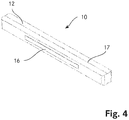
- the Fig. 4 shows a more detailed illustration of an embodiment of a pneumatic cushion 10 which can be used in a vehicle seat 1 according to the invention.
- the pneumatic cushion has a closed cover 12.
- a holding means 16 is arranged on an outer surface of the cover 12, with which the pneumatic cushion 10 can be attached to an edge of a seat surface 2 or a backrest element.
- the holding means 16 is designed as a Velcro strip.
- the sleeve 12 of the pneumatic cushion also has a predetermined folding point 17, which facilitates the folding of the sleeve 12 of the pneumatic cushion 10 during the emptying process.
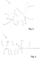
- the Fig. 5 shows a second embodiment of a vehicle seat 1 according to the invention.
- the vehicle seat of this embodiment has a second backrest element in the form of a legrest 13.
- the legrest 13 is connected to a second pivot axis 14 via a second strut 15.
- the legrest 13 can be adjusted in an angle relative to the seat surface 2 in a manner analogous to that of the backrest 3.
- the legrest 13 is at an obtuse angle b to the seat surface 2.
- the second embodiment of the vehicle seat 1 again has a first pneumatic cushion 10.1, which is arranged on an edge of the seat surface 2, which is directed toward the backrest 3.
- a first pneumatic cushion 10.1 By inflating this first pneumatic cushion 10.1, a gap between seat 2 and backrest can be closed.
- a second pneumatic cushion 10.2 is arranged on a further edge of the seat surface 2, which is directed towards the leg support 13, which is inflated during the transition to a lying position in order to fill a gap between the leg support 13 and the seat surface 2.
- a continuous, flat lying surface can be formed with the legrest 13, the seat surface 2 and the backrest 3.
Landscapes
- Engineering & Computer Science (AREA)
- Aviation & Aerospace Engineering (AREA)
- Transportation (AREA)
- Mechanical Engineering (AREA)
- Seats For Vehicles (AREA)
- Chairs For Special Purposes, Such As Reclining Chairs (AREA)
- Chair Legs, Seat Parts, And Backrests (AREA)
Description
- Die Erfindung betrifft einen Fahrzeugsitz mit mindestens einem pneumatischen Kissen, welches beim Übergang eines Lehnenelements in eine Liegeposition durch eine Pneumatikeinheit aufgeblasen und beim Übergang des Lehnenelements in eine Sitzposition entleert wird.
- Der Einsatz von pneumatischen Kissen in Fahrzeugsitzen, insbesondere im Bereich der Flugzeugsitze ist bekannt. Ein wesentlicher Vorteil von pneumatischen Kissen liegt im reduzierten Gewicht sowie der Möglichkeit, die Härte der pneumatischen Kissen in Abhängigkeit von äusseren Faktoren oder des persönlichen Geschmacks eines auf dem Fahrzeugsitz sitzenden Passagiert einstellen zu können.
- Beispielsweise beschreibt die
DE 10 2010 020 642 (Dornier Technologie GmbH & Co KG) einen Flugzeugsitz mit einem Neigungssensor für die Rückenlehne, wobei bei mindestens einem aufblasbaren Luftkissen der Druck in Abhängigkeit des gemessenen Neigungswinkels der Rückenlehne geregelt wird. Der Neigungssensor ist vorzugsweise als absoluter Neigungssensor ausgestaltet, welcher in eine Pneumatikeinheit des Sitzes integriert ist. Dadurch kann der Druck des mindestens einen aufblasbaren Luftkissens in Abhängigkeit des absoluten Lehnenwinkels in Bezug zur Horizontalen geregelt werden und nicht wie bei bekannten System anhand des relativen Winkels zwischen Rückenlehne und Sitzfläche. - Die
WO 2015/073363 offenbart Premiumsitze für Flugzeuge, welche von einer Sitzposition in eine Liegeposition überführt werden können. Die Sitze verfügen über eine Mehrzahl an aufblasbaren Kammern, welche einen schlafenden Passagier bei Bewegungen des Flugzeugs abfedern. Die Kammern werden selektiv beim Überführen der Sitze zwischen den Positionen aufgeblasen und entleert. Ein gattungsgemässer Fahrzeugsitz ist in derEP2944509 offenbart. - Aufgabe der Erfindung ist es, einen dem eingangs genannten technischen Gebiet zugehörenden Fahrzeugsitz zu schaffen, welcher in einer Liegeposition einen höheren Liegekomfort bietet.
- Die Lösung der Aufgabe ist durch die Merkmale des Anspruchs 1 definiert. Gemäss der Erfindung umfasst der Fahrzeugsitz eine Sitzfläche sowie wenigstens ein zur Sitzfläche um eine Achse schwenkbares Lehnenelement. Das wenigstens eine Lehnenelement ist von einer Sitzposition, in welcher das Lehnenelement im Wesentlichen in einem stumpfen oder überstumpfen Winkel relativ zur Sitzfläche steht, in eine Liegeposition, in welcher die Sitzfläche sowie das Lehnenelement eine im Wesentlichen plane Fläche bilden, und zurück bewegbar. Weiter verfügt der Flugzeugsitz über mindestens ein pneumatisches Kissen sowie über eine Pneumatikeinheit, welche derart ausgestaltet ist, dass diese das mindestens eine pneumatische Kissen im Wesentlichen vollständig aufbläst, wenn das wenigstens eine Lehnenelement in die Liegeposition bewegt wird, und das pneumatische Kissen im Wesentlichen vollständig entleert, wenn das wenigstens eine Lehnenelement in die Sitzposition bewegt wird. Das mindestens eine pneumatische Kissen ist in einem Randbereich der Sitzfläche oder des wenigstens einen Lehnenelements angeordnet, welcher an das wenigstens eine Lehnenelement beziehungsweise die Sitzfläche grenzt, so dass sich das mindestens eine pneumatische Kissen in der Liegeposition zwischen der Sitzfläche und dem wenigstens einen Lehnenelement erstreckt.
- Dadurch lässt sich ein allfälliger Spalt zwischen der Sitzfläche und dem wenigstens einen Lehnenelement, welcher durch die Bewegung des Lehnenelements in die Liegeposition entsteht, überbrücken. Dadurch bildet der Fahrzeugsitz in der Liegeposition für einen Passagier eine durchgehende Liegefläche, welche sich durchgehend im Wesentlichen gleich hart anfühlt.
- Vorzugsweise handelt es sich beim wenigstens einen Lehnenelement um eine Rückenlehne oder um eine Beinstütze. In einer bevorzugten Ausführungsform weist der Fahrzeugsitz zwei Lehnenelemente auf, welche eine Rückenlehne und eine Beinstütze des Fahrzeugsitzes ausbilden.
- Nebst der Sitzfläche sowie der Rückenlehne und/oder der Beinstütze umfasst der Fahrzeugsitz vorzugsweise weitere Elemente, wie zum Beispiel eine Kopfstütze, Armlehnen, einen Ottoman, etc. Die Sitzfläche sowie das wenigstens eine Lehnenelement weisen eine Polsterung auf. Diese Polsterung umfasst vorzugsweise je mindestens ein pneumatisches Kissen. Alternativ kann die Polsterung der Sitzfläche und/oder des wenigstens einen Lehnenelements auch einen Schaumstoff umfassen. Weiter alternativ kann die Polsterung der Sitzfläche und/oder des wenigstens einen Lehnenelements auch über mindestens ein pneumatisches Kissen sowie über Schaumstoff verfügen. Der Fahrzeugsitz verfügt ferner über einen Unterbau, mit welchem der Fahrzeugsitz mit einem Boden des Fahrzeugs verbunden werden kann.
- Um das wenigstens eine Lehnenelement relativ zur Sitzfläche zu verschwenken, verfügt der Fahrzeugsitz über eine entsprechende Achse sowie einen Verstellmechanismus, mit welchem sich das wenigstens eine Lehnenelement bewegen lässt. Der Verstellmechanismus erlaubt vorzugsweise in einer ersten Konfiguration eine Arretierung des wenigstens einen Lehnenelements relativ zur Sitzfläche, während der Verstellmechanismus in einer zweiten Konfiguration ein Verschwenken des wenigstens einen Lehnenelements relativ zur Sitzfläche erlaubt.
- Ist das Lehnenelement eine Rückenlehne, so steht diese in einer Sitzposition vorzugsweise in einem stumpfen Winkel relativ zur Sitzfläche. Das heisst, dass der Winkel zwischen Sitzfläche und Rückenlehne von 90° bis 180° beträgt. In speziellen Ausführungsformen kann jedoch auch vorgesehen sein, dass die Rückenlehne zusätzlich in einem spitzen Winkel, also einem Winkel zwischen 0° und 90° zur Sitzfläche stehen kann.
- Ist das Lehnenelement eine Beinstütze, so steht diese in einer Sitzposition vorzugsweise in einem überstumpfen Winkel relativ zur Sitzfläche. Das heisst, dass zwischen Sitzfläche und Beinstütze ein Winkel grösser als 180° gebildet wird. In einer Sitzposition ist die Beinstütze vorzugsweise in einem Winkel von 270° zur Sitzfläche angeordnet.
- Vorzugsweise ist der Fahrzeugsitz derart ausgestaltet, dass sich der Winkel zwischen der Sitzfläche und dem mindestens einen Lehnenelement in der Sitzposition variieren lässt. Beispielsweise kann der Verstellmechanismus derart ausgestaltet sein, dass dieser eine Arretierung des wenigstens einen Lehnenelements in einem beliebigen stumpfen beziehungsweise überstumpfen Winkel relativ zur Sitzfläche ermöglicht. Alternativ kann der Verstellmechanismus auch die Arretierung des wenigstens einen Lehnenelements nur in einer vorgegebenen Anzahl an vorbestimmten Winkeln erlauben.
- In der Liegeposition beträgt der Winkel zwischen der Sitzfläche und dem wenigstens einen Lehnenelement im Wesentlichen 180°. Dadurch bilden die Sitzfläche sowie das mindestens eine Lehnenelement für den auf dem Fahrzeugsitz sitzenden, respektive in dieser Position liegenden Passagier eine im Wesentlichen plane Liegefläche.
- In der vorliegenden Anmeldung wird unter "im Wesentlichen plan" eine flache Ebene verstanden, wobei diese Ebene je nach Konturierung der Sitzfläche respektive des wenigstens einen Lehnenelements auch gewisse Bereiche aufweisen kann, welche eine leichte Krümmung aufweisen, beispielsweise zur Mitte der Sitzfläche respektive des Lehnenelements hin. Ferner kann aufgrund eines Spiels an der Schwenkachse des mindestens einen Lehnenelements beim Übergang zwischen der Sitzfläche und des Lehnenelements ein kleiner Höhenversatz vorhanden sein.
- Als "pneumatisches Kissen" wird in der vorliegenden Anmeldung ein von mindestens zwei in ihren Randbereichen luftdicht miteinander verbundenen flexiblen Seitenflächen gebildetes Kissen verstanden, in dessen Volumen Luft gepumpt werden kann, um ein dreidimensionales weiches Gebilde mit Polsterungseigenschaften zu erhalten. Die Seitenflächen liegen vorzugsweise als einzelne Flächenelemente vor. Alternativ können die mindestens zwei Seitenflächen aus einem einzelnen Flächenelement bestehen, welches über entsprechende Faltungen verfügt.
- Ferner wird unter dem Begriff "pneumatisches Kissen" in der vorliegenden Anmeldung auch ein zylindrisches Volumen verstanden, welches durch ein einzelnes, gebogenes und an drei Kanten mit sich selbst luftdicht verbundenes Flächenelement umhüllt ist.
- Insbesondere bevorzugt ist das mindestens eine pneumatische Kissen im Wesentlichen quaderförmig und weist daher sechs Seitenflächen auf, welche insbesondere durch sechs separate Flächenelemente gebildet werden. In alternativen Varianten kann das mindestens eine pneumatische Kissen jedoch auch rund, oval oder beliebig polygonal ausgebildet sein.
- Die mindestens zwei Seitenflächen umfassen vorzugsweise mindestens ein Polymermaterial. Alternativ können die mindestens zwei Seitenflächen auch ein Textil umfassen, wobei in diesem Fall das Textil mit einer luftdichten Schicht versehen ist. Die mindestens zwei Seitenflächen verfügen vorzugsweise über Sollfaltstellen, so dass sich diese bei der Entleerung in einer vorbestimmten Weise zusammenfalten. Alternativ können die mindestens zwei Seitenflächen auch aus einem elastischen Material bestehen.
- Die Pneumatikeinheit verfügt vorzugsweise über eine Pumpe, mit welcher sich Luft in das mindestens eine pneumatische Kissen fördern lässt. Ferner verfügt die Pneumatikeinheit auch über mindestens ein Ventil, mit welchem sich die Pumpe selektiv über mindestens eine Fluidleitung mit dem mindestens einen pneumatischen Kissen fluidisch in Verbindung bringen lässt. Vorzugsweise verfügt die Pneumatikeinheit über eine Steuerung, mit welcher sich die Pumpe und das mindestens eine Ventil ansteuern lassen.
- Umfasst der Fahrzeugsitz mehrere pneumatische Kissen, so sind diese vorzugsweise über einen Ventilblock, bei welchem pro pneumatisches Kissen mindestens ein Ventil vorhanden ist, mit der Pumpe verbunden. Alternativ können auch mehrere pneumatische Kissen über dasselbe Ventil mit der Pumpe verbunden sein. Die Pneumatikeinheit kann insbesondere auch zum Anpassen des Füllvolumens von pneumatischen Kissen in der Polsterung des Fahrzeugsitzes eingesetzt werden. So lässt sich mit nur einer Pneumatikeinheit eine Vielzahl an Komfortfunktionen steuern.
- Vorzugsweise ist jedem Fahrzeugsitz eine Pneumatikeinheit zugeordnet. Alternativ kann jedoch auch vorgesehen sein, dass zwei oder mehr Fahrzeugsitze, welche beispielsweise als Sitzreihe nebeneinander angeordnet sind, eine gemeinsame Pneumatikeinheit aufweisen. Ferner können pro Fahrzeugsitz auch mehrere Pneumatikeinheiten vorhanden sein, beispielsweise pro vorhandenem pneumatischen Kissen eine Pneumatikeinheit.
- Vorzugsweise verfügt der Fahrzeugsitz über einen Sensor, mit welchem sich ein Übergang des mindestens einen Lehnenelements zwischen der Sitzposition und der Liegeposition oder umgekehrt detektieren lässt, um das mindestens eine pneumatische Kissen entsprechend aufzublasen respektive zu entleeren. Der Sensor ist vorzugsweise mit der Pneumatikeinheit elektrisch verbunden um entsprechende Sensordaten an diese zu übermitteln. Vorzugsweise wird das Aufblasen beziehungsweise Entleeren des mindestens einen pneumatischen Kissens durch eine elektronische Eingabeeinheit, welche durch einen Benutzer des Fahrzeugsitzes bedient werden kann, in Abhängigkeit der durch den Benutzer eingestellten Winkelposition des wenigstens einen Lehnenelements gesteuert.
- Das mindestens eine pneumatische Kissen ist vorzugsweise an einer Kante der Sitzfläche und/oder des wenigstens einen Lehnenelements angeordnet. Insbesondere bevorzugt ist das mindestens eine pneumatische Kissen mit einer Polsterung der Sitzfläche und/oder des Lehnenelements verklebt oder verschweisst. Dadurch lässt sich eine besonders feste Verbindung zwischen dem mindestens einen pneumatischen Kissen und der Sitzfläche beziehungsweise dem Lehnenelement erzielen. Alternativ kann das mindestens eine pneumatische Kissen jedoch auch durch andere Verbindungstechniken, wie beispielseiwese durch eine Naht, einen Reiss- oder einen Klettverschluss mit der Sitzfläche und/oder mit dem wenigstens einen Lehnenelement verbunden sein. In einer weiteren bevorzugten Ausführungsform kann das mindestens eine pneumatische Kissen auch lose innerhalb eines Bezugs, welcher die Sitzfläche sowie das mindestens eine Lehnenelement umgibt, angeordnet sein, beispielsweise innerhalb einer flammfesten Textilummantelung.
- Vorzugsweise verfügt der Fahrzeugsitz über mindestens einen Textilbezug, welcher über die Sitzfläche und das wenigstens eine Lehnenelement sowie das mindestens eine pneumatische Kissen gespannt ist. Dadurch wird eine optisch einheitliche Fläche erzielt. Ferner schützt der mindestens eine Textilbezug die Polsterung sowie das mindestens eine pneumatische Kissen vor Verschmutzungen und/oder Beschädigungen. Ferner ist vorzugsweise eine flammenhemmende Schicht, insbesondere eine flammfeste Textilummantelung um die Sitzfläche, das wenigstens eine Lehnenelement sowie das mindestens eine pneumatischen Kissen angebracht, um die Sicherheit zu erhöhen, was insbesondere bei Massenverkehrsmitteln wichtig und auch vorgeschrieben ist.
- Der erfindungsgemässe Fahrzeugsitz wird vorzugsweise in Massenverkehrsmitteln wie Züge, Busse, Schiffe oder Flugzeuge eingesetzt. Alternativ kann der erfindungsgemässe Fahrzeugsitz jedoch auch in privaten Verkehrsmitteln wie PKW oder LKW eingesetzt werden.
- Vorzugsweise verfügt der Fahrzeugsitz über einen Aktuator, mit welchem sich der Winkel des mindestens einen Lehnenelements relativ zur Sitzfläche motorisch verstellen lässt, wobei die Pneumatikeinheit anhand des Status dieses Aktuators das mindestens eine pneumatische Kissen aufbläst respektive entleert.
- Die Verwendung eines Aktuators erhöht den Komfort, da eine Verstellung des mindestens einen Lehnenelements in die Liegeposition und zurück in die Sitzposition per Knopfdruck erfolgen kann. In einer weiter bevorzugten Ausführungsform kann der Aktuator auch die Sitzfläche linear entlang der Sitzrichtung verschieben, so dass je nach Platzverhältnissen eine optimale Konfiguration des Fahrzeugsitzes erzielt werden kann. Falls der Fahrzeugsitz noch über weitere Elemente verfügt, können diese ebenfalls über den Aktuator oder über zusätzliche Aktuatoren bewegt werden.
- Geeignete Aktuatoren für Fahrzeugsitze sind einem Fachmann auf dem Gebiet bekannt. Beispielsweise können als Aktuatoren durch einen Motor angetriebene Spindeln verwendet werden.
- Die Pneumatikeinheit ist vorzugsweise mit einer Steuerung des Aktuators verbunden, so dass diese ein Signal, welches den Übergang zur Liegeposition signalisiert, von der Steuerung erhält. Alternativ verfügt die Pneumatikeinheit über einen Sensor, welcher die relative Position eines bewegbaren Teils des Aktuators, beispielsweise eine Spindel, misst. Beim durch den Sensor detektierten Durchgang durch eine bestimmte Position dieses bewegbaren Teils werden das Aufblasen respektive das Entleeren des mindestens einen pneumatischen Kissens ausgelöst. In einer weiteren alternativen Ausführungsform kann auch ein Sensor am Fahrzeugsitz angeordnet sein, welcher die relative Position des wenigstens einen Lehnenelements misst und entsprechend Signale an die Pneumatikeinheit sendet.
- Vorzugsweise verfügt die Pneumatikeinheit über eine Pumpe, mit welcher sich das mindestens eine pneumatische Kissen sowohl aufblasen wie auch entleeren lässt.
- Dadurch ist eine aktive Entleerung des mindestens einen pneumatischen Kissens durch die Pumpe möglich, was den Entleerungsvorgang erheblich beschleunigt. Hierzu wird insbesondere bevorzugt eine Pumpe mit zwei Förderrichtungen eingesetzt.
- Als "Pumpe mit zwei Förderrichtungen" im Sinne der vorliegenden Anmeldung wird eine Pumpe verstanden, welche im Stande ist, das pneumatische Kissen sowohl aufzupumpen wie auch aktiv zu entleeren.
- Alternativ kann auch eine Pumpe mit nur einer Förderrichtung eingesetzt werden, wobei in diesem Fall ein aktives Entleeren des mindestens einen pneumatischen Kissens durch eine entsprechende Anordnung von Leitungen und Ventilen erzielt werden kann.
- Vorzugsweise wird als Pumpe eine Membranpumpe eingesetzt. Die Membranpumpe umfasst bevorzugt einen elektrischen Antrieb.
- Alternativ kann es sich bei der Pumpe auch um eine Strömungspumpe handeln, welche ein kontinuierliches Fördern des Fluids ermöglicht. Die Pumpe kann beispielsweise als Rotationskolbenpumpe, Drehschieberpumpe oder Impellerpumpe ausgestaltet sein.
- Vorzugsweise verfügt das mindestens eine pneumatische Kissen über einen Drucksensor, der den im Innern des mindestens einen pneumatischen Kissens vorherrschenden Druck misst, wobei die Pneumatikeinheit derart ausgestaltet ist, dass diese bei Überschreiten oder Unterschreiten eines vorgegebenen Solldrucks das mindestens eine pneumatische Kissen entleert beziehungsweise aufbläst, bis der Solldruck erreicht wird.
- Dies erhöht die Sicherheit sowie den Komfort eines auf dem Fahrzeugsitz sitzenden Passagiers, da die in dem mindestens einen pneumatischen Kissen vorhandene Luftmenge nachgeregelt wird, zum Beispiel falls das mindestens eine pneumatische Kissen beim Aufblasen unerwartet auf ein im Weg stehendes Objekt trifft. Durch ein solches Objekt kann sich das mindestens eine pneumatische Kissen nicht auf sein vollständiges Volumen entfalten, wodurch bei einem gleichbleibenden Luftvolumen der Innendruck ansteigt. Dies kann dazu führen, dass sich das mindestens eine pneumatische Kissen für einen Passagier im Vergleich zum Rest des Sitzes als zu hart anfühlt. Ferner kann ein zu grosser Überdruck auch zu einer Beschädigung oder gar zu einem Platzen des mindestens einen pneumatischen Kissens führen. Mit einer aktiven Nachregelung des Innendruckes auf einen vorgegebenen Solldruck werden diese Nachteile verhindert.
- Ferner lassen sich mit dieser Ausführungsform bei Flugzeugsitzen auch Druckunterschiede, welche vom sich in Abhängigkeit der Flugphase verändernden Kabinendruck stammen, ausgleichen, wodurch sich das mindestens eine pneumatische Kissen für einen Passagier immer gleich hart anfühlt.
- Der Drucksensor ist vorzugsweise innerhalb des pneumatischen Kissens angeordnet. Alternativ kann der Drucksensor jedoch auch in einer Leitung oder einem Ventilblock zwischen der Pumpe und dem pneumatischen Kissen angeordnet sein. Es muss lediglich sichergestellt werden, dass der Drucksensor den innerhalb des pneumatischen Kissens vorherrschenden Druck messen kann.
- Die vorliegende Anmeldung bezieht sich ferner auf die Verwendung eines erfindungsgemässen Fahrzeugsitzes in einem Flugzeug. Bei der Verwendung in einem Flugzeug verfügt der erfindungsgemässe Fahrzeugsitz vorzugsweise über eine Polsterung, welche mindestens ein pneumatisches Kissen verfügt, um das Gesamtgewicht des Fahrzeugsitzes zu senken.
- Aus der nachfolgenden Detailbeschreibung und der Gesamtheit der Patentansprüche ergeben sich weitere vorteilhafte Ausführungsformen und Merkmalskombinationen der Erfindung.
- Die zur Erläuterung des Ausführungsbeispiels verwendeten Zeichnungen zeigen:
- Fig. 1
- eine schematische Darstellung eines Fahrzeugsitzes aus dem Stand der Technik mit der Rückenlehne in einer Sitzposition;
- Fig. 2
- den Fahrzeugsitz aus der
Fig. 1 in der Liegeposition; - Fig. 3
- eine erste Ausführungsform des erfindungsgemässen Fahrzeugsitzes in der Liegeposition;
- Fig. 4
- eine detaillierte Darstellung eines pneumatischen Kissens;
- Fig. 5
- eine zweite Ausführungsform des erfindungsgemässen Fahrzeugsitzes in einer Sitzposition;
- Fig. 6
- der Fahrzeugsitz gemäss
Fig. 5 in der Liegeposition. - Grundsätzlich sind in den Figuren gleiche Teile mit gleichen Bezugszeichen versehen.
- Die
Fig. 1 zeigt schematisch einen Fahrzeugsitz 1 gemäss dem Stand der Technik. Der Fahrzeugsitz 1 verfügt über eine Sitzfläche 2 mit einer Polsterung sowie über eine Rückenlehne 3 mit einer Polsterung. Die Rückenlehne 3 stellt dabei ein relativ zur Sitzfläche 2 verstellbares Lehnenelement dar. Der Fahrzeugsitz 1 verfügt über einen Unterbau 4, der hier nur angedeutet dargestellt ist. Die Rückenlehne 3 befindet sich in derFig. 1 in der Sitzposition, wobei die Rückenlehne 3 in einem stumpfen Winkel a zur Sitzfläche 2 steht. Weiter ist die Rückenlehne 3 über eine Strebe 5 mit einer Schwenkachse 6 verbunden, welche ein Verschwenken der Rückenlehne 3 relativ zur Sitzfläche 2 ermöglicht. Dadurch kann die Rückenlehne 3 unterschiedliche Winkel a relativ zur Sitzfläche 2 einnehmen. Auf die Schwenkachse 6 wirkt ein Verstellmechanismus (nicht gezeigt), welcher eine Arretierung der Rückenlehne in unterschiedlichen Winkeln a relativ zur Sitzfläche 2 ermöglicht. Der Verstellmechanismus kann über einen Aktuator verfügen, mit welchem sich die Rückenlehne 3 motorisch relativ zur Sitzfläche 2 verschwenken lässt. - Die
Fig. 2 zeigt den Fahrzeugsitz 1 gemäss derFig. 1 mit der Rückenlehne 3 in einer Liegeposition, wobei die Rückenlehne 3 und die Sitzfläche 2 eine im Wesentlichen plane Liegefläche für einen auf dem Fahrzeugsitz sitzenden Passagier (nicht gezeigt) bilden. Durch die Anordnung der Schwenkachse 6 am Unterbau 4 entsteht beim Verschwenken der Rückenlehne 3 eine Lücke 7 zwischen der Sitzfläche 2 und der Rückenlehne 3. Diese Lücke 7 fühlt sich für einen auf dem Fahrzeugsitz liegenden Passagier (nicht gezeigt) unangenehm an. - Die
Fig. 3 zeigt eine erste Ausführungsform eines erfindungsgemässen Fahrzeugsitzes 1. Um die Lücke 7 gemässFig. 2 zu schliessen, verfügt der erfindungsgemässe Fahrzeugsitz 1 über ein pneumatisches Kissen 10, welches in einem hinteren Randbereich 8 der Sitzfläche, welcher an die Rückenlehne 3 - dem Lehnenelement des Fahrzeugsitzes 1 - grenzt, an der Kante befestigt ist. Beim Übergang der Rückenlehne 3 in die Liegeposition wird das pneumatische Kissen 10 durch eine Pneumatikeinheit 9 aufgeblasen. Das pneumatische Kissen 10 ist dabei derart ausgestaltet, dass dieses im aufgeblasenen Zustand mit der Sitzfläche 2 und der Rückenlehne 3 eine plane Fläche bildet. Über die Pneumatikeinheit 9 können noch weitere pneumatische Kissen (nicht gezeigt), welche am Sitz oder in der Polsterung der Sitzfläche 2 und/oder der Rückenlehne 3 angeordnet sind, aufgeblasen beziehungsweise entleert werden. - Die
Fig. 4 zeigt eine detailliertere Darstellung einer Ausführungsform eines pneumatischen Kissens 10, welches in einem erfindungsgemässen Fahrzeugsitz 1 verwendet werden kann. Das pneumatische Kissen verfügt über eine geschlossene Hülle 12. An einer Aussenfläche der Hülle 12 ist ein Haltemittel 16 angeordnet, mit welchem sich das pneumatische Kissen 10 an einer Kante einer Sitzfläche 2 oder eines Lehnenelements befestigen lässt. In der gezeigten Ausführungsform ist das Haltemittel 16 als Klettband ausgestaltet. Die Hülle 12 des pneumatischen Kissens weist ferner eine Sollfaltstelle 17 auf, welche das Zusammenfalten der Hülle 12 des pneumatischen Kissens 10 während des Entleerungsvorgangs erleichtert. - Die
Fig. 5 zeigt eine zweite Ausführungsform eines erfindungsgemässen Fahrzeugsitzes 1. Im Unterschied zur Ausführungsform gemäss derFig. 3 verfügt der Fahrzeugsitz dieser Ausführungsform nebst der Rückenlehne 3 über ein zweites Lehnenelement in der Form einer Beinstütze 13. Die Beinstütze 13 ist über eine zweite Strebe 15 mit einer zweiten Schwenkachse 14 verbunden. Die Beinstütze 13 lässt sich in analoger Weise wie die Rückenlehne 3 im Winkel relativ zur Sitzfläche 2 verstellen. Die Beinstütze 13 steht dabei in einem überstumpfen Winkel b zur Sitzfläche 2. - Wie die
Fig. 6 zeigt, verfügt die zweite Ausführungsform des erfindungsgemässen Fahrzeugsitzes 1 wiederum über ein erstes pneumatisches Kissen 10.1, welches an einer Kante der Sitzfläche 2 angeordnet ist, welche zur Rückenlehne 3 hin gerichtet ist. Durch Aufblasen dieses ersten pneumatischen Kissens 10.1 lässt sich eine Lücke zwischen Sitzfläche 2 und Rückenlehne schliessen. Gleichermassen ist an einer weiteren Kante der Sitzfläche 2, welche zur Beinstütze 13 hin gerichtet ist, ein zweites pneumatisches Kissen 10.2 angeordnet, welches beim Übergang in eine Liegeposition aufgeblasen wird, um eine Lücke zwischen der Beinstütze 13 und der Sitzfläche 2 zu füllen. Mittels der zwei pneumatischen Kissen 10.1, 10.2 lässt sich so mit der Beinstütze 13, der Sitzfläche 2 sowie der Rückenlehne 3 eine durchgehende, ebene Liegefläche bilden.
Claims (6)
- Fahrzeugsitz umfassend eine Sitzfläche (2) sowie wenigstens ein zur Sitzfläche (2) um eine Achse (6) schwenkbares Lehnenelement (3, 13), wobei das wenigstens eine Lehnenelement (3, 13) von einer Sitzposition, in welcher das Lehnenelement (3, 13) im Wesentlichen in einem stumpfen oder überstumpfen Winkel (a, b) relativ zur Sitzfläche (2) steht, in eine Liegeposition, in welcher die Sitzfläche (2) sowie das wenigstens eine Lehnenelement (3, 13) eine im Wesentlichen plane Fläche bilden, und zurück bewegbar ist, und wobei der Fahrzeugsitz (1) über mindestens ein pneumatisches Kissen (10; 10.1, 10.2) sowie über eine Pneumatikeinheit (9) verfügt, welche derart ausgestaltet ist, dass diese das mindestens eine pneumatische Kissen (10; 10.1, 10.2) im Wesentlichen vollständig aufbläst, wenn das wenigstens eine Lehnenelement (3, 13) in die Liegeposition bewegt wird, und das mindestens eine pneumatische Kissen (10; 10.1, 10.2) im Wesentlichen vollständig entleert, wenn das wenigstens eine Lehnenelement (3, 13) in die Sitzposition bewegt wird, dadurch gekennzeichnet, dass das mindestens eine pneumatische Kissen (10; 10.1, 10.2) in einem Randbereich (8) der Sitzfläche (2) oder des wenigstens einen Lehnenelements (3, 13) angeordnet ist, welcher an das wenigstens eine Lehnenelement (3, 13) beziehungsweise die Sitzfläche (2) grenzt, so dass sich das mindestens eine pneumatische Kissen (10; 10.1, 10.2) in der Liegeposition zwischen der Sitzfläche (2) und dem wenigstens einen Lehnenelement (3, 13) erstreckt.
- Fahrzeugsitz gemäss Anspruch 1, dadurch gekennzeichnet, dass das wenigstens eine Lehnenelement eine Rückenlehne (3), eine Beinstütze (13) oder beides ist.
- Fahrzeugsitz gemäss einem der Ansprüche 1 oder 2, dadurch gekennzeichnet, dass der Fahrzeugsitz (1) über einen Aktuator verfügt, mit welchem sich der Winkel (a) des wenigstens einen Lehnenelements (3, 13) relativ zur Sitzfläche (2) motorisch verstellen lässt, wobei die Pneumatikeinheit (9) derart ausgestaltet ist, dass diese anhand des Status des Aktuators das mindestens eine pneumatische Kissen (10; 10.1, 10.2) aufbläst respektive entleert.
- Fahrzeugsitz gemäss einem der Ansprüche 1 bis 3, dadurch gekennzeichnet, dass die Pneumatikeinheit (9) über eine Pumpe verfügt, mit welcher sich das mindestens eine pneumatische Kissen (10; 10.1, 10.2) sowohl aufblasen wie auch entleeren lässt.
- Fahrzeugsitz gemäss einem der Ansprüche 1 bis 4, dadurch gekennzeichnet, dass das mindestens eine pneumatische Kissen (10; 10.1, 10.2) über einen Drucksensor verfügt, der den im Innern des mindestens einen pneumatischen Kissens (10; 10.1, 10.2) vorherrschenden Druck misst und die Pneumatikeinheit (9) derart ausgestaltet ist, dass diese bei Überschreiten oder Unterschreiten eines vorgegebenen Solldrucks das mindestens eine pneumatische Kissen (10; 10.1, 10.2) entleert beziehungsweise aufbläst, bis der Solldruck erreicht wird.
- Verwendung eines Fahrzeugsitzes gemäss einem der Ansprüche 1 bis 5 in einem Flugzeug.
Applications Claiming Priority (2)
| Application Number | Priority Date | Filing Date | Title |
|---|---|---|---|
| CH00433/16A CH712316A1 (de) | 2016-04-04 | 2016-04-04 | Fahrzeugsitz mit mindestens einem pneumatischen Kissen. |
| PCT/EP2016/080308 WO2017174168A1 (de) | 2016-04-04 | 2016-12-08 | Fahrzeugsitz mit mindestens einem pneumatischen kissen |
Publications (2)
| Publication Number | Publication Date |
|---|---|
| EP3439909A1 EP3439909A1 (de) | 2019-02-13 |
| EP3439909B1 true EP3439909B1 (de) | 2020-02-19 |
Family
ID=56068561
Family Applications (1)
| Application Number | Title | Priority Date | Filing Date |
|---|---|---|---|
| EP16808668.4A Active EP3439909B1 (de) | 2016-04-04 | 2016-12-08 | Fahrzeugsitz mit mindestens einem pneumatischen kissen |
Country Status (6)
| Country | Link |
|---|---|
| US (1) | US10967976B2 (de) |
| EP (1) | EP3439909B1 (de) |
| JP (1) | JP2019513614A (de) |
| CN (1) | CN109070776A (de) |
| CH (1) | CH712316A1 (de) |
| WO (1) | WO2017174168A1 (de) |
Cited By (1)
| Publication number | Priority date | Publication date | Assignee | Title |
|---|---|---|---|---|
| DE102024124003A1 (de) | 2024-08-22 | 2026-02-26 | Audi Aktiengesellschaft | Kraftfahrzeug |
Families Citing this family (4)
| Publication number | Priority date | Publication date | Assignee | Title |
|---|---|---|---|---|
| DE102019204488B4 (de) * | 2019-03-29 | 2023-05-04 | Adient Aerospace, Llc | Sitz, insbesondere Flugzeugsitz |
| US11192653B2 (en) * | 2020-01-21 | 2021-12-07 | B/E Aerospace, Inc. | Pneumatically actuated vehicle seat assemblies |
| NL2029709B1 (nl) * | 2021-11-11 | 2023-06-08 | Automotive Fryslan B V | Slaapbank voor een voertuig |
| CN116901801B (zh) * | 2023-08-09 | 2025-12-30 | 浙江极氪智能科技有限公司 | 汽车座椅和车辆 |
Family Cites Families (23)
| Publication number | Priority date | Publication date | Assignee | Title |
|---|---|---|---|---|
| US4629248A (en) * | 1985-06-03 | 1986-12-16 | General Motors Corporation | Thigh support for vehicle seats |
| DE3631872C1 (de) * | 1986-09-19 | 1987-10-01 | Daimler Benz Ag | Fahrzeugsitz |
| US5370444A (en) * | 1992-09-11 | 1994-12-06 | Sears Manufacturing Company | Adjustable cushion |
| JPH0747016A (ja) * | 1993-08-05 | 1995-02-21 | Nissan Motor Co Ltd | 座席装置 |
| DE4431573A1 (de) * | 1994-09-05 | 1995-03-30 | Gian Hung Chang | Fahrzeugsitz |
| US5788329A (en) * | 1996-02-08 | 1998-08-04 | Pilarczyk; Ervin Robert | Fold-down seat for a motor vehicle |
| US5975636A (en) * | 1997-08-12 | 1999-11-02 | Koch; Roger | Assembly for filling void between cushions of reclining seats |
| FR2776586B1 (fr) * | 1998-03-30 | 2000-06-09 | Adder Sa | Dispositif de conversion de sieges en couchettes, siege destine a un tel dispositif et moyen de transport ainsi equipe |
| GB9918263D0 (en) * | 1999-08-04 | 1999-10-06 | Britax Rumbold Ltd | Seating unit of a passenger vehicle |
| CA2581738C (en) * | 2001-08-09 | 2009-04-14 | Virgin Atlantic Airways Limited | A seating system and a passenger accomodation unit for a vehicle |
| FR2840282B1 (fr) * | 2002-05-31 | 2004-07-30 | Sicma Aero Seat | Siege transformable en couchette a accoudoir deformable |
| US20080100109A1 (en) * | 2006-10-11 | 2008-05-01 | Neil Michael Frank | Integrated child car seat |
| CA2750767C (en) * | 2009-01-30 | 2018-04-10 | Air New Zealand Limited | Seating arrangement, seat unit, tray table and seating system |
| GB0903744D0 (en) * | 2009-03-04 | 2009-04-15 | Virgin Atlantic Airways Ltd | A seating insallation for a passenger vehicle |
| DE102010020642A1 (de) | 2010-05-15 | 2011-11-17 | Dornier Technologie Gmbh & Co. Kg | Pneumatiksteuerung für Fahrzeugsitz, insbesondere Fluggastsitz |
| US20130256072A1 (en) * | 2012-04-02 | 2013-10-03 | Modrek Farhat | Luggage Having A Folded Bed |
| US9039085B2 (en) * | 2012-06-04 | 2015-05-26 | Ford Global Technologies, Llc | Seat extension seamless gap fill |
| US9228885B2 (en) * | 2012-06-21 | 2016-01-05 | Hill-Rom Services, Inc. | Patient support systems and methods of use |
| US9090185B2 (en) * | 2013-03-14 | 2015-07-28 | Leggett & Platt Canada Co. | Seat with pneumatic headrest and thigh adjustment |
| WO2015073363A1 (en) | 2013-11-12 | 2015-05-21 | B/E Aerospace, Inc. | Aircraft seat with taxi, takeoff and landing lie flat position capability |
| EP2944510A1 (de) | 2014-05-14 | 2015-11-18 | Lantal Textiles AG | Fahrzeugsitz mit einstellbarer Sitzfläche |
| EP2944509B1 (de) | 2014-05-14 | 2017-12-20 | Lantal Textiles AG | Fahrzeugsitz mit bewegbarer Lehne |
| US9527417B2 (en) * | 2015-02-17 | 2016-12-27 | Ford Global Technologies, Llc | Air-suspended seat surfaces for folding vehicle seats |
-
2016
- 2016-04-04 CH CH00433/16A patent/CH712316A1/de unknown
- 2016-12-08 JP JP2018552044A patent/JP2019513614A/ja active Pending
- 2016-12-08 US US16/090,854 patent/US10967976B2/en active Active
- 2016-12-08 WO PCT/EP2016/080308 patent/WO2017174168A1/de not_active Ceased
- 2016-12-08 CN CN201680084261.3A patent/CN109070776A/zh active Pending
- 2016-12-08 EP EP16808668.4A patent/EP3439909B1/de active Active
Non-Patent Citations (1)
| Title |
|---|
| None * |
Cited By (1)
| Publication number | Priority date | Publication date | Assignee | Title |
|---|---|---|---|---|
| DE102024124003A1 (de) | 2024-08-22 | 2026-02-26 | Audi Aktiengesellschaft | Kraftfahrzeug |
Also Published As
| Publication number | Publication date |
|---|---|
| CN109070776A (zh) | 2018-12-21 |
| CH712316A1 (de) | 2017-10-13 |
| EP3439909A1 (de) | 2019-02-13 |
| WO2017174168A1 (de) | 2017-10-12 |
| US10967976B2 (en) | 2021-04-06 |
| JP2019513614A (ja) | 2019-05-30 |
| US20190106214A1 (en) | 2019-04-11 |
Similar Documents
| Publication | Publication Date | Title |
|---|---|---|
| EP3439909B1 (de) | Fahrzeugsitz mit mindestens einem pneumatischen kissen | |
| DE102016104908B4 (de) | Mehrschichtiger Sitz | |
| EP3142892B1 (de) | Fahrzeugsitz mit einstellbarer sitzfläche und verfahren zum verstellen einer einstellbaren sitzfläche | |
| EP2944509B1 (de) | Fahrzeugsitz mit bewegbarer Lehne | |
| EP2414191B1 (de) | Sitz mit einer auflage und verfahren zur anpassung der kontur des sitzes | |
| DE102007007116B4 (de) | Fahrzeugsitzanordnung mit beweglichen Polstern | |
| DE102009048734A1 (de) | Sitzpolster mit Blasenelementen | |
| DE102013207858A1 (de) | Autositz mit einstellbarer festigkeit | |
| DE102012208725A1 (de) | Rückenlehne für einen Fahrzeugsitz | |
| DE102008028353A1 (de) | Fahrzeugsitz | |
| AT502779A1 (de) | System zur automatischen verstellung der sitz-kontur sowie sitz, insbesonders fahrzeugsitz für automobile, flugzeuge oder dergleichen | |
| DE102010021067A1 (de) | Fahrzeugsitz mit formveränderlichen Seitenwangen | |
| EP3693274B1 (de) | Flugzeugsitz-massagesystem und flugzeugsitz mit einem massagesystem | |
| DE102016221508A1 (de) | Verstellbarer Fahrzeugsitz | |
| DE102018118157A1 (de) | Aktive einstellung eines sitzpolsters auf grundlage eines druckkennfelds für einen insassen und verfahren | |
| EP2719622A2 (de) | Flugzeugsitz | |
| DE202018105787U1 (de) | Auslassleitung für aufpumpbare Sitze | |
| CH711796A1 (de) | Pneumatisches Kissen mit Pumpeneinheit. | |
| DE102016202089A1 (de) | Fahrzeug, insbesondere Schienenfahrzeug, mit zumindest einem Sitz | |
| DE102016224885B4 (de) | Fahrzeugsitz und Verfahren zur individuellen Anpassung seiner Sitz- und/oder Lehnflächenkontur an einen Sitzbenutzer | |
| EP4308415B1 (de) | Verstellanordnung zur verstellung mindestens eines sitzkonturbereichs eines fahrzeugsitzes für ein fahrzeug, fahrzeugsitz mit der verstellanordnung und fahrzeug mit dem fahrzeugsitz | |
| DE102019132647B4 (de) | Fahrzeugsitz mit einer Kopfstütze mit entfaltbarem Kissen | |
| DE102016007491B4 (de) | Fahrzeugsitz und Kraftfahrzeug umfassend einen Fahrzeugsitz | |
| EP1724193A1 (de) | Fluggastsitz | |
| EP2944570A1 (de) | Liege zum Einsatz in einem Flugzeug |
Legal Events
| Date | Code | Title | Description |
|---|---|---|---|
| STAA | Information on the status of an ep patent application or granted ep patent |
Free format text: STATUS: UNKNOWN |
|
| STAA | Information on the status of an ep patent application or granted ep patent |
Free format text: STATUS: THE INTERNATIONAL PUBLICATION HAS BEEN MADE |
|
| PUAI | Public reference made under article 153(3) epc to a published international application that has entered the european phase |
Free format text: ORIGINAL CODE: 0009012 |
|
| STAA | Information on the status of an ep patent application or granted ep patent |
Free format text: STATUS: REQUEST FOR EXAMINATION WAS MADE |
|
| 17P | Request for examination filed |
Effective date: 20180724 |
|
| AK | Designated contracting states |
Kind code of ref document: A1 Designated state(s): AL AT BE BG CH CY CZ DE DK EE ES FI FR GB GR HR HU IE IS IT LI LT LU LV MC MK MT NL NO PL PT RO RS SE SI SK SM TR |
|
| AX | Request for extension of the european patent |
Extension state: BA ME |
|
| DAV | Request for validation of the european patent (deleted) | ||
| DAX | Request for extension of the european patent (deleted) | ||
| RIC1 | Information provided on ipc code assigned before grant |
Ipc: B60N 2/90 20180101ALI20190716BHEP Ipc: B60N 2/34 20060101AFI20190716BHEP |
|
| GRAJ | Information related to disapproval of communication of intention to grant by the applicant or resumption of examination proceedings by the epo deleted |
Free format text: ORIGINAL CODE: EPIDOSDIGR1 |
|
| GRAP | Despatch of communication of intention to grant a patent |
Free format text: ORIGINAL CODE: EPIDOSNIGR1 |
|
| GRAP | Despatch of communication of intention to grant a patent |
Free format text: ORIGINAL CODE: EPIDOSNIGR1 |
|
| STAA | Information on the status of an ep patent application or granted ep patent |
Free format text: STATUS: GRANT OF PATENT IS INTENDED |
|
| INTG | Intention to grant announced |
Effective date: 20191108 |
|
| INTC | Intention to grant announced (deleted) | ||
| INTG | Intention to grant announced |
Effective date: 20191119 |
|
| GRAS | Grant fee paid |
Free format text: ORIGINAL CODE: EPIDOSNIGR3 |
|
| GRAA | (expected) grant |
Free format text: ORIGINAL CODE: 0009210 |
|
| STAA | Information on the status of an ep patent application or granted ep patent |
Free format text: STATUS: THE PATENT HAS BEEN GRANTED |
|
| AK | Designated contracting states |
Kind code of ref document: B1 Designated state(s): AL AT BE BG CH CY CZ DE DK EE ES FI FR GB GR HR HU IE IS IT LI LT LU LV MC MK MT NL NO PL PT RO RS SE SI SK SM TR |
|
| REG | Reference to a national code |
Ref country code: CH Ref legal event code: NV Representative=s name: KELLER AND PARTNER PATENTANWAELTE AG, CH Ref country code: CH Ref legal event code: EP |
|
| REG | Reference to a national code |
Ref country code: DE Ref legal event code: R096 Ref document number: 502016008853 Country of ref document: DE |
|
| REG | Reference to a national code |
Ref country code: AT Ref legal event code: REF Ref document number: 1234571 Country of ref document: AT Kind code of ref document: T Effective date: 20200315 |
|
| REG | Reference to a national code |
Ref country code: IE Ref legal event code: FG4D Free format text: LANGUAGE OF EP DOCUMENT: GERMAN |
|
| REG | Reference to a national code |
Ref country code: NL Ref legal event code: MP Effective date: 20200219 |
|
| PG25 | Lapsed in a contracting state [announced via postgrant information from national office to epo] |
Ref country code: FI Free format text: LAPSE BECAUSE OF FAILURE TO SUBMIT A TRANSLATION OF THE DESCRIPTION OR TO PAY THE FEE WITHIN THE PRESCRIBED TIME-LIMIT Effective date: 20200219 Ref country code: RS Free format text: LAPSE BECAUSE OF FAILURE TO SUBMIT A TRANSLATION OF THE DESCRIPTION OR TO PAY THE FEE WITHIN THE PRESCRIBED TIME-LIMIT Effective date: 20200219 Ref country code: NO Free format text: LAPSE BECAUSE OF FAILURE TO SUBMIT A TRANSLATION OF THE DESCRIPTION OR TO PAY THE FEE WITHIN THE PRESCRIBED TIME-LIMIT Effective date: 20200519 |
|
| REG | Reference to a national code |
Ref country code: LT Ref legal event code: MG4D |
|
| PG25 | Lapsed in a contracting state [announced via postgrant information from national office to epo] |
Ref country code: BG Free format text: LAPSE BECAUSE OF FAILURE TO SUBMIT A TRANSLATION OF THE DESCRIPTION OR TO PAY THE FEE WITHIN THE PRESCRIBED TIME-LIMIT Effective date: 20200519 Ref country code: IS Free format text: LAPSE BECAUSE OF FAILURE TO SUBMIT A TRANSLATION OF THE DESCRIPTION OR TO PAY THE FEE WITHIN THE PRESCRIBED TIME-LIMIT Effective date: 20200619 Ref country code: SE Free format text: LAPSE BECAUSE OF FAILURE TO SUBMIT A TRANSLATION OF THE DESCRIPTION OR TO PAY THE FEE WITHIN THE PRESCRIBED TIME-LIMIT Effective date: 20200219 Ref country code: LV Free format text: LAPSE BECAUSE OF FAILURE TO SUBMIT A TRANSLATION OF THE DESCRIPTION OR TO PAY THE FEE WITHIN THE PRESCRIBED TIME-LIMIT Effective date: 20200219 Ref country code: GR Free format text: LAPSE BECAUSE OF FAILURE TO SUBMIT A TRANSLATION OF THE DESCRIPTION OR TO PAY THE FEE WITHIN THE PRESCRIBED TIME-LIMIT Effective date: 20200520 Ref country code: HR Free format text: LAPSE BECAUSE OF FAILURE TO SUBMIT A TRANSLATION OF THE DESCRIPTION OR TO PAY THE FEE WITHIN THE PRESCRIBED TIME-LIMIT Effective date: 20200219 |
|
| PG25 | Lapsed in a contracting state [announced via postgrant information from national office to epo] |
Ref country code: NL Free format text: LAPSE BECAUSE OF FAILURE TO SUBMIT A TRANSLATION OF THE DESCRIPTION OR TO PAY THE FEE WITHIN THE PRESCRIBED TIME-LIMIT Effective date: 20200219 |
|
| REG | Reference to a national code |
Ref country code: CH Ref legal event code: PFA Owner name: LANTAL TEXTILES AG, CH Free format text: FORMER OWNER: LANTAL TEXTILES AG, CH |
|
| PG25 | Lapsed in a contracting state [announced via postgrant information from national office to epo] |
Ref country code: SK Free format text: LAPSE BECAUSE OF FAILURE TO SUBMIT A TRANSLATION OF THE DESCRIPTION OR TO PAY THE FEE WITHIN THE PRESCRIBED TIME-LIMIT Effective date: 20200219 Ref country code: DK Free format text: LAPSE BECAUSE OF FAILURE TO SUBMIT A TRANSLATION OF THE DESCRIPTION OR TO PAY THE FEE WITHIN THE PRESCRIBED TIME-LIMIT Effective date: 20200219 Ref country code: PT Free format text: LAPSE BECAUSE OF FAILURE TO SUBMIT A TRANSLATION OF THE DESCRIPTION OR TO PAY THE FEE WITHIN THE PRESCRIBED TIME-LIMIT Effective date: 20200712 Ref country code: LT Free format text: LAPSE BECAUSE OF FAILURE TO SUBMIT A TRANSLATION OF THE DESCRIPTION OR TO PAY THE FEE WITHIN THE PRESCRIBED TIME-LIMIT Effective date: 20200219 Ref country code: SM Free format text: LAPSE BECAUSE OF FAILURE TO SUBMIT A TRANSLATION OF THE DESCRIPTION OR TO PAY THE FEE WITHIN THE PRESCRIBED TIME-LIMIT Effective date: 20200219 Ref country code: EE Free format text: LAPSE BECAUSE OF FAILURE TO SUBMIT A TRANSLATION OF THE DESCRIPTION OR TO PAY THE FEE WITHIN THE PRESCRIBED TIME-LIMIT Effective date: 20200219 Ref country code: CZ Free format text: LAPSE BECAUSE OF FAILURE TO SUBMIT A TRANSLATION OF THE DESCRIPTION OR TO PAY THE FEE WITHIN THE PRESCRIBED TIME-LIMIT Effective date: 20200219 Ref country code: RO Free format text: LAPSE BECAUSE OF FAILURE TO SUBMIT A TRANSLATION OF THE DESCRIPTION OR TO PAY THE FEE WITHIN THE PRESCRIBED TIME-LIMIT Effective date: 20200219 Ref country code: ES Free format text: LAPSE BECAUSE OF FAILURE TO SUBMIT A TRANSLATION OF THE DESCRIPTION OR TO PAY THE FEE WITHIN THE PRESCRIBED TIME-LIMIT Effective date: 20200219 |
|
| REG | Reference to a national code |
Ref country code: DE Ref legal event code: R097 Ref document number: 502016008853 Country of ref document: DE |
|
| PLBE | No opposition filed within time limit |
Free format text: ORIGINAL CODE: 0009261 |
|
| STAA | Information on the status of an ep patent application or granted ep patent |
Free format text: STATUS: NO OPPOSITION FILED WITHIN TIME LIMIT |
|
| 26N | No opposition filed |
Effective date: 20201120 |
|
| PG25 | Lapsed in a contracting state [announced via postgrant information from national office to epo] |
Ref country code: SI Free format text: LAPSE BECAUSE OF FAILURE TO SUBMIT A TRANSLATION OF THE DESCRIPTION OR TO PAY THE FEE WITHIN THE PRESCRIBED TIME-LIMIT Effective date: 20200219 Ref country code: PL Free format text: LAPSE BECAUSE OF FAILURE TO SUBMIT A TRANSLATION OF THE DESCRIPTION OR TO PAY THE FEE WITHIN THE PRESCRIBED TIME-LIMIT Effective date: 20200219 |
|
| PG25 | Lapsed in a contracting state [announced via postgrant information from national office to epo] |
Ref country code: MC Free format text: LAPSE BECAUSE OF FAILURE TO SUBMIT A TRANSLATION OF THE DESCRIPTION OR TO PAY THE FEE WITHIN THE PRESCRIBED TIME-LIMIT Effective date: 20200219 |
|
| REG | Reference to a national code |
Ref country code: BE Ref legal event code: MM Effective date: 20201231 |
|
| PG25 | Lapsed in a contracting state [announced via postgrant information from national office to epo] |
Ref country code: LU Free format text: LAPSE BECAUSE OF NON-PAYMENT OF DUE FEES Effective date: 20201208 |
|
| PG25 | Lapsed in a contracting state [announced via postgrant information from national office to epo] |
Ref country code: TR Free format text: LAPSE BECAUSE OF FAILURE TO SUBMIT A TRANSLATION OF THE DESCRIPTION OR TO PAY THE FEE WITHIN THE PRESCRIBED TIME-LIMIT Effective date: 20200219 Ref country code: MT Free format text: LAPSE BECAUSE OF FAILURE TO SUBMIT A TRANSLATION OF THE DESCRIPTION OR TO PAY THE FEE WITHIN THE PRESCRIBED TIME-LIMIT Effective date: 20200219 Ref country code: CY Free format text: LAPSE BECAUSE OF FAILURE TO SUBMIT A TRANSLATION OF THE DESCRIPTION OR TO PAY THE FEE WITHIN THE PRESCRIBED TIME-LIMIT Effective date: 20200219 |
|
| PG25 | Lapsed in a contracting state [announced via postgrant information from national office to epo] |
Ref country code: MK Free format text: LAPSE BECAUSE OF FAILURE TO SUBMIT A TRANSLATION OF THE DESCRIPTION OR TO PAY THE FEE WITHIN THE PRESCRIBED TIME-LIMIT Effective date: 20200219 Ref country code: AL Free format text: LAPSE BECAUSE OF FAILURE TO SUBMIT A TRANSLATION OF THE DESCRIPTION OR TO PAY THE FEE WITHIN THE PRESCRIBED TIME-LIMIT Effective date: 20200219 |
|
| PG25 | Lapsed in a contracting state [announced via postgrant information from national office to epo] |
Ref country code: BE Free format text: LAPSE BECAUSE OF NON-PAYMENT OF DUE FEES Effective date: 20201231 |
|
| REG | Reference to a national code |
Ref country code: AT Ref legal event code: MM01 Ref document number: 1234571 Country of ref document: AT Kind code of ref document: T Effective date: 20211208 |
|
| PG25 | Lapsed in a contracting state [announced via postgrant information from national office to epo] |
Ref country code: AT Free format text: LAPSE BECAUSE OF NON-PAYMENT OF DUE FEES Effective date: 20211208 |
|
| REG | Reference to a national code |
Ref country code: CH Ref legal event code: U11 Free format text: ST27 STATUS EVENT CODE: U-0-0-U10-U11 (AS PROVIDED BY THE NATIONAL OFFICE) Effective date: 20260101 |
|
| PGFP | Annual fee paid to national office [announced via postgrant information from national office to epo] |
Ref country code: DE Payment date: 20251211 Year of fee payment: 10 |
|
| PGFP | Annual fee paid to national office [announced via postgrant information from national office to epo] |
Ref country code: GB Payment date: 20251219 Year of fee payment: 10 |
|
| PGFP | Annual fee paid to national office [announced via postgrant information from national office to epo] |
Ref country code: IT Payment date: 20251223 Year of fee payment: 10 |
|
| PGFP | Annual fee paid to national office [announced via postgrant information from national office to epo] |
Ref country code: FR Payment date: 20251229 Year of fee payment: 10 |
|
| PGFP | Annual fee paid to national office [announced via postgrant information from national office to epo] |
Ref country code: IE Payment date: 20251219 Year of fee payment: 10 |
|
| PGFP | Annual fee paid to national office [announced via postgrant information from national office to epo] |
Ref country code: CH Payment date: 20260101 Year of fee payment: 10 |