EP3439909B1 - Siège de véhicule muni d'au moins un coussin pneumatique - Google Patents
Siège de véhicule muni d'au moins un coussin pneumatique Download PDFInfo
- Publication number
- EP3439909B1 EP3439909B1 EP16808668.4A EP16808668A EP3439909B1 EP 3439909 B1 EP3439909 B1 EP 3439909B1 EP 16808668 A EP16808668 A EP 16808668A EP 3439909 B1 EP3439909 B1 EP 3439909B1
- Authority
- EP
- European Patent Office
- Prior art keywords
- pneumatic
- vehicle seat
- pneumatic cushion
- seat
- backrest
- Prior art date
- Legal status (The legal status is an assumption and is not a legal conclusion. Google has not performed a legal analysis and makes no representation as to the accuracy of the status listed.)
- Active
Links
Images

Classifications
-
- B—PERFORMING OPERATIONS; TRANSPORTING
- B64—AIRCRAFT; AVIATION; COSMONAUTICS
- B64D—EQUIPMENT FOR FITTING IN OR TO AIRCRAFT; FLIGHT SUITS; PARACHUTES; ARRANGEMENT OR MOUNTING OF POWER PLANTS OR PROPULSION TRANSMISSIONS IN AIRCRAFT
- B64D11/00—Passenger or crew accommodation; Flight-deck installations not otherwise provided for
- B64D11/06—Arrangements of seats, or adaptations or details specially adapted for aircraft seats
- B64D11/0639—Arrangements of seats, or adaptations or details specially adapted for aircraft seats with features for adjustment or converting of seats
- B64D11/064—Adjustable inclination or position of seats
-
- B—PERFORMING OPERATIONS; TRANSPORTING
- B60—VEHICLES IN GENERAL
- B60N—SEATS SPECIALLY ADAPTED FOR VEHICLES; VEHICLE PASSENGER ACCOMMODATION NOT OTHERWISE PROVIDED FOR
- B60N2/00—Seats specially adapted for vehicles; Arrangement or mounting of seats in vehicles
- B60N2/02—Seats specially adapted for vehicles; Arrangement or mounting of seats in vehicles the seat or part thereof being movable, e.g. adjustable
- B60N2/0224—Non-manual adjustments, e.g. with electrical operation
- B60N2/02246—Electric motors therefor
-
- B—PERFORMING OPERATIONS; TRANSPORTING
- B60—VEHICLES IN GENERAL
- B60N—SEATS SPECIALLY ADAPTED FOR VEHICLES; VEHICLE PASSENGER ACCOMMODATION NOT OTHERWISE PROVIDED FOR
- B60N2/00—Seats specially adapted for vehicles; Arrangement or mounting of seats in vehicles
- B60N2/02—Seats specially adapted for vehicles; Arrangement or mounting of seats in vehicles the seat or part thereof being movable, e.g. adjustable
- B60N2/20—Seats specially adapted for vehicles; Arrangement or mounting of seats in vehicles the seat or part thereof being movable, e.g. adjustable the back-rest being tiltable, e.g. to permit easy access
-
- B—PERFORMING OPERATIONS; TRANSPORTING
- B60—VEHICLES IN GENERAL
- B60N—SEATS SPECIALLY ADAPTED FOR VEHICLES; VEHICLE PASSENGER ACCOMMODATION NOT OTHERWISE PROVIDED FOR
- B60N2/00—Seats specially adapted for vehicles; Arrangement or mounting of seats in vehicles
- B60N2/24—Seats specially adapted for vehicles; Arrangement or mounting of seats in vehicles for particular purposes or particular vehicles
- B60N2/32—Seats specially adapted for vehicles; Arrangement or mounting of seats in vehicles for particular purposes or particular vehicles convertible for other use
- B60N2/34—Seats specially adapted for vehicles; Arrangement or mounting of seats in vehicles for particular purposes or particular vehicles convertible for other use into a bed
-
- B—PERFORMING OPERATIONS; TRANSPORTING
- B60—VEHICLES IN GENERAL
- B60N—SEATS SPECIALLY ADAPTED FOR VEHICLES; VEHICLE PASSENGER ACCOMMODATION NOT OTHERWISE PROVIDED FOR
- B60N2/00—Seats specially adapted for vehicles; Arrangement or mounting of seats in vehicles
- B60N2/90—Details or parts not otherwise provided for
- B60N2/914—Hydro-pneumatic adjustments of the shape
-
- B—PERFORMING OPERATIONS; TRANSPORTING
- B64—AIRCRAFT; AVIATION; COSMONAUTICS
- B64D—EQUIPMENT FOR FITTING IN OR TO AIRCRAFT; FLIGHT SUITS; PARACHUTES; ARRANGEMENT OR MOUNTING OF POWER PLANTS OR PROPULSION TRANSMISSIONS IN AIRCRAFT
- B64D11/00—Passenger or crew accommodation; Flight-deck installations not otherwise provided for
- B64D11/06—Arrangements of seats, or adaptations or details specially adapted for aircraft seats
- B64D11/0639—Arrangements of seats, or adaptations or details specially adapted for aircraft seats with features for adjustment or converting of seats
-
- B—PERFORMING OPERATIONS; TRANSPORTING
- B64—AIRCRAFT; AVIATION; COSMONAUTICS
- B64D—EQUIPMENT FOR FITTING IN OR TO AIRCRAFT; FLIGHT SUITS; PARACHUTES; ARRANGEMENT OR MOUNTING OF POWER PLANTS OR PROPULSION TRANSMISSIONS IN AIRCRAFT
- B64D11/00—Passenger or crew accommodation; Flight-deck installations not otherwise provided for
- B64D11/06—Arrangements of seats, or adaptations or details specially adapted for aircraft seats
- B64D11/0639—Arrangements of seats, or adaptations or details specially adapted for aircraft seats with features for adjustment or converting of seats
- B64D11/0641—Seats convertible into beds
-
- B—PERFORMING OPERATIONS; TRANSPORTING
- B64—AIRCRAFT; AVIATION; COSMONAUTICS
- B64D—EQUIPMENT FOR FITTING IN OR TO AIRCRAFT; FLIGHT SUITS; PARACHUTES; ARRANGEMENT OR MOUNTING OF POWER PLANTS OR PROPULSION TRANSMISSIONS IN AIRCRAFT
- B64D11/00—Passenger or crew accommodation; Flight-deck installations not otherwise provided for
- B64D11/06—Arrangements of seats, or adaptations or details specially adapted for aircraft seats
- B64D11/0639—Arrangements of seats, or adaptations or details specially adapted for aircraft seats with features for adjustment or converting of seats
- B64D11/0643—Adjustable foot or leg rests
-
- B—PERFORMING OPERATIONS; TRANSPORTING
- B64—AIRCRAFT; AVIATION; COSMONAUTICS
- B64D—EQUIPMENT FOR FITTING IN OR TO AIRCRAFT; FLIGHT SUITS; PARACHUTES; ARRANGEMENT OR MOUNTING OF POWER PLANTS OR PROPULSION TRANSMISSIONS IN AIRCRAFT
- B64D11/00—Passenger or crew accommodation; Flight-deck installations not otherwise provided for
- B64D11/06—Arrangements of seats, or adaptations or details specially adapted for aircraft seats
- B64D11/0647—Seats characterised by special upholstery or cushioning features
-
- B—PERFORMING OPERATIONS; TRANSPORTING
- B60—VEHICLES IN GENERAL
- B60N—SEATS SPECIALLY ADAPTED FOR VEHICLES; VEHICLE PASSENGER ACCOMMODATION NOT OTHERWISE PROVIDED FOR
- B60N2/00—Seats specially adapted for vehicles; Arrangement or mounting of seats in vehicles
- B60N2/24—Seats specially adapted for vehicles; Arrangement or mounting of seats in vehicles for particular purposes or particular vehicles
- B60N2/32—Seats specially adapted for vehicles; Arrangement or mounting of seats in vehicles for particular purposes or particular vehicles convertible for other use
- B60N2/36—Seats specially adapted for vehicles; Arrangement or mounting of seats in vehicles for particular purposes or particular vehicles convertible for other use into a loading platform
- B60N2002/363—Seats specially adapted for vehicles; Arrangement or mounting of seats in vehicles for particular purposes or particular vehicles convertible for other use into a loading platform characterised by provisions for enhancing the cargo floor surface, e.g. elements closing gaps or enlarging the back-rest surface
-
- Y—GENERAL TAGGING OF NEW TECHNOLOGICAL DEVELOPMENTS; GENERAL TAGGING OF CROSS-SECTIONAL TECHNOLOGIES SPANNING OVER SEVERAL SECTIONS OF THE IPC; TECHNICAL SUBJECTS COVERED BY FORMER USPC CROSS-REFERENCE ART COLLECTIONS [XRACs] AND DIGESTS
- Y02—TECHNOLOGIES OR APPLICATIONS FOR MITIGATION OR ADAPTATION AGAINST CLIMATE CHANGE
- Y02T—CLIMATE CHANGE MITIGATION TECHNOLOGIES RELATED TO TRANSPORTATION
- Y02T50/00—Aeronautics or air transport
- Y02T50/40—Weight reduction
Definitions
- the invention relates to a vehicle seat with at least one pneumatic cushion, which is inflated by a pneumatic unit when a backrest element changes to a lying position and is emptied when the backrest element changes to a sitting position.
- pneumatic cushions in vehicle seats, in particular in the area of aircraft seats, is known.
- a major advantage of pneumatic cushions is the reduced weight and the possibility of being able to adjust the hardness of the pneumatic cushions depending on external factors or the personal taste of a passenger sitting on the vehicle seat.
- the DE 10 2010 020 642 (Dornier Technologie GmbH & Co KG) an aircraft seat with an inclination sensor for the backrest, the pressure being regulated as a function of the measured inclination angle of the backrest in at least one inflatable air cushion.
- the inclination sensor is preferably designed as an absolute inclination sensor, which is integrated in a pneumatic unit of the seat.
- the pressure of the at least one inflatable air cushion can be regulated as a function of the absolute backrest angle in relation to the horizontal and not, as in known systems, on the basis of the relative angle between the backrest and seat surface.
- the WO 2015/073363 discloses premium seats for aircraft, which can be transferred from a sitting position to a lying position.
- the seats have a plurality of inflatable chambers, which cushion a sleeping passenger when the aircraft is moving.
- the chambers are selectively inflated and deflated as the seats are transferred between positions.
- a generic vehicle seat is in the EP2944509 disclosed.
- the object of the invention is to provide a vehicle seat belonging to the technical field mentioned at the outset which offers greater lying comfort in a lying position.
- the vehicle seat comprises a seat surface and at least one backrest element which can be pivoted about an axis relative to the seat surface.
- the at least one backrest element is from a sitting position in which the backrest element is essentially at an obtuse or obtuse angle relative to the seat surface, in a lying position in which the seat surface and the backrest element form an essentially flat surface, and can be moved back.
- the aircraft seat has at least one pneumatic cushion and a pneumatic unit which is designed in such a way that it substantially completely inflates the at least one pneumatic cushion when the at least one backrest element is moved into the lying position, and essentially completely empties the pneumatic cushion when the at least one backrest element is moved into the sitting position.
- the at least one pneumatic cushion is arranged in an edge region of the seat surface or the at least one backrest element which borders on the at least one backrest element or the seat surface, so that the at least one pneumatic cushion extends in the lying position between the seat surface and the at least one backrest element.
- the at least one backrest element is preferably a backrest or a legrest.
- the vehicle seat has two backrest elements which form a backrest and a legrest of the vehicle seat.
- the vehicle seat preferably comprises further elements, such as a headrest, armrests, an ottoman, etc.
- the seat surface and the at least one backrest element have upholstery.
- This padding preferably comprises at least one pneumatic cushion each.
- the upholstery of the seat surface and / or the at least one backrest element can also comprise a foam.
- the upholstery of the seat and / or the at least one backrest element can also have at least one pneumatic cushion and foam.
- the Vehicle seat also has a substructure with which the vehicle seat can be connected to a floor of the vehicle.
- the vehicle seat In order to pivot the at least one backrest element relative to the seat surface, the vehicle seat has a corresponding axis and an adjustment mechanism with which the at least one backrest element can be moved.
- the adjustment mechanism preferably allows the at least one backrest element to be locked relative to the seat surface in a first configuration, while the adjustment mechanism in a second configuration allows the at least one backrest element to be pivoted relative to the seat surface.
- the backrest element is a backrest, then in a sitting position it is preferably at an obtuse angle relative to the seat surface. This means that the angle between the seat and backrest is from 90 ° to 180 °. In special embodiments, however, it can also be provided that the backrest can additionally be at an acute angle, that is to say an angle between 0 ° and 90 ° to the seat surface.
- the backrest element is a legrest, then in a sitting position it is preferably at an obtuse angle relative to the seat surface. This means that an angle greater than 180 ° is formed between the seat and the legrest. In a sitting position, the legrest is preferably arranged at an angle of 270 ° to the seat surface.
- the vehicle seat is preferably designed such that the angle between the seat surface and the at least one backrest element can be varied in the sitting position.
- the adjustment mechanism can be designed such that it enables the at least one backrest element to be locked at any obtuse or obtuse angle relative to the seat surface.
- the adjustment mechanism can also only allow the at least one backrest element to be locked in a predetermined number of predetermined angles.
- the angle between the seat surface and the at least one backrest element is essentially 180 °.
- the seat surface and the at least one backrest element form an essentially flat lying surface for the passenger sitting on the vehicle seat or lying in this position.
- essentially flat is understood to mean a flat plane, this plane, depending on the contouring of the seat surface or the at least one backrest element, also having certain areas which have a slight curvature, for example toward the center of the seat surface or the backrest element , Furthermore, due to play on the pivot axis of the at least one backrest element, there may be a slight height offset at the transition between the seat surface and the backrest element.
- a “pneumatic cushion” is understood to mean a cushion formed by at least two flexible side surfaces connected airtightly in their edge regions, in the volume of which air can be pumped in order to obtain a three-dimensional, soft structure with cushioning properties.
- the side surfaces are preferably present as individual surface elements.
- the at least two side surfaces can consist of a single surface element which has corresponding foldings.
- the term “pneumatic cushion” is also understood to mean a cylindrical volume which is enveloped by a single, curved surface element which is connected to itself in an airtight manner on three edges.
- the at least one pneumatic cushion is particularly preferably essentially cuboid and therefore has six side surfaces, which are formed in particular by six separate surface elements. In alternative variants, however, the at least one pneumatic cushion can also be round, oval or polygonal.
- the at least two side surfaces preferably comprise at least one polymer material.
- the at least two side surfaces can also comprise a textile, in which case the textile is provided with an airtight layer.
- the at least two side surfaces preferably have predetermined folding points, so that they fold up in a predetermined manner during emptying.
- the at least two side surfaces can also consist of an elastic material.
- the pneumatic unit preferably has a pump with which air can be conveyed into the at least one pneumatic cushion.
- the pneumatic unit also has also via at least one valve with which the pump can be selectively fluidly connected to the at least one pneumatic cushion via at least one fluid line.
- the pneumatic unit preferably has a control with which the pump and the at least one valve can be controlled.
- the vehicle seat comprises a plurality of pneumatic cushions
- these are preferably connected to the pump via a valve block, in which at least one valve is provided for each pneumatic cushion.
- several pneumatic cushions can be connected to the pump via the same valve.
- the pneumatic unit can in particular also be used to adjust the filling volume of pneumatic cushions in the upholstery of the vehicle seat. A large number of comfort functions can be controlled with just one pneumatic unit.
- a pneumatic unit is preferably assigned to each vehicle seat.
- two or more vehicle seats which are arranged next to one another, for example as a row of seats, have a common pneumatic unit.
- there can also be several pneumatic units per vehicle seat for example one pneumatic unit per existing pneumatic cushion.
- the vehicle seat preferably has a sensor with which a transition of the at least one backrest element between the sitting position and the lying position or vice versa can be detected in order to inflate or deflate the at least one pneumatic cushion accordingly.
- the sensor is preferably electrically connected to the pneumatic unit in order to transmit corresponding sensor data to it.
- the inflation or deflation of the at least one pneumatic cushion is preferably controlled by an electronic input unit, which can be operated by a user of the vehicle seat, as a function of the angular position of the at least one backrest element set by the user.
- the at least one pneumatic cushion is preferably arranged on an edge of the seat surface and / or the at least one backrest element.
- the at least one pneumatic cushion is particularly preferably glued or welded to an upholstery of the seat surface and / or the backrest element. This allows a particularly firm one Achieve connection between the at least one pneumatic cushion and the seat or the backrest element.
- the at least one pneumatic cushion can also be connected to the seat surface and / or to the at least one backrest element by other connection techniques, such as, for example, by a seam, a zipper or a Velcro fastener.
- the at least one pneumatic cushion can also be arranged loosely within a cover that surrounds the seat surface and the at least one backrest element, for example within a flame-resistant textile covering.
- the vehicle seat preferably has at least one textile cover, which is stretched over the seat surface and the at least one backrest element and the at least one pneumatic cushion. This creates an optically uniform surface. Furthermore, the at least one textile cover protects the upholstery and the at least one pneumatic cushion from dirt and / or damage. Furthermore, a flame-retardant layer, in particular a flame-resistant textile covering, is preferably applied around the seat surface, the at least one backrest element and the at least one pneumatic cushion in order to increase safety, which is important and also mandatory in the case of mass transport means.
- the vehicle seat according to the invention is preferably used in mass transportation vehicles such as trains, buses, ships or airplanes. Alternatively, however, the vehicle seat according to the invention can also be used in private means of transport such as cars or trucks.
- the vehicle seat preferably has an actuator with which the angle of the at least one backrest element relative to the seat surface can be adjusted by motor, the pneumatic unit inflating or deflating the at least one pneumatic cushion on the basis of the status of this actuator.
- an actuator increases comfort, since the at least one backrest element can be adjusted to the lying position and back to the sitting position at the push of a button.
- the actuator can also move the seat surface linearly along the seat direction, so that depending on the space available an optimal configuration of the vehicle seat can be achieved. If the vehicle seat also has other elements, these can also be moved using the actuator or additional actuators.
- Suitable actuators for vehicle seats are known to a person skilled in the art.
- spindles driven by a motor can be used as actuators.
- the pneumatic unit is preferably connected to a control of the actuator, so that it receives a signal from the control, which signals the transition to the lying position.
- the pneumatic unit has a sensor which measures the relative position of a movable part of the actuator, for example a spindle. When the passage through a certain position of this movable part is detected by the sensor, the inflation or deflation of the at least one pneumatic cushion is triggered.
- a sensor can also be arranged on the vehicle seat, which measures the relative position of the at least one backrest element and correspondingly sends signals to the pneumatic unit.
- the pneumatic unit preferably has a pump with which the at least one pneumatic cushion can be both inflated and deflated.
- a pump with two delivery directions is particularly preferably used.
- a "pump with two delivery directions” is understood to mean a pump which is capable of both inflating and actively emptying the pneumatic cushion.
- a pump with only one conveying direction can also be used, in which case an active emptying of the at least one pneumatic cushion can be achieved by a corresponding arrangement of lines and valves.
- a diaphragm pump is preferably used as the pump.
- the diaphragm pump preferably comprises an electric drive.
- the pump can also be a flow pump, which enables the fluid to be conveyed continuously.
- the pump can be designed, for example, as a rotary piston pump, rotary vane pump or impeller pump.
- the at least one pneumatic cushion preferably has a pressure sensor which measures the pressure prevailing inside the at least one pneumatic cushion, the pneumatic unit being designed in such a way that it empties or inflates the at least one pneumatic cushion when a predetermined target pressure is exceeded or undershot until the target pressure is reached.
- the pressure sensor is preferably arranged inside the pneumatic cushion.
- the pressure sensor can also be arranged in a line or a valve block between the pump and the pneumatic cushion. It just has to ensure that the pressure sensor can measure the pressure prevailing within the pneumatic cushion.
- the present application also relates to the use of a vehicle seat according to the invention in an aircraft.
- the vehicle seat according to the invention preferably has padding which has at least one pneumatic cushion in order to reduce the overall weight of the vehicle seat.
- the Fig. 1 schematically shows a vehicle seat 1 according to the prior art.
- the vehicle seat 1 has a seat 2 with padding and a backrest 3 with padding.
- the backrest 3 represents a backrest element that is adjustable relative to the seat surface 2.
- the vehicle seat 1 has a substructure 4, which is only indicated here.
- the backrest 3 is in the Fig. 1 in the sitting position, the backrest 3 being at an obtuse angle a to the seat surface 2.
- the backrest 3 is connected via a strut 5 to a pivot axis 6, which enables the backrest 3 to be pivoted relative to the seat surface 2.
- the backrest 3 can assume different angles a relative to the seat surface 2.
- An adjustment mechanism acts on the pivot axis 6, which enables the backrest to be locked at different angles a relative to the seat surface 2.
- the adjustment mechanism can have an actuator with which the backrest 3 can be pivoted in relation to the seat 2 by means of a motor.
- the Fig. 2 shows the vehicle seat 1 according to the Fig. 1 with the backrest 3 in a lying position, the backrest 3 and the seat surface 2 forming an essentially flat lying surface for a passenger sitting on the vehicle seat (not shown).
- the arrangement of the pivot axis 6 on the substructure 4 creates a gap 7 between the seat surface 2 and the backrest 3 when the backrest 3 is pivoted. This gap 7 feels uncomfortable for a passenger lying on the vehicle seat (not shown).
- the Fig. 3 shows a first embodiment of a vehicle seat 1 according to the invention Fig. 2
- the vehicle seat 1 according to the invention has a pneumatic cushion 10, which is attached to the edge in a rear edge region 8 of the seat surface, which borders on the backrest 3 - the backrest element of the vehicle seat 1.
- the pneumatic cushion 10 is inflated by a pneumatic unit 9.
- the pneumatic cushion 10 is designed such that it forms a flat surface with the seat surface 2 and the backrest 3 in the inflated state.
- About the Pneumatic unit 9 can also be used to inflate or deflate further pneumatic cushions (not shown) which are arranged on the seat or in the upholstery of the seat surface 2 and / or the backrest 3.
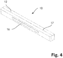
- the Fig. 4 shows a more detailed illustration of an embodiment of a pneumatic cushion 10 which can be used in a vehicle seat 1 according to the invention.
- the pneumatic cushion has a closed cover 12.
- a holding means 16 is arranged on an outer surface of the cover 12, with which the pneumatic cushion 10 can be attached to an edge of a seat surface 2 or a backrest element.
- the holding means 16 is designed as a Velcro strip.
- the sleeve 12 of the pneumatic cushion also has a predetermined folding point 17, which facilitates the folding of the sleeve 12 of the pneumatic cushion 10 during the emptying process.
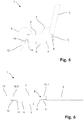
- the Fig. 5 shows a second embodiment of a vehicle seat 1 according to the invention.
- the vehicle seat of this embodiment has a second backrest element in the form of a legrest 13.
- the legrest 13 is connected to a second pivot axis 14 via a second strut 15.
- the legrest 13 can be adjusted in an angle relative to the seat surface 2 in a manner analogous to that of the backrest 3.
- the legrest 13 is at an obtuse angle b to the seat surface 2.
- the second embodiment of the vehicle seat 1 again has a first pneumatic cushion 10.1, which is arranged on an edge of the seat surface 2, which is directed toward the backrest 3.
- a first pneumatic cushion 10.1 By inflating this first pneumatic cushion 10.1, a gap between seat 2 and backrest can be closed.
- a second pneumatic cushion 10.2 is arranged on a further edge of the seat surface 2, which is directed towards the leg support 13, which is inflated during the transition to a lying position in order to fill a gap between the leg support 13 and the seat surface 2.
- a continuous, flat lying surface can be formed with the legrest 13, the seat surface 2 and the backrest 3.
Landscapes
- Engineering & Computer Science (AREA)
- Aviation & Aerospace Engineering (AREA)
- Transportation (AREA)
- Mechanical Engineering (AREA)
- Seats For Vehicles (AREA)
- Chairs For Special Purposes, Such As Reclining Chairs (AREA)
- Chair Legs, Seat Parts, And Backrests (AREA)
Claims (6)
- Siège de véhicule comprenant une surface d'assise (2) ainsi qu'au moins un élément d'appui (3, 13) pivotant autour d'un axe (6) par rapport à la surface d'assise (2), l'au moins un élément d'appui (3, 13) pouvant être déplacé depuis une position d'assise, dans laquelle l'élément d'appui (3, 13) se trouve sensiblement à un angle (a, b) obtus ou concave par rapport à la surface d'assise (2), en une position d'allongement, dans laquelle la surface d'assise (2) ainsi que l'au moins un élément d'appui (3, 13) forment une surface sensiblement plane, et inversement, et le siège de véhicule (1) disposant d'au moins un coussin pneumatique (10 ; 10.1, 10.2) ainsi que d'une unité pneumatique (9), laquelle est configurée de telle sorte que celle-ci gonfle sensiblement entièrement l'au moins un coussin pneumatique (10 ; 10.1, 10.2) lorsque l'au moins un élément d'appui (3, 13) est déplacé dans la position d'allongement, et vide sensiblement entièrement l'au moins un coussin pneumatique (10 ; 10.1, 10.2) lorsque l'au moins un élément d'appui (3, 13) est déplacé dans la position d'assise, caractérisé en ce que l'au moins un coussin pneumatique (10 ; 10.1, 10.2) est disposé dans une zone de bord (8) de la surface d'assise (2) ou de l'au moins un élément d'appui (3, 13), laquelle délimite l'au moins un élément d'appui (3, 13) ou la surface d'assis (2), de sorte que l'au moins un coussin pneumatique (10 ; 10.1, 10.2), dans la position d'allongement, s'étend entre la surface d'assise (2) et l'au moins un élément d'appui (3, 13).
- Siège de véhicule selon la revendication 1, caractérisé en ce que l'au moins un élément d'appui est un dossier (3), un repose-pieds (13) ou les deux.
- Siège de véhicule selon l'une des revendications 1 ou 2, caractérisé en ce que le siège de véhicule (1) dispose d'un actionneur avec lequel l'angle (a) de l'au moins un élément d'appui (3, 13) par rapport à la surface d'assise (2) peut être réglé de manière motorisée, l'unité pneumatique (9) étant configurée de telle sorte que celle-ci gonfle ou vide l'au moins un coussin pneumatique (10 ; 10.1, 10.2) à l'aide de l'état de l'actionneur pneumatique.
- Siège de véhicule selon l'une des revendications 1 à 3, caractérisé en ce que l'unité pneumatique (9) dispose d'une pompe avec laquelle l'au moins un coussin pneumatique (10 ; 10.1, 10.2) se laisse à la fois gonfler et aussi vider.
- Siège de véhicule selon l'une des revendications 1 à 4, caractérisé en ce que l'au moins un coussin pneumatique (10 ; 10.1, 10.2) dispose d'un capteur de pression qui mesure la pression prédominante à l'intérieur de l'au moins un coussin pneumatique (10 ; 10.1, 10.2) et qui est configuré de telle sorte qu'en cas de franchissement vers le haut ou vers le bas d'une pression de consigne prédéfinie, vide ou gonfle l'au moins un coussin pneumatique (10 ; 10.1, 10.2) jusqu'à ce que la pression de consigne soit atteinte.
- Utilisation d'un siège de véhicule selon l'une des revendications 1 à 5 dans un aéronef.
Applications Claiming Priority (2)
| Application Number | Priority Date | Filing Date | Title |
|---|---|---|---|
| CH00433/16A CH712316A1 (de) | 2016-04-04 | 2016-04-04 | Fahrzeugsitz mit mindestens einem pneumatischen Kissen. |
| PCT/EP2016/080308 WO2017174168A1 (fr) | 2016-04-04 | 2016-12-08 | Siège de véhicule muni d'au moins un coussin pneumatique |
Publications (2)
| Publication Number | Publication Date |
|---|---|
| EP3439909A1 EP3439909A1 (fr) | 2019-02-13 |
| EP3439909B1 true EP3439909B1 (fr) | 2020-02-19 |
Family
ID=56068561
Family Applications (1)
| Application Number | Title | Priority Date | Filing Date |
|---|---|---|---|
| EP16808668.4A Active EP3439909B1 (fr) | 2016-04-04 | 2016-12-08 | Siège de véhicule muni d'au moins un coussin pneumatique |
Country Status (6)
| Country | Link |
|---|---|
| US (1) | US10967976B2 (fr) |
| EP (1) | EP3439909B1 (fr) |
| JP (1) | JP2019513614A (fr) |
| CN (1) | CN109070776A (fr) |
| CH (1) | CH712316A1 (fr) |
| WO (1) | WO2017174168A1 (fr) |
Cited By (1)
| Publication number | Priority date | Publication date | Assignee | Title |
|---|---|---|---|---|
| DE102024124003A1 (de) | 2024-08-22 | 2026-02-26 | Audi Aktiengesellschaft | Kraftfahrzeug |
Families Citing this family (4)
| Publication number | Priority date | Publication date | Assignee | Title |
|---|---|---|---|---|
| DE102019204488B4 (de) * | 2019-03-29 | 2023-05-04 | Adient Aerospace, Llc | Sitz, insbesondere Flugzeugsitz |
| US11192653B2 (en) * | 2020-01-21 | 2021-12-07 | B/E Aerospace, Inc. | Pneumatically actuated vehicle seat assemblies |
| NL2029709B1 (nl) * | 2021-11-11 | 2023-06-08 | Automotive Fryslan B V | Slaapbank voor een voertuig |
| CN116901801B (zh) * | 2023-08-09 | 2025-12-30 | 浙江极氪智能科技有限公司 | 汽车座椅和车辆 |
Family Cites Families (23)
| Publication number | Priority date | Publication date | Assignee | Title |
|---|---|---|---|---|
| US4629248A (en) * | 1985-06-03 | 1986-12-16 | General Motors Corporation | Thigh support for vehicle seats |
| DE3631872C1 (de) * | 1986-09-19 | 1987-10-01 | Daimler Benz Ag | Fahrzeugsitz |
| US5370444A (en) * | 1992-09-11 | 1994-12-06 | Sears Manufacturing Company | Adjustable cushion |
| JPH0747016A (ja) * | 1993-08-05 | 1995-02-21 | Nissan Motor Co Ltd | 座席装置 |
| DE4431573A1 (de) * | 1994-09-05 | 1995-03-30 | Gian Hung Chang | Fahrzeugsitz |
| US5788329A (en) * | 1996-02-08 | 1998-08-04 | Pilarczyk; Ervin Robert | Fold-down seat for a motor vehicle |
| US5975636A (en) * | 1997-08-12 | 1999-11-02 | Koch; Roger | Assembly for filling void between cushions of reclining seats |
| FR2776586B1 (fr) * | 1998-03-30 | 2000-06-09 | Adder Sa | Dispositif de conversion de sieges en couchettes, siege destine a un tel dispositif et moyen de transport ainsi equipe |
| GB9918263D0 (en) * | 1999-08-04 | 1999-10-06 | Britax Rumbold Ltd | Seating unit of a passenger vehicle |
| CA2581738C (fr) * | 2001-08-09 | 2009-04-14 | Virgin Atlantic Airways Limited | Systeme de sieges et unite d'accueil de passagers pour vehicule |
| FR2840282B1 (fr) * | 2002-05-31 | 2004-07-30 | Sicma Aero Seat | Siege transformable en couchette a accoudoir deformable |
| US20080100109A1 (en) * | 2006-10-11 | 2008-05-01 | Neil Michael Frank | Integrated child car seat |
| CA2750767C (fr) * | 2009-01-30 | 2018-04-10 | Air New Zealand Limited | Agencement d'assise, ensemble siege, tablette et systeme d'assise |
| GB0903744D0 (en) * | 2009-03-04 | 2009-04-15 | Virgin Atlantic Airways Ltd | A seating insallation for a passenger vehicle |
| DE102010020642A1 (de) | 2010-05-15 | 2011-11-17 | Dornier Technologie Gmbh & Co. Kg | Pneumatiksteuerung für Fahrzeugsitz, insbesondere Fluggastsitz |
| US20130256072A1 (en) * | 2012-04-02 | 2013-10-03 | Modrek Farhat | Luggage Having A Folded Bed |
| US9039085B2 (en) * | 2012-06-04 | 2015-05-26 | Ford Global Technologies, Llc | Seat extension seamless gap fill |
| US9228885B2 (en) * | 2012-06-21 | 2016-01-05 | Hill-Rom Services, Inc. | Patient support systems and methods of use |
| US9090185B2 (en) * | 2013-03-14 | 2015-07-28 | Leggett & Platt Canada Co. | Seat with pneumatic headrest and thigh adjustment |
| WO2015073363A1 (fr) | 2013-11-12 | 2015-05-21 | B/E Aerospace, Inc. | Siège d'avion comportant une capacité de position couchée à plat pour le taxi, le décollage et l'atterrissage |
| EP2944510A1 (fr) | 2014-05-14 | 2015-11-18 | Lantal Textiles AG | Siège de véhicule doté d'une surface d'assise réglable |
| EP2944509B1 (fr) | 2014-05-14 | 2017-12-20 | Lantal Textiles AG | Siège de véhicule doté d'un dossier mobile |
| US9527417B2 (en) * | 2015-02-17 | 2016-12-27 | Ford Global Technologies, Llc | Air-suspended seat surfaces for folding vehicle seats |
-
2016
- 2016-04-04 CH CH00433/16A patent/CH712316A1/de unknown
- 2016-12-08 JP JP2018552044A patent/JP2019513614A/ja active Pending
- 2016-12-08 US US16/090,854 patent/US10967976B2/en active Active
- 2016-12-08 WO PCT/EP2016/080308 patent/WO2017174168A1/fr not_active Ceased
- 2016-12-08 CN CN201680084261.3A patent/CN109070776A/zh active Pending
- 2016-12-08 EP EP16808668.4A patent/EP3439909B1/fr active Active
Non-Patent Citations (1)
| Title |
|---|
| None * |
Cited By (1)
| Publication number | Priority date | Publication date | Assignee | Title |
|---|---|---|---|---|
| DE102024124003A1 (de) | 2024-08-22 | 2026-02-26 | Audi Aktiengesellschaft | Kraftfahrzeug |
Also Published As
| Publication number | Publication date |
|---|---|
| CN109070776A (zh) | 2018-12-21 |
| CH712316A1 (de) | 2017-10-13 |
| EP3439909A1 (fr) | 2019-02-13 |
| WO2017174168A1 (fr) | 2017-10-12 |
| US10967976B2 (en) | 2021-04-06 |
| JP2019513614A (ja) | 2019-05-30 |
| US20190106214A1 (en) | 2019-04-11 |
Similar Documents
| Publication | Publication Date | Title |
|---|---|---|
| EP3439909B1 (fr) | Siège de véhicule muni d'au moins un coussin pneumatique | |
| DE102016104908B4 (de) | Mehrschichtiger Sitz | |
| EP3142892B1 (fr) | Siège de véhicule doté d'une surface d'assise réglable et une methode de regler une surface d'assise | |
| EP2944509B1 (fr) | Siège de véhicule doté d'un dossier mobile | |
| EP2414191B1 (fr) | Siège avec un élément de garnissage et méthode d'adaption du contour du siège | |
| DE102007007116B4 (de) | Fahrzeugsitzanordnung mit beweglichen Polstern | |
| DE102009048734A1 (de) | Sitzpolster mit Blasenelementen | |
| DE102013207858A1 (de) | Autositz mit einstellbarer festigkeit | |
| DE102012208725A1 (de) | Rückenlehne für einen Fahrzeugsitz | |
| DE102008028353A1 (de) | Fahrzeugsitz | |
| AT502779A1 (de) | System zur automatischen verstellung der sitz-kontur sowie sitz, insbesonders fahrzeugsitz für automobile, flugzeuge oder dergleichen | |
| DE102010021067A1 (de) | Fahrzeugsitz mit formveränderlichen Seitenwangen | |
| EP3693274B1 (fr) | Système de massage dans siège d'avion et siège d'avion doté d'un système de massage | |
| DE102016221508A1 (de) | Verstellbarer Fahrzeugsitz | |
| DE102018118157A1 (de) | Aktive einstellung eines sitzpolsters auf grundlage eines druckkennfelds für einen insassen und verfahren | |
| EP2719622A2 (fr) | Siège d'avion | |
| DE202018105787U1 (de) | Auslassleitung für aufpumpbare Sitze | |
| CH711796A1 (de) | Pneumatisches Kissen mit Pumpeneinheit. | |
| DE102016202089A1 (de) | Fahrzeug, insbesondere Schienenfahrzeug, mit zumindest einem Sitz | |
| DE102016224885B4 (de) | Fahrzeugsitz und Verfahren zur individuellen Anpassung seiner Sitz- und/oder Lehnflächenkontur an einen Sitzbenutzer | |
| EP4308415B1 (fr) | Ensemble d'ajustement pour ajuster au moins une région de contour de siège d'un siège de véhicule pour un véhicule, siège de véhicule ayant l'ensemble d'ajustement, et véhicule ayant le siège de véhicule | |
| DE102019132647B4 (de) | Fahrzeugsitz mit einer Kopfstütze mit entfaltbarem Kissen | |
| DE102016007491B4 (de) | Fahrzeugsitz und Kraftfahrzeug umfassend einen Fahrzeugsitz | |
| EP1724193A1 (fr) | Siège passager | |
| EP2944570A1 (fr) | Couchette destinée à être utilisée dans un avion |
Legal Events
| Date | Code | Title | Description |
|---|---|---|---|
| STAA | Information on the status of an ep patent application or granted ep patent |
Free format text: STATUS: UNKNOWN |
|
| STAA | Information on the status of an ep patent application or granted ep patent |
Free format text: STATUS: THE INTERNATIONAL PUBLICATION HAS BEEN MADE |
|
| PUAI | Public reference made under article 153(3) epc to a published international application that has entered the european phase |
Free format text: ORIGINAL CODE: 0009012 |
|
| STAA | Information on the status of an ep patent application or granted ep patent |
Free format text: STATUS: REQUEST FOR EXAMINATION WAS MADE |
|
| 17P | Request for examination filed |
Effective date: 20180724 |
|
| AK | Designated contracting states |
Kind code of ref document: A1 Designated state(s): AL AT BE BG CH CY CZ DE DK EE ES FI FR GB GR HR HU IE IS IT LI LT LU LV MC MK MT NL NO PL PT RO RS SE SI SK SM TR |
|
| AX | Request for extension of the european patent |
Extension state: BA ME |
|
| DAV | Request for validation of the european patent (deleted) | ||
| DAX | Request for extension of the european patent (deleted) | ||
| RIC1 | Information provided on ipc code assigned before grant |
Ipc: B60N 2/90 20180101ALI20190716BHEP Ipc: B60N 2/34 20060101AFI20190716BHEP |
|
| GRAJ | Information related to disapproval of communication of intention to grant by the applicant or resumption of examination proceedings by the epo deleted |
Free format text: ORIGINAL CODE: EPIDOSDIGR1 |
|
| GRAP | Despatch of communication of intention to grant a patent |
Free format text: ORIGINAL CODE: EPIDOSNIGR1 |
|
| GRAP | Despatch of communication of intention to grant a patent |
Free format text: ORIGINAL CODE: EPIDOSNIGR1 |
|
| STAA | Information on the status of an ep patent application or granted ep patent |
Free format text: STATUS: GRANT OF PATENT IS INTENDED |
|
| INTG | Intention to grant announced |
Effective date: 20191108 |
|
| INTC | Intention to grant announced (deleted) | ||
| INTG | Intention to grant announced |
Effective date: 20191119 |
|
| GRAS | Grant fee paid |
Free format text: ORIGINAL CODE: EPIDOSNIGR3 |
|
| GRAA | (expected) grant |
Free format text: ORIGINAL CODE: 0009210 |
|
| STAA | Information on the status of an ep patent application or granted ep patent |
Free format text: STATUS: THE PATENT HAS BEEN GRANTED |
|
| AK | Designated contracting states |
Kind code of ref document: B1 Designated state(s): AL AT BE BG CH CY CZ DE DK EE ES FI FR GB GR HR HU IE IS IT LI LT LU LV MC MK MT NL NO PL PT RO RS SE SI SK SM TR |
|
| REG | Reference to a national code |
Ref country code: CH Ref legal event code: NV Representative=s name: KELLER AND PARTNER PATENTANWAELTE AG, CH Ref country code: CH Ref legal event code: EP |
|
| REG | Reference to a national code |
Ref country code: DE Ref legal event code: R096 Ref document number: 502016008853 Country of ref document: DE |
|
| REG | Reference to a national code |
Ref country code: AT Ref legal event code: REF Ref document number: 1234571 Country of ref document: AT Kind code of ref document: T Effective date: 20200315 |
|
| REG | Reference to a national code |
Ref country code: IE Ref legal event code: FG4D Free format text: LANGUAGE OF EP DOCUMENT: GERMAN |
|
| REG | Reference to a national code |
Ref country code: NL Ref legal event code: MP Effective date: 20200219 |
|
| PG25 | Lapsed in a contracting state [announced via postgrant information from national office to epo] |
Ref country code: FI Free format text: LAPSE BECAUSE OF FAILURE TO SUBMIT A TRANSLATION OF THE DESCRIPTION OR TO PAY THE FEE WITHIN THE PRESCRIBED TIME-LIMIT Effective date: 20200219 Ref country code: RS Free format text: LAPSE BECAUSE OF FAILURE TO SUBMIT A TRANSLATION OF THE DESCRIPTION OR TO PAY THE FEE WITHIN THE PRESCRIBED TIME-LIMIT Effective date: 20200219 Ref country code: NO Free format text: LAPSE BECAUSE OF FAILURE TO SUBMIT A TRANSLATION OF THE DESCRIPTION OR TO PAY THE FEE WITHIN THE PRESCRIBED TIME-LIMIT Effective date: 20200519 |
|
| REG | Reference to a national code |
Ref country code: LT Ref legal event code: MG4D |
|
| PG25 | Lapsed in a contracting state [announced via postgrant information from national office to epo] |
Ref country code: BG Free format text: LAPSE BECAUSE OF FAILURE TO SUBMIT A TRANSLATION OF THE DESCRIPTION OR TO PAY THE FEE WITHIN THE PRESCRIBED TIME-LIMIT Effective date: 20200519 Ref country code: IS Free format text: LAPSE BECAUSE OF FAILURE TO SUBMIT A TRANSLATION OF THE DESCRIPTION OR TO PAY THE FEE WITHIN THE PRESCRIBED TIME-LIMIT Effective date: 20200619 Ref country code: SE Free format text: LAPSE BECAUSE OF FAILURE TO SUBMIT A TRANSLATION OF THE DESCRIPTION OR TO PAY THE FEE WITHIN THE PRESCRIBED TIME-LIMIT Effective date: 20200219 Ref country code: LV Free format text: LAPSE BECAUSE OF FAILURE TO SUBMIT A TRANSLATION OF THE DESCRIPTION OR TO PAY THE FEE WITHIN THE PRESCRIBED TIME-LIMIT Effective date: 20200219 Ref country code: GR Free format text: LAPSE BECAUSE OF FAILURE TO SUBMIT A TRANSLATION OF THE DESCRIPTION OR TO PAY THE FEE WITHIN THE PRESCRIBED TIME-LIMIT Effective date: 20200520 Ref country code: HR Free format text: LAPSE BECAUSE OF FAILURE TO SUBMIT A TRANSLATION OF THE DESCRIPTION OR TO PAY THE FEE WITHIN THE PRESCRIBED TIME-LIMIT Effective date: 20200219 |
|
| PG25 | Lapsed in a contracting state [announced via postgrant information from national office to epo] |
Ref country code: NL Free format text: LAPSE BECAUSE OF FAILURE TO SUBMIT A TRANSLATION OF THE DESCRIPTION OR TO PAY THE FEE WITHIN THE PRESCRIBED TIME-LIMIT Effective date: 20200219 |
|
| REG | Reference to a national code |
Ref country code: CH Ref legal event code: PFA Owner name: LANTAL TEXTILES AG, CH Free format text: FORMER OWNER: LANTAL TEXTILES AG, CH |
|
| PG25 | Lapsed in a contracting state [announced via postgrant information from national office to epo] |
Ref country code: SK Free format text: LAPSE BECAUSE OF FAILURE TO SUBMIT A TRANSLATION OF THE DESCRIPTION OR TO PAY THE FEE WITHIN THE PRESCRIBED TIME-LIMIT Effective date: 20200219 Ref country code: DK Free format text: LAPSE BECAUSE OF FAILURE TO SUBMIT A TRANSLATION OF THE DESCRIPTION OR TO PAY THE FEE WITHIN THE PRESCRIBED TIME-LIMIT Effective date: 20200219 Ref country code: PT Free format text: LAPSE BECAUSE OF FAILURE TO SUBMIT A TRANSLATION OF THE DESCRIPTION OR TO PAY THE FEE WITHIN THE PRESCRIBED TIME-LIMIT Effective date: 20200712 Ref country code: LT Free format text: LAPSE BECAUSE OF FAILURE TO SUBMIT A TRANSLATION OF THE DESCRIPTION OR TO PAY THE FEE WITHIN THE PRESCRIBED TIME-LIMIT Effective date: 20200219 Ref country code: SM Free format text: LAPSE BECAUSE OF FAILURE TO SUBMIT A TRANSLATION OF THE DESCRIPTION OR TO PAY THE FEE WITHIN THE PRESCRIBED TIME-LIMIT Effective date: 20200219 Ref country code: EE Free format text: LAPSE BECAUSE OF FAILURE TO SUBMIT A TRANSLATION OF THE DESCRIPTION OR TO PAY THE FEE WITHIN THE PRESCRIBED TIME-LIMIT Effective date: 20200219 Ref country code: CZ Free format text: LAPSE BECAUSE OF FAILURE TO SUBMIT A TRANSLATION OF THE DESCRIPTION OR TO PAY THE FEE WITHIN THE PRESCRIBED TIME-LIMIT Effective date: 20200219 Ref country code: RO Free format text: LAPSE BECAUSE OF FAILURE TO SUBMIT A TRANSLATION OF THE DESCRIPTION OR TO PAY THE FEE WITHIN THE PRESCRIBED TIME-LIMIT Effective date: 20200219 Ref country code: ES Free format text: LAPSE BECAUSE OF FAILURE TO SUBMIT A TRANSLATION OF THE DESCRIPTION OR TO PAY THE FEE WITHIN THE PRESCRIBED TIME-LIMIT Effective date: 20200219 |
|
| REG | Reference to a national code |
Ref country code: DE Ref legal event code: R097 Ref document number: 502016008853 Country of ref document: DE |
|
| PLBE | No opposition filed within time limit |
Free format text: ORIGINAL CODE: 0009261 |
|
| STAA | Information on the status of an ep patent application or granted ep patent |
Free format text: STATUS: NO OPPOSITION FILED WITHIN TIME LIMIT |
|
| 26N | No opposition filed |
Effective date: 20201120 |
|
| PG25 | Lapsed in a contracting state [announced via postgrant information from national office to epo] |
Ref country code: SI Free format text: LAPSE BECAUSE OF FAILURE TO SUBMIT A TRANSLATION OF THE DESCRIPTION OR TO PAY THE FEE WITHIN THE PRESCRIBED TIME-LIMIT Effective date: 20200219 Ref country code: PL Free format text: LAPSE BECAUSE OF FAILURE TO SUBMIT A TRANSLATION OF THE DESCRIPTION OR TO PAY THE FEE WITHIN THE PRESCRIBED TIME-LIMIT Effective date: 20200219 |
|
| PG25 | Lapsed in a contracting state [announced via postgrant information from national office to epo] |
Ref country code: MC Free format text: LAPSE BECAUSE OF FAILURE TO SUBMIT A TRANSLATION OF THE DESCRIPTION OR TO PAY THE FEE WITHIN THE PRESCRIBED TIME-LIMIT Effective date: 20200219 |
|
| REG | Reference to a national code |
Ref country code: BE Ref legal event code: MM Effective date: 20201231 |
|
| PG25 | Lapsed in a contracting state [announced via postgrant information from national office to epo] |
Ref country code: LU Free format text: LAPSE BECAUSE OF NON-PAYMENT OF DUE FEES Effective date: 20201208 |
|
| PG25 | Lapsed in a contracting state [announced via postgrant information from national office to epo] |
Ref country code: TR Free format text: LAPSE BECAUSE OF FAILURE TO SUBMIT A TRANSLATION OF THE DESCRIPTION OR TO PAY THE FEE WITHIN THE PRESCRIBED TIME-LIMIT Effective date: 20200219 Ref country code: MT Free format text: LAPSE BECAUSE OF FAILURE TO SUBMIT A TRANSLATION OF THE DESCRIPTION OR TO PAY THE FEE WITHIN THE PRESCRIBED TIME-LIMIT Effective date: 20200219 Ref country code: CY Free format text: LAPSE BECAUSE OF FAILURE TO SUBMIT A TRANSLATION OF THE DESCRIPTION OR TO PAY THE FEE WITHIN THE PRESCRIBED TIME-LIMIT Effective date: 20200219 |
|
| PG25 | Lapsed in a contracting state [announced via postgrant information from national office to epo] |
Ref country code: MK Free format text: LAPSE BECAUSE OF FAILURE TO SUBMIT A TRANSLATION OF THE DESCRIPTION OR TO PAY THE FEE WITHIN THE PRESCRIBED TIME-LIMIT Effective date: 20200219 Ref country code: AL Free format text: LAPSE BECAUSE OF FAILURE TO SUBMIT A TRANSLATION OF THE DESCRIPTION OR TO PAY THE FEE WITHIN THE PRESCRIBED TIME-LIMIT Effective date: 20200219 |
|
| PG25 | Lapsed in a contracting state [announced via postgrant information from national office to epo] |
Ref country code: BE Free format text: LAPSE BECAUSE OF NON-PAYMENT OF DUE FEES Effective date: 20201231 |
|
| REG | Reference to a national code |
Ref country code: AT Ref legal event code: MM01 Ref document number: 1234571 Country of ref document: AT Kind code of ref document: T Effective date: 20211208 |
|
| PG25 | Lapsed in a contracting state [announced via postgrant information from national office to epo] |
Ref country code: AT Free format text: LAPSE BECAUSE OF NON-PAYMENT OF DUE FEES Effective date: 20211208 |
|
| REG | Reference to a national code |
Ref country code: CH Ref legal event code: U11 Free format text: ST27 STATUS EVENT CODE: U-0-0-U10-U11 (AS PROVIDED BY THE NATIONAL OFFICE) Effective date: 20260101 |
|
| PGFP | Annual fee paid to national office [announced via postgrant information from national office to epo] |
Ref country code: DE Payment date: 20251211 Year of fee payment: 10 |
|
| PGFP | Annual fee paid to national office [announced via postgrant information from national office to epo] |
Ref country code: GB Payment date: 20251219 Year of fee payment: 10 |
|
| PGFP | Annual fee paid to national office [announced via postgrant information from national office to epo] |
Ref country code: IT Payment date: 20251223 Year of fee payment: 10 |
|
| PGFP | Annual fee paid to national office [announced via postgrant information from national office to epo] |
Ref country code: FR Payment date: 20251229 Year of fee payment: 10 |
|
| PGFP | Annual fee paid to national office [announced via postgrant information from national office to epo] |
Ref country code: IE Payment date: 20251219 Year of fee payment: 10 |
|
| PGFP | Annual fee paid to national office [announced via postgrant information from national office to epo] |
Ref country code: CH Payment date: 20260101 Year of fee payment: 10 |