EP3439971B1 - Procédé et dispositif permettant de former des corps d'emballage ouverts d'un côté à partir d'enveloppes d'emballage ouvertes des deux côtés - Google Patents
Procédé et dispositif permettant de former des corps d'emballage ouverts d'un côté à partir d'enveloppes d'emballage ouvertes des deux côtés Download PDFInfo
- Publication number
- EP3439971B1 EP3439971B1 EP17716150.2A EP17716150A EP3439971B1 EP 3439971 B1 EP3439971 B1 EP 3439971B1 EP 17716150 A EP17716150 A EP 17716150A EP 3439971 B1 EP3439971 B1 EP 3439971B1
- Authority
- EP
- European Patent Office
- Prior art keywords
- package
- sleeve
- sleeves
- mandrel
- jacket
- Prior art date
- Legal status (The legal status is an assumption and is not a legal conclusion. Google has not performed a legal analysis and makes no representation as to the accuracy of the status listed.)
- Active
Links
Images


Classifications
-
- B—PERFORMING OPERATIONS; TRANSPORTING
- B65—CONVEYING; PACKING; STORING; HANDLING THIN OR FILAMENTARY MATERIAL
- B65B—MACHINES, APPARATUS OR DEVICES FOR, OR METHODS OF, PACKAGING ARTICLES OR MATERIALS; UNPACKING
- B65B3/00—Packaging plastic material, semiliquids, liquids or mixed solids and liquids, in individual containers or receptacles, e.g. bags, sacks, boxes, cartons, cans, or jars
- B65B3/02—Machines characterised by the incorporation of means for making the containers or receptacles
- B65B3/025—Making parallelepipedal containers from a single carton blank
-
- B—PERFORMING OPERATIONS; TRANSPORTING
- B31—MAKING ARTICLES OF PAPER, CARDBOARD OR MATERIAL WORKED IN A MANNER ANALOGOUS TO PAPER; WORKING PAPER, CARDBOARD OR MATERIAL WORKED IN A MANNER ANALOGOUS TO PAPER
- B31B—MAKING CONTAINERS OF PAPER, CARDBOARD OR MATERIAL WORKED IN A MANNER ANALOGOUS TO PAPER
- B31B50/00—Making rigid or semi-rigid containers, e.g. boxes or cartons
- B31B50/006—Controlling; Regulating; Measuring; Improving safety
-
- B—PERFORMING OPERATIONS; TRANSPORTING
- B31—MAKING ARTICLES OF PAPER, CARDBOARD OR MATERIAL WORKED IN A MANNER ANALOGOUS TO PAPER; WORKING PAPER, CARDBOARD OR MATERIAL WORKED IN A MANNER ANALOGOUS TO PAPER
- B31B—MAKING CONTAINERS OF PAPER, CARDBOARD OR MATERIAL WORKED IN A MANNER ANALOGOUS TO PAPER
- B31B50/00—Making rigid or semi-rigid containers, e.g. boxes or cartons
- B31B50/26—Folding sheets, blanks or webs
- B31B50/28—Folding sheets, blanks or webs around mandrels, e.g. for forming bottoms
- B31B50/30—Folding sheets, blanks or webs around mandrels, e.g. for forming bottoms the mandrels moving
- B31B50/32—Folding sheets, blanks or webs around mandrels, e.g. for forming bottoms the mandrels moving in circular paths
- B31B50/322—Folding sheets, blanks or webs around mandrels, e.g. for forming bottoms the mandrels moving in circular paths the mandrels extending radially from the periphery of a drum
-
- B—PERFORMING OPERATIONS; TRANSPORTING
- B31—MAKING ARTICLES OF PAPER, CARDBOARD OR MATERIAL WORKED IN A MANNER ANALOGOUS TO PAPER; WORKING PAPER, CARDBOARD OR MATERIAL WORKED IN A MANNER ANALOGOUS TO PAPER
- B31B—MAKING CONTAINERS OF PAPER, CARDBOARD OR MATERIAL WORKED IN A MANNER ANALOGOUS TO PAPER
- B31B50/00—Making rigid or semi-rigid containers, e.g. boxes or cartons
- B31B50/74—Auxiliary operations
- B31B50/76—Opening and distending flattened articles
- B31B50/78—Mechanically
- B31B50/782—Mechanically by pushing the opposite ends of collapsed blanks towards each other
-
- B—PERFORMING OPERATIONS; TRANSPORTING
- B31—MAKING ARTICLES OF PAPER, CARDBOARD OR MATERIAL WORKED IN A MANNER ANALOGOUS TO PAPER; WORKING PAPER, CARDBOARD OR MATERIAL WORKED IN A MANNER ANALOGOUS TO PAPER
- B31B—MAKING CONTAINERS OF PAPER, CARDBOARD OR MATERIAL WORKED IN A MANNER ANALOGOUS TO PAPER
- B31B50/00—Making rigid or semi-rigid containers, e.g. boxes or cartons
- B31B50/74—Auxiliary operations
- B31B50/76—Opening and distending flattened articles
- B31B50/78—Mechanically
- B31B50/788—Mechanically by introducing the blanks into undeformable holders, e.g. on a drum or on chains
-
- B—PERFORMING OPERATIONS; TRANSPORTING
- B65—CONVEYING; PACKING; STORING; HANDLING THIN OR FILAMENTARY MATERIAL
- B65B—MACHINES, APPARATUS OR DEVICES FOR, OR METHODS OF, PACKAGING ARTICLES OR MATERIALS; UNPACKING
- B65B41/00—Supplying or feeding container-forming sheets or wrapping material
- B65B41/02—Feeding sheets or wrapper blanks
- B65B41/04—Feeding sheets or wrapper blanks by grippers
- B65B41/06—Feeding sheets or wrapper blanks by grippers by suction-operated grippers
-
- B—PERFORMING OPERATIONS; TRANSPORTING
- B65—CONVEYING; PACKING; STORING; HANDLING THIN OR FILAMENTARY MATERIAL
- B65B—MACHINES, APPARATUS OR DEVICES FOR, OR METHODS OF, PACKAGING ARTICLES OR MATERIALS; UNPACKING
- B65B43/00—Forming, feeding, opening or setting-up containers or receptacles in association with packaging
- B65B43/12—Feeding flexible bags or carton blanks in flat or collapsed state; Feeding flat bags connected to form a series or chain
- B65B43/14—Feeding individual bags or carton blanks from piles or magazines
- B65B43/145—Feeding carton blanks from piles or magazines
-
- B—PERFORMING OPERATIONS; TRANSPORTING
- B65—CONVEYING; PACKING; STORING; HANDLING THIN OR FILAMENTARY MATERIAL
- B65B—MACHINES, APPARATUS OR DEVICES FOR, OR METHODS OF, PACKAGING ARTICLES OR MATERIALS; UNPACKING
- B65B43/00—Forming, feeding, opening or setting-up containers or receptacles in association with packaging
- B65B43/26—Opening or distending bags; Opening, erecting, or setting-up boxes, cartons, or carton blanks
- B65B43/32—Opening or distending bags; Opening, erecting, or setting-up boxes, cartons, or carton blanks by external pressure diagonally applied
- B65B43/325—Opening or distending bags; Opening, erecting, or setting-up boxes, cartons, or carton blanks by external pressure diagonally applied to boxes, cartons or carton blanks
-
- B—PERFORMING OPERATIONS; TRANSPORTING
- B65—CONVEYING; PACKING; STORING; HANDLING THIN OR FILAMENTARY MATERIAL
- B65B—MACHINES, APPARATUS OR DEVICES FOR, OR METHODS OF, PACKAGING ARTICLES OR MATERIALS; UNPACKING
- B65B43/00—Forming, feeding, opening or setting-up containers or receptacles in association with packaging
- B65B43/42—Feeding or positioning bags, boxes, or cartons in the distended, opened, or set-up state; Feeding preformed rigid containers, e.g. tins, capsules, glass tubes, glasses, to the packaging position; Locating containers or receptacles at the filling position; Supporting containers or receptacles during the filling operation
- B65B43/50—Feeding or positioning bags, boxes, or cartons in the distended, opened, or set-up state; Feeding preformed rigid containers, e.g. tins, capsules, glass tubes, glasses, to the packaging position; Locating containers or receptacles at the filling position; Supporting containers or receptacles during the filling operation using rotary tables or turrets
-
- B—PERFORMING OPERATIONS; TRANSPORTING
- B65—CONVEYING; PACKING; STORING; HANDLING THIN OR FILAMENTARY MATERIAL
- B65B—MACHINES, APPARATUS OR DEVICES FOR, OR METHODS OF, PACKAGING ARTICLES OR MATERIALS; UNPACKING
- B65B43/00—Forming, feeding, opening or setting-up containers or receptacles in association with packaging
- B65B43/42—Feeding or positioning bags, boxes, or cartons in the distended, opened, or set-up state; Feeding preformed rigid containers, e.g. tins, capsules, glass tubes, glasses, to the packaging position; Locating containers or receptacles at the filling position; Supporting containers or receptacles during the filling operation
- B65B43/54—Means for supporting containers or receptacles during the filling operation
-
- B—PERFORMING OPERATIONS; TRANSPORTING
- B65—CONVEYING; PACKING; STORING; HANDLING THIN OR FILAMENTARY MATERIAL
- B65B—MACHINES, APPARATUS OR DEVICES FOR, OR METHODS OF, PACKAGING ARTICLES OR MATERIALS; UNPACKING
- B65B55/00—Preserving, protecting or purifying packages or package contents in association with packaging
- B65B55/02—Sterilising, e.g. of complete packages
- B65B55/04—Sterilising wrappers or receptacles prior to, or during, packaging
- B65B55/10—Sterilising wrappers or receptacles prior to, or during, packaging by liquids or gases
-
- B—PERFORMING OPERATIONS; TRANSPORTING
- B65—CONVEYING; PACKING; STORING; HANDLING THIN OR FILAMENTARY MATERIAL
- B65B—MACHINES, APPARATUS OR DEVICES FOR, OR METHODS OF, PACKAGING ARTICLES OR MATERIALS; UNPACKING
- B65B61/00—Auxiliary devices, not otherwise provided for, for operating on sheets, blanks, webs, binding material, containers or packages
- B65B61/24—Auxiliary devices, not otherwise provided for, for operating on sheets, blanks, webs, binding material, containers or packages for shaping or reshaping completed packages
-
- B—PERFORMING OPERATIONS; TRANSPORTING
- B65—CONVEYING; PACKING; STORING; HANDLING THIN OR FILAMENTARY MATERIAL
- B65B—MACHINES, APPARATUS OR DEVICES FOR, OR METHODS OF, PACKAGING ARTICLES OR MATERIALS; UNPACKING
- B65B7/00—Closing containers or receptacles after filling
- B65B7/16—Closing semi-rigid or rigid containers or receptacles not deformed by, or not taking-up shape of, contents, e.g. boxes or cartons
-
- B—PERFORMING OPERATIONS; TRANSPORTING
- B31—MAKING ARTICLES OF PAPER, CARDBOARD OR MATERIAL WORKED IN A MANNER ANALOGOUS TO PAPER; WORKING PAPER, CARDBOARD OR MATERIAL WORKED IN A MANNER ANALOGOUS TO PAPER
- B31B—MAKING CONTAINERS OF PAPER, CARDBOARD OR MATERIAL WORKED IN A MANNER ANALOGOUS TO PAPER
- B31B2100/00—Rigid or semi-rigid containers made by folding single-piece sheets, blanks or webs
- B31B2100/002—Rigid or semi-rigid containers made by folding single-piece sheets, blanks or webs characterised by the shape of the blank from which they are formed
- B31B2100/0022—Rigid or semi-rigid containers made by folding single-piece sheets, blanks or webs characterised by the shape of the blank from which they are formed made from tubular webs or blanks, including by tube or bottom forming operations
-
- B—PERFORMING OPERATIONS; TRANSPORTING
- B31—MAKING ARTICLES OF PAPER, CARDBOARD OR MATERIAL WORKED IN A MANNER ANALOGOUS TO PAPER; WORKING PAPER, CARDBOARD OR MATERIAL WORKED IN A MANNER ANALOGOUS TO PAPER
- B31B—MAKING CONTAINERS OF PAPER, CARDBOARD OR MATERIAL WORKED IN A MANNER ANALOGOUS TO PAPER
- B31B2105/00—Rigid or semi-rigid containers made by assembling separate sheets, blanks or webs
- B31B2105/002—Making boxes characterised by the shape of the blanks from which they are formed
- B31B2105/0022—Making boxes from tubular webs or blanks, e.g. with separate bottoms, including tube or bottom forming operations
Definitions
- the invention relates to a method for forming packaging bodies which are open on one side from packaging casings which are open on both sides for the production of filled packs.
- the invention further relates to a device for forming packaging bodies which are open on one side from packaging casings which are open on both sides for the production of filled packs according to the preamble of claim 10.
- Methods and devices for forming packaging bodies that are open on one side from packaging casings that are open on both sides have been known for some time.
- the methods are used, in particular, to produce filled packs, and processes and devices for filling packs with products in different configurations are also known.
- package bodies are understood to mean containers such as, for example, composite cardboard packaging, which are at least partially formed from a packaging material in the form of a laminate comprising a cardboard layer and outer, in particular thermoplastic, plastic layers, for example of polyethylene (PE).
- the carton gives the packs sufficient stability so that the packs can be handled easily and, for example, stacked.
- the plastic layers protect the cardboard from moisture and the food from the absorption of unwanted substances from the pack.
- Corresponding packing bodies are typically filled with products in the form of foodstuffs, in particular beverages, the flow products being predominantly products.
- the packing bodies are filled with food in a sterile or aseptic environment of a filling machine, since the food should be kept for a long time after the packs have been filled.
- the filling machines have, for example, sterilization rooms or aseptic chambers in which the packing bodies are sterilized and then filled and sealed under as sterile conditions as possible. After the packing bodies have been filled, they are typically sealed in the filling machine. When using appropriate packaging materials, the package body is closed by sealing the open end.
- the packing bodies are preferably formed on the filling machine from packing sleeves, which in turn are made from packaging blanks, in particular by sealing the longitudinal edges of the packaging blanks to one another.
- the inner longitudinal edge can be folded outwards in order to prevent moisture from penetrating into the packaging material, in particular the carton.
- packaging shells are made from a packaging material that are open at the opposite longitudinal ends.
- the pack sleeves are pre-folded along four fold lines running longitudinally to the pack sleeve, creating fold edges which form the later edges of the pack, which typically forms a square or rectangular cross section. First, however, the packaging sleeves are folded flat around two opposite folding edges. Two of the pre-folded fold lines are folded back.
- the packing jacket then essentially forms two sections running parallel to one another and lying one on top of the other.
- the flat-folded packaging sleeves are transferred as a stack to a magazine on the filling machine.
- the front section of the packaging jacket at the front end of the stack is gripped by suction cups and away from the stack pulled, the packing jacket unfolding, typically until an at least substantially square or rectangular cross section is formed.
- the unfolding takes place along the pre-folded folding lines, two of which have formed the folding edges of the folded-up packaging jacket, since the packaging material can be easily folded or folded along the, in particular pre-folded, folding lines.
- the correspondingly unfolded packing jacket is then pulled onto a mandrel of a so-called mandrel wheel, the cross section of the mandrel corresponding to the cross section of the packing jacket.
- the packing jacket protrudes outward beyond the mandrel so that the protruding part of the packing jacket can be folded against the end face of the mandrel and pressed and sealed there.
- the corresponding longitudinal end of the packaging jacket is closed and regularly forms the bottom of the later filled package. Alternatively, the closed end of the package jacket could also form the head of the later package if it is filled through the open bottom, for example.
- the packaging bodies which are open on one side, are introduced into a sterilization zone of the filling machine. This is usually done by successively transferring the package bodies to the cells of a transport device that receive the package bodies. The transport device then ensures that the package bodies are transported through the sterilization zone of the filling machine at a defined speed and at a defined distance from one another. In the sterilization zone, the package bodies are preheated with hot sterile air and then sterilized, typically with hydrogen peroxide, and dried with sterile air. The sterile packing bodies are transferred to the filling and sealing zone and filled there. The opening of the filled packing bodies is then closed before the closed packing is transported out of the filling and sealing zone via the transport device and is then removed from the corresponding cells of the transport device.
- the packing bodies are transported by the transport device in a straight line through the filling machine.
- Corresponding filling machines are also called cross-country skiers.
- the so-called rotary machines the packing bodies describe a more or less arc-shaped movement, which can comprise one or more circular arc sections.
- the present invention basically relates to both types of filling machines.
- the method and the device of the type described above have proven themselves for the production of packs with at least substantially rectangular or square cross sections. However, the production of packs with cross sections that differ significantly therefrom is only possible to a limited extent or not at all.
- the packing sleeves have to be folded flat for reasons of space and then simply and reliably formed using the mandrel wheel.
- the shape of the packs must allow the pack sleeves to easily reach the mandrel wheel and the pack bodies to be reliably removed from the mandrel wheel.
- the present invention is therefore based on the object of designing and developing the method and the device of the type mentioned at the outset in such a way that packs with a cross section which is neither square nor rectangular can be formed simply and reliably.
- This object is achieved according to claim 1 by a method for forming packaging bodies which are open on one side from packaging casings which are open on both sides for the production of filled packings in that the packaging casings in the forming station come into contact with one another with the two opposite folded edges of the packaging casing and are transverse to it Packing jacket tapered channel are pulled, the packing sleeves at the end of the channel engage in grooves associated with opposite sides of the channel.
- the above object is also achieved in a device according to the preamble of claim 10 in that the forming station has a channel for partially unfolding the packing sleeves moved through the channel and that opposite grooves are provided at the end of the channel for receiving the folded edges of the packing sleeves.
- the use of the forming station allows the use of packing sleeves with only two folding edges, if necessary, which serve to fold the packing sleeves flat to accommodate them in a stack.
- the two folded edges do not have to determine the shape, in particular the cross section, of the later pack.
- the pack sleeves can be brought into the desired shape without the folded edges having to be arranged in corners of the pack or on edges of the jacket of the pack.
- the folded edges can be arranged, for example, in flat sections of the casing of the pack, around the edges of the casing of the pack, regardless of the position of the folded edges to be able to provide or to avoid sharp edges partially or completely if necessary.
- the edge regions of the shells of the packs can thus be formed with a very large radius in the forming station, and curved side walls of the sheath of the pack can also be formed more easily, alternatively or additionally.
- the packaging jacket preferably has further fold lines or creasing lines, which serve, for example, to fold the longitudinal ends of the packaging jacket for the purpose of closing the packaging jacket.
- a head and a bottom of the pack are preferably formed by folding along the further fold lines, and are sealed in particular.
- the fold lines or crease lines are preferably stamped into the packaging material, in particular by so-called creasing, which is why the fold lines produced in this way can also be referred to as crease lines.
- the fold lines or crease lines are created by means of a line-shaped material displacement with tools that press against the packaging material, for example with punching or pressing tools.
- the fold lines or crease lines form line-like material weakenings of the packaging material. The bendability of the packaging material is increased along the fold lines thus produced.
- folding lines and / or folding edges of the finished package can cause folds or kinks in the packaging material, by reducing the number of folding lines and / or folding edges, wider areas of the package can be created without undesired kinks or folds, which may be preferred.
- the packs can, for example, be uniformly curved, rounded and / or curved in these areas without this shape being impaired by kinks or folds.
- the at least two fold lines or crease lines which serve for the flat folding of the packaging jacket and accordingly form the at least two folding edges of the packaging jacket, are preferably so-called “false folding lines” which later do not form an edge of the packaging or packaging. Folding along the false fold lines therefore only takes place to form the packaging jacket, but not in the packaging produced therefrom, which together with the filling can form the packaging.
- These false fold lines - like conventional fold lines - should make it easier to fold the packaging jacket.
- These fold lines are referred to as "false fold lines” because they are only used when the packaging jacket is folded flat, but when it is unfolded to produce the package body or those to be filled Packaging should be folded at least approximately straight again.
- Creases are linear material displacements that are stamped or rolled into the composite material using punching or pressing tools.
- the two false fold lines are straight and run parallel to each other.
- the packaging jacket is folded along the at least two false fold lines, which thus form the folded edges.
- fold lines can also be provided.
- these are those which do not extend or only extend in a straight line over part of the longitudinal extent of the packaging jacket. These can form correspondingly shaped edges which, for example, make it easier to hold and grip the later pack. This also results in increased flexibility in the choice of the shape of the pack, without having to adhere to the known four preformed folding lines for unfolding the pack jacket.
- the transfer device can for example be designed as a gripping arm or comprise a gripping arm.
- the transfer device can comprise at least one finger which can engage a packaging jacket and thus shift the packaging jacket.
- Other known transfer devices are also conceivable.
- the push-on device can also comprise at least one finger for gripping the packing edge and pushing the packing casing onto the mandrel.
- the packing jacket can also be transferred directly from a mold to the mandrel to unfold the packing jacket, so that the push-on device can be designed to move the mold appropriately over the mandrel.
- other known slide-on devices are also conceivable.
- the packaging sleeves are folded flat by exactly two folded edges. This allows space-saving storage of the packaging sleeves in a stack.
- the packaging sleeves then only have to be folded over two folded edges.
- the two fold lines for forming the fold edges are preferably "false fold lines" of the type described, which therefore do not later form an edge of the packaging or pack. Folding along the false fold lines therefore only takes place in the case of the packaging, but not in the packaging or packaging produced therefrom.
- fold lines can also be provided in this case.
- these are again those which do not extend or only extend in a straight line over part of the longitudinal extent of the packaging jacket.
- These can form correspondingly shaped edges which, for example, make it easier to hold and grip the later pack. This also results in increased flexibility in the choice of the shape of the pack, without having to adhere to the known four preformed folding lines for unfolding the pack jacket.
- the at least two folding edges, in particular the exactly two folding edges, of the packaging jacket, around which the packaging jacket has previously been folded flat are moved towards one another in the forming station, the free cross section of the packaging jacket increasing accordingly.
- An at least partial unfolding of the packaging jacket can be achieved in this way without requiring more than two folding edges or more than two pre-folded folding lines, as in the known packaging jackets.
- known packaging sleeves there are four pre-folded folding lines which simplify the unfolding of the packaging sleeve after removal from the stack of packaging sleeves. These four pre-folded folding lines form the folding edges of the packaging sleeve.
- the present molding station makes such packaging sleeves unnecessary.
- the folded edges can thus be moved toward one another while increasing the free cross-section of the pack, or can be pressed inwards with respect to the associated pack jacket.
- the packaging jacket can be positioned in the molding station between at least two mold halves of a mold.
- the packing jacket is unfolded.
- the packing jacket preferably lies against the inside of the mold at least substantially all around, so that the packing jacket takes on a defined shape.
- the mold can also be formed from several parts than the two mold halves be, or the mold halves are formed from several parts if necessary. However, it is advisable for two parts to form the predominant part of the shape, particularly the large part.
- the front of the packaging sleeve provided on the front of the stack of packaging sleeves can be gripped and moved forwardly away from the stack.
- the front side is understood to be the side of the stack or of the packaging jacket pointing in the direction of transport. This takes into account the fact that the packaging sleeves in the stack are typically upright. However, it would also be conceivable, for example, that the flat-folded packaging sleeves lie on one another. The top of the stack would then be considered the front of the stack, as is understood. Accordingly, the upward-facing side of the upper packaging shell would also form the forwardly facing side of the front packaging shell. The alignment of the stack is therefore not essential.
- Suction cups which can be mounted on a movable arm, can be used for this purpose in order to be able to grip the front of the front flat-folded packaging jacket easily and reliably.
- the front of the packaging jacket can be moved forward with the arm.
- the packing jacket is pulled forward, whereby the packing jacket can be at least partially unfolded.
- a particularly simple and precise handling of the packing sleeves is possible if the packing sleeves are moved straight from the stack and are not guided along a curve or the like.
- the at least partial unfolding or pre-folding of the packaging jacket can also be carried out subsequently, if necessary in a separate process step.
- the packing jacket is pulled or moved according to the invention through a channel which is delimited in the transverse direction to the packing jacket by boundaries, for example in the form of sliding surfaces
- Gliding along the packing jacket is limited, in such a way that the folded edges, around which the packing jacket has previously been folded flat, come into contact with the channel, in particular against the channel boundaries pointing towards the center of the channel.
- the folded edges can then slide along the boundaries, for example in the form of sliding surfaces.
- the channel tapers in the direction of transport of the packaging jacket, which is preferably moved straight through the channel for the sake of simplicity, so that pressure is exerted on the folded edges of the packaging jacket in the direction of the center of the channel in the transverse direction of the packaging jacket.
- the corresponding transverse extent of the packaging jacket consequently decreases as it passes through the channel, as a result of which the packaging jacket is at least partially unfolded or prefolded in order to subsequently, in particular completely, be unfolded.
- a simple and at the same time reliable, at least partial, unfolding of the packaging jacket is achieved if lateral boundaries of the channel, which can provide sliding surfaces for the packaging jacket, press against the at least two folded edges of the packaging jacket when the packaging jacket is pulled through that the folded edges of the packing jacket move towards each other.
- the channel thus enables a simple and at the same time defined, at least partial unfolding of the packaging jacket.
- grooves are provided on opposite sides of the channel, into which the fold lines of the packaging jacket in particular reach.
- the grooves run at least substantially perpendicular to the direction of transport of the packing sleeves through the channel.
- the channel is therefore preferably somewhat wider than immediately before and, if necessary, immediately afterwards.
- the packing jacket folds back somewhat in the area of the grooves, but this creates a defined transfer position and position for the packing jackets. From the grooves the packing jacket can be moved out, preferably in a targeted manner, in the longitudinal direction of the grooves.
- the packing jacket can also be transported along the grooves without the packing jacket leaving the grooves in order to be guided through the grooves in this way.
- the packing jacket can also be transported further with the grooves.
- the grooves that is to say, for example, the regions of the channel or the boundaries of the channel forming the grooves, can also move in the longitudinal direction of the grooves and take the packing jacket with them during this movement or transport them further. This takes place in particular in the direction of the unfolding device, in particular into the unfolding device. If necessary, the grooves of the channel or the regions of the channel forming the grooves form the parts of the unfolding device after the same parts have been moved.
- the grooves can also extend from the channel of the pre-folding device into the shape of the unfolding device. So that the closing of the form is possible without any problems, the grooves between the prefolding device and the unfolding device, in particular between the channel and the form, should be interrupted.
- the described manner of the packaging jacket can also be transferred from the prefolding device to the unfolding device in a simple, reliable and defined manner to the forming station.
- the packaging jacket can be moved through the forming station simply, expediently and without requiring a large amount of space, it is advisable for the packaging jacket to be moved through the prefolding device in a first transport direction and to the unfolding device, in particular into the folding device in a second transport direction, the first Transport direction and the second transport direction are at least substantially perpendicular to each other.
- a further simplification and clarification of the movement is achieved if at least the first transport direction or at least the second transport direction is aligned in a straight line.
- the straight first transport direction is particularly preferred if the pre-folding device has a channel and the packing jacket can then be moved straight and therefore very precisely through the channel.
- the folded edges of the package jacket are spaced apart from at least one edge of the jacket of a mandrel and / or at least one corner of the head of the mandrel be pushed onto the mandrel. It can therefore preferably be provided that no previous folding edge is provided on any of the edges of the mandrel, which preferably extend in the longitudinal direction of the mandrel. Rather, the folded edges are provided in between. In this way, edges of the packaging sleeves can be provided with larger radii and it can easily be achieved that entire sides of the packaging sleeves are arched and thus also formed on the mandrel. If required, however, one edge or a plurality of edges of the mandrel can also be provided, along which a folded edge of the packaging jacket is positioned. However, this preferably does not apply to all edges of the mandrel.
- the mandrel in each case at least one tenth, preferably at least one fifth, in particular at least one third of the distance between the edges of the mandrel adjoining on both sides of the folded edge.
- the shape of the package if the distance of the at least one folded edge of the package casing to the corner of the head of the mandrel adjacent in one direction transverse to the mandrel as well as the distance of the at least one folded edge to the adjacent one in the opposite direction Corner of the head of the mandrel transverse to the mandrel in each case at least one tenth, preferably at least one fifth, in particular at least one third of the distance between the edges of the edge adjacent to both sides of the folded edge Dorns is.
- the folded edges are far enough away from an edge region or corner region of the mandrel, for example to form packages with curvatures or curves that are to extend over a wide region of the jacket of the package. The aforementioned distances preferably do not necessarily apply to each folded edge.
- the folded edges of the packing sleeves can then be easily arranged, for example, on the side of the mandrel, in particular the jacket of the mandrel.
- the sides of the mandrel can in particular be flat and / or curved outwards.
- the folded edges are folded back accordingly until the sections of the packaging jacket adjoining the folded edges are arranged, for example, in one plane or form a continuous curvature, for example an arc with a constant radius.
- the packing jacket can be pushed onto a mandrel which is in an initial position.
- the mandrel can also be brought back into the starting position before the packing body is removed from the mandrel so that the packing body can be easily removed without the mandrel deforming the packing body too much.
- square or rectangular floors in particular have proven their worth. These are stable and can be easily formed reliably by folding one longitudinal end of the packing jacket against the mandrel.
- a rectangular or square shape of the mandrel can be unsuitable if the package is not to have a square or rectangular cross section, at least in sections.
- the mandrel can then be moved from the initial position into a press position, which allows, for example, the formation of a square or rectangular base.
- the pressing surface of the mandrel can only be formed when the packing jacket is pushed on and before a longitudinal end of the packing jacket is closed.
- To the Closing the corresponding longitudinal end of the packing jacket is folded up and pressed against the pressing surface of the mandrel.
- the pressing surface points upwards from the mandrel, ie it is provided at the top of the mandrel head.
- the corresponding pressing of the bottom of the packing body is preferably carried out with a heated bottom, so that the bottom is welded or sealed, that is to say closed, during the pressing in a liquid-tight manner.
- Gluing the longitudinal end of the packing jacket would in principle also be conceivable, as in principle for all connections preferably produced by sealing.
- the formation of the pressing surface can take place in such a way that the width of the free end of the mandrel increases at least in one direction transversely to the packing jacket for closing the packing jacket at one longitudinal end and decreases in this direction for pushing on and / or removing the packing jacket.
- mandrel elements that can be adjusted transversely to the mandrel can be provided if necessary in at least one direction.
- a drive can be provided which is controlled, for example, depending on the position of the mandrel or a mandrel wheel carrying the mandrel.
- corresponding mandrel elements can also be adjusted in the longitudinal direction of the mandrel in addition to at least one direction transverse to the mandrel. If necessary, this can simplify the adjustment and / or have a favorable effect on the press surface to be made available.
- the method described above can also be used as part of a method of making a filled package.
- the opening remaining after the packing body has been filled can be closed at the corresponding longitudinal end of the packing body, which is done in particular by sealing the correspondingly folded longitudinal ends.
- only the upper edge of the packaging jacket is folded onto one another and connected to one another.
- an upper seam in particular a sealed seam, is created that runs transversely to the package. The ends of the seam then protrude outward from the casing of the pack and form so-called pack ears with the adjacent sections of the pack material Provide on the outside opposite the jacket of the pack.
- the packing ears can then, for example, be placed on the outside of the casing of the pack and connected there, in particular sealed, to the casing of the pack.
- a fold line of the package provided there is at least partially folded or pre-folded. In the case of non-cuboidal package shapes, the reliable folding of the ears and thus, for example, the sealing of the package ears to the jacket of the package can otherwise be endangered.
- the packing ears can then be folded over along the correspondingly pre-folded fold line in order to connect the packing ears to the casing of the packing.
- the folding lines or the packing ears can be pre-folded in a gable pre-folding device, which can have two stamps for compressing the packing under the packing ears which have not yet been placed on the jacket, preferably in opposite directions.
- the package is placed with the jacket section in an at least two-part open form.
- the mold is then closed and, if necessary, the casing of the pack is at least essentially pressed all around in the mold.
- the casing of the package is pressed or squeezed from the outside at least in regions in the closed form.
- the pack is brought into the desired shape according to the inner contour of the shape. It is preferred if the package is folded or folded along pretreated lines. These lines are, for example, so-called fold lines, which are designed as crease lines.
- the packaging material is pressed along the lines, for example by marking the lines with a thin wheel pressed against the packaging material.
- the fold lines typically have a lower material thickness than adjacent areas of the packaging material, so that the folding of the packaging material along the folding lines is promoted.
- the shape that the package takes when the mold is closed keeps the package even after it has been removed from the mold, preferably for a long period of time.
- a shaping station for shaping the packing jacket before pushing it onto the mandrel.
- the forming station preferably has at least two stamps for simultaneous, if necessary partial, pressing and unfolding of the packaging sleeves.
- the packaging jacket can be brought into a shape in which the packaging jacket can be pushed onto the mandrel without any problems, even if the packaging jacket has only two folded edges and no further, in particular pre-folded, folding lines which extend in a straight line in the longitudinal direction of the packaging jacket.
- the use of the stamp is also particularly useful in a folding device.
- the packing jacket can be pre-folded in a pre-folding device, in which the packing jacket is partially unfolded, in order to be handed over to the unfolding device partially unfolded, so that the subsequent unfolding can take place reliably.
- the at least two punches are preferably designed as at least two mold halves in such a way that when the mold is closed the packing jacket is unfolded, in particular at least essentially all around it comes into contact with the inside of the mold.
- the packing jacket can also be pushed out of the mold and pushed onto the mandrel.
- the forming station or the device can have a pre-folding device comprising a channel, which in principle has already been described in connection with the partial unfolding of the packaging jacket before the packaging jacket is transferred into the mold for unfolding the packaging jacket.
- the packing jacket is guided through the channel, for example immediately after it has been removed from the stack of packing jackets from the magazine of the device, at least up to a specific point on the channel.
- the width of the channel tapers in the transport direction of the packing sleeves to a dimension that is less than the width of the flat-folded packing sleeves, in particular as they are received in the magazine.
- the channel width may initially be wider than the width of the flat-folded packing sleeves, if necessary.
- the channel presses against the packing sleeves, in particular against the folded edges of the packing sleeves or vice versa, so that the packing sleeves are partially unfolded.
- the regions of the packing jacket adjoining the folded edges can be unfolded to an angle of more than 10 °, in particular more than 20 °. Since the pre-folding is followed by unfolding, for the sake of simplicity it may alternatively or additionally be preferred if the packing jacket is only unfolded around the folded edges up to a maximum of 70 °, maximum 55 ° or maximum 45 °.
- the width of the packaging jacket in the pre-folding device can be reduced to a value of less than 95%, preferably less than 90%, in particular less than 85%, of the width of the flat-folded packaging jacket.
- the channel can therefore have lateral boundaries which limit the transverse extent of the channel for the packing jacket.
- the limits of which sliding surfaces are used Can slide along the packing jacket, press due to the taper of the channel against the folded edges. This causes the folded edges to move increasingly towards one another during transport through the channel and accordingly at least partially unfold the packing jacket.
- the boundaries of the channel are stationary, at least when the packing jacket is moved through. This reduces the number of moving parts, which improves the reliability of the pre-folding and reduces the outlay on equipment. As a result, a high processing speed can also be predetermined without hesitation, for example by means of a control device.
- the pre-folding device described here can in principle also be designed as a folding device by means of which the packing sleeves are unfolded completely or in any case so far that the packing sleeves can be pushed directly onto the mandrel.
- the channel basically narrows further than in the case that the channel is only used for pre-folding.
- the cross-section of the packing jacket can then, if necessary, be at least substantially the same as the cross-section of the jacket of the later packing.
- the regions of the packaging sleeve adjoining the folding edges can be unfolded up to an angle of at least 160 °, preferably at least 170 °, in particular differently than in the case of pre-folding and / or regardless of the type of unfolding.
- the pack casing is unfolded up to a maximum of 200 °, preferably a maximum of 190 °, when being folded around the folded edges.
- the unfolding can in principle take place independently of the extent of the pre-folding of the packaging jacket.
- the width of the packaging jacket in the unfolding device can be reduced to a value of less than 75%, preferably less than 70%, in particular less than 65%, of the width of the flat-folded packaging jacket.
- the width is not reduced further than to a value of less than 55%, preferably less than 55%, in particular less than 45%, of the width of the flat-folded packaging jacket.
- opposite grooves are provided according to the invention for receiving the folded edges of the packing sleeves.
- the end of the channel is not necessarily determined by its physical dimension, but can also be understood as the active part of the physical channel. According to this understanding, the channel extends as far as the packing sleeves are transported through the channel in the transport direction.
- the groove provides a defined position for the passing on and the final unfolding of the packaging sleeves, as a result of which the packaging sleeves can be completely and easily unfolded.
- a feed device for feeding the packing sleeves from the pre-folding device to the unfolding device in each case in the longitudinal direction of the grooves.
- the feed device can have, for example, at least one movable and driven finger, which presses the packing sleeves out of the grooves along the grooves and / or in the longitudinal direction of the grooves, for example into the unfolding device, in particular into the form for unfolding the packing sleeves.
- the grooves can also be moved further together with the packing jacket held between the grooves.
- the packaging jacket can be handed over to a folding device.
- the packing jacket can also be moved with the grooves in the unfolding device.
- the package can be shaped, the grooves then being able to move towards one another in a corresponding shape when the mold is closed, and the package shell can thus be unfolded further.
- the grooves approach each other, which consequently also applies to the folded edges.
- a structurally simple transfer device which enables space-saving handling of the packaging jacket can first move the packaging jacket through the pre-folding device in a first transport direction, which is particularly straightforward for the sake of simplicity, and then move the packaging jacket in a second transport direction oriented essentially perpendicular to the first transport direction, preferably even by moving the unfolding device.
- the transfer device has a gripper arm and a feed device.
- the gripping arm is particularly suitable for transporting the packaging jacket through the pre-folding device, while the feed device, which preferably has at least one finger, is expedient for the transport from the pre-folding device into the unfolding device.
- the gripper arm can easily grip one side of the packaging jacket, especially if the gripper arm has suction cups. With a finger or the like, one can simply press against an edge of the packaging jacket in order to push it forward, for example.
- a mandrel or, in the case of a mandrel wheel, a plurality of mandrels which can be adjusted between a starting position and a pressing position, can be used to produce packs with a shape which differs greatly from a cuboid shape.
- a head of a mandrel ie the mandrel head, can be adjusted accordingly.
- the mandrel forms a pressing surface for pressing the corresponding longitudinal end of the packing jacket against the mandrel, for example in order to seal the bottom of the packing body and thus to seal it in a liquid-tight manner.
- the mandrel can be adjusted between a narrower starting position for pushing on a packing jacket and, if necessary, for removing the packing body and a wider pressing position.
- the change in width can take place in only one direction transverse to the longitudinal extension of the mandrel or in two such directions which can be oriented perpendicular to one another.
- a gable pre-folding device can be provided.
- the shape of the head of the pack is referred to as the gable.
- the gable pre-folding device thus serves to pre-fold the gable to form the gable of the package.
- the gable pre-folding device comprises two stamps for compressing a filled and closed package adjacent to the package ears of the package gable. Adjacent to the packing ears means here in particular directly below the packing ears. Fold lines of the package are at least partially folded, along which the package ears are folded to form the jacket of the package.
- the stamps can therefore preferably compress the pack immediately below the corresponding fold lines. Alternatively or additionally, it is particularly preferred if the stamps press against the jacket of the pack from opposite sides of the pack. Instead of the stamp, pliers or the like can of course also be used. Then, according to the present understanding, the stamps are formed by the pliers or the like.
- a molding device comprising an at least two-part shape, which can also be referred to as a pack squeeze.
- the shape is intended for pressing at least partial areas of the casing of the pack.
- the at least two mold halves therefore preferably or at least essentially close transversely to the longitudinal extent of the package, which extends from the bottom of the package to the top of the package. It has been found to be particularly effective if the casing of the pack is pressed at least essentially all around.
- a direction is understood which is at least substantially parallel to the packing jacket, to the sealing seam of the Packing jacket and / or to the jacket of the package body or the pack.
- the corresponding extent of the packing jacket, the packing body and the packing is typically larger than in a direction transverse to this direction.
- the longitudinal direction is also understood in this case as the previously described direction, even if this may seem inaccurate for the individual case.
- the head and the bottom of a package are always located at the longitudinal ends of the package, which ultimately determines the longitudinal direction of the package of the package body and the package jacket.
- Fig. 1A describes a blank 1 of a packaging material 2, as is known from the prior art.
- the packaging material 2 is formed as a laminate from a plurality of material layers arranged one above the other. It is in particular a cardboard / plastic composite.
- the packaging material 2 shown has two outer layers made of a thermoplastic, preferably polyethylene (PE), which enable the outer layers of the packaging material 2 to be sealed, ie welded. In between, a structuring cardboard layer is provided with a comparatively high bending stiffness for the packaging material 2.
- at least one barrier layer can also be provided, which is preferably formed from aluminum, polyamide and / or an ethylene-vinyl alcohol. Additional layers are also conceivable.
- the blank 1 is used to produce a packaging jacket 3, which is formed by the outer and opposite longitudinal edges 4 of the blank 1 being bent over and connected to one another, in particular sealed to one another.
- the blank 1 has a series of fold lines 5, 6 on which the blank 1 can be folded in order to form the desired package 7.
- Most of the fold lines 5, 6 are provided on the upper edge 8 and the lower edge 9 of the blank 1, which are later folded to form the bottom and the head or gable of the pack 7.
- the blank 1 has four essentially parallel fold lines 6, on which the blank 1 is pre-folded before the packaging jacket 3 is formed or after.
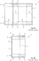
- the packing jacket 3 is shown on top of one another after the sealing of the longitudinal edges 4 of the blank 1.
- the corresponding sealing seam 10 is provided near one of the fold lines 6 of the packaging jacket 3.
- the packing jacket 3 has folded edges 6, around which the packing jacket 3 has been folded flat, so that the front section 11 and the rear section 12 of the packing jacket 3 lie one on top of the other.
- the packaging sleeves 3 can be easily stored in this way when folded flat. The subsequent unfolding around the four pre-folded fold lines 6 is then still easily possible.
- a packing jacket 3 with a rectangular cross section is then obtained.
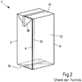
- the in the Fig. 2 Pack 7 shown can be obtained.
- the four pre-folded fold lines 6 then form the edges of the pack 7 in the region of the casing 13 of the pack 7, just as the pre-folded fold lines 6 previously formed the edges of the pack casing 3.
- the longitudinal ends 14, 15 of the package jacket 3 have been folded and sealed to form the bottom 16 of the package 7 and to form the head 17 of the package 7.
- So-called packing ears 18 are formed on the head 17 of the pack, which are folded down and placed on the jacket 13 of the pack 7 and sealed or glued there.
- the corresponding packing ears are folded inwards and are therefore no longer recognizable as such after the base 16 has been formed.
- the illustrated and in this respect preferred device 20 has a number of parallel processing lines, of which in the Fig. 3 only one processing line 23 is shown.
- Each processing line 23 is a magazine 22 with a stack 24. assigned a bundle of packing sleeves 3 folded flat around two of the folding lines 6.
- the packaging sleeves 3 have been formed as previously described from blanks 1 of a packaging material 2, the longitudinal edges 4 of which are sealed to one another.
- the packing sleeves 3 are unfolded by a feed device 25.
- the packaging sleeves 3 are unfolded by pulling away a later side surface of the corresponding packaging sleeve 3 from the stack 24 without further action around the pre-folded folding lines 6, which form the edges of the packaging sleeve 3 and of the later pack 7.
- an application device could also be provided for applying spouts (not shown) to the packing sleeves 3.
- the device 26 for forming the package 7 has a mandrel wheel 27 which, in the illustrated and in this respect preferred case, comprises six mandrels 28 and rotates counterclockwise cyclically, that is to say step by step.
- a packing jacket 3 is pushed onto the mandrel 28.
- the mandrel wheel 27 is rotated further in the next mandrel wheel position II, into which the longitudinal end 15 of the packing jacket 3 protruding relative to the mandrel 28 is heated with hot air by means of a heating unit 29.
- the heated longitudinal end 15 of the packing jacket 3 is pre-folded by a press 30 and in the following mandrel wheel position IV in the folded position it is sealed by a sealing device 31, in particular to form a base 16.
- a packing body 21 which is closed on one side is obtained, which is removed from the mandrel 28 in the subsequent mandrel wheel position V and transferred to a cell 32 of an endless transport device 33 guided in a circle.
- No working step is assigned to the mandrel 28 in the next mandrel wheel position VI.
- the number of mandrel wheel positions or mandrels 28 and the processing steps provided there can, if necessary, be as shown in FIG Fig. 1 and the associated description.
- a spout can be connected to the packaging material in at least one additional mandrel wheel position as required.
- the longitudinal end of the packing jacket closed on the mandrel wheel is preferably the head of the later packing. Whether the packing body is filled by the future head or by the future bottom plays only a minor role here.
- the packing body 21 taken from the mandrel wheel is transported with the open longitudinal end pointing upward in the associated cell 32, in particular a cell chain, by a filling machine 34.
- the package body then passes into an aseptic chamber 35, which comprises a sterilization zone 36 and a filling and sealing zone 37, through which the package bodies 21 are transported from left to right in the transport direction symbolized by the arrows.
- the packing bodies 21 do not have to be transported in a straight line, but can also be carried out in at least one arc or even in a circle.
- the packing bodies 21 are preheated in succession by a preheating device 39 by blowing with hot sterile air.
- the packing bodies 21 are then sterilized by means of a sterilizing device 40, preferably using hydrogen peroxide, whereupon the packing bodies 21 are dried by exposure to sterile air via a drying device 41 and after the transition from the sterilization zone 36 into the filling and sealing zone 37 into a filling position 42 below one Filling spout 43 are brought.
- There the packing bodies 2 are filled with food 44 one after the other.
- the filled ones Packing bodies 21 are then closed with a closing device 45 by folding the upper region of the packing body 21 and sealing.
- the filled and sealed packs 7 are then removed from the cells 32 of the transport device 33.
- the now empty cells 32 are moved further with the transport device 33 in the direction of the mandrel wheel 27 in order to accommodate further packing bodies 21 there.
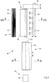
- FIG. 4A A further blank 50 of a packaging material 51 is shown, which basically corresponds to the blank 50 with regard to the packaging material 51, the blank 50 and the fold lines 52, 53, 54 Fig. 1A resembles.
- the fold lines 52, 53, 54 in particular crease lines, are arranged and designed differently.
- only two fold lines 52 are provided, which extend in a straight line in the longitudinal direction and over the entire longitudinal extent of the blank 50.
- Two further fold lines 53 divide in sections in the longitudinal direction of the blank 50 and there enclose a portion of the blank. In the corresponding area, the fold lines 53 run parallel to one another, but this is not mandatory.
- the upper edge 55 and the lower edge 56 of the blank 50 are provided with fold lines 54.
- the fold lines 54 of the lower edge 56 serve to form a bottom 57, while the fold lines 54 of the upper edge 55 serve to form a head 58 of a package 59.
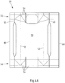
- the blank 50 is sealed along the longitudinal edges 60 to form a sealing seam 61 to form a packaging jacket 63, the front 64 and rear 64 'of which in the 4B-C are shown.
- the packing jacket 62 is folded on the two fold lines 52 which run in a straight line in the longitudinal direction of the packing jacket 62, forming the folding edges 65, so that the front side 64 and the rear side 64 'of the packing jacket 62 abut one another.
- the pack 59 has a flat bottom 57 which is oriented perpendicular to the longitudinal extent of the pack 59.
- the head 58 of the pack 59 is oriented obliquely to the longitudinal extent of the pack 59 and thus forms a pack gable 66.
- the pack gable 66 has a larger front gable surface 67 which is larger than the rear, smaller gable surface 71 arranged on the other side of the sealing seam 68
- the sealing seam 68 and adjoining sections of the head 58 form packing ears 69 on opposite sides of the packing 59, which are folded down and are attached or sealed to the jacket 70 of the packing 59.
- a larger opening section, a larger weakening and / or a large spout can be provided on the larger gable surface 67.
- neither an opening section nor a weakening or a spout is shown.
- the pack 59 no continuous fold lines 52 or fold edges 65 are provided on the front longitudinal edges of the pack 59.
- the folding edges 65 are not provided on any longitudinal edge of the pack 59 for folding the pack jacket 63 flat. Rather, the folded edges 65 are accommodated in the areas between the longitudinal edges or longitudinal edges of the pack 59. In other words, the folding edges 65 of the packaging jacket 63 are folded back again and thus no longer form folding edges of the packaging 59.
- no fold lines 52, 53, 54 extending straight in the longitudinal direction of the package are provided on the rear edges of the jacket 70 of the package 59.
- the fold lines 53 By dividing the fold lines 53, they do not run in a straight line over the entire longitudinal extent of the casing 70 of the pack 59 and also at least in sections not along the edges of the casing 70 of the pack 59, but in areas next to it.
- the device 80 for filling such packs 59 is shown.
- the device 80 largely corresponds to that in FIG Fig. 3 Device 20 shown, so that essentially the differences in the Fig. 6 device 80 compared to that shown in FIG Fig. 3 shown device 20 are described to avoid unnecessary repetitions. For this reason, the same components are in the Fig. 3 and 6 marked with the same reference numerals.
- the device 20 shown also has a pre-folding device 82 for pre-folding the packaging sleeves 63 after removing the packaging sleeves 63 from the stack 81 of the packaging sleeves 63, and a folding device 83 for unfolding the packaging sleeves 63, which are removed from the stack 81 of packaging sleeves 63 of the magazine 22.
- the pre-folding device 82 and the unfolding device 83 are combined in the illustrated and in this respect preferred device 80 to form a molding station 84 for molding the unfolded packaging jacket 63 to be transferred to the mandrel wheel 85.
- only the pre-folding device 82 or only the unfolding device 83 could be provided.
- the packing sleeves 63 are only pushed onto the mandrels 86 after they have passed through the forming station 84.
- the mandrels 86 are also different from those in the Fig. 3 illustrated thorns 28 formed.
- the mandrels 86 can namely be spread, that is to say adjusted from a narrower starting position to a wider pressing position, in the pressing position a pressing surface is provided by the mandrel 86, against which the corresponding longitudinal end 87 of the packing jacket 63 can be folded and pressed around the longitudinal end 87 to seal, in particular to seal liquid-tight.
- packing bodies 88 are ultimately formed which are delivered to the cells 32 of the transport device 33, here in the form of a cell chain.
- the in the Fig. 6 device 80 compared to that shown in FIG Fig. 3 Device 20 shown after a sealing device 89 for sealing the sealing seam 68 of the packing gable 66, a gable pre-folding device 90 for pre-folding the packing gable 66 and a sealing device 91 for sealing the Pack ears 69 provided on the jacket 70 of the pack 59.
- a shaping device 92 is provided for the final shaping of the filled and closed pack 59.
- the pack 59 receives its final shape in this shaping device 92.
- the molding device 92 is shown in such a way that the packing 59 protrudes above and below the molding device 92.
- the pack 59 is preferably received in the molding device 92 over its entire longitudinal extent.
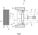
- FIG. 7 is schematically the molding station 84 of the in the Fig. 6 shown device 80 shown.
- the forming station 84 makes use of the packing sleeves 63, which are held ready in a magazine 81 in a stack 81 of packing sleeves 63 folded around two folding lines 52 or folding edges 65.
- the forming station 84 comprises a gripping arm 93 with suction cups 94, which grips the front side of the front flat-folded packing jacket 63 of the stack 81 and pulls the packing jacket 63 into and through a channel 95 of the pre-folding device 82.
- the prefolding device 82 is shown in particular in the sectional view of the forming station 84 Fig. 8 shown.
- the gripping arm 93 is shown in broken lines as it grips a packing jacket 63 of the stack 81.
- the gripping arm 93 then moves backwards in a straight line together with the packing jacket 63 and pulls the packing jacket 63 straight into a channel 95 which tapers transversely to the packing jacket 63.
- the folded edges 65 around which the packing jacket 63 has been folded flat, come into contact with the boundaries 96 of the channel 95.
- the folding edges 65 ultimately press from the inside against the channel 95, which in turn unfolds the packing jacket 63 somewhat, and the more, the further the packing jacket 63 is pulled or transported through the channel 95.
- grooves 97 aligned in the longitudinal direction of the folded edges 65 are provided on both sides of the channel 95, into which the packing jacket 63 engages with the folded edges 65 in the corresponding position.
- the suction cups 94 and thus the gripper arm 93 then detach from the packing jacket 63.
- the packing jacket 63 remains in the channel 95, held in the grooves 97.
- FIGS 9A-B shown in section.
- the mold 9 is shown by way of example with two mold halves 100, 101 in an open position. In this position, the pre-folded packing jacket 63 is taken over by the form 99, for which purpose grooves 102 are also provided in the illustrated and preferred form 99, in which the folded edges 65 of the packing jacket 63 engage.
- the packing jacket 63 is unfolded and at least essentially bears against the inner contour 103 of the mold 99.
- the packing jacket 63 can thus be brought at least approximately into the later shape of the packing 59.
- contours of a different shape can also be provided if necessary, depending on the form in which the packs are to be produced. In the Fig.
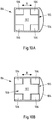
- a top view of the mandrel 86 of the mandrel wheel 85 is shown schematically.
- the mandrel 86 is in a starting position in which packing sleeves 63 can simply be pushed onto the mandrel 86 and removed again.
- the mandrel 86 does not have a rectangular or square cross section in sections.
- one side of the jacket 104 is curved outwards.
- Movable mandrel elements 106 and a static mandrel element 107 provided between them are provided on the head 105 of the illustrated and in this respect preferred mandrel 86.
- the movable mandrel elements 106 take an inner position a.
- the mandrel 86 is therefore narrower in a direction R than in that in FIG Figure 10B shown pressing position of the mandrel 86, in which the movable mandrel elements 106 are adjusted to the outside. In this position, the mandrel 86 is spread, wider and can be used to press a longitudinal end 87 of the packing jacket 63 against the mandrel 86. In the pressing position, the top of the head 105 of the mandrel 86 forms a pressing surface 108 for pressing the folded longitudinal end 87 of the packing jacket 63. The corresponding longitudinal end 87 of the packing jacket 63 can be closed, if necessary, by sealing.
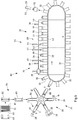
- FIG. 11 schematically shows a gable pre-folding device 90 for pre-folding the packing gable 66, wherein a filled and closed packing 59 along the sealing seam 68 of the packing gable 66 is positioned in the gable pre-folding device 90 with packing ears 69 protruding outward from the jacket 70 of the packing.
- two punches 110 are pressed from opposite sides of the pack 59 against the casing 70 of the pack 59, so that the casing 70 of the pack 59 is pressed in at the corresponding point.
- the punches 110 engage below the protruding packing ears 69.
- the package 59 is partially folded on opposite fold lines 111 below the package ears 69.
- the pack ears 69 can be bent downward in a defined manner around the correspondingly pre-folded fold lines 111 and fixed there on the jacket 70 of the pack 59.
- a shaping device 92 is shown for shaping the filled and closed pack 59, in which the packing ears 69 are preferably already fixed to the jacket 70 of the pack 59.
- the package 59 is introduced into the opened mold 112 of a package squeezer comprising at least two mold halves 114, 115. Then the mold 112 is closed and the pack 59 is pressed or squeezed from the outside.
- the mold 112 can preferably accommodate the pack 59 over its entire longitudinal extent and / or overlap at the top and bottom, in order for example in the closed state of the mold 112 to To keep pack 59 not only over the entire circumference of the pack 59, but also all round in the longitudinal extent of the pack 59, in particular to press it.
- the inner contour 116 corresponds to the shape 112 of the desired shape of the pack 59 but not to the shape of the pack 59 supplied.
- the contour 116 is not the same as that shown in FIG Figures 12A-B shown form set. Different shaped contours can be provided to produce different shaped packs.
- the shape 112 has bevelled edges 113, which the pack 59 is also intended to have. When the mold 112 is closed, the pack 59 is pressed against the inner contour 116 of the mold 112 at least substantially all around and is folded or folded in the region of the bevelled edges 113 around fold lines 53 of the pack which have already been provided.
- the area of the pack 59 between the dividing fold lines 53 is thus brought into an oblique orientation to the sides and to the rear of the pack 59 in order to emboss the desired edge shape.
- the embossed edge shape is retained even after the package 59 has been removed from the mold 112, since the edge shape has already been created in the package 59 as a result of the fold lines 53. Only the packaging material 51 had not yet been folded or folded along the fold lines 53.
Landscapes
- Engineering & Computer Science (AREA)
- Mechanical Engineering (AREA)
- Making Paper Articles (AREA)
- Auxiliary Devices For And Details Of Packaging Control (AREA)
- Cartons (AREA)
- Closing Of Containers (AREA)
- Supplying Of Containers To The Packaging Station (AREA)
- Packages (AREA)
- Package Closures (AREA)
Claims (15)
- Procédé permettant de former des corps d'emballage (88) ouverts d'un côté à partir d'enveloppes d'emballage (63) ouvertes des deux côtés pour la fabrication d'emballages remplis (59),- dans lequel les enveloppes d'emballage (63) sont maintenues à disposition pour un traitement ultérieur, sous la forme d'une pile (81), en étant pliées à plat autour d'au moins deux arêtes de pliage (65) s'étendant dans le sens longitudinal des enveloppes d'emballage (63),- dans lequel les enveloppes d'emballage (63) pliées à plat sont transmises, l'une après l'autre, de la pile (81) à un poste de formage (84),- dans lequel les enveloppes d'emballage (63) sont dépliées dans un poste de formage (84) ;- dans lequel les enveloppes d'emballage (63) dépliées sont enfilées, à partir du poste de formage (84), sur un mandrin (86) pour fermer, notamment sceller, une extrémité longitudinale (87) de l'enveloppe d'emballage (63), caractérisé en ce que les enveloppes d'emballage (63) dans le poste de formage (84) sont extraites à travers un canal (95) venant en contact avec les deux arêtes de pliage (65) opposées de l'enveloppe d'emballage (63) et se rétrécissant transversalement par rapport à l'enveloppe d'emballage (63), les enveloppes d'emballage (63) entrant en prise, à l'extrémité du canal (95), dans des côtés opposés du canal (95), avec des rainures (97) associées.
- Procédé selon la revendication 1,- dans lequel les enveloppes d'emballage (63) sont pliées à plat autour exactement de deux arêtes de pliage (65) et/ou- dans lequel l'on ne prévoit aucune ligne de pliage (52) rectiligne passant entre les arêtes de pliage (65) sur l'ensemble de l'étendue longitudinale de l'enveloppe d'emballage (63) pour le pliage du matériau d'emballage (51) et/ou- dans lequel l'on exerce une pression contre les au moins deux arêtes de pliage (65) dans le poste de formage (84) pour l'agrandissement de la section transversale libre de l'enveloppe d'emballage (63) à partir des côtés opposés de l'enveloppe d'emballage (63) de sorte que les au moins deux arêtes de pliage (65) de l'enveloppe d'emballage (63) sont rapprochées l'une de l'autre et/ou- dans lequel l'enveloppe d'emballage (63) est positionnée dans le poste de formage (84) entre au moins deux demi-moules (100, 101) d'un moule (99) et est dépliée par la fermeture du moule (99), de préférence par au moins essentiellement l'application périphérique de l'enveloppe d'emballage (63) sur le côté intérieur du moule (99).
- Procédé selon l'une des revendications 1 à 2,- dans lequel le côté de l'enveloppe d'emballage (63) pliée, formant la partie frontale de la pile (81), est, de préférence, saisi par des ventouses (94), et, est extrait de la pile (81), de préférence vers l'avant, notamment de manière rectiligne.
- Procédé selon la revendication 3,- dans lequel des limitations latérales (96) du canal (95), en tirant l'enveloppe d'emballage (63), exercent une pression telle contre les au moins deux arêtes de pliage (65) de l'enveloppe d'emballage (63) que les arêtes de pliage (65) de l'enveloppe d'emballage (63) sont rapprochées l'une de l'autre et/ou- dans lequel l'enveloppe d'emballage (63) est transportée ultérieurement dans la direction longitudinale des rainures (97), notamment dans les rainures (97) et/ou avec les rainures (97), notamment dans un dispositif de dépliage (83).
- Procédé selon l'une des revendications 1 à 4,- dans lequel l'enveloppe d'emballage (63) est déplacée dans une direction, de préférence de manière rectiligne, à travers le dispositif de pré-pliage (82) et- dans lequel, de préférence, l'enveloppe d'emballage (63) est déplacée au moins essentiellement perpendiculairement par rapport à la direction de déplacement dans le dispositif de pré-pliage (82) vers le, notamment dans le dispositif de dépliage (83).
- Procédé selon l'une des revendications 1 à 5,- dans lequel l'enveloppe d'emballage (63) avec les arêtes de pliage (65) est enfilée, espacée d'au moins une arête d'une enveloppe (104) d'un mandrin (86) et/ou au moins un coin de la tête (105) du mandrin (86), sur le mandrin (86) et- dans lequel, de préférence, l'écartement d'au moins une arête de pliage (65) des arêtes adjacentes et/ou des coins du mandrin (86) s'élève au moins à un dixième, de préférence au moins à un cinquième, notamment au moins à un tiers de l'écartement entre les arêtes adjacentes et/ou les coins et- dans lequel, plus préférablement, les arêtes de pliage (65) sont agencées sur des côtés plats et/ou sur des côtés bombés vers l'extérieur de l'enveloppe (104) du mandrin (105).
- Procédé selon l'une des revendications 1 à 6,- dans lequel, pour la fermeture de l'enveloppe d'emballage (63), une extrémité longitudinale de l'enveloppe d'emballage (63) est comprimée contre une surface de pression (108) du mandrin (86) formée seulement après avoir enfilé l'enveloppe d'emballage (63) sur le mandrin (86) et- dans lequel, de préférence après la fermeture de l'enveloppe d'emballage (63) et avant d'enlever l'enveloppe d'emballage (63) du mandrin (86), le mandrin (86) est redéplacé dans la position de départ avant d'enfiler une enveloppe d'emballage (63),- dans lequel, plus préférablement, la largeur de l'extrémité libre du mandrin (86) est agrandie pour la fermeture dans au moins une direction (R) transversalement par rapport à l'enveloppe d'emballage (63), et est réduite pour enfiler et/ou pour enlever l'enveloppe d'emballage (63).
- Procédé de fabrication d'un emballage rempli (59) comportant la formation de corps d'emballage (88) ouverts d'un côté à partir d'enveloppes d'emballage (63) ouvertes des deux côtés selon l'une des revendications 1 à 7,- dans lequel l'ouverture au niveau d'une extrémité longitudinale des corps d'emballage (88) est fermée après le remplissage, notamment par scellage, en formant des oreillettes d'emballage (69) faisant saillie vers l'extérieur par rapport à l'enveloppe (70) de l'emballage (59) et- dans lequel l'enveloppe (70) de l'emballage (59) adjacente aux oreillettes d'emballage (69) est comprimée vers l'intérieur en pliant au moins partiellement une ligne de pliage (54) pour l'application des oreillettes d'emballage (69) sur l'enveloppe (70) de l'emballage (59).
- Procédé de fabrication d'emballages remplis (59) comportant la formation de corps d'emballage (88) ouverts d'un côté à partir d'enveloppes d'emballage (63) ouvertes des deux côtés selon l'une des revendications 1 à 7, en particulier selon la revendication 8, dans lequel au moins l'enveloppe (70) de l'emballage (59) rempli et fermé est comprimée, notamment de manière périphérique, dans un moule (112) au moins en deux parties.
- Dispositif de formation de corps d'emballage (88) ouverts d'un côté à partir d'enveloppes d'emballage (63) ouvertes des deux côtés pour la fabrication d'emballages remplis (59), notamment pour la fabrication d'emballages (59) remplis, de préférence selon l'une des revendications 1 à 9, avec un magasin (22) comportant une pile (81) formée à partir d'enveloppes d'emballage (63), les enveloppes d'emballage (63) de la pile (81) étant pliées à plat autour d'au moins deux arêtes de pliage (65) passant en direction longitudinale des enveloppes d'emballage (63), un dispositif de transfert pour le transfert des enveloppes d'emballage (63) de la pile (81), l'une après l'autre, à un poste de formage (84) pour déplier les enveloppes d'emballage (63) et un dispositif d'enfilement pour enfiler des enveloppes d'emballage (63) dépliées dans le poste de formage (84) sur un mandrin (86) étant prévus, caractérisé en ce que le poste de formage (84) présente un canal (95) pour le dépliage, au moins partiellement, des enveloppes d'emballage (63) déplacées à travers le canal (95) et en ce que l'on prévoit au niveau de l'extrémité du canal (95) des rainures opposées (97) pour la réception des arêtes de pliage (65) des enveloppes d'emballage (63).
- Dispositif selon la revendication 10,
caractérisé en ce que
le poste de formage (84), de préférence un dispositif de dépliage (83), présente au moins deux matrices pour la compression et dépliage simultanés des enveloppes d'emballage (63) et, de préférence, en ce que les au moins deux matrices sont conçues en tant qu'au moins deux demi-moules (100, 101) de sorte qu'en fermant le moule (99) l'enveloppe d'emballage (63) est dépliée, et parvient, notamment, au moins essentiellement de manière périphérique, à être en contact sur le côté intérieur du moule (99). - Dispositif selon la revendication 10 ou 11,
caractérisé en ce que
un dispositif de pré-pliage (82) présente le canal (95) pour le dépliage partiel des enveloppes d'emballage (63) déplacées, notamment de manière rectiligne, à travers le canal (95) et en ce que, de préférence, la largeur du canal (95) se rétrécit dans la direction de transport des enveloppes d'emballage (63) jusqu'à un niveau qui est inférieur à la largeur des enveloppes d'emballage (63) pliées à plat, notamment logées dans le magasin (22), de sorte que des limitations latérales (96) du canal (95), lors du passage de l'enveloppe d'emballage (63), exercent une pression contre les au moins deux arêtes de pliage (65) de l'enveloppe d'emballage (63) et les arêtes de pliage (65) de l'enveloppe d'emballage (63) se rapprochent l'une de l'autre. - Dispositif selon la revendication 12,
caractérisé en ce que
des limitations latérales (96) du canal (95) sont agencées de manière stationnaire au moins lors du passage de l'enveloppe d'emballage (63) et, de préférence, en ce que l'on prévoit un dispositif d'acheminement (98) pour l'acheminement des enveloppes d'emballage (63) vers le dispositif de dépliage (83) dans l'extension longitudinale des rainures (97), notamment dans les rainures (97) et/ou avec les rainures (97). - Dispositif selon l'une des revendications 10 à 13,
caractérisé en ce que
l'on prévoit un dispositif de transfert, notamment comportant un bras de préhension (93) et un dispositif d'acheminement (98) pour déplacer l'enveloppe d'emballage (63) dans une première direction de transport à travers un dispositif de pré-pliage (82) et dans une deuxième direction de transport, orientée essentiellement perpendiculairement par rapport à la première direction de transport, dans le, de préférence à travers le, dispositif de dépliage (83) et/ou en ce que le mandrin (86), notamment la tête (105) du mandrin (86), est conçu pour le réglage entre une position de compression, de préférence plus large, et une position de départ, notamment plus étroite, pour enfiler et enlever les enveloppes d'emballage (63) et pour fournir, notamment la tête (105) du mandrin (86), dans la position de compression, la surface de pression permettant de comprimer une extrémité longitudinale (87) de l'enveloppe d'emballage (63) contre le mandrin (83). - Dispositif selon l'une des revendications 10 à 14,
caractérisé en ce que
l'on prévoit un dispositif de pré-pliage pour sommet (90) comportant deux matrices (110) pour comprimer un emballage (59) rempli et fermé adjacent aux oreillettes d'emballage (69) du sommet de l'emballage (66) en pliant au moins partiellement une ligne de pliage (54) de l'emballage (59) pour que les oreillettes d'emballage (69) soient appliquées sur l'enveloppe (70) de l'emballage (59) et, plus préférablement, en ce que l'on prévoit un moule (112) au moins en deux parties pour comprimer, notamment de manière périphérique, l'enveloppe (70) de l'emballage (59) rempli et fermé.
Priority Applications (1)
| Application Number | Priority Date | Filing Date | Title |
|---|---|---|---|
| PL17716150T PL3439971T3 (pl) | 2016-04-04 | 2017-04-03 | Sposób i urządzenie do formowania jednostronnie otwartych korpusów opakowaniowych z obustronnie otwartych rękawów opakowaniowych |
Applications Claiming Priority (3)
| Application Number | Priority Date | Filing Date | Title |
|---|---|---|---|
| DE102016106139 | 2016-04-04 | ||
| DE102016109995.3A DE102016109995A1 (de) | 2016-04-04 | 2016-05-31 | Verfahren und Vorrichtung zum Bilden von einseitig offenen Packungskörpern aus beiseitig offenen Packungsmänteln |
| PCT/EP2017/057837 WO2017174497A1 (fr) | 2016-04-04 | 2017-04-03 | Procédé et dispositif permettant de former des corps d'emballage ouverts d'un côté, constitués d'enveloppes d'emballage ouvertes des deux côtés |
Publications (2)
| Publication Number | Publication Date |
|---|---|
| EP3439971A1 EP3439971A1 (fr) | 2019-02-13 |
| EP3439971B1 true EP3439971B1 (fr) | 2020-06-10 |
Family
ID=59885632
Family Applications (6)
| Application Number | Title | Priority Date | Filing Date |
|---|---|---|---|
| EP17709081.8A Not-in-force EP3439970B1 (fr) | 2016-04-04 | 2017-03-07 | Procédé et dispositif permettant de former des corps d'emballage ouverts d'un côté, constitués d'enveloppes d'emballage ouvertes des deux côtés |
| EP17711151.5A Active EP3439964B1 (fr) | 2016-04-04 | 2017-03-16 | Dispositif et procédé de formation de surfaces de pignon d'emballages à pignon oblique |
| EP17712073.0A Active EP3439972B1 (fr) | 2016-04-04 | 2017-03-16 | Dispositif pour fermer d'un seul côté des enveloppes d'emballages pour réaliser des emballages composites |
| EP19190904.3A Withdrawn EP3581507A1 (fr) | 2016-04-04 | 2017-03-21 | Procédé de formation d'emballages fermés |
| EP17712477.3A Active EP3439974B1 (fr) | 2016-04-04 | 2017-03-21 | Dispositif pour façonner des emballages fermés |
| EP17716150.2A Active EP3439971B1 (fr) | 2016-04-04 | 2017-04-03 | Procédé et dispositif permettant de former des corps d'emballage ouverts d'un côté à partir d'enveloppes d'emballage ouvertes des deux côtés |
Family Applications Before (5)
| Application Number | Title | Priority Date | Filing Date |
|---|---|---|---|
| EP17709081.8A Not-in-force EP3439970B1 (fr) | 2016-04-04 | 2017-03-07 | Procédé et dispositif permettant de former des corps d'emballage ouverts d'un côté, constitués d'enveloppes d'emballage ouvertes des deux côtés |
| EP17711151.5A Active EP3439964B1 (fr) | 2016-04-04 | 2017-03-16 | Dispositif et procédé de formation de surfaces de pignon d'emballages à pignon oblique |
| EP17712073.0A Active EP3439972B1 (fr) | 2016-04-04 | 2017-03-16 | Dispositif pour fermer d'un seul côté des enveloppes d'emballages pour réaliser des emballages composites |
| EP19190904.3A Withdrawn EP3581507A1 (fr) | 2016-04-04 | 2017-03-21 | Procédé de formation d'emballages fermés |
| EP17712477.3A Active EP3439974B1 (fr) | 2016-04-04 | 2017-03-21 | Dispositif pour façonner des emballages fermés |
Country Status (8)
| Country | Link |
|---|---|
| US (5) | US20190112082A1 (fr) |
| EP (6) | EP3439970B1 (fr) |
| JP (4) | JP2019510705A (fr) |
| CN (5) | CN109153467A (fr) |
| DE (5) | DE102016109979A1 (fr) |
| ES (4) | ES2802449T3 (fr) |
| PL (4) | PL3439964T3 (fr) |
| WO (5) | WO2017174280A1 (fr) |
Families Citing this family (27)
| Publication number | Priority date | Publication date | Assignee | Title |
|---|---|---|---|---|
| US8915365B2 (en) * | 2013-03-15 | 2014-12-23 | Altria Client Services Inc. | Packaging sleeve |
| EP3219631B1 (fr) * | 2016-03-18 | 2018-11-07 | Tetra Laval Holdings & Finance S.A. | Dispositif de formage et procédé de formage d'un emballage en un emballage fini, unité de pliage pour former des emballages scellés de produits alimentaires liquides |
| DE102016109979A1 (de) * | 2016-04-04 | 2017-10-05 | Sig Technology Ag | Vorrichtung und Verfahren zum Formen von geschlossenen Verpackungen |
| DE102017127327A1 (de) * | 2017-11-20 | 2019-05-23 | Sig Technology Ag | Füllmaschine mit Kühleinrichtungen zum Kühlen unterschiedlicher Anlagenteile |
| DE102018102515B4 (de) * | 2018-02-05 | 2022-05-25 | Project Service & Produktion GmbH | Verfahren und Vorrichtung zum Verpacken von mehreren Gegenständen |
| DE102018102514B4 (de) * | 2018-02-05 | 2022-05-25 | Project Service & Produktion GmbH | Verfahren und Vorrichtung zur Bereitstellung einer Umverpackung |
| CN108482733B (zh) * | 2018-04-17 | 2024-01-05 | 广东穗方源实业有限公司 | 用于封装大米的压制成型装置 |
| DE102018113606A1 (de) | 2018-06-07 | 2019-12-12 | Sig Technology Ag | Vorrichtung mit Formstation zum Bilden von einseitig offenen Packungskörpern |
| DE102019101816A1 (de) | 2019-01-25 | 2020-07-30 | Sig Technology Ag | Verfahren und Vorrichtung zum wenigstens teilweisen Auffalten von flachgefalteten Packungsmänteln |
| DE102019110914A1 (de) | 2019-04-26 | 2020-10-29 | Sig Technology Ag | Verfahren und Vorrichtung zum wenigstens teilweisen Auffalten von flachgefalteten Packungsmänteln |
| DE102019114635A1 (de) | 2019-05-31 | 2020-12-03 | Sig Technology Ag | Vorrichtung und verfahren zum nachformen der giebelflächen von verpackungen mit schrägem giebel |
| CN114845937A (zh) | 2019-07-30 | 2022-08-02 | 安海斯-布希英博有限公司 | 用于二次包装的成形工具 |
| EP3842224A1 (fr) | 2019-12-27 | 2021-06-30 | Anheuser-Busch InBev S.A. | Outil de formage pour emballages secondaires |
| DE102019132431A1 (de) * | 2019-11-29 | 2021-06-02 | Sig Technology Ag | Packung mit geschwungenen Kanten |
| DE102019132426B4 (de) | 2019-11-29 | 2024-12-24 | Sig Technology Ag | Flächenförmiges Verbundmaterial, Packungsmantel und Packung mit trapezförmigem Giebel |
| CN115279297A (zh) * | 2020-01-15 | 2022-11-01 | Devicor医疗产业收购公司 | 弹性体薄套筒折叠机构 |
| EP3854290A1 (fr) | 2020-01-24 | 2021-07-28 | Universität Zürich | Laryngoscope lumineux à pointe pour éclairage trans-tissulaire |
| DE102020109977A1 (de) | 2020-04-09 | 2021-10-14 | Sig Technology Ag | Vorrichtung zum einseitigen Verschließen von Packungsmänteln für die Herstellung von Verbundpackungen |
| KR102186567B1 (ko) * | 2020-08-13 | 2020-12-03 | 송상근 | 평면으로 접히고 접힌부분을 눌러 펼쳐젓을 때 상단이 원통형을 이루는 일회용 접이식 종이컵 |
| DE102020121953A1 (de) | 2020-08-21 | 2022-02-24 | Sig Technology Ag | Vorrichtung zum Formen der Giebelflächen von Verpackungen |
| CN111977060A (zh) * | 2020-09-02 | 2020-11-24 | 安徽和县太阳岛食品有限公司 | 一种真空包装零食用自动化真空包装设备及其工作方法 |
| EP4001137B1 (fr) * | 2020-11-16 | 2025-03-19 | Uhlmann Pac-Systeme GmbH & Co. KG | Procédé de manipulation de matière d'emballage en forme de bande |
| KR102784995B1 (ko) | 2020-12-03 | 2025-03-20 | 엘지디스플레이 주식회사 | 표시 장치 |
| CN113602589A (zh) * | 2021-07-28 | 2021-11-05 | 淮安市昊天自动化设备有限公司 | 一种卧式高速开箱机及开箱方法 |
| IL312010A (en) * | 2021-10-08 | 2024-06-01 | Ecocaps S R L | Mechatronic and modular encapsulating machine for food or beverage containers |
| DE102022115881A1 (de) | 2022-06-27 | 2023-12-28 | Sig Combibloc Services Ag | Verfahren und vorrichtung zum bilden von einseitig offenen packungskörpern aus beidseitig ofenen packungsmänteln |
| CN117533594B (zh) * | 2024-01-09 | 2024-03-12 | 唐山兴业纸制品有限公司 | 一种基于包装箱生产线的双侧挤压式展开结构 |
Family Cites Families (102)
| Publication number | Priority date | Publication date | Assignee | Title |
|---|---|---|---|---|
| DE160669C (fr) | ||||
| DE152605C (fr) | ||||
| DE160476C (fr) | ||||
| US2541607A (en) * | 1946-09-27 | 1951-02-13 | Shellmar Products Corp | Carton handling machine |
| US2514867A (en) * | 1947-04-09 | 1950-07-11 | Pneumatic Scale Corp | Method and apparatus for producing a package |
| US2630742A (en) * | 1949-02-02 | 1953-03-10 | Molins Machine Co Ltd | Device for opening shells of slide and shell cartons |
| DE1063890B (de) * | 1955-05-05 | 1959-08-20 | Hesser Ag Maschf | Verstellbarer Falzdorn fuer Maschinen zum Herstellen oder Formen von eckigen Beuteln u. dgl. |
| US3187646A (en) * | 1959-12-04 | 1965-06-08 | Ex Cell O Corp | Packaging machine for erecting and sealing plastic coated paperboard containers |
| DE1187178B (de) | 1963-05-09 | 1965-02-11 | Holstein & Kappert Maschf | Vorrichtung zum Herstellen von Quaderpackungen |
| DE1461991A1 (de) * | 1965-04-20 | 1969-03-06 | Mineraloel Ag | Verfahren und Einrichtung zur Herstellung von stapelbarem Block-Bitumen |
| US3533333A (en) * | 1968-04-01 | 1970-10-13 | Emhart Corp | Machine for erecting cases |
| JPS4612938Y1 (fr) | 1968-10-16 | 1971-05-08 | ||
| SE335090B (fr) * | 1968-10-30 | 1971-05-10 | Tetra Pak Int | |
| US3750931A (en) * | 1972-06-19 | 1973-08-07 | Hoerner Waldorf Corp | Carton opening means |
| JPS5032667B1 (fr) | 1972-09-01 | 1975-10-23 | ||
| DK139215C (da) * | 1973-07-24 | 1979-07-09 | Jagenberg Werke Ag | Apparat til indfoldning og plan forsegling af en vaesketaet kartons bund |
| US3896711A (en) * | 1974-03-13 | 1975-07-29 | Container Corp | Apparatus for erecting carton tubes |
| US4131057A (en) * | 1976-09-29 | 1978-12-26 | Phillips Petroleum Company | Apparatus for forming a convoluted container sidewall |
| JPS5756966Y2 (fr) * | 1979-04-18 | 1982-12-07 | ||
| GB2074124A (en) * | 1980-01-15 | 1981-10-28 | Ferry Pickering Sales Ltd | Paper tube containers |
| SE436272B (sv) | 1981-03-27 | 1984-11-26 | Tetra Pak Int | Maskin for bearbetning av forpackningsbehallare |
| US4510732A (en) | 1982-03-22 | 1985-04-16 | Tetra Pak International Ab | Machine for the processing of packing containers |
| JPS5943115U (ja) * | 1982-09-13 | 1984-03-21 | 田辺 正治 | 底張り時における包装紙筒の保持装置 |
| JPS602404A (ja) * | 1983-06-17 | 1985-01-08 | 東洋製罐株式会社 | 加熱充填密封包装体の製法 |
| US4530692A (en) * | 1983-08-25 | 1985-07-23 | Consolidated Papers, Inc. | Apparatus for opening folded corrugated cartons |
| US4614079A (en) * | 1984-03-30 | 1986-09-30 | Toppan Printing Co., Ltd. | Automatic packaging system |
| SE454682B (sv) * | 1985-10-03 | 1988-05-24 | Tetra Pak Ab | Sett och maskin for framstellning av forpackningsbehallare |
| JPH0247003Y2 (fr) | 1986-06-09 | 1990-12-11 | ||
| DE8622831U1 (de) * | 1986-08-28 | 1988-01-07 | Icoma Packtechnik Gmbh, 77855 Achern | Form- und Fülleinrichtung für Verpackungen aus Karton |
| JPH0729391B2 (ja) | 1986-09-20 | 1995-04-05 | 大日本印刷株式会社 | 容器移送案内装置 |
| JPS63141108U (fr) * | 1987-03-04 | 1988-09-16 | ||
| JPH01177856A (ja) | 1988-01-05 | 1989-07-14 | Toshiba Corp | 電滋ポンプ |
| DE3804791C2 (de) * | 1988-02-16 | 1993-10-07 | Tetra Pak Rausing & Co Kg | Vorrichtung zum Auffalten von flachliegenden Hülsen |
| US4983154A (en) * | 1988-04-29 | 1991-01-08 | Tokyo Automatic Machinery Works, Ltd. | Carton assembling method and equipment |
| JP2739483B2 (ja) * | 1988-08-24 | 1998-04-15 | 日本テトラパック株式会社 | 平らにされた筒状ブランクの立上げ方法とその装置 |
| US4895193A (en) * | 1988-10-14 | 1990-01-23 | Elopak Systems A.G. | Container filling system |
| DE3835390A1 (de) | 1988-10-18 | 1990-04-19 | Pkl Verpackungssysteme Gmbh | Quaderfoermige packung, insbesondere aus einem karton-kunststoff-verbund fuer fluessigkeiten, suppen od. dgl. und verfahren zu deren herstellung |
| US4934994A (en) * | 1988-11-22 | 1990-06-19 | Milliken Packaging | Mandrel insertion mechanism in a carton container-forming device |
| JP2813820B2 (ja) * | 1989-09-13 | 1998-10-22 | 四国化工機株式会社 | 容器成形装置 |
| JP2748043B2 (ja) | 1990-05-24 | 1998-05-06 | エービー テトラパック | 包装容器の底部形成用マンドレルの冷却方法と使用するマンドレル |
| JPH07110651B2 (ja) | 1990-11-30 | 1995-11-29 | シーケーディ株式会社 | 包装装置 |
| JPH0526806U (ja) * | 1990-12-25 | 1993-04-06 | 四国化工機株式会社 | ブランク供給装置 |
| JPH0533914U (ja) | 1991-09-06 | 1993-05-07 | 三菱マテリアル株式会社 | 管の加工治具 |
| DE4232956C2 (de) * | 1992-10-01 | 2002-02-21 | Jagenberg Diana Gmbh | Verfahren und Vorrichtung zum Nachbrechen der Längsrillinien bei der Herstellung von quaderförmigen Faltschachteln |
| JPH0686926U (ja) * | 1993-05-28 | 1994-12-20 | 凸版印刷株式会社 | 容器底部成形装置用マンドレル |
| DE4409947C2 (de) * | 1994-03-23 | 1997-07-17 | Pkl Verpackungssysteme Gmbh | Quaderförmige Flachgiebelpackung mit Giebelnaht |
| US5536231A (en) * | 1994-06-21 | 1996-07-16 | Tetra Laval Holdings & Finance S.A. | Apparatus and method for picking and erecting carton blanks |
| AU3742995A (en) | 1994-11-30 | 1996-06-19 | Tetra Laval Holdings & Finance Sa | Adjustable mandrel |
| JPH08300514A (ja) * | 1995-04-28 | 1996-11-19 | Tomy Ltd | 押出し成形板用エッジ部品および押出し成形板組立体 |
| US5628450A (en) * | 1995-06-12 | 1997-05-13 | Willamette Industries | Octagonal box structure and setting up apparatus |
| CN1141151A (zh) * | 1995-07-25 | 1997-01-29 | 北京市畅达贸易发展公司 | 纸板热压成型连盖饭盒及其制作方法 |
| JPH0986510A (ja) * | 1995-09-22 | 1997-03-31 | Dainippon Printing Co Ltd | カートンの成形装置 |
| JPH1029249A (ja) | 1996-07-15 | 1998-02-03 | Shikoku Kakoki Co Ltd | 包装機械における耳着け装置 |
| JP3827777B2 (ja) * | 1996-09-17 | 2006-09-27 | 四国化工機株式会社 | 包装容器成形フラップ |
| JP3766157B2 (ja) * | 1996-12-27 | 2006-04-12 | 日本テトラパック株式会社 | パッケージ製造装置 |
| US5809743A (en) * | 1997-03-28 | 1998-09-22 | Tetra Laval Holdings & Finance, Sa | Top folding and sealing apparatus for forming and sealing the fin of a gabled carton |
| US5809741A (en) * | 1997-04-22 | 1998-09-22 | Tetra Laval Holdings & Finance, Sa | Carton concaving device |
| JPH1177856A (ja) * | 1997-09-08 | 1999-03-23 | Nippon Tetra Pack Kk | パッケージ製造装置の成形型 |
| DE19920495A1 (de) * | 1999-05-05 | 2000-11-09 | Bosch Gmbh Robert | Vorrichtung zum Entnehmen und Übergeben von Faltschachteln |
| GB9923205D0 (en) * | 1999-09-30 | 1999-12-01 | Meltog Ltd | Mounting mechanism for tin box manufacturing apparatus |
| US6560950B1 (en) | 2000-02-28 | 2003-05-13 | Tetra Laval Holdings & Finance, Sa | Overfolding device |
| JP3858610B2 (ja) * | 2001-02-28 | 2006-12-20 | 凸版印刷株式会社 | カートン供給装置 |
| JP4788086B2 (ja) * | 2001-09-07 | 2011-10-05 | 四国化工機株式会社 | 包装機械 |
| US6609355B2 (en) * | 2001-10-15 | 2003-08-26 | International Paper Company | Adjustable carton stop |
| US6764436B1 (en) * | 2003-01-11 | 2004-07-20 | Mark Stanley Mazurek | Method and apparatus for squaring cases |
| AT500778B1 (de) * | 2003-05-06 | 2007-11-15 | Haas Franz Waffelmasch | Anlage oder vorrichtung zum konfektionieren von steifen, einseitig offenen behältern |
| DE102004058512B4 (de) | 2004-12-04 | 2007-02-22 | Sig Technology Ag | Verfahren und Vorrichtung zum Befüllen von kontinuierlich in Zellenkäfigen transportierten Behältern und dafür bestimmter Zellenkäfig |
| ITPR20050070A1 (it) * | 2005-11-16 | 2007-05-17 | P E Promec Sistemi Srl | Apparato per formare contenitori di cartone. |
| GB0525979D0 (en) * | 2005-12-21 | 2006-02-01 | Elopak Systems | Improvements in or relating to packaging |
| ES2315993T3 (es) | 2006-01-31 | 2009-04-01 | TETRA LAVAL HOLDINGS & FINANCE SA | Unidad modular para aplicar dispositivos de apertura a envases de productos alimenticios vertibles. |
| DE602006003407D1 (de) | 2006-02-28 | 2008-12-11 | Tetra Laval Holdings & Finance | Biegevorrichtung zur Formung von versiegelte Verpackungen mit fliessfähigen Nahrungsmittel |
| EP1826127A1 (fr) * | 2006-02-28 | 2007-08-29 | Tetra Laval Holdings & Finance S.A. | Unité de pliage pour machine pour l'emballage de produits alimentaires versables |
| US7559884B2 (en) * | 2006-06-08 | 2009-07-14 | Raymond George Montague Kisch | Smart mandrel for container forming machines |
| DE102006032638B4 (de) * | 2006-07-13 | 2010-11-11 | Sig Technology Ag | Karton/Kunststoff-Verbundpackung mit abziehbarem Deckel und Verfahren zu ihrer Herstellung |
| DE102006042506B4 (de) | 2006-09-07 | 2015-04-16 | Sig Technology Ag | Verfahren und Vorrichtung zur Herstellung einer Karton/Kunststoff-Verbundverpackung |
| GB0717191D0 (en) | 2007-07-20 | 2007-10-17 | Elopak Systems | Improvements in or relating to packaging |
| GB0809082D0 (en) | 2008-05-20 | 2008-06-25 | Elopak Systems | Improvements in or relating to container blanks and containers |
| IT1391875B1 (it) | 2008-11-14 | 2012-01-27 | Tetra Laval Holdings & Finance | Dispositivo pressatore atto ad esercitare una pressione su un dispositivo di apertura applicato su una confezione contenente un prodotto alimentare versabile in un tubo di materiale di confezionamento |
| GB0920543D0 (en) * | 2009-11-24 | 2010-01-06 | Elopak Systems | Apparatus and method |
| EP2345590B2 (fr) * | 2010-01-15 | 2016-07-27 | Graphic Packaging International, Inc. | Barrette d'entraînement pour octogone |
| US8647247B2 (en) * | 2010-05-13 | 2014-02-11 | Douglas Machine Inc. | Continuous motion case former |
| EP2392517A1 (fr) | 2010-06-07 | 2011-12-07 | Tetra Laval Holdings & Finance S.A. | Emballage scellé pour produits alimentaires versables et matériau de conditionnement pour produire des emballages scellés de produits alimentaires versables |
| DE102010050502A1 (de) * | 2010-11-08 | 2012-05-10 | Sig Technology Ag | Vorrichtung und Verfahren zur Herstellung einer Verpackung |
| DK2468641T3 (da) | 2010-12-21 | 2013-10-14 | Tetra Laval Holdings & Finance | Foldeindretning til dannelse af forseglede emballager til hældbare fødevarer |
| US9498928B2 (en) * | 2011-03-22 | 2016-11-22 | Illinois Tool Works Inc. | Forming conveyor for a carton |
| CN202208386U (zh) * | 2011-08-22 | 2012-05-02 | 毛传云 | 一种全自动装箱系统 |
| CN202219866U (zh) * | 2011-08-24 | 2012-05-16 | 郑建村 | 一种全自动瓷砖包装设备的取箱装箱装置 |
| DE102011054327A1 (de) * | 2011-10-10 | 2013-04-11 | Elopak Systems Ag | Füllmaschine zum Abfüllen von Produkten in Packungsbehälter sowie Verfahren hierzu |
| EP2586716B1 (fr) * | 2011-10-31 | 2014-08-06 | Tetra Laval Holdings & Finance S.A. | Unité de conditionnement pour machines de conditionnement de produits alimentaires pouvant être versés |
| EP2586718B1 (fr) | 2011-10-31 | 2014-05-28 | Tetra Laval Holdings & Finance S.A. | Unité de pliage de production de paquets pliés de produits alimentaires pouvant être versés à partir de paquets scellés relatifs |
| ES2535810T3 (es) * | 2011-10-31 | 2015-05-18 | Tetra Laval Holdings & Finance S.A. | Unidad de plegado y método para producir envases de productos alimenticios que se pueden verter |
| EP2631188B1 (fr) * | 2012-02-24 | 2014-07-23 | Tetra Laval Holdings & Finance S.A. | Unité de conditionnement pour machines de conditionnement de produits alimentaires pouvant être versés |
| DE102012102812A1 (de) * | 2012-03-30 | 2013-10-02 | Elopak Systems Ag | Vorrichtung und Verfahren zum Reduzieren von Rückstellkräften von Packungsmänteln in einer Füllmaschine |
| DE102013107429B3 (de) * | 2013-07-12 | 2014-06-05 | Sig Technology Ag | Vorrichtung und Verfahren zum flüssigkeitsdichten Versiegeln von zwei sich teilweise überlappenden Verpackungsteilen und damit/danach hergestellter Behälter |
| DE102013015638A1 (de) | 2013-09-23 | 2015-03-26 | Sig Technology Ag | Vorrichtung zum Herstellen einer Verbundverpackung |
| DE102014102333A1 (de) | 2014-02-24 | 2015-08-27 | Sig Technology Ag | Vorrichtung und Verfahren zur Vorfaltung von Packungsmänteln |
| DE102015101751A1 (de) * | 2015-02-06 | 2016-08-11 | Sig Technology Ag | Verfahren zum Füllen von Packungen mit wechselnden Produkten in einer Füllmaschine |
| DE102016003826A1 (de) | 2016-04-04 | 2017-10-05 | Sig Technology Ag | Packungsmantel, Verpackung und Verfahren zur Herstellung einer Verpackung |
| DE102016109979A1 (de) * | 2016-04-04 | 2017-10-05 | Sig Technology Ag | Vorrichtung und Verfahren zum Formen von geschlossenen Verpackungen |
| DE102016003829A1 (de) | 2016-04-04 | 2017-10-05 | Sig Technology Ag | Packungsmantel, Packung und Verfahren zur Herstellung einer Packung |
| DE102016003824A1 (de) | 2016-04-04 | 2017-10-05 | Sig Technology Ag | Packungsmantel, Verpackung und Verfahren zur Herstellung einer Verpackung |
| DE102017114814A1 (de) * | 2017-07-03 | 2019-01-03 | Sig Technology Ag | Verfahren und Vorrichtung zum Bilden von einseitig offenen Packungskörpern mit einem oszillierenden Greifer |
-
2016
- 2016-05-31 DE DE102016109979.1A patent/DE102016109979A1/de not_active Ceased
- 2016-05-31 DE DE102016109980.5A patent/DE102016109980A1/de not_active Ceased
- 2016-05-31 DE DE102016109996.1A patent/DE102016109996A1/de not_active Ceased
- 2016-05-31 DE DE102016110008.0A patent/DE102016110008A1/de not_active Ceased
- 2016-05-31 DE DE102016109995.3A patent/DE102016109995A1/de not_active Ceased
-
2017
- 2017-03-07 WO PCT/EP2017/055301 patent/WO2017174280A1/fr not_active Ceased
- 2017-03-07 US US16/090,378 patent/US20190112082A1/en not_active Abandoned
- 2017-03-07 EP EP17709081.8A patent/EP3439970B1/fr not_active Not-in-force
- 2017-03-07 CN CN201780022350.XA patent/CN109153467A/zh active Pending
- 2017-03-07 JP JP2019502143A patent/JP2019510705A/ja not_active Withdrawn
- 2017-03-16 US US16/090,365 patent/US11745903B2/en active Active
- 2017-03-16 ES ES17711151T patent/ES2802449T3/es active Active
- 2017-03-16 JP JP2018551963A patent/JP6899843B2/ja active Active
- 2017-03-16 ES ES17712073T patent/ES2792086T3/es active Active
- 2017-03-16 JP JP2018551964A patent/JP6921110B2/ja active Active
- 2017-03-16 EP EP17711151.5A patent/EP3439964B1/fr active Active
- 2017-03-16 US US16/090,340 patent/US10926896B2/en active Active
- 2017-03-16 CN CN201780022555.8A patent/CN108883847B/zh active Active
- 2017-03-16 EP EP17712073.0A patent/EP3439972B1/fr active Active
- 2017-03-16 CN CN201780022497.9A patent/CN108883845B/zh active Active
- 2017-03-16 WO PCT/EP2017/056215 patent/WO2017174321A1/fr not_active Ceased
- 2017-03-16 PL PL17711151T patent/PL3439964T3/pl unknown
- 2017-03-16 WO PCT/EP2017/056199 patent/WO2017174318A1/fr not_active Ceased
- 2017-03-16 PL PL17712073T patent/PL3439972T3/pl unknown
- 2017-03-21 US US16/079,662 patent/US20190055045A1/en not_active Abandoned
- 2017-03-21 CN CN201780022283.1A patent/CN108883850B/zh active Active
- 2017-03-21 EP EP19190904.3A patent/EP3581507A1/fr not_active Withdrawn
- 2017-03-21 PL PL17712477T patent/PL3439974T3/pl unknown
- 2017-03-21 EP EP17712477.3A patent/EP3439974B1/fr active Active
- 2017-03-21 ES ES17712477T patent/ES2793015T3/es active Active
- 2017-03-21 WO PCT/EP2017/056659 patent/WO2017174347A1/fr not_active Ceased
- 2017-04-03 WO PCT/EP2017/057837 patent/WO2017174497A1/fr not_active Ceased
- 2017-04-03 ES ES17716150T patent/ES2803375T3/es active Active
- 2017-04-03 PL PL17716150T patent/PL3439971T3/pl unknown
- 2017-04-03 US US16/090,387 patent/US11203448B2/en active Active
- 2017-04-03 JP JP2019502154A patent/JP6864737B2/ja active Active
- 2017-04-03 EP EP17716150.2A patent/EP3439971B1/fr active Active
- 2017-04-03 CN CN201780022294.XA patent/CN109311548B/zh active Active
Non-Patent Citations (1)
| Title |
|---|
| None * |
Also Published As
Similar Documents
| Publication | Publication Date | Title |
|---|---|---|
| EP3439971B1 (fr) | Procédé et dispositif permettant de former des corps d'emballage ouverts d'un côté à partir d'enveloppes d'emballage ouvertes des deux côtés | |
| EP3649052B1 (fr) | Procédé et dispositif de fabrication de corps d'emballage ouverts d'un côté à l'aide d'un préhenseur oscillant | |
| EP3366595B1 (fr) | Procédé et dispositif de fabrication de paquets (de cigarettes) | |
| WO2015169280A1 (fr) | Procédé et dispositif de fabrication de pièces moulées à partir d'une bande de matière fibreuse | |
| EP0162119B1 (fr) | Dispositif pour la fabrication d'un emballage à partir d'un flan plat | |
| WO2015124396A9 (fr) | Dispositif et procédé de pré-pliage d'enveloppes d'emballage | |
| EP3489005B1 (fr) | Outil de moulage et procédé de fabrication d'un emballage | |
| EP3049333B1 (fr) | Dispositif de fabrication d'un emballage composite | |
| DE19711799A1 (de) | Verfahren und Vorrichtung zum Herstellen von rohrförmigen Hohlkörpern | |
| EP2729375B1 (fr) | Machine d'emballage dotée d'un moyen de fixation d'une garniture intérieure sur un élément structurel | |
| WO2020216564A1 (fr) | Procédé et dispositif de dépliage au moins partiel d'enveloppes d'emballage pliées à plat | |
| EP3350082A1 (fr) | Procédé et dispositif d'application d'un bord | |
| WO2019234104A1 (fr) | Arrangement avec station de façonnage pour former des corps d'emballage ouverts d'un côté | |
| EP4161767A1 (fr) | Dispositif et procédé pour fabriquer des contenants pourvus d'un bord fonctionnel à partir de découpes planes | |
| DE102020109977A1 (de) | Vorrichtung zum einseitigen Verschließen von Packungsmänteln für die Herstellung von Verbundpackungen | |
| WO2020151934A1 (fr) | Procédé et dispositif de pliage au moins partiel d'enveloppes d'emballage pliées à plat | |
| EP3976480B1 (fr) | Dispositif et procédé de postformage des surfaces de pignon d'emballages à pignon oblique | |
| DE102022115881A1 (de) | Verfahren und vorrichtung zum bilden von einseitig offenen packungskörpern aus beidseitig ofenen packungsmänteln | |
| DE1679904B2 (de) | Verfahren und Vorrichtung zur Herstellung dünnwandiger einseitig offener Verpackungsbehälter aus thermoplastischem Kunststoff |
Legal Events
| Date | Code | Title | Description |
|---|---|---|---|
| STAA | Information on the status of an ep patent application or granted ep patent |
Free format text: STATUS: UNKNOWN |
|
| STAA | Information on the status of an ep patent application or granted ep patent |
Free format text: STATUS: THE INTERNATIONAL PUBLICATION HAS BEEN MADE |
|
| PUAI | Public reference made under article 153(3) epc to a published international application that has entered the european phase |
Free format text: ORIGINAL CODE: 0009012 |
|
| STAA | Information on the status of an ep patent application or granted ep patent |
Free format text: STATUS: REQUEST FOR EXAMINATION WAS MADE |
|
| 17P | Request for examination filed |
Effective date: 20181002 |
|
| AK | Designated contracting states |
Kind code of ref document: A1 Designated state(s): AL AT BE BG CH CY CZ DE DK EE ES FI FR GB GR HR HU IE IS IT LI LT LU LV MC MK MT NL NO PL PT RO RS SE SI SK SM TR |
|
| AX | Request for extension of the european patent |
Extension state: BA ME |
|
| DAV | Request for validation of the european patent (deleted) | ||
| DAX | Request for extension of the european patent (deleted) | ||
| GRAP | Despatch of communication of intention to grant a patent |
Free format text: ORIGINAL CODE: EPIDOSNIGR1 |
|
| STAA | Information on the status of an ep patent application or granted ep patent |
Free format text: STATUS: GRANT OF PATENT IS INTENDED |
|
| INTG | Intention to grant announced |
Effective date: 20200103 |
|
| GRAS | Grant fee paid |
Free format text: ORIGINAL CODE: EPIDOSNIGR3 |
|
| GRAA | (expected) grant |
Free format text: ORIGINAL CODE: 0009210 |
|
| STAA | Information on the status of an ep patent application or granted ep patent |
Free format text: STATUS: THE PATENT HAS BEEN GRANTED |
|
| AK | Designated contracting states |
Kind code of ref document: B1 Designated state(s): AL AT BE BG CH CY CZ DE DK EE ES FI FR GB GR HR HU IE IS IT LI LT LU LV MC MK MT NL NO PL PT RO RS SE SI SK SM TR |
|
| REG | Reference to a national code |
Ref country code: GB Ref legal event code: FG4D Free format text: NOT ENGLISH |
|
| REG | Reference to a national code |
Ref country code: CH Ref legal event code: EP Ref country code: AT Ref legal event code: REF Ref document number: 1278991 Country of ref document: AT Kind code of ref document: T Effective date: 20200615 |
|
| REG | Reference to a national code |
Ref country code: DE Ref legal event code: R082 Ref document number: 502017005647 Country of ref document: DE Representative=s name: COHAUSZ & FLORACK PATENT- UND RECHTSANWAELTE P, DE |
|
| REG | Reference to a national code |
Ref country code: DE Ref legal event code: R096 Ref document number: 502017005647 Country of ref document: DE |
|
| REG | Reference to a national code |
Ref country code: IE Ref legal event code: FG4D Free format text: LANGUAGE OF EP DOCUMENT: GERMAN |
|
| REG | Reference to a national code |
Ref country code: LT Ref legal event code: MG4D |
|
| PG25 | Lapsed in a contracting state [announced via postgrant information from national office to epo] |
Ref country code: GR Free format text: LAPSE BECAUSE OF FAILURE TO SUBMIT A TRANSLATION OF THE DESCRIPTION OR TO PAY THE FEE WITHIN THE PRESCRIBED TIME-LIMIT Effective date: 20200911 Ref country code: FI Free format text: LAPSE BECAUSE OF FAILURE TO SUBMIT A TRANSLATION OF THE DESCRIPTION OR TO PAY THE FEE WITHIN THE PRESCRIBED TIME-LIMIT Effective date: 20200610 Ref country code: LT Free format text: LAPSE BECAUSE OF FAILURE TO SUBMIT A TRANSLATION OF THE DESCRIPTION OR TO PAY THE FEE WITHIN THE PRESCRIBED TIME-LIMIT Effective date: 20200610 Ref country code: SE Free format text: LAPSE BECAUSE OF FAILURE TO SUBMIT A TRANSLATION OF THE DESCRIPTION OR TO PAY THE FEE WITHIN THE PRESCRIBED TIME-LIMIT Effective date: 20200610 Ref country code: NO Free format text: LAPSE BECAUSE OF FAILURE TO SUBMIT A TRANSLATION OF THE DESCRIPTION OR TO PAY THE FEE WITHIN THE PRESCRIBED TIME-LIMIT Effective date: 20200910 |
|
| REG | Reference to a national code |
Ref country code: NL Ref legal event code: MP Effective date: 20200610 |
|
| PG25 | Lapsed in a contracting state [announced via postgrant information from national office to epo] |
Ref country code: HR Free format text: LAPSE BECAUSE OF FAILURE TO SUBMIT A TRANSLATION OF THE DESCRIPTION OR TO PAY THE FEE WITHIN THE PRESCRIBED TIME-LIMIT Effective date: 20200610 Ref country code: RS Free format text: LAPSE BECAUSE OF FAILURE TO SUBMIT A TRANSLATION OF THE DESCRIPTION OR TO PAY THE FEE WITHIN THE PRESCRIBED TIME-LIMIT Effective date: 20200610 Ref country code: BG Free format text: LAPSE BECAUSE OF FAILURE TO SUBMIT A TRANSLATION OF THE DESCRIPTION OR TO PAY THE FEE WITHIN THE PRESCRIBED TIME-LIMIT Effective date: 20200910 Ref country code: LV Free format text: LAPSE BECAUSE OF FAILURE TO SUBMIT A TRANSLATION OF THE DESCRIPTION OR TO PAY THE FEE WITHIN THE PRESCRIBED TIME-LIMIT Effective date: 20200610 |
|
| PG25 | Lapsed in a contracting state [announced via postgrant information from national office to epo] |
Ref country code: NL Free format text: LAPSE BECAUSE OF FAILURE TO SUBMIT A TRANSLATION OF THE DESCRIPTION OR TO PAY THE FEE WITHIN THE PRESCRIBED TIME-LIMIT Effective date: 20200610 Ref country code: AL Free format text: LAPSE BECAUSE OF FAILURE TO SUBMIT A TRANSLATION OF THE DESCRIPTION OR TO PAY THE FEE WITHIN THE PRESCRIBED TIME-LIMIT Effective date: 20200610 |
|
| REG | Reference to a national code |
Ref country code: ES Ref legal event code: FG2A Ref document number: 2803375 Country of ref document: ES Kind code of ref document: T3 Effective date: 20210126 |
|
| PG25 | Lapsed in a contracting state [announced via postgrant information from national office to epo] |
Ref country code: PT Free format text: LAPSE BECAUSE OF FAILURE TO SUBMIT A TRANSLATION OF THE DESCRIPTION OR TO PAY THE FEE WITHIN THE PRESCRIBED TIME-LIMIT Effective date: 20201012 Ref country code: SM Free format text: LAPSE BECAUSE OF FAILURE TO SUBMIT A TRANSLATION OF THE DESCRIPTION OR TO PAY THE FEE WITHIN THE PRESCRIBED TIME-LIMIT Effective date: 20200610 Ref country code: EE Free format text: LAPSE BECAUSE OF FAILURE TO SUBMIT A TRANSLATION OF THE DESCRIPTION OR TO PAY THE FEE WITHIN THE PRESCRIBED TIME-LIMIT Effective date: 20200610 Ref country code: CZ Free format text: LAPSE BECAUSE OF FAILURE TO SUBMIT A TRANSLATION OF THE DESCRIPTION OR TO PAY THE FEE WITHIN THE PRESCRIBED TIME-LIMIT Effective date: 20200610 Ref country code: RO Free format text: LAPSE BECAUSE OF FAILURE TO SUBMIT A TRANSLATION OF THE DESCRIPTION OR TO PAY THE FEE WITHIN THE PRESCRIBED TIME-LIMIT Effective date: 20200610 |
|
| PG25 | Lapsed in a contracting state [announced via postgrant information from national office to epo] |
Ref country code: SK Free format text: LAPSE BECAUSE OF FAILURE TO SUBMIT A TRANSLATION OF THE DESCRIPTION OR TO PAY THE FEE WITHIN THE PRESCRIBED TIME-LIMIT Effective date: 20200610 Ref country code: IS Free format text: LAPSE BECAUSE OF FAILURE TO SUBMIT A TRANSLATION OF THE DESCRIPTION OR TO PAY THE FEE WITHIN THE PRESCRIBED TIME-LIMIT Effective date: 20201010 |
|
| REG | Reference to a national code |
Ref country code: DE Ref legal event code: R097 Ref document number: 502017005647 Country of ref document: DE |
|
| PLBE | No opposition filed within time limit |
Free format text: ORIGINAL CODE: 0009261 |
|
| STAA | Information on the status of an ep patent application or granted ep patent |
Free format text: STATUS: NO OPPOSITION FILED WITHIN TIME LIMIT |
|
| PG25 | Lapsed in a contracting state [announced via postgrant information from national office to epo] |
Ref country code: DK Free format text: LAPSE BECAUSE OF FAILURE TO SUBMIT A TRANSLATION OF THE DESCRIPTION OR TO PAY THE FEE WITHIN THE PRESCRIBED TIME-LIMIT Effective date: 20200610 |
|
| 26N | No opposition filed |
Effective date: 20210311 |
|
| PG25 | Lapsed in a contracting state [announced via postgrant information from national office to epo] |
Ref country code: SI Free format text: LAPSE BECAUSE OF FAILURE TO SUBMIT A TRANSLATION OF THE DESCRIPTION OR TO PAY THE FEE WITHIN THE PRESCRIBED TIME-LIMIT Effective date: 20200610 |
|
| PGFP | Annual fee paid to national office [announced via postgrant information from national office to epo] |
Ref country code: TR Payment date: 20210308 Year of fee payment: 5 Ref country code: PL Payment date: 20210330 Year of fee payment: 5 |
|
| PGFP | Annual fee paid to national office [announced via postgrant information from national office to epo] |
Ref country code: ES Payment date: 20210520 Year of fee payment: 5 |
|
| PG25 | Lapsed in a contracting state [announced via postgrant information from national office to epo] |
Ref country code: MC Free format text: LAPSE BECAUSE OF FAILURE TO SUBMIT A TRANSLATION OF THE DESCRIPTION OR TO PAY THE FEE WITHIN THE PRESCRIBED TIME-LIMIT Effective date: 20200610 |
|
| PG25 | Lapsed in a contracting state [announced via postgrant information from national office to epo] |
Ref country code: LU Free format text: LAPSE BECAUSE OF NON-PAYMENT OF DUE FEES Effective date: 20210403 |
|
| REG | Reference to a national code |
Ref country code: BE Ref legal event code: MM Effective date: 20210430 |
|
| PG25 | Lapsed in a contracting state [announced via postgrant information from national office to epo] |
Ref country code: CH Free format text: LAPSE BECAUSE OF NON-PAYMENT OF DUE FEES Effective date: 20210430 Ref country code: LI Free format text: LAPSE BECAUSE OF NON-PAYMENT OF DUE FEES Effective date: 20210430 |
|
| PG25 | Lapsed in a contracting state [announced via postgrant information from national office to epo] |
Ref country code: IE Free format text: LAPSE BECAUSE OF NON-PAYMENT OF DUE FEES Effective date: 20210403 |
|
| PG25 | Lapsed in a contracting state [announced via postgrant information from national office to epo] |
Ref country code: IS Free format text: LAPSE BECAUSE OF FAILURE TO SUBMIT A TRANSLATION OF THE DESCRIPTION OR TO PAY THE FEE WITHIN THE PRESCRIBED TIME-LIMIT Effective date: 20201010 |
|
| PG25 | Lapsed in a contracting state [announced via postgrant information from national office to epo] |
Ref country code: BE Free format text: LAPSE BECAUSE OF NON-PAYMENT OF DUE FEES Effective date: 20210430 |
|
| REG | Reference to a national code |
Ref country code: ES Ref legal event code: FD2A Effective date: 20230526 |
|
| PG25 | Lapsed in a contracting state [announced via postgrant information from national office to epo] |
Ref country code: PL Free format text: LAPSE BECAUSE OF NON-PAYMENT OF DUE FEES Effective date: 20220403 |
|
| REG | Reference to a national code |
Ref country code: AT Ref legal event code: MM01 Ref document number: 1278991 Country of ref document: AT Kind code of ref document: T Effective date: 20220403 |
|
| PG25 | Lapsed in a contracting state [announced via postgrant information from national office to epo] |
Ref country code: CY Free format text: LAPSE BECAUSE OF FAILURE TO SUBMIT A TRANSLATION OF THE DESCRIPTION OR TO PAY THE FEE WITHIN THE PRESCRIBED TIME-LIMIT Effective date: 20200610 |
|
| PG25 | Lapsed in a contracting state [announced via postgrant information from national office to epo] |
Ref country code: HU Free format text: LAPSE BECAUSE OF FAILURE TO SUBMIT A TRANSLATION OF THE DESCRIPTION OR TO PAY THE FEE WITHIN THE PRESCRIBED TIME-LIMIT; INVALID AB INITIO Effective date: 20170403 Ref country code: ES Free format text: LAPSE BECAUSE OF NON-PAYMENT OF DUE FEES Effective date: 20220404 Ref country code: AT Free format text: LAPSE BECAUSE OF NON-PAYMENT OF DUE FEES Effective date: 20220403 |
|
| REG | Reference to a national code |
Ref country code: GB Ref legal event code: 732E Free format text: REGISTERED BETWEEN 20230713 AND 20230719 |
|
| PG25 | Lapsed in a contracting state [announced via postgrant information from national office to epo] |
Ref country code: MK Free format text: LAPSE BECAUSE OF FAILURE TO SUBMIT A TRANSLATION OF THE DESCRIPTION OR TO PAY THE FEE WITHIN THE PRESCRIBED TIME-LIMIT Effective date: 20200610 |
|
| PG25 | Lapsed in a contracting state [announced via postgrant information from national office to epo] |
Ref country code: TR Free format text: LAPSE BECAUSE OF NON-PAYMENT OF DUE FEES Effective date: 20220403 Ref country code: MT Free format text: LAPSE BECAUSE OF FAILURE TO SUBMIT A TRANSLATION OF THE DESCRIPTION OR TO PAY THE FEE WITHIN THE PRESCRIBED TIME-LIMIT Effective date: 20200610 |
|
| REG | Reference to a national code |
Ref country code: DE Ref legal event code: R081 Ref document number: 502017005647 Country of ref document: DE Owner name: SIG SERVICES AG, CH Free format text: FORMER OWNER: SIG TECHNOLOGY AG, NEUHAUSEN AM RHEINFALL, CH |
|
| PGFP | Annual fee paid to national office [announced via postgrant information from national office to epo] |
Ref country code: DE Payment date: 20250417 Year of fee payment: 9 |
|
| PGFP | Annual fee paid to national office [announced via postgrant information from national office to epo] |
Ref country code: IT Payment date: 20250430 Year of fee payment: 9 |
|
| PGFP | Annual fee paid to national office [announced via postgrant information from national office to epo] |
Ref country code: FR Payment date: 20250422 Year of fee payment: 9 |
|
| PGFP | Annual fee paid to national office [announced via postgrant information from national office to epo] |
Ref country code: GB Payment date: 20260324 Year of fee payment: 10 |