EP3440277B1 - Biegesteife eckkonstruktion für die tragstruktur einer kederdachhalle - Google Patents
Biegesteife eckkonstruktion für die tragstruktur einer kederdachhalle Download PDFInfo
- Publication number
- EP3440277B1 EP3440277B1 EP17724730.1A EP17724730A EP3440277B1 EP 3440277 B1 EP3440277 B1 EP 3440277B1 EP 17724730 A EP17724730 A EP 17724730A EP 3440277 B1 EP3440277 B1 EP 3440277B1
- Authority
- EP
- European Patent Office
- Prior art keywords
- rigid corner
- corner construction
- truss
- flexurally rigid
- roof
- Prior art date
- Legal status (The legal status is an assumption and is not a legal conclusion. Google has not performed a legal analysis and makes no representation as to the accuracy of the status listed.)
- Active
Links
Images


Classifications
-
- E—FIXED CONSTRUCTIONS
- E04—BUILDING
- E04C—STRUCTURAL ELEMENTS; BUILDING MATERIALS
- E04C3/00—Structural elongated elements designed for load-supporting
- E04C3/02—Joists; Girders, trusses, or trusslike structures, e.g. prefabricated; Lintels; Transoms; Braces
- E04C3/04—Joists; Girders, trusses, or trusslike structures, e.g. prefabricated; Lintels; Transoms; Braces of metal
- E04C3/11—Joists; Girders, trusses, or trusslike structures, e.g. prefabricated; Lintels; Transoms; Braces of metal with non-parallel upper and lower edges, e.g. roof trusses
-
- E—FIXED CONSTRUCTIONS
- E04—BUILDING
- E04B—GENERAL BUILDING CONSTRUCTIONS; WALLS, e.g. PARTITIONS; ROOFS; FLOORS; CEILINGS; INSULATION OR OTHER PROTECTION OF BUILDINGS
- E04B7/00—Roofs; Roof construction with regard to insulation
- E04B7/02—Roofs; Roof construction with regard to insulation with plane sloping surfaces, e.g. saddle roofs
- E04B7/022—Roofs; Roof construction with regard to insulation with plane sloping surfaces, e.g. saddle roofs consisting of a plurality of parallel similar trusses or portal frames
-
- E—FIXED CONSTRUCTIONS
- E04—BUILDING
- E04C—STRUCTURAL ELEMENTS; BUILDING MATERIALS
- E04C3/00—Structural elongated elements designed for load-supporting
- E04C3/38—Arched girders or portal frames
- E04C3/40—Arched girders or portal frames of metal
-
- E—FIXED CONSTRUCTIONS
- E04—BUILDING
- E04G—SCAFFOLDING; FORMS; SHUTTERING; BUILDING IMPLEMENTS OR AIDS, OR THEIR USE; HANDLING BUILDING MATERIALS ON THE SITE; REPAIRING, BREAKING-UP OR OTHER WORK ON EXISTING BUILDINGS
- E04G21/00—Preparing, conveying, or working-up building materials or building elements in situ; Other devices or measures for constructional work
- E04G21/24—Safety or protective measures preventing damage to building parts or finishing work during construction
- E04G21/242—Safety or protective measures preventing damage to building parts or finishing work during construction for temporarily covering the whole worksite, e.g. building, trench
Definitions
- the present invention relates to a rigid corner construction for a supporting structure of a keder roof hall for connecting a roof lattice girder of this keder roof hall in its lattice girder direction and for connecting a system scaffolding of this keder roof hall in the direction of the wall, the corner construction having a first truss panel running in the direction of the wall and a second truss panel running in the direction of the lattice girder, and wherein the second truss panel has an outer chord element with a keder profile and an inner chord element and the distance between the outer chord element and the inner chord element corresponds to the distance between the upper chord with keder rail and the lower chord of the roof lattice girder and the first truss panel has two connection elements on the underside, the system spacing of which corresponds to the system width of a system scaffold, in particular Layher Allround Scaffolding System or Layher SpeedyScaf Scaffolding System, or corresponds to a roadway rail construction.
- the present invention also relates to a keder roof hall construction with a plurality of support structures arranged parallel and spaced apart in the longitudinal direction, each support structure having at least two rigid corner structures.
- a protective roof designed as a keder roof is known, which is mounted on a system support framework.
- a specially designed support is used, which enables the respective lattice girder of the protective roof to be supported in an articulated manner on the supporting framework arranged underneath.
- the upper strap of the lattice girder has a keder roof profile, into which a keder profile of a tarpaulin is drawn. Due to the special structural design of the storage structure as a separate support, there is usually a gap between the edge of the roof and the system framework arranged underneath, which then has to be closed temporarily using additional components, which is relatively laborious.
- Such a roof can be integrated into existing scaffolding because the support has the usual scaffolding widths of 0.73 m or 1.09 m (e.g. Layher Allround Scaffolding or Layher SpeedyScaf System). With this proven solution, roofs with large spans can be realized.
- the applicant has brought another keder roof onto the market that has a rigid corner construction that solves the problem of simply closing the roof with a continuous keder tarpaulin.
- the support frame, the rigid corner construction and the lattice girder are compatible with each other and have the same height with a keder profile, so that a roof tarpaulin can be pulled through the keder profile without offset through all components.
- the support frame does not have the external dimensions of the scaffolding width of a system scaffolding, it cannot be mounted on it.
- the integration of the roof into an existing or existing scaffolding system is therefore not possible. Due to structural requirements, only roofs with small spans can be implemented.
- keder roof halls which are referred to as polygonal roofs. These essentially consist of several lattice girder ridge pieces which are connected to one another. Roof tarpaulins can be pulled through the keder profile (top chord) of the lattice girders continuously and without offset. Mounting on a scaffolding is not possible because the width of the lattice girder and the width of the scaffolding are not compatible with each other.
- the present invention is based on the technical problem or the task of specifying a rigid construction for the supporting structure of a keder roof hall that can be produced economically, enables quick assembly or disassembly, has a reduced number of components and with which a closed keder plane surface of the entire hall construction without larger columns or greater effort can be produced and large spans are made possible.
- the present invention is also based on the technical problem or the task of specifying a keder roof hall construction with a support structure in which a rigid corner construction can be used.
- the rigid corner construction according to the invention is accordingly characterized in that the first and second truss panel each have a diagonal element, which form a continuous diagonal within the rigid corner construction, which extends from the lower end area of the outer chord element of the first truss panel to the upper end of the chord element of the second truss panel runs.
- the lattice girders can be quickly and easily connected to the corner construction in the roof area, as well as to the scaffolding in the wall area.
- the Layher Allround Scaffolding or Layher SpeedyScaf systems are preferably used as support scaffolding.
- the configuration according to the invention allows costs to be saved through rapid assembly and disassembly, since one component less has to be installed in comparison to the assembly with a support.
- the lattice girder and the supporting frame are “fixed at the edge” in the rigid corner construction, which enables a large span.
- a particularly preferred embodiment of the bending-resistant corner construction according to the invention is characterized in that a connecting element is formed by the end region of the inner chord element of the truss panel that protrudes below the first truss panel, and the oppositely spaced-apart connecting element is formed by a protruding connecting sleeve connected to the underside of the lower post element of the first truss panel is formed.
- a particularly preferred embodiment is characterized in that the first truss panel has an outer chord element with keder rails and between the outer chord element of the second truss panel and a curved outer chord element is continuously connected to the outer chord element of the first truss panel.
- An advantageous embodiment which enables quick and easy installation and has a high positional rigidity, is characterized in that a lower end post element is connected between the two connection elements and is spaced parallel to the lower post element of the first truss panel.
- such an embodiment variant is characterized in that a stiffening diagonal is connected on the inside between the lower end area of the inner chord element of the first truss panel and the upper end area of the inner chord element of the second truss panel, which in the Substantially spaced parallel to the diagonal running through the two diagonal elements of the first or second truss field, in particular at a parallel distance which essentially corresponds to the system width of the system framework.
- a structural design that enables simple production and ensures long-term, reliable functionality and high load-bearing capacities is characterized by the fact that a gusset plate is connected essentially in the middle of the continuous diagonal, to which the end areas of the inner chord elements of the first and second truss bay are connected are connected and a spacer post element is connected, which is connected opposite to the inner stiffener diagonal, in particular at right angles.
- All connections are preferably welded, which leads to high load-bearing capacities and permanently reliable connections with high strength.
- the rigid corner construction for a keder roof enables installation on a support frame without generating a gap between the eaves and the support frame.
- Keder roof hall construction according to the invention is given by the features of claim 9.
- each supporting structure has at least two rigid corner constructions, as described above according to the invention, between the rigid corner constructions are connected coupled roof lattice supports and on the underside of each rigid corner construction a system scaffolding, in particular Layher Allround Scaffolding or Layher SpeedyScaf is connected, with a keder rail profile being connected to the system scaffolding on the outside, which seamlessly merges with the keder rail profile of the outer chord element of the first truss bay.
- system scaffolding in particular Layher Allround Scaffolding or Layher SpeedyScaf
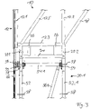
- a first exemplary embodiment of a rigid corner construction 10 for a keder roof hall is shown in a highly schematic form, to which 1 other components not shown in detail, such as roof lattice girders or system scaffolding, can be connected in order to form the supporting structure for the keder roof hall.
- the wall direction of the hall is indicated by the dash-dotted arrow RS, ie in this direction there is a wall-forming system framework construction below the rigid corner construction 10, on which the corner construction 10 is mounted or connected.
- the dot-dash arrow RG indicates the longitudinal direction of a lattice girder to which the Ecc construction 10 is connected to form the support structure, which is shown in 1 is not shown in detail.
- the angle W between the RS direction of the system framework and the RG direction of the lattice girder is in the range between 90° and up to 160° in practical embodiments.
- the rigid corner construction 10 has a first truss panel 12, which has an outer chord element 12.1 that carries an integrated keder rail and a parallel spaced inner chord element 12.2.
- first truss panel 12 is formed by a diagonal element 12.5 running from the bottom right and to the top left.
- the second truss panel 14 with an outer chord element 14.1 running on the upper side with an integrated piping rail, an inner chord element 14.2 arranged at a parallel distance on the inside, an end post element 14.3 and an inside post element 14.4.
- the second truss panel 14 also has a diagonal element 14.5, which runs in alignment with the diagonal element 12.5 of the first truss panel 12, with both diagonal elements 12.5, 14.5 forming a continuous diagonal.
- the first truss panel 12 is coupled to the second truss panel 14 as follows: First, a curved chord element 16 runs on the outside, which also has an integrated keder rail and forms a continuous keder rail profile with the outer chord elements 12.1, 14.1 of the first and second framework panels 12, 14.
- the upper post element 12.4 of the first truss panel 12 and the inside post element 14.4 of the second truss panel 14 are welded to the continuous diagonal in something its middle.
- a gusset plate 22 Opposite the center of the diagonal is a gusset plate 22 to the continuous diagonal - this is formed by the two Diagonal elements 12.5, 14.5 formed - welded to the inner chord element 12.2 of the first truss panel 12 and the inner chord element 14.2 of the second truss panel 14 is welded.
- a spacer post element 20 is welded to the gusset plate 22, which runs inwards and perpendicularly meets a stiffening diagonal 18, which is in the lower end area of the inner chord element 12.2 on the inside approximately at the level of the lower post element 12.3 and in the end area of the inner belt element 14.2 is welded on the inside approximately at the level of the inside post element 14.4.
- the stiffening diagonal 18 runs parallel to the two diagonal elements 12.5 and 14.5 and is arranged at a distance SB from the diagonal elements 12.5, 14.5, which essentially corresponds to the system width dimension SB of the system framework to be connected to the first truss panel 12 on the underside.
- the inner chord element 12.2 of the first truss panel 12 extends beyond the lower end of the lower post element 12.3, so that a downward-pointing, projecting, sleeve-shaped connection element 25.2 is formed.
- a further sleeve-shaped connection element 25.1 is welded to the lower post element 12.3 with a projecting underside at the system spacing SB, ie at a distance of the system width of the system framework to be connected.
- a lower terminal post element 24 is connected, which runs parallel to the lower post element 12.3 and is additionally connected to the lower post element 12.3 via two spacer elements 26 spaced apart from one another.
- This bearing construction with the lower end post element 24, the spacer elements 26 and connection elements 25.1, 25.2 results in a bearing construction with high rigidity and load-bearing capacity for connecting a system scaffolding with the system width dimension SB, such as Layher Allround Scaffolding or Layher SpeedyScaf.
- the distance from the outer chord element 14.1 to the inner chord element 14.2 of the second truss panel 14 is indicated by GH.
- This dimension GH essentially corresponds to the height of the lattice girder 60 to be connected for the roof construction.
- the connection itself is made in the upper chord area via a keder rail connection element 28 shown schematically, which is connected to the outer chord element 14.1 via connection screws 30, so that it can be easily connected by inserting the keder rail connection element 28 into the keder rail of the top chord of the lattice girder to be connected using additional connection screws secure connection of the lattice girder can be implemented with a seamless transition of the keder rails.
- FIG 2 shows the rigid corner connection construction 10 according to FIG 1 mirror-inverted with attached roof lattice support 60 (detail) and attached system scaffold 50 (detail). Identical components bear the same reference numbers and are not explained again.
- connection elements 25.1, 25.2 project downwards on the first truss panel 12 and are arranged in a system width SB, so that the rigid corner construction 10 can be attached from above to a system scaffolding 50.1, which in the exemplary embodiment is Layher Allround scaffolding system is formed. As a result, an "edge restraint" is practically formed.
- This scaffolding system 50.1 has two vertical bars 52.1 arranged in the system width SB, which are connected to one another in the upper end area via a cross bar 54.1. A diagonal 56.1 is used for stiffening in the transverse direction.
- the vertical bars 52.1 have rosettes 58 with wedge recesses, to which wedge heads 59 of the cross bar 54.1 or the diagonals 56.1 can be connected by driving in a movable wedge.
- the connection technology of the Layher Allround scaffolding system has been known and proven for decades.
- a keder rail profile 66 is present, which is connected to the rosettes 58 of the left vertical post 52 by means of a wedge head 59 via connection units 57.1.
- the connection is made in such a way that the keder rail profile 66 merges flush and seamlessly into the outer chord element 12.1 with keder rail of the first truss panel 12, so that a keder tarpaulin with keder rail profile can be drawn in continuously without any problems.
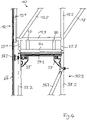
- connection area of the rigid corner construction to Layher Allround Scaffolding 50.1 is shown in detail. Identical components have the same reference numbers as in 2 and will not be explained again.
- the Layher SpeedyScaf System which has been tried and tested for years, consists of scaffolding frames with two parallel scaffolding standards 52.2, which are connected at the top with a crossbar 54.2, with a gusset plate 55 being welded in the inside corner area between the crossbar 54.2 and the scaffolding standards 52.2.
- the keder rail profile 66 which ends in the keder rail of the outer chord element 12.1 of the first truss panel 12, is connected to the left scaffolding post 52.2 in the area of the left gusset plate 55 via a connecting profile unit 57.2.
- the connecting elements 25.1, 25.2 are attached and connected to the scaffolding posts 52.2, which practically “clamps" the rigid corner construction to the system scaffolding 50.2.
- the upper or lower chord 60.1, 60.2 of the lattice girder 60 is connected to the outer chord element 14.1 and the inner chord element 14.2 of the second truss panel 14.
- the top chord 60.1 has a keder rail profile. The connection is made via the in 1 Keder rail connection element 28 shown in connection with the connection screws 30.
- the bottom chord 60.2 is connected to the inner chord element 14.2 of the second truss panel 14 via a corresponding connection element.
- the lattice girder 60 is “clamped at the edge” in the rigid corner construction 10 .
- Between the upper chord and lower chord 60.1, 60.2 of the lattice girder 60 there are posts running perpendicular thereto and connected, with rising and falling diagonals 60.3 running in between and connected to the chords.
- the supporting structure 100 formed by means of the rigid corner construction 10 for a keder roof hall is in the figure 5 (view) and 6 (perspective) shown schematically.
- System scaffolding 50.1 (Layher Allround Scaffolding System on the left) or 50.2 (Layher SpeedyScaf System on the right) is connected below each construction 10.
- a lattice girder 60 is connected to each corner structure 10 running inwards on the top side, with the lattice girders 60 being coupled to one another in the middle of the supporting structure 100 .
- the provision of an additional stiffening diagonal 18 enables a particularly stiff construction, by means of which large spans with high loads can be implemented.
- Both the lattice girder 60 and the system framework 50.1, 50.2 are thus clamped into the rigid corner construction.
- the outer circumferential keder profile is formed by the keder rail profile 66 on the frame 50.1, then the outer chord element 12.1, the curved chord element 16, the outer chord element 14.1, the upper chords 60.1 of the lattice girders, the outer chord element 14.1, the curved chord element 16, the outer chord element 12.1 and the keder rail profile 66 on the Scaffold 50 formed.
- additional stiffening elements are shown in the longitudinal direction L of the hall (double arrow in 4 ) shown. These are additional stiffening lattice girders 62 perpendicular to the plane of the sheet 2 run and to the post 60.4 in the longitudinal direction of adjacent lattice girders 60, to the inside post elements 14.4 of the second truss panel 14 and are connected to the upper post elements 12.4 of the first truss panel 12.
- the stiffening diagonals 18 of adjacent supporting structures are additionally stiffened in the longitudinal direction, ie transversely to the supporting structure, by lattice girders 60 running in the longitudinal direction L. Further stiffening elements in the transverse direction are the stiffening diagonals 64, which are connected between adjacent second truss panels 14 and adjacent first truss panels 12 of the rigid corner constructions 10 in the lower end region to the respective post elements 12.4, 14.4.
Landscapes
- Engineering & Computer Science (AREA)
- Architecture (AREA)
- Civil Engineering (AREA)
- Structural Engineering (AREA)
- Physics & Mathematics (AREA)
- Electromagnetism (AREA)
- Conveying And Assembling Of Building Elements In Situ (AREA)
- Joining Of Building Structures In Genera (AREA)
- Rod-Shaped Construction Members (AREA)
Description
- Die vorliegende Erfindung betrifft eine biegesteife Eckkonstruktion für eine Tragstruktur einer Kederdachhalle zum Anschluss eines Dachgitterträgers dieser Kederdachhalle in dessen Gitterträgerrichtung und zum Anschluss eines Systemgerüsts dieser Kederdachhalle in Wandrichtung, wobei die Eckkonstruktion ein in Wandrichtung verlaufendes erstes Fachwerkfeld und ein in Gitterträgerrichtung verlaufendes zweites Fachwerkfeld aufweist, und wobei das zweite Fachwerkfeld ein Außengurtelement mit einem Kederprofil und ein Innengurtelement aufweist und der Abstand des Außengurtelements und des Innengurtelements dem Abstand des Obergurts mit Kederschiene und dem Untergurt des Dachgitterträgers entspricht und das erste Fachwerkfeld unterseitig zwei Anschlusselemente aufweist, deren Systemabstand dem Systembreitenmaß eines Systemgerüsts, insbesondere Layher AllroundGerüst-System oder Layher Blitz Gerüst-System, oder einer Fahrbahnschienenkonstruktion entspricht.
- Die vorliegende Erfindung betrifft weiterhin eine Kederdachhallenkonstruktion mit mehreren in Längsrichtung parallel beabstandet angeordneten Tragstrukturen, wobei jede Tragstruktur zumindest zwei biegesteife Eckkonstruktionen aufweist.
- Aus der
EP 2 607 565 A1 ist ein als Kederdach ausgebildetes Schutzdach bekannt, das auf einem Systemstützgerüst gelagert ist. Dabei wird ein speziell ausgebildetes Auflager eingesetzt, das eine gelenkigen Auflagerung des jeweiligen Gitterträgers des Schutzdaches auf dem darunter angeordneten Stützgerüst ermöglicht. Der Obergurt des Gitterträgers weist ein Kederdachprofil auf, in den ein Kederprofil einer Plane eingezogen wird. Durch spezielle konstruktive Ausgestaltung der Lagerkonstruktion als ein gesondertes Auflager entsteht in aller Regel ein Spalt zwischen der Dachkante und dem darunter angeordneten Systemgerüst, der dann durch Zusatzbauteile relativ umständlich provisorisch geschlossen werden muss. Die Integration eines derartigen Daches in ein bestehendes Gerüst ist möglich, da das Auflager die üblichen Gerüstbreiten von 0,73 m oder 1,09 m (beispielsweise Layher AllroundGerüste oder Layher Blitz Gerüst-System) besitzt. Bei dieser bewährten Lösung, sind Dächer mit großer Spannweite realisierbar. - Die Anmelderin hat ein weiteres Kederdach auf den Markt gebracht, das eine biegesteife Eckkonstruktion aufweist, die das Problem des einfachen Schließens des Daches durch eine durchgehende Kederplane löst. Der Stützrahmen, die biegesteife Eckkonstruktion sowie der Gitterträger sind miteinander kompatibel und besitzen gleiche Höhen mit einem Kederprofil, damit eine Dachplane durch das Kederprofil ohne Versatz durch alle Bauteile eingezogen werden kann. Da der Stützrahmen jedoch nicht das Außenmaß der Gerüstbreite eines Systemgerüsts besitzt, kann dieser hierauf nicht montiert werden. Die Integration des Daches in ein vorhandenes beziehungsweise bestehendes Gerüstsystem ist daher nicht möglich. Aufgrund statischer Vorgaben sind nur Dächer mit kleinen Spannweiten umsetzbar.
- Des Weiteren sind Tragkonstruktionen für Kederdachhallen bekannt, die als polygonale Dächer bezeichnet werden. Diese bestehen im Wesentlichen aus mehreren Gitterträgerfirststücken, welche miteinander verbunden werden. Dachplanen können im Kederprofil (Obergurt) der Gitterträger durchgehend und ohne Versatz hindurch gezogen werden. Eine Montage auf ein Stützgerüst ist nicht möglich, da die Gitterträgerbreite und das Stützgerüstbreite nicht miteinander kompatibel sind.
- Aus der
DE 201 05 534 U1 als nächstliegender Stand der Technik ist eine biegesteife Eckkonstruktion mit den Merkmalen des Oberbegriffs des Anspruchs 1 bekannt. Dieses Dokument zeigt eine Schnellmontagehalle mit Fachwerkbindern, die jeweils über eine Fachwerkrahmeneckeinrichtung an eine jeweilige Stützeinrichtung angeschlossen sind. - Der vorliegenden Erfindung liegt das technische Problem beziehungsweise die Aufgabe zugrunde eine biegesteife Konstruktion für die Tragstruktur einer Kederdachhalle anzugeben, die wirtschaftlich hergestellt werden kann, eine schnelle Montage beziehungsweise Demontage ermöglicht, eine verminderte Anzahl von Bauteilen aufweist und mit der eine geschlossene Kederplanfläche der gesamten Hallenkonstruktion ohne größere Spalten beziehungsweise größeren Aufwand hergestellt werden kann sowie auch große Spannbreiten ermöglicht werden.
- Der vorliegenden Erfindung liegt weiterhin das technische Problem beziehungsweise die Aufgabe zugrunde, eine Kederdachhallenkonstruktion mit einer Tragstruktur anzugeben, bei der eine biegesteife Eckkonstruktion eingesetzt werden kann.
- Die erfindungsgemäße biegesteife Eckkonstruktion ist durch die Merkmale des unabhängigen Anspruchs 1 gegeben. Vorteilhafte Ausgestaltungen und Weiterbildungen sind Gegenstand der von dem unabhängigen Anspruch 1 direkt oder indirekt abhängigen Ansprüche 2 bis 8.
- Die erfindungsgemäße biegesteife Eckkonstruktion zeichnet sich demgemäß dadurch aus, dass das erste und zweite Fachwerkfeld jeweils ein Diagonalelement aufweist, die innerhalb der biegesteifen Eckkonstruktion eine durchgehende Diagonale bilden, die vom unteren Endbereich des Außengurtelements des ersten Fachwerkfeldes zum oberen Endbereich des Gurtelements des zweiten Fachwerkfeldes verläuft.
- Durch die geometrische Ausbildung der biegesteifen Eckkonstruktion wird das im Stand der Technik bekannte Auflager eingespart. Die Gitterträger können im Dachbereich problemlos und schnell an die Eckkonstruktion angeschlossen werden, ebenso an die im Wandbereich vorhandenen Stützgerüste. Als Stützgerüste werden vorzugsweise die Systeme Layher AllroundGerüst oder Layher Blitz Gerüst eingesetzt. Durch die erfindungsgemäße Ausgestaltung können Kosten durch einen schnellen Auf- und Abbau gespart werden, da ein Bauteil weniger im Vergleich zum Aufbau mit einem Auflager verbaut werden muss. Des Weiteren wird ermöglicht, dass das zu erstellende Dach ringsum, ohne größere Spalten und größeren zusätzlichen Montageaufwand durch einfache Art und Weise durch Einziehen einer umlaufenden Kederplane nahtlos geschlossen werden kann. Zudem ist durch die Art der Ausbildung des Anschlusses eine Art "Randeinspannung" des Gitterträgers und des Stützgerüsts in die biegesteife Eckkonstruktion gegeben, die eine große Spannweite ermöglicht.
- Eine besonders bevorzugte Ausgestaltung der erfindungsgemäßen biegesteifen Eckkonstruktion zeichnet sich dadurch aus, dass ein Anschlusselement durch den über das erste Fachwerkfeld unterseitig überstehenden Endbereich des Innengurtelements des Fachwerkfeldes gebildet wird und das gegenüberliegend beabstandet angeordnete Anschlusselement durch ein an das untere Pfostenelement des ersten Fachwerkfeldes unterseitig angeschlossene überstehende Anschlusshülse gebildet wird.
- Um eine geschlossene Kederdachplanenfläche zu erhalten, die in einfacher Art und Weise montiert werden kann, zeichnet sich eine besonders bevorzugte Ausgestaltung dadurch aus, dass das erste Fachwerkfeld ein Außengurtelement mit Kederschiene aufweist und zwischen dem Außengurtelement des zweiten Fachwerkfeldes und dem Außengurtelement des ersten Fachwerkfeldes ein gekrümmtes Außengurtelement jeweils durchgehend angeschlossen ist.
- Eine vorteilhafte Ausgestaltung, die eine einfache und schnelle Montage ermöglicht und eine hohe Lagesteifigkeit aufweist, zeichnet sich dadurch aus, dass zwischen den beiden Anschlusselementen ein parallel beabstandet zum unteren Pfostenelement des ersten Fachwerkfeldes unteres Abschlusspfostenelement angeschlossen ist.
- Gemäß einer besonders vorteilhaften Weiterbildung, die die Steifigkeit im Eckbereich weiterhin deutlich erhöht, zeichnet sich eine derartige Ausführungsvariante dadurch aus, dass zwischen dem unteren Endbereich des Innengurtelements des ersten Fachwerkfeldes und dem oberen Endbereich des Innengurtelements des zweiten Fachwerkfeldes innenseitig eine Aussteifungsdiagonale angeschlossen ist, die im Wesentlichen parallel beabstandet zu der durch die beiden Diagonalelemente des ersten beziehungsweise zweiten Fachwerkfeldes durchgehenden Diagonalen verläuft, insbesondere in einem parallelen Abstand, der im Wesentlichen der Systembreite des Systemgerüsts entspricht.
- Eine konstruktive Ausgestaltung, die eine einfache Herstellung ermöglicht und eine dauerhaft zuverlässige Funktionalität und hohe Tragfähigkeiten gewährleistet, zeichnet sich dadurch aus, dass im Wesentlichen in der Mitte der durchgehenden Diagonale ein Knotenblech angeschlossen ist, an das die Endbereiche der Innengurtelemente des ersten beziehungsweise des zweiten Fachwerkfeldes angeschlossen sind und ein Abstandspfostenelement angeschlossen ist, das gegenüberliegend an die innere Aussteifungsdiagonale, insbesondere rechtswinklig, angeschlossen ist.
- Bevorzugt sind sämtliche Anschlüsse geschweißt ausgebildet, was zu hohen Tragfähigkeiten und dauerhaft zuverlässigen Verbindungen mit hohen Festigkeiten führt.
- Da im Gerüstbau üblicherweise Rundrohrprofile eingesetzt werden, ist es besonders vorteilhaft, auch für die biegesteife Eckkonstruktion Radrohrprofile einzusetzen, die als Massenware zur Verfügung stehen.
- Die biegesteife Eckkonstruktion für ein Kederdach ermöglicht die Montage auf ein Stützgerüst ohne einen Spalt zwischen Traufe und Stützgerüst zu generieren. Somit kann das Dach mit bereits vorhandenen Standardbauteilen wie Kederschienenprofil und bekannten Adapter einfach und kostengünstig geschlossen werden. Die Integration auf ein bestehendes Gerüst wie beispielsweise Layher Allround oder Layher Blitz ist möglich, da die untere Breite der Eckkonstruktion dem Systemmaß des Blitzgerüsts entspricht. Aufgrund der statischen Gestaltung der biegesteifen Ecke, der vorhandenen Aussteifungsmöglichkeiten und der Bauhöhe sind große Spannweiten und Dachlasten realisierbar. Denkbar ist auch eine Montage einer derartigen biegesteifen Eckkonstruktion mit angeschlossenen Gitterträgern und/ oder Systemgerüstbauteilen auf einer Fahrschiene, um das Dach beziehungsweise die Hallenkonstruktion fahrbar zu gestalten.
- Die erfindungsgemäße Kederdachhallenkonstruktion ist durch die Merkmale des Anspruchs 9 gegeben.
- Die erfindungsgemäße Kederdachhallenkonstruktion mit mehreren in Längsrichtung beabstandeten Tragstrukturen zeichnet sich demgemäß dadurch aus, dass jede Tragstruktur zumindest zwei biegesteife Eckkonstruktionen, wie zuvor erfindungsgemäß beschrieben, zwischen den biegesteifen Eckkonstruktionen untereinander gekoppelte Dachgitterträger angeschlossen sind und unterseitig an jede biegesteife Eckkonstruktion ein Systemgerüst, insbesondere Layher AllroundGerüst oder Layher Blitz Gerüst angeschlossen ist, wobei an dem Systemgerüst außenseitig ein Kederschienenprofil angeschlossen ist, das fluchtend nahtlos auf das Kederschienenprofil des Außengurtelements des ersten Fachwerkfeldes übergeht.
- Weitere Ausführungsformen und Vorteile der Erfindung ergeben sich durch die in den Ansprüchen ferner aufgeführten Merkmale sowie durch die nachstehend angegebenen Ausführungsbeispiele. Die Merkmale der Ansprüche können in beliebiger Weise miteinander kombiniert werden, insoweit sie sich nicht offensichtlich gegenseitig ausschließen.
- Die Erfindung sowie vorteilhafte Ausführungsformen und Weiterbildungen derselben werden im Folgenden anhand der in der Zeichnung dargestellten Beispiele näher beschrieben und erläutert. Die der Beschreibung und der Zeichnung zu entnehmenden Merkmale können einzeln für sich oder zu mehreren in beliebiger Kombination erfindungsgemäß angewandt werden. Es zeigen:
- Fig. 1
- schematische Seitenansicht eines Ausführungsbeispiels einer biegesteifen Eckkonstruktion zum Anschluss eines Gitterträgers und eines Systemgerüsts,
- Fig. 2
- schematische Seitenansicht der biegesteifen Eckkonstruktion gemäß
Fig. 1 mit zusätzlich dargestellten angeschlossenem Gitterträger (Detail) und Systemgerüst (Detail) und Aussteifungskonstruktion in Querrichtung, - Fig. 3
- schematische Detailseitenansicht des Anschlussbereiches der biegesteifen Eckkonstruktion an ein Layher AllroundGerüst,
- Fig. 4
- schematische Detailseitenansicht des Anschlussbereiches der biegesteifen Eckkonstruktion an ein Layher Blitz Gerüst,
- Fig. 5
- schematische Seitenansicht einer Kederdachhallenkonstruktion unter Einsatz einer biegesteifen Eckkonstruktion gemäß
Fig. 1 beziehungsweiseFig. 2 , zwei gekoppelten Gitterträgern im Dachbereich und unterschiedlichen Systemgerüsten als Auflagerkonstruktion im Wandbereich, - Fig. 6
- schematische Perspektivansicht einer Kederdachhallenkonstruktion unter Einsatz einer biegesteifen Eckkonstruktion gemäß
Fig. 1 beziehungsweiseFig. 2 , zwei gekoppelten Gitterträgern im Dachbereich und unterschiedlichen Systemgerüsten als Auflagerkonstruktion im Wandbereich und - Fig. 7
- schematische Detailperspektivdarstellung einer Tragkonstruktion einer Kederdachhallenkonstruktion unter Einsatz von biegesteifen Eckkonstruktionen mit angeschlossenen Gitterträgern und Systemgerüsten gemäß
Fig. 5 und6 . - In
Fig. 1 ist stark schematisiert ein erstes Ausführungsbeispiel einer biegesteifen Eckkonstruktion 10 für eine Kederdachhalle dargestellt, an die inFig. 1 nicht näher dargestellte weitere Bauteile wie Dachgitterträger oder Systemgerüste anschließbar sind, um die Tragstruktur für die Kederdachhalle zu bilden. - Durch den strichpunktierten Pfeil RS ist die Wandrichtung der Halle angedeutet, das heißt in dieser Richtung ist unterhalb der biegesteifen Eckkonstruktion 10 eine wandbildende Systemgerüstkonstruktion vorhanden, auf der die Eckkonstruktion 10 gelagert beziehungsweise angeschlossen wird. Mit dem strichpunktiertem Pfeil RG ist die Längsrichtung eines Gitterträgers angedeutet, an dem die Ecckonstruktion 10 zur Bildung der Tragstruktur angeschlossen ist, was in
Fig. 1 nicht näher dargestellt ist. Der Winkel W zwischen der Richtung RS des Systemgerüst und der Richtung RG des Gitterträgers liegt in praktischen Ausführungsfällen im Bereich zwischen 90° und bis 160°. - In der Richtung RS weist die biegesteife Eckkonstruktion 10 ein erstes Fachwerkfeld 12 auf, das ein Außengurtelement 12.1, das eine integrierte Kederschiene trägt und ein parallel beabstandetes Innengurtelement 12.2 aufweist. Darüber hinaus ist im oberen Endbereich ein oberes Pfostenelement 12.4 und im unteren Endbereich des Fachwerkfeldes 12 ein unteres Pfostenelement 12.3 vorhanden, das jeweils das Außengurtelement 12.1 mit dem Innengurtelement 12.2 verbindet.
- Des Weiteren wird das erste Fachwerkfeld 12 durch eine von rechts unten und nach links oben verlaufendes Diagonalelement 12.5 gebildet.
- Ähnlich ist auch in der Richtung RG der Gitterträger ein zweites Fachwerkfeld 14 vorhanden mit einem oberseitig verlaufenden Außengurtelement 14.1 mit integrierter Kederschiene, innenseitig parallel beabstandet angeordnetem Innengurtelement 14.2, einem endseitigen Pfostenelement 14.3 und einem innenseitigen Pfostenelement 14.4. Auch das zweite Fachwerkfeld 14 weist ein Diagonalelement 14.5 auf, das in Flucht mit dem Diagonalelement 12.5 des ersten Fachwerkfelds 12 verläuft, wobei beide Diagonalelemente 12,.5, 14.5 eine durchgehende Diagonale bilden.
- Das erste Fachwerkfeld 12 ist mit dem zweiten Fachwerkfeld 14 wie folgt gekoppelt:
Zunächst verläuft außenseitig ein gekrümmtes Gurtelement 16, das ebenfalls eine integrierte Kederschiene aufweist und mit dem Außengurtelementen 12.1, 14.1 des ersten und zweiten Fachwerkfeldes 12, 14 ein durchgehendes Kederschienenprofil bildet. - Weiterhin ist das obere Pfostenelement 12.4 des ersten Fachwerkfeldes 12 und das innenseitige Pfostenelement 14.4 des zweiten Fachwerkfeldes 14 an die durchgehende Diagonale in etwas deren Mitte angeschweißt. Gegenüberliegend der Mitte der Diagonalen ist ein Knotenblech 22 an die durchgehende Diagonale - diese wird durch die beiden Diagonalelemente 12.5, 14.5 gebildet - angeschweißt, an den das Innengurtelement 12.2 des ersten Fachwerkfeldes 12 und das Innengurtelement 14.2 des zweiten Fachwerkfeldes 14 angeschweißt ist.
- Zwischen dem Anschluss der beiden Innengurtelemente 12.2, 14.2 ist an das Knotenblech 22 ein Abstandspfostenelement 20 angeschweißt, das nach innen verläuft und senkrecht auf eine Aussteifungsdiagonale 18 trifft, die im unteren Endbereich des Innengurtelements 12.2 innenseitig in etwa auf Höhe des unteren Pfostenelements 12.3 und im Endbereich des Innengurtelements 14.2 innenseitig in etwa auf Höhe des innenseitigen Pfostenelements 14.4 angeschweißt ist. Die Aussteifungsdiagonale 18 verläuft parallel zu den beiden Diagonalelementen 12.5 und 14.5 und ist in einem Abstand SB zu den Diagonalelementen 12.5, 14.5 angeordnet, der im Wesentlichen dem Systembreitenmaß SB des unterseitig an das erste Fachwerkfeld 12 anzuschließenden Systemsgerüsts entspricht.
- Das Innengurtelement 12.2 des ersten Fachwerkfeldes 12 ist über das untere Ende des unteren Pfostenelements 12.3 hinausgeführt, so dass ein nach unten weisendes überstehenden hülsenförmiges Anschlusselement 25.2 gebildet wird. Am gegenüberliegenden Endbereich des unteren Pfostenelements 12.3 ist im Systemabstand SB, das heißt im Abstand der Systembreite des anzuschließenden Systemgerüsts, ein weiteres hülsenförmiges Anschlusselement 25.1 unterseitig überstehend an das untere Pfostenelement 12.3 angeschweißt. Zwischen den beiden Anschlusselementen 25.1, 25.2 ist ein unterseitig und parallel zu dem unteren Pfostenelement 12.3 verlaufendes unteres Abschlusspfostenelement 24 angeschlossen, das zusätzlich über zwei untereinander beabstandete Abstandselemente 26 an das untere Pfostenelement 12.3 angeschlossen ist. Durch diese Lagerkonstruktion mit dem unteren Abschlusspfostenelement 24, den Abstandselementen 26 und Anschlusselementen 25.1, 25.2 entsteht eine Lagerkonstruktion mit hoher Steifigkeit und Tragfestigkeit zum Anschluss eines Systemgerüsts mit dem Systembreitenmaß SB wie beispielsweise einem Layher AllroundGerüst oder im Layher Blitz Gerüst.
- Der Abstand des Außengurtelements 14.1 zu dem Innengurtelement 14.2 des zweiten Fachwerkfeldes 14 ist mit GH angegeben. Dieses Maß GH entspricht im Wesentlichen der Höhe des anzuschließenden Gitterträgers 60 für die Dachkonstruktion. Der Anschluss selbst erfolgt im oberen Gurtbereich über ein schematisch dargestelltes Kederschienenanschlusselement 28, das über Anschlussschrauben 30 an dem Außengurtelement 14.1 angeschlossen ist, so dass in einfacher Art und Weise durch Einführen des Kederschienenanschlusselements 28 in die Kederschiene des anzuschließenden Obergurts des Gitterträgers unter Einsatz weiterer Anschlussschrauben ein sicherer Anschluss des Gitterträgers mit einem nahtlosen Übergang der Kederschienen umgesetzt werden kann.
-
Fig. 2 zeigt die biegesteife Eckverbindungskonstruktion 10 gemäßFig. 1 spiegelverkehrt bei angeschlossenem Dachgitterträger 60 (Detail) und angeschlossenem Systemgerüst 50 (Detail). Gleiche Bauteile tragen dasselbe Bezugszeichen und werden nicht nochmals erläutert. - Wie bereits oben beschrieben sind die beiden Anschlusselemente 25.1, 25.2 nach unten überstehend an dem ersten Fachwerkfeld 12 vorhanden und zwar angeordnet in einer Systembreite SB, so dass die biegesteife Eckkonstruktion 10 von oben her auf ein Systemgerüst 50.1 aufgesteckt werden kann, das im Ausführungsbeispiel als Layher AllroundGerüst-System ausgebildet ist. Dadurch wird praktisch eine "Randeinspannung" gebildet. Dieses Gerüstsystem 50.1 weist zwei in das Systembreite SB angeordnete Vertikalriegel 52.1 auf, die im oberen Endbereich über einen Querriegel 54.1 miteinander verbunden sind. Eine Diagonale 56.1 dient zur Aussteifung in Querrichtung. Zum Anschluss des Querriegels 54.1 und der Diagonalen 56.1 weisen die Vertikalriegel 52.1 Rosetten 58 mit Keilausnehmungen auf, an die Keilköpfe 59 des Querriegels 54.1 beziehungsweise der Diagonalen 56.1 durch Einschlagen eines beweglichen Keils angeschlossen werden können. Die Anschlusstechnik des Layher AllroundGerüst-Systems ist seit Jahrzehnten bekannt und bewährt.
- Gleichzeitig ist in
Fig. 2 zu erkennen, dass an der Außenseite des Systemgerüsts 50.1, das heißt auf der linken Seite vonFig. 2 , ein Kederschienenprofil 66 vorhanden ist, das über Anschlusseinheiten 57.1 an die Rosetten 58 des linken Vertikalstiels 52 mittels Keilkopf 59 angeschlossen ist. Der Anschluss erfolgt dabei so, dass das Kederschienenprofil 66 fluchtend und nahtlos in das Außengurtelement 12.1 mit Kederschiene des ersten Fachwerkfeldes 12 übergeht, so dass problemlos eine Kederplane mit Kederschienenprofil durchgängig eingezogen werden kann. - In
Fig. 3 ist der Anschlussbereich der biegesteifen Eckkonstruktion an ein Layher AllroundGerüst 50.1 im Detail dargestellt. Gleiche Bauteile tragen dasselbe Bezugszeichen wie inFig. 2 und werden nicht nochmals erläutert. - Die
Fig. 4 zeigt den Anschlussbereich der biegesteifen Eckkonstruktion an ein Layher Blitz Gerüst 50.2 im Detail. Das seit Jahren bekannte und bewährte Layher Blitz Gerüst-System besteht aus Gerüstrahmen mit zwei parallelen Gerüststielen 52.2, die oberseitig mit einem Querriegel 54.2 verbunden sind, wobei im Inneneckbereich zwischen Querriegel 54.2 und den Gerüststielen 52.2 ein Knotenblech 55 eingeschweißt ist. Auch hier ist das Kederschienenprofil 66, das in die Kederschiene des Außengurtelements 12.1 des ersten Fachwerkfeldes 12 mündet, über eine Anschlussprofileinheit 57.2 an den linken Gerüststiel 52.2 im Bereich des linken Knotenblechs 55 angeschlossen. Oberseitig sind auf den Gerüststielen 52.2 jeweils die Anschlusselemente 25.1, 25.2 aufgesteckt und verbunden, wodurch praktisch eine "Einspannung" der biegesteifen Eckkonstruktion an dem Systemgerüst 50.2 gegeben ist. - An das Außengurtelement 14.1 und das Innengurtelement 14.2 des zweiten Fachwerkfeldes 14 ist der Ober- beziehungsweise Untergurt 60.1, 60.2 des Gitterträgers 60 angeschlossen. Der Obergurt 60.1 weist ein Kederschienenprofil auf. Der Anschluss erfolgt dabei über das in
Fig. 1 dargestellte Kederschienenanschlusselement 28 in Verbindung mit den Anschlussschrauben 30. Der Untergurt 60.2 wird über ein entsprechendes Anschlusselement an das Innengurtelement 14.2 des zweiten Fachwerkfeldes 14 angeschlossen. Dadurch ist eine "Randeinspannung" des Gitterträgers 60 in die biegesteife Eckkonstruktion 10 gegeben. Zwischen dem Obergurt und Untergurt 60.1, 60.2 des Gitterträgers 60 sind senkrecht dazu verlaufende und angeschlossene Pfosten mit dazwischen verlaufenden und an die Gurte angeschlossenen steigenden und fallenden Diagonalen 60.3 vorhanden. - Die mittels der biegesteifen Eckkonstruktion 10 gebildete Tragstruktur 100 für eine Kederdachhalle ist in der
Fig. 5 (Ansicht) und 6 (Perspektive) schematisch dargestellt. Unterhalb jeder Konstruktion 10 ist das Systemgerüst 50.1 (links Layher AllroundGerüst-System) beziehungsweise 50.2 (rechts Layher Blitz Gerüst-System) angeschlossen. Oberseitig ist nach innen verlaufend an jede Ecckonstruktion 10 ein Gitterträger 60 angeschlossen, wobei die Gitterträger 60 in der Mitte der Tragstruktur 100 jeweils miteinander gekoppelt sind. Durch das Vorsehen einer zusätzlichen Aussteifungsdiagonale 18 wird eine besonders steife Konstruktion ermöglicht, mittels derer große Spannweiten mit hohen Traglasten umgesetzt werden können. Sowohl der Gitterträger 60 als auch das Systemgerüst 50.1, 50.2 sind somit in die biegesteife Eckkonstruktion eingespannt. Das außenseitige umlaufende Kederprofil wird durch das Kederschienenprofil 66 am Gerüst 50.1, anschließend das Außengurtelement 12.1, das gekrümmte Gurtelement 16, das Außengurtelement 14.1, die Obergurte 60.1 der Gitterträger, das Außengurtelement 14.1, das gekrümmte Gurtelement 16, das Außengurtelement 12.1 und das Kederschienenprofil 66 am Gerüst 50 gebildet. - In
Fig. 2 und inFig. 4 in einer Detailperspektive sind zusätzliche Aussteifungselemente in Hallenlängsrichtung L (Doppelpfeil inFig. 4 ) dargestellt. Dabei handelt es sich um zusätzliche Aussteifungsgitterträger 62, die senkrecht zur Blattebene vonFig. 2 verlaufen und an die Pfosten 60.4 in Längsrichtung benachbarter Gitterträger 60, an die innenseitigen Pfostenelemente 14.4 des zweiten Fachwerkfeldes 14 und an die oberen Pfostenelemente 12.4 des ersten Fachwerkfeldes 12, angeschlossen sind. Gleichzeitig sind die Aussteifungsdiagonalen 18 benachbarter Tragstrukturen zusätzlich durch in Längsrichtung L verlaufende Gitterträger 60 zusätzlich in Längsrichtung, das heißt quer zur Tragstruktur, ausgesteift. Weitere Aussteifungselemente in Querrichtung sind die Aussteifungsdiagonalen 64, die zwischen benachbarten zweiten Fachwerkfelder 14 und benachbarten ersten Fachwerkfelder 12 der biegesteifen Eckkonstruktionen 10 im unteren Endbereich angeschlossen an die jeweiligen Pfostenelemente 12.4, 14.4 sind.
Claims (9)
- Biegesteife Eckkonstruktion (10) für eine Tragstruktur (100) einer Kederdachhalle zum Anschluss eines Dachgitterträgers (60) dieser Kederdachhalle in dessen Gitterträgerrichtung (RG) und zum Anschluss eines Systemgerüsts (50.1, 50.2) dieser Kederdachhalle in Wandrichtung (RS), wobei die Eckkonstruktion ein in Wandrichtung (RS) verlaufendes erstes Fachwerkfeld (12) und ein in Gitterträgerrichtung (RG) verlaufendes zweites Fachwerkfeld (14) aufweist, und wobei- das zweite Fachwerkfeld (14) ein Außengurtelement (14.1) mit einem Kederprofil und ein Innengurtelement (14.2) aufweist und der Abstand des Außengurtelements (14.1) und des Innengurtelements (14.2) dem Abstand des Obergurts (60.1) mit Kederschiene und dem Untergurt (60.2) des Dachgitterträgers (60) entspricht und- das erste Fachwerkfeld (12) unterseitig zwei Anschlusselemente (25.1, 25.2) aufweist, deren Systemabstand dem Systembreitenmaß (SB) eines Systemgerüsts (50.1, 50.2), insbesondere Layher AllroundGerüst-System oder Layher Blitz Gerüst-System, oder einer Fahrbahnschienenkonstruktion entspricht,- dadurch gekennzeichnet, dass- das erste und zweite Fachwerkfeld (12, 14) jeweils ein Diagonalelement (12.5, 14.5) aufweist, die innerhalb der biegesteifen Eckkonstruktion eine durchgehende Diagonale bilden, die vom unteren Endbereich des Außengurtelements (12.1) des ersten Fachwerkfeldes (12) zum oberen Endbereich des Gurtelements (14.1) des zweiten Fachwerkfeldes (14) verläuft.
- Biegesteife Eckkonstruktion nach Anspruch 1,- dadurch gekennzeichnet, dass- ein Anschlusselement (25.2) durch den über das erste Fachwerkfeld (12) unterseitig überstehenden Endbereich des Innengurtelements (12.2) des Fachwerkfeldes (12) gebildet wird und das gegenüberliegend beabstandet (SB) angeordnete Anschlusselement (25.1) durch ein an das untere Pfostenelement (12.3) des ersten Fachwerkfeldes (12) unterseitig angeschlossene überstehende Anschlusshülse gebildet wird.
- Biegesteife Eckkonstruktion nach Anspruch 1 oder 2,- dadurch gekennzeichnet, dass- zwischen den beiden Anschlusselementen (25.1, 25.2) ein parallel beabstandet zum unteren Pfostenelement (12.3) des ersten Fachwerkfeldes (12) unteres Abschlusspfostenelement (24) angeschlossen ist.
- Biegesteife Eckkonstruktion nach einem oder mehreren der vorstehenden Ansprüche,- dadurch gekennzeichnet, dass- das erste Fachwerkfeld (12) ein Außengurtelement (12.1) mit Kederschiene aufweist und zwischen dem Außengurtelement (14.1) des zweiten Fachwerkfeldes (14) und dem Außengurtelement (12.1) des ersten Fachwerkfeldes (12) ein gekrümmtes Außengurtelement (16) jeweils durchgehend angeschlossen ist.
- Biegesteife Eckkonstruktion nach einem oder mehreren der vorstehenden Ansprüche,- dadurch gekennzeichnet, dass- zwischen dem unteren Endbereich des Innengurtelements (12.2) des ersten Fachwerkfeldes (12) und dem oberen Endbereich des Innengurtelements (14.2) des zweiten Fachwerkfeldes (14) innenseitig eine Aussteifungsdiagonale (18) angeschlossen ist, die im Wesentlichen parallel beabstandet zu der durch die beiden Diagonalelemente (12.5, 14.5) des ersten beziehungsweise zweiten Fachwerkfeldes (12, 14) durchgehenden Diagonalen verläuft, insbesondere in einem parallelen Abstand, der im Wesentlichen der Systembreite (SB) des Systemgerüsts (50) entspricht.
- Biegesteife Eckkonstruktion nach Anspruch 5,- dadurch gekennzeichnet, dass- im Wesentlichen in der Mitte der durchgehenden Diagonale ein Knotenblech (22) angeschlossen ist, an das die Endbereiche der Innengurtelemente (12.2, 14.2) des ersten beziehungsweise des zweiten Fachwerkfeldes (12, 14) angeschlossen sind und ein Abstandspfostenelement (20) angeschlossen ist, das gegenüberliegend an die innere Aussteifungsdiagonale (18), insbesondere rechtwinklig, angeschlossen ist.
- Biegesteife Eckkonstruktion nach einem oder mehreren der vorstehenden Ansprüche,- dadurch gekennzeichnet, dass- sämtliche Anschlüsse geschweißt ausgebildet sind.
- Biegesteife Eckkonstruktion nach einem oder mehreren der vorstehenden Ansprüche,- dadurch gekennzeichnet, dass- sämtliche Profile, bis auf die Außengurtelemente (12.1, 14.1) als Rundrohrprofile ausgebildet sind.
- Kederdachhallenkonstruktion mit mehreren in Längsrichtung (L) parallel beabstandeten Tragstrukturen (100), wobei jede Tragstruktur (100) zumindest zwei biegesteife Eckkonstruktionen (10) nach einem oder mehreren der vorstehenden Ansprüche 1 bis 8 aufweist, zwischen den biegesteifen Eckkonstruktionen (10) untereinander gekoppelte Dachgitterträger (60) angeschlossen sind und unterseitig an jede biegesteife Eckkonstruktion (10) ein Systemgerüst, insbesondere Layher AllroundGerüst oder Layher Blitz Gerüst angeschlossen ist, wobei an dem Systemgerüst außenseitig ein Kederschienenprofil (66) angeschlossen ist, das fluchtend nahtlos auf das Kederschienenprofil des Außengurtelements (12.1) des ersten Fachwerkfeldes (12) übergeht.
Applications Claiming Priority (2)
| Application Number | Priority Date | Filing Date | Title |
|---|---|---|---|
| DE102016004074.2A DE102016004074A1 (de) | 2016-04-08 | 2016-04-08 | Biegesteife Eckkonstruktion für die Tragstruktur einer Kederdachhalle |
| PCT/DE2017/000087 WO2017174052A2 (de) | 2016-04-08 | 2017-04-03 | Biegesteife eckkonstruktion für die tragstruktur einer kederdachhalle |
Publications (2)
| Publication Number | Publication Date |
|---|---|
| EP3440277A2 EP3440277A2 (de) | 2019-02-13 |
| EP3440277B1 true EP3440277B1 (de) | 2022-09-14 |
Family
ID=58744934
Family Applications (1)
| Application Number | Title | Priority Date | Filing Date |
|---|---|---|---|
| EP17724730.1A Active EP3440277B1 (de) | 2016-04-08 | 2017-04-03 | Biegesteife eckkonstruktion für die tragstruktur einer kederdachhalle |
Country Status (3)
| Country | Link |
|---|---|
| EP (1) | EP3440277B1 (de) |
| DE (2) | DE102016004074A1 (de) |
| WO (1) | WO2017174052A2 (de) |
Families Citing this family (2)
| Publication number | Priority date | Publication date | Assignee | Title |
|---|---|---|---|---|
| CN116575583B (zh) * | 2023-07-11 | 2023-09-22 | 北京建工四建工程建设有限公司 | 一种连续超长悬挑钢结构带及其安装方法 |
| GB2634509B (en) * | 2023-10-09 | 2026-01-21 | Apollo Cradles Ltd | Keder tube scaffold assembly |
Citations (2)
| Publication number | Priority date | Publication date | Assignee | Title |
|---|---|---|---|---|
| DE20105534U1 (de) * | 2001-03-28 | 2001-09-27 | Wilhelm Layher Vermögensverwaltungs-GmbH, 74363 Güglingen | Schnell-Montage-Halle |
| EP3179014A1 (de) * | 2015-12-09 | 2017-06-14 | ALFIX GmbH | Fachwerkdachbinder mit eckteil und eine diesen verwendende dachanordnung |
Family Cites Families (4)
| Publication number | Priority date | Publication date | Assignee | Title |
|---|---|---|---|---|
| US5269106A (en) * | 1991-11-20 | 1993-12-14 | Fast Truss, Inc. | Modular building structure |
| DE19526197A1 (de) * | 1995-07-18 | 1997-01-23 | Waco Wackerbauer & Co | Dachanordnung mit Planen und einer Mehrzahl die Planen zwischen sich aufnehmender Gitterträger sowie Gitterträger für eine derartige Dachanordnung |
| ES2246548T3 (es) * | 1999-03-12 | 2006-02-16 | Wilhelm Layher Vermogensverwaltungs-Gmbh | Tejado de nave de montaje rapido. |
| DE102011121782A1 (de) | 2011-12-21 | 2013-06-27 | Wilhelm Layher Verwaltungs-Gmbh | Kederdachfirstträger und Kederdachträgereinrichtung |
-
2016
- 2016-04-08 DE DE102016004074.2A patent/DE102016004074A1/de not_active Withdrawn
-
2017
- 2017-04-03 DE DE112017001857.9T patent/DE112017001857A5/de not_active Withdrawn
- 2017-04-03 WO PCT/DE2017/000087 patent/WO2017174052A2/de not_active Ceased
- 2017-04-03 EP EP17724730.1A patent/EP3440277B1/de active Active
Patent Citations (2)
| Publication number | Priority date | Publication date | Assignee | Title |
|---|---|---|---|---|
| DE20105534U1 (de) * | 2001-03-28 | 2001-09-27 | Wilhelm Layher Vermögensverwaltungs-GmbH, 74363 Güglingen | Schnell-Montage-Halle |
| EP3179014A1 (de) * | 2015-12-09 | 2017-06-14 | ALFIX GmbH | Fachwerkdachbinder mit eckteil und eine diesen verwendende dachanordnung |
Also Published As
| Publication number | Publication date |
|---|---|
| EP3440277A2 (de) | 2019-02-13 |
| WO2017174052A2 (de) | 2017-10-12 |
| WO2017174052A3 (de) | 2017-12-14 |
| DE112017001857A5 (de) | 2019-01-03 |
| DE102016004074A1 (de) | 2017-10-12 |
Similar Documents
| Publication | Publication Date | Title |
|---|---|---|
| EP3417121B1 (de) | Fachwerktragsystem zum aufbau einer tragkonstruktion | |
| WO2006026980A1 (de) | Anordnung zur stabilisierung von stützkonstruktionen | |
| DE202022102656U1 (de) | Trägerstruktur zur Konstruktion der Bahnsteigüberdachung | |
| EP3147424B1 (de) | Gitterträger und gitterträgersystem, insbesondere zum universellen einsatz innerhalb eines bekannten arbeits- und schutzgerüsts | |
| EP3440277B1 (de) | Biegesteife eckkonstruktion für die tragstruktur einer kederdachhalle | |
| DE102007047919A1 (de) | Traggerüst und Verfahren zur Demontage und Transport | |
| EP2607565B1 (de) | Kederdachfirstträger und Kederdachträgereinrichtung | |
| DE10130866A1 (de) | Bauelement zur Wärmedämmung | |
| EP4551783A1 (de) | Schalungstischelement, schalungstisch und verfahren zum aufbau einer deckenschalung | |
| EP0814212A2 (de) | Tragrahmenvorrichtung | |
| DE20105534U1 (de) | Schnell-Montage-Halle | |
| DE2556365A1 (de) | Stuetzenturm | |
| DE3117628A1 (de) | Dachaussteifung, insbesondere fuer ein sattelfoermiges binderdach | |
| EP3784847B1 (de) | Verfahren zum verankern einer gerüstkonstruktion an einer eingerüsteten vorrichtung und vorrichtung zur durchführung eines derartigen verfahrens | |
| DE19607952A1 (de) | Traggerüst zur Stützung von Massivbauwerken | |
| EP1288392B1 (de) | Unterstützungskonstruktion für einen Systemträger einer Bühnen-, Podium-, Gerüstkonstruktion oder dergleichen | |
| AT522691B1 (de) | Gründung für ein Gebäude | |
| DE2138483C3 (de) | Traggerüst mit Stielen und Riegeln aus vorgefertigten Stahlbetonelementen | |
| DE202022002594U1 (de) | Winkelgitterträger | |
| DE29617977U1 (de) | Traggerüst zur Stützung von Massivbauwerken | |
| DE202005006228U1 (de) | Dachkonstruktion für Gebäude, insbesondere für Industriegebäude mit großen Spannweiten | |
| DE102022210828A1 (de) | Verfahren zum Aufbau eines Traggerüsts und Traggerüst | |
| DE915977C (de) | Stuetze fuer Kranbahnen, insbesondere zur Verwendung in Werkshallen | |
| CH695386A5 (de) | Systemträger für Schalungen und Lehrgerüste für Schwerlastanwendung im Betonbau. | |
| DE202009006181U1 (de) | Tragwerk |
Legal Events
| Date | Code | Title | Description |
|---|---|---|---|
| STAA | Information on the status of an ep patent application or granted ep patent |
Free format text: STATUS: UNKNOWN |
|
| STAA | Information on the status of an ep patent application or granted ep patent |
Free format text: STATUS: THE INTERNATIONAL PUBLICATION HAS BEEN MADE |
|
| PUAI | Public reference made under article 153(3) epc to a published international application that has entered the european phase |
Free format text: ORIGINAL CODE: 0009012 |
|
| STAA | Information on the status of an ep patent application or granted ep patent |
Free format text: STATUS: REQUEST FOR EXAMINATION WAS MADE |
|
| 17P | Request for examination filed |
Effective date: 20180808 |
|
| AK | Designated contracting states |
Kind code of ref document: A2 Designated state(s): AL AT BE BG CH CY CZ DE DK EE ES FI FR GB GR HR HU IE IS IT LI LT LU LV MC MK MT NL NO PL PT RO RS SE SI SK SM TR |
|
| AX | Request for extension of the european patent |
Extension state: BA ME |
|
| DAV | Request for validation of the european patent (deleted) | ||
| DAX | Request for extension of the european patent (deleted) | ||
| STAA | Information on the status of an ep patent application or granted ep patent |
Free format text: STATUS: EXAMINATION IS IN PROGRESS |
|
| 17Q | First examination report despatched |
Effective date: 20210611 |
|
| GRAP | Despatch of communication of intention to grant a patent |
Free format text: ORIGINAL CODE: EPIDOSNIGR1 |
|
| STAA | Information on the status of an ep patent application or granted ep patent |
Free format text: STATUS: GRANT OF PATENT IS INTENDED |
|
| INTG | Intention to grant announced |
Effective date: 20220422 |
|
| GRAS | Grant fee paid |
Free format text: ORIGINAL CODE: EPIDOSNIGR3 |
|
| GRAA | (expected) grant |
Free format text: ORIGINAL CODE: 0009210 |
|
| STAA | Information on the status of an ep patent application or granted ep patent |
Free format text: STATUS: THE PATENT HAS BEEN GRANTED |
|
| AK | Designated contracting states |
Kind code of ref document: B1 Designated state(s): AL AT BE BG CH CY CZ DE DK EE ES FI FR GB GR HR HU IE IS IT LI LT LU LV MC MK MT NL NO PL PT RO RS SE SI SK SM TR |
|
| REG | Reference to a national code |
Ref country code: GB Ref legal event code: FG4D Free format text: NOT ENGLISH |
|
| REG | Reference to a national code |
Ref country code: CH Ref legal event code: EP |
|
| REG | Reference to a national code |
Ref country code: DE Ref legal event code: R096 Ref document number: 502017013804 Country of ref document: DE |
|
| REG | Reference to a national code |
Ref country code: IE Ref legal event code: FG4D Free format text: LANGUAGE OF EP DOCUMENT: GERMAN |
|
| REG | Reference to a national code |
Ref country code: AT Ref legal event code: REF Ref document number: 1518779 Country of ref document: AT Kind code of ref document: T Effective date: 20221015 |
|
| REG | Reference to a national code |
Ref country code: SE Ref legal event code: TRGR |
|
| REG | Reference to a national code |
Ref country code: NL Ref legal event code: FP |
|
| REG | Reference to a national code |
Ref country code: LT Ref legal event code: MG9D |
|
| PG25 | Lapsed in a contracting state [announced via postgrant information from national office to epo] |
Ref country code: RS Free format text: LAPSE BECAUSE OF FAILURE TO SUBMIT A TRANSLATION OF THE DESCRIPTION OR TO PAY THE FEE WITHIN THE PRESCRIBED TIME-LIMIT Effective date: 20220914 Ref country code: NO Free format text: LAPSE BECAUSE OF FAILURE TO SUBMIT A TRANSLATION OF THE DESCRIPTION OR TO PAY THE FEE WITHIN THE PRESCRIBED TIME-LIMIT Effective date: 20221214 Ref country code: LV Free format text: LAPSE BECAUSE OF FAILURE TO SUBMIT A TRANSLATION OF THE DESCRIPTION OR TO PAY THE FEE WITHIN THE PRESCRIBED TIME-LIMIT Effective date: 20220914 Ref country code: LT Free format text: LAPSE BECAUSE OF FAILURE TO SUBMIT A TRANSLATION OF THE DESCRIPTION OR TO PAY THE FEE WITHIN THE PRESCRIBED TIME-LIMIT Effective date: 20220914 Ref country code: FI Free format text: LAPSE BECAUSE OF FAILURE TO SUBMIT A TRANSLATION OF THE DESCRIPTION OR TO PAY THE FEE WITHIN THE PRESCRIBED TIME-LIMIT Effective date: 20220914 |
|
| PG25 | Lapsed in a contracting state [announced via postgrant information from national office to epo] |
Ref country code: HR Free format text: LAPSE BECAUSE OF FAILURE TO SUBMIT A TRANSLATION OF THE DESCRIPTION OR TO PAY THE FEE WITHIN THE PRESCRIBED TIME-LIMIT Effective date: 20220914 Ref country code: GR Free format text: LAPSE BECAUSE OF FAILURE TO SUBMIT A TRANSLATION OF THE DESCRIPTION OR TO PAY THE FEE WITHIN THE PRESCRIBED TIME-LIMIT Effective date: 20221215 |
|
| PG25 | Lapsed in a contracting state [announced via postgrant information from national office to epo] |
Ref country code: SM Free format text: LAPSE BECAUSE OF FAILURE TO SUBMIT A TRANSLATION OF THE DESCRIPTION OR TO PAY THE FEE WITHIN THE PRESCRIBED TIME-LIMIT Effective date: 20220914 Ref country code: RO Free format text: LAPSE BECAUSE OF FAILURE TO SUBMIT A TRANSLATION OF THE DESCRIPTION OR TO PAY THE FEE WITHIN THE PRESCRIBED TIME-LIMIT Effective date: 20220914 Ref country code: PT Free format text: LAPSE BECAUSE OF FAILURE TO SUBMIT A TRANSLATION OF THE DESCRIPTION OR TO PAY THE FEE WITHIN THE PRESCRIBED TIME-LIMIT Effective date: 20230116 Ref country code: ES Free format text: LAPSE BECAUSE OF FAILURE TO SUBMIT A TRANSLATION OF THE DESCRIPTION OR TO PAY THE FEE WITHIN THE PRESCRIBED TIME-LIMIT Effective date: 20220914 Ref country code: CZ Free format text: LAPSE BECAUSE OF FAILURE TO SUBMIT A TRANSLATION OF THE DESCRIPTION OR TO PAY THE FEE WITHIN THE PRESCRIBED TIME-LIMIT Effective date: 20220914 |
|
| PG25 | Lapsed in a contracting state [announced via postgrant information from national office to epo] |
Ref country code: SK Free format text: LAPSE BECAUSE OF FAILURE TO SUBMIT A TRANSLATION OF THE DESCRIPTION OR TO PAY THE FEE WITHIN THE PRESCRIBED TIME-LIMIT Effective date: 20220914 Ref country code: PL Free format text: LAPSE BECAUSE OF FAILURE TO SUBMIT A TRANSLATION OF THE DESCRIPTION OR TO PAY THE FEE WITHIN THE PRESCRIBED TIME-LIMIT Effective date: 20220914 Ref country code: IS Free format text: LAPSE BECAUSE OF FAILURE TO SUBMIT A TRANSLATION OF THE DESCRIPTION OR TO PAY THE FEE WITHIN THE PRESCRIBED TIME-LIMIT Effective date: 20230114 Ref country code: EE Free format text: LAPSE BECAUSE OF FAILURE TO SUBMIT A TRANSLATION OF THE DESCRIPTION OR TO PAY THE FEE WITHIN THE PRESCRIBED TIME-LIMIT Effective date: 20220914 |
|
| REG | Reference to a national code |
Ref country code: DE Ref legal event code: R097 Ref document number: 502017013804 Country of ref document: DE |
|
| P01 | Opt-out of the competence of the unified patent court (upc) registered |
Effective date: 20230516 |
|
| PG25 | Lapsed in a contracting state [announced via postgrant information from national office to epo] |
Ref country code: AL Free format text: LAPSE BECAUSE OF FAILURE TO SUBMIT A TRANSLATION OF THE DESCRIPTION OR TO PAY THE FEE WITHIN THE PRESCRIBED TIME-LIMIT Effective date: 20220914 |
|
| PLBE | No opposition filed within time limit |
Free format text: ORIGINAL CODE: 0009261 |
|
| STAA | Information on the status of an ep patent application or granted ep patent |
Free format text: STATUS: NO OPPOSITION FILED WITHIN TIME LIMIT |
|
| PG25 | Lapsed in a contracting state [announced via postgrant information from national office to epo] |
Ref country code: DK Free format text: LAPSE BECAUSE OF FAILURE TO SUBMIT A TRANSLATION OF THE DESCRIPTION OR TO PAY THE FEE WITHIN THE PRESCRIBED TIME-LIMIT Effective date: 20220914 |
|
| 26N | No opposition filed |
Effective date: 20230615 |
|
| PG25 | Lapsed in a contracting state [announced via postgrant information from national office to epo] |
Ref country code: SI Free format text: LAPSE BECAUSE OF FAILURE TO SUBMIT A TRANSLATION OF THE DESCRIPTION OR TO PAY THE FEE WITHIN THE PRESCRIBED TIME-LIMIT Effective date: 20220914 |
|
| REG | Reference to a national code |
Ref country code: CH Ref legal event code: PL |
|
| REG | Reference to a national code |
Ref country code: DE Ref legal event code: R082 Ref document number: 502017013804 Country of ref document: DE Representative=s name: GLEIM PETRI PATENT- UND RECHTSANWALTSPARTNERSC, DE |
|
| PG25 | Lapsed in a contracting state [announced via postgrant information from national office to epo] |
Ref country code: LU Free format text: LAPSE BECAUSE OF NON-PAYMENT OF DUE FEES Effective date: 20230403 |
|
| REG | Reference to a national code |
Ref country code: BE Ref legal event code: MM Effective date: 20230430 |
|
| PG25 | Lapsed in a contracting state [announced via postgrant information from national office to epo] |
Ref country code: MC Free format text: LAPSE BECAUSE OF FAILURE TO SUBMIT A TRANSLATION OF THE DESCRIPTION OR TO PAY THE FEE WITHIN THE PRESCRIBED TIME-LIMIT Effective date: 20220914 |
|
| PG25 | Lapsed in a contracting state [announced via postgrant information from national office to epo] |
Ref country code: MC Free format text: LAPSE BECAUSE OF FAILURE TO SUBMIT A TRANSLATION OF THE DESCRIPTION OR TO PAY THE FEE WITHIN THE PRESCRIBED TIME-LIMIT Effective date: 20220914 Ref country code: LI Free format text: LAPSE BECAUSE OF NON-PAYMENT OF DUE FEES Effective date: 20230430 Ref country code: FR Free format text: LAPSE BECAUSE OF NON-PAYMENT OF DUE FEES Effective date: 20230430 Ref country code: CH Free format text: LAPSE BECAUSE OF NON-PAYMENT OF DUE FEES Effective date: 20230430 |
|
| REG | Reference to a national code |
Ref country code: IE Ref legal event code: MM4A |
|
| PG25 | Lapsed in a contracting state [announced via postgrant information from national office to epo] |
Ref country code: BE Free format text: LAPSE BECAUSE OF NON-PAYMENT OF DUE FEES Effective date: 20230430 |
|
| PG25 | Lapsed in a contracting state [announced via postgrant information from national office to epo] |
Ref country code: IE Free format text: LAPSE BECAUSE OF NON-PAYMENT OF DUE FEES Effective date: 20230403 |
|
| PG25 | Lapsed in a contracting state [announced via postgrant information from national office to epo] |
Ref country code: IE Free format text: LAPSE BECAUSE OF NON-PAYMENT OF DUE FEES Effective date: 20230403 |
|
| PG25 | Lapsed in a contracting state [announced via postgrant information from national office to epo] |
Ref country code: IT Free format text: LAPSE BECAUSE OF FAILURE TO SUBMIT A TRANSLATION OF THE DESCRIPTION OR TO PAY THE FEE WITHIN THE PRESCRIBED TIME-LIMIT Effective date: 20220914 |
|
| REG | Reference to a national code |
Ref country code: AT Ref legal event code: MM01 Ref document number: 1518779 Country of ref document: AT Kind code of ref document: T Effective date: 20230403 |
|
| PG25 | Lapsed in a contracting state [announced via postgrant information from national office to epo] |
Ref country code: AT Free format text: LAPSE BECAUSE OF NON-PAYMENT OF DUE FEES Effective date: 20230403 |
|
| PG25 | Lapsed in a contracting state [announced via postgrant information from national office to epo] |
Ref country code: AT Free format text: LAPSE BECAUSE OF NON-PAYMENT OF DUE FEES Effective date: 20230403 |
|
| PG25 | Lapsed in a contracting state [announced via postgrant information from national office to epo] |
Ref country code: BG Free format text: LAPSE BECAUSE OF FAILURE TO SUBMIT A TRANSLATION OF THE DESCRIPTION OR TO PAY THE FEE WITHIN THE PRESCRIBED TIME-LIMIT Effective date: 20220914 |
|
| PG25 | Lapsed in a contracting state [announced via postgrant information from national office to epo] |
Ref country code: BG Free format text: LAPSE BECAUSE OF FAILURE TO SUBMIT A TRANSLATION OF THE DESCRIPTION OR TO PAY THE FEE WITHIN THE PRESCRIBED TIME-LIMIT Effective date: 20220914 |
|
| PGFP | Annual fee paid to national office [announced via postgrant information from national office to epo] |
Ref country code: NL Payment date: 20250422 Year of fee payment: 9 |
|
| PGFP | Annual fee paid to national office [announced via postgrant information from national office to epo] |
Ref country code: DE Payment date: 20250428 Year of fee payment: 9 |
|
| PG25 | Lapsed in a contracting state [announced via postgrant information from national office to epo] |
Ref country code: CY Free format text: LAPSE BECAUSE OF FAILURE TO SUBMIT A TRANSLATION OF THE DESCRIPTION OR TO PAY THE FEE WITHIN THE PRESCRIBED TIME-LIMIT; INVALID AB INITIO Effective date: 20170403 |
|
| PGFP | Annual fee paid to national office [announced via postgrant information from national office to epo] |
Ref country code: SE Payment date: 20250423 Year of fee payment: 9 |
|
| PG25 | Lapsed in a contracting state [announced via postgrant information from national office to epo] |
Ref country code: HU Free format text: LAPSE BECAUSE OF FAILURE TO SUBMIT A TRANSLATION OF THE DESCRIPTION OR TO PAY THE FEE WITHIN THE PRESCRIBED TIME-LIMIT; INVALID AB INITIO Effective date: 20170403 |
|
| PG25 | Lapsed in a contracting state [announced via postgrant information from national office to epo] |
Ref country code: TR Free format text: LAPSE BECAUSE OF FAILURE TO SUBMIT A TRANSLATION OF THE DESCRIPTION OR TO PAY THE FEE WITHIN THE PRESCRIBED TIME-LIMIT Effective date: 20220914 |
|
| PGFP | Annual fee paid to national office [announced via postgrant information from national office to epo] |
Ref country code: GB Payment date: 20260324 Year of fee payment: 10 |