EP3440920B1 - Diviseur extérieur d'épis - Google Patents
Diviseur extérieur d'épis Download PDFInfo
- Publication number
- EP3440920B1 EP3440920B1 EP18169147.8A EP18169147A EP3440920B1 EP 3440920 B1 EP3440920 B1 EP 3440920B1 EP 18169147 A EP18169147 A EP 18169147A EP 3440920 B1 EP3440920 B1 EP 3440920B1
- Authority
- EP
- European Patent Office
- Prior art keywords
- cover element
- base body
- outer stalk
- divider
- stalk divider
- Prior art date
- Legal status (The legal status is an assumption and is not a legal conclusion. Google has not performed a legal analysis and makes no representation as to the accuracy of the status listed.)
- Active
Links
Images


Classifications
-
- A—HUMAN NECESSITIES
- A01—AGRICULTURE; FORESTRY; ANIMAL HUSBANDRY; HUNTING; TRAPPING; FISHING
- A01D—HARVESTING; MOWING
- A01D45/00—Harvesting of standing crops
- A01D45/02—Harvesting of standing crops of maize, i.e. kernel harvesting
-
- A—HUMAN NECESSITIES
- A01—AGRICULTURE; FORESTRY; ANIMAL HUSBANDRY; HUNTING; TRAPPING; FISHING
- A01D—HARVESTING; MOWING
- A01D63/00—Outside dividers
- A01D63/04—Non-rotating dividers
-
- A—HUMAN NECESSITIES
- A01—AGRICULTURE; FORESTRY; ANIMAL HUSBANDRY; HUNTING; TRAPPING; FISHING
- A01D—HARVESTING; MOWING
- A01D41/00—Combines, i.e. harvesters or mowers combined with threshing devices
- A01D41/12—Details of combines
- A01D41/14—Mowing tables
-
- A—HUMAN NECESSITIES
- A01—AGRICULTURE; FORESTRY; ANIMAL HUSBANDRY; HUNTING; TRAPPING; FISHING
- A01D—HARVESTING; MOWING
- A01D43/00—Mowers combined with apparatus performing additional operations while mowing
- A01D43/08—Mowers combined with apparatus performing additional operations while mowing with means for cutting up the mown crop, e.g. forage harvesters
- A01D43/081—Mowers combined with apparatus performing additional operations while mowing with means for cutting up the mown crop, e.g. forage harvesters specially adapted for ensilage of maize
-
- A—HUMAN NECESSITIES
- A01—AGRICULTURE; FORESTRY; ANIMAL HUSBANDRY; HUNTING; TRAPPING; FISHING
- A01D—HARVESTING; MOWING
- A01D57/00—Delivering mechanisms for harvesters or mowers
- A01D57/22—Delivering mechanisms for harvesters or mowers for standing stalks
-
- A—HUMAN NECESSITIES
- A01—AGRICULTURE; FORESTRY; ANIMAL HUSBANDRY; HUNTING; TRAPPING; FISHING
- A01D—HARVESTING; MOWING
- A01D91/00—Methods for harvesting agricultural products
- A01D91/04—Products growing above the soil
-
- A—HUMAN NECESSITIES
- A01—AGRICULTURE; FORESTRY; ANIMAL HUSBANDRY; HUNTING; TRAPPING; FISHING
- A01D—HARVESTING; MOWING
- A01D45/00—Harvesting of standing crops
- A01D45/02—Harvesting of standing crops of maize, i.e. kernel harvesting
- A01D45/021—Cornheaders
-
- A—HUMAN NECESSITIES
- A01—AGRICULTURE; FORESTRY; ANIMAL HUSBANDRY; HUNTING; TRAPPING; FISHING
- A01D—HARVESTING; MOWING
- A01D75/00—Accessories for harvesters or mowers
- A01D75/02—Implements for collecting grain crop
Definitions
- Attachments may be built onto agricultural machines, and serve to harvest crops on the field. Row crops, like corn or sunflowers, may be harvested with corn picker- or corn header-type attachments. Corn pickers are used to pick bulky components, such as corncobs or sunflower heads, from the stem and relay them to a combine harvester. The stems and leaves remain on the field. By contrast, the entire plant is harvested and relayed to a forage harvester in the case of a corn header.
- Corn pickers are used to pick bulky components, such as corncobs or sunflower heads, from the stem and relay them to a combine harvester. The stems and leaves remain on the field. By contrast, the entire plant is harvested and relayed to a forage harvester in the case of a corn header.
- such attachments extend in a direction of extension transverse to the traveling direction, and their outer ends in a direction of extension each exhibit an outer stalk divider.
- a transverse auger conveyor which is provided for lifting lying stalks and improving the accommodation of bulky components from such stalks.
- the stem lifting augers are each vertically adjustably situated on their outer stalk divider, wherein a respective lateral wall is situated below the stem lifting augers.
- Publication US 2005/0126151 A1 discloses an attachment with outer stalk dividers that instead of plates exhibits holding arms allocated to the outer stalk dividers, which can be swiveled from a base position around an essentially upwardly directed axis into a forwardly directed position. In the forwardly directed position, the holding arms extend above the outer stalk dividers.
- a preferably flexibly designed laminar material, e.g., made out of plastic, is situated on the holding arms, preventing the passage of crops between the stalk dividers and holding arms, and thereby a loss of bulky components, such as ears of corn.
- An outer stalk divider according to the preamble of claim 1 is known from US 5 195 309 A .
- the present disclosure relates to an embodiment of an outer stalk divider for an attachment for harvesting row crop, in particular for a corn picker or corn header, with a base body that extends in a traveling direction and exhibits an upper side, and with a hood that is situated on a front end of the base body as viewed in the traveling direction and tapers in the traveling direction.
- the present disclosure also relates to a cover element for the outer stalk divider, as well as to an attachment with the outer stalk divider.
- the attachment for harvesting crop rows that exhibits outer stalk dividers may be easily and quickly adjusted to different harvesting conditions and various crops, and allows the least possible loss of bulk components, such as ears of corn, in particular given changing harvesting conditions on the field.
- a stalk divider is created for an attachment for harvesting crop rows.
- an attachment is a corn picker or a corn header.
- the outer stalk divider includes a base body fender that extends in a traveling direction.
- a side of the base body facing away from the ground includes a surface that extends in the traveling direction.
- the outer stalk divider also exhibits a point, which in the traveling direction is situated at the front on the base body.
- the point tapers in the traveling direction. In particular for maintenance purposes, it can preferably be turned around an axis in a rotational direction. This makes the assemblies of the attachment provided for collecting and processing the crop better accessible.
- the outer stalk divider encompasses a cover element which, in the traveling direction, is situated behind the point and on the upper side.
- the cover element extends on the upper side at least partially along the surface of the base body, and is at least partially arched in design on an outer surface facing away from the surface.
- the stalks of the crop slide along the outer surface, and are not kinked by sharp edges.
- the cover element thereby allows stalks of the crop hanging over the outer stalk divider to be gently untangled and/or lifted during the harvesting operation. It has been found that fewer bulky components, e.g., ears of corn, are lost on the outer stalk dividers as a result.
- the cross section of the outer surface is preferably round, oval or roughly U-shaped (inverted) in design.
- the outer surface exhibit two opposing lateral surfaces and a connecting surface that joins the latter together.
- Each at least one transition between the lateral surfaces and connecting surface is preferably arched, in particular circular or oval, in design.
- the cover element then exhibits no edges that might cause the stalks to kink.
- the cover element In a direction of extension that extends transverse to the traveling direction, the cover element preferably further exhibits a width that is roughly equal to or greater than a width of the surface of the base body. In any event, the width of the cover element is preferably not significantly narrower than that of the surface. The width of the cover element also prevents the stalks from kinking. In addition, this allows less dirt and crop to penetrate into the base body.
- a gentle lifting of stalks is preferably also enabled by having the surface of the base body rise in a vertical direction at least partially as it runs opposite the traveling direction, and by having the cover element essentially follow this path. In a base position, the cover element preferably at least partially abuts against the base body.
- the cover element is reversibly height-adjustable in the vertical direction from the base position into a lifted position.
- the cover element is designed so that it can be swiveled around a swiveling axis extending in the direction of extension and/or displaced in the vertical direction. This makes it possible to adjust the outer stalk divider to crops with higher lying positional ears of corn, or other bulky components.
- the cover element may be automatically lifted, in particular by means of a hydraulic, pneumatic or electrical actuator. Additionally or alternatively, a manual lifting of the cover element is contemplated and may be provided. In one embodiment, the cover element may be latched in the lifted position, or may be preferably held in the lifted position by a holding force, in particular by a spring or gas pressure spring.
- a holding force in particular by a spring or gas pressure spring.
- One advantage to the embodiment in which the cover element is held in the lifted position by the holding force is that the cover element is automatically deflected given an excessive load, e.g., owing to resting crop.
- Another advantage to being held by a restoring force exerted in particular by a spring is that the cover element is automatically repositioned when an overload is no longer present.
- the cover element includes a loss preventer, which closes the gap in the lifted state.
- the loss preventer is a flexible web, in particular a film made out of plastic, a cloth made out of fabric, or a canvas made out of a combination thereof.
- the loss preventer is preferably located on an interior side of the cover element facing the base body.
- the loss preventer is designed as a plate in particular fabricated as a single piece with the cover element. The plate is preferably arranged on the interior side, or it also preferably comprises a lateral surface of the cover element. It is especially preferred that the plate extend opposite the vertical direction.
- the interior surface of the cover element and/or the upper surface of the base body border an interior space.
- the flexible web can be folded and situated in the base position in the interior space.
- a roll for rolling up the flexible web can be situated in the interior space or base body.
- the base body includes a gap-shaped receptacle for accommodating the plate in the base position.
- a plate designed as a lateral wall of the cover element can also be situated to the side of the base body in the base position.
- the cover element is reversibly detachable from the base body.
- the loss preventer may simultaneously be detached from the base body. With the cover element removed, a stalk or down corn auger lifting auger can be arranged on the base body.
- an embodiment of the outer stalk divider in which a stalk lifting auger is or can be arranged in the interior space is also contemplated.
- only the cover element need be removed from the working area, in particular detached from the base body.
- the outer stalk divider provides a flexible adjustment to different crops and different harvesting conditions. In addition, it can be adjusted very quickly and easily.
- the cover element is preferably detachably fastened to the base body of the outer stalk divider, and can thus be changed out.
- an attachment for harvesting crop rows includes two such outer stalk dividers.
- the outer stalk dividers are situated at the outer ends of the attachment viewed in the direction of extension. They are preferably located on the attachment so that they cannot be displaced in or opposite the direction of extension. It is here further preferred that inner stalk dividers of the attachment situated between the outer stalk dividers can be displaced in and opposite the direction of extension, so that the attachment can be adjusted to different distances between the crop rows.
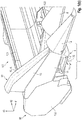
- FIG. 1A and B Shown in Fig. 1A and B in a perspective view is a respective cutout from a partially assembled attachment 100 for harvesting crop rows (not depicted) with an outer stalk divider 1.
- Such an attachment 100 is mounted to a self-driving agricultural machine (not depicted), for example a combine harvester, a forage harvester or a tractor, for harvesting the crop.
- the attachment 100 is here a corn picker type.
- the terms attachment 100 and corn picker are therefore used synonymously below.
- the attachment 100 exhibits a frame that encompasses two lateral walls 102 spaced apart from each other, which are joined together by means of a rear wall 101 and/or at least one cross beam 103.
- the rear wall 101 and/or cross beam 103 extend in a direction of extension 42 transverse to a traveling direction 41, in which the attachment 100 is moved during a harvesting operation.
- the two lateral walls 102 are each located at the outer ends 99 of the attachment 100 as viewed in the direction of extension 42.
- a respective outer stalk divider 1 is here arranged on both lateral walls 102 and roughly flush with the rear wall 101.
- the outer stalk dividers 1 in one embodiment are not displaceable in and opposite the direction of extension 42.
- the attachments 100 may have outer stalk dividers 1 that can be displaced in and opposite the direction of extension 42.
- the inner stalk dividers 8 here provided may be displaced in and opposite the direction of extension 42, in particular along the cross beam 103, so that the attachment 100 can be adjusted to different distances between the crop rows.
- the attachments 100 may have inner stalk dividers 8 that cannot be displaced in and opposite the direction of extension 42.
- the outer stalk dividers 1 of the attachment 100 each exhibit a base body 11, which extends in the traveling direction 41, and a hood 12.
- the hood 12 is situated on the base body 11 at the front in the traveling direction 41. It tapers in the traveling direction 41.
- the hood 12 may, for maintenance purposes, be folded or rotated in and against a radial folding direction 72 around a folding axis 7 extending in an axial folding direction 71 parallel to the direction of extension 42.
- the outer stalk divider 1 also includes a cover element 10.
- the cover element 10 In the traveling direction 41, the cover element 10 is located behind the hood 12 and on an upper side 33 of the outer stalk divider 1.
- the upper side 33 of the base body 11 exhibits a surface 15 extending in the traveling direction 41 (see Fig. 2A , 3A ).
- the cover element 10 can be reversibly vertically adjusted, through translation and/or rotation, from a base position G into a lifted position A in a vertical direction 43 extending transverse to the traveling direction 41 and transverse to the direction of extension 42. This makes it possible to adjust the outer stalk divider 1 to crops with higher lying fruit.
- Fig. 1A shows the cover element 10 in the base position G, in which it extends at least partially along the surface 15 of the base body 11.
- the cover element 10 abuts against the base body 11 in the base position G.
- the surface 15 of the base body 11 runs at least partially against the traveling direction 41, rising in the vertical direction 43. This enables a gentle lifting of the crop stems during the harvesting operation.
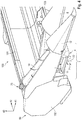
- Fig. 1B shows the cover element 10 in the lifted position A, in which it is swiveled, or pivoted, in a radial swiveling direction 22 around a swiveling axis 2 (see Fig. 3B ) extending in an axial swiveling direction 21 parallel to the direction of extension 42.
- a loss preventer 13 is arranged on the cover element 10, and closes a gap 3 (see Fig. 2B ) between the cover element 10 and base body 11, so as to avoid losses in fruit owing to fruit that falls through the gap 3 during the harvesting operation.
- Fig. 2A shows another perspective view of another embodiment of an attachment 100 with an outer stalk divider 1 with a cover element 10 in the lifted position A.
- a loss preventer 13 which closes the gap 3 between the cover element 10 and base body 11.
- the loss preventer 13 is here made out of a flexible web, for example a canvas, which may be made of cloth, film or rubber like materials. Therefore, the terms loss preventer 13 and canvas are used synonymously within the framework of Fig. 2 .
- the surface 15 of the base body 11 and an inner surface 19 facing it (see Figs. 2B and 3B ) of the cover element 10 together border an interior space 16.
- the loss preventer 13 automatically folds, so that it is situated in the interior space 16 in the base position G of the cover element 10.
- the cover element 10 in this embodiment is fixed in the lifted position A by means of a manually actuatable lever 63 as shown in Fig. 2A .
- the lever 63 exhibits a handhold in the form of a handle 64, making it easy to actuate.
- the base body 11 has arranged on it a first fastening component 27, on which the lever 63 is fastened so that it can turn around a rotational axis 6 extending in an axial rotational direction 61 parallel to the direction of extension 62, in and opposite a radial rotational direction 62.
- the lever In the base position G, the lever is situated in the interior space 16. The lever 63 then abuts against the surface 15 of the base body 11. In order to fix the cover element 10 in the lifted position A, the lever 63 is turned or pivoted in the radial rotational direction 62 around the rotational axis 6. The cover element 10 has arranged on it a second fastening component 28, on which the lever 63 may be latched.
- the cover element 10 may be automatically lifted, in particular by means of a hydraulic, pneumatic or electrical actuator.
- the cover element 10 may be latched in the lifted position, or may be preferably held in the lifted position by a holding force, by a biasing device, for example a spring, whether mechanical (compression or tension) or pneumatic (e.g., gas pressure spring).
- a biasing device for example a spring, whether mechanical (compression or tension) or pneumatic (e.g., gas pressure spring).
- the cover element 10 is automatically deflected downwardly given an excessive load, e.g., owing to resting crop.
- Another advantage to being held by a restoring force exerted in by the spring is that the cover element 10 is automatically repositioned when an overload is no longer present.
- Fig. 2B schematically depicts another perspective view of a respective cutout from the base body 11 and from the lifted cover element 10 of the outer stalk divider 1.
- the loss preventer 13 and fastening components 27, 28 are not shown. This reveals the gap 3 between the cover element 10 in the lifted position A and the base body 11.
- cover element 10 and base body 11 are fastening webs, on which the loss preventer 13 can be fastened. Lateral walls 25 are here used for the fastening webs 31 on both the base body 11 and the cover element 10.
- Fig. 2C shows a magnified cutout of the outer stalk divider on Fig. 2A , wherein the cover element 10 is located in the base position.
- the first and second fastening components 27, 28 here each exhibit a tab (not marked), which are joined together by means of a fastening screw 29.
- the upper side 33 of the cover element 10 exhibits an outer surface 17.
- the outer surface 17 is situated so as to face away from the surface 15 of the base body 11. It is at least partially arched in design.
- the outer surface 17 of the cover element 10 is here roughly U-shaped (inverted) in design. For this reason, the outer surface exhibits two opposing lateral surfaces 34 and a connecting surface 32 that joins the latter together. The respective transitions 18 between the lateral surfaces 34 and connecting surface 32 are here arched, in particular circular, in design. As a result, the cover element 10 exhibits no edges that might cause the stalks to kink. The stalks then slide along the outer surface 17. This enables a gentle untangling and/or lifting of the stalks of the crop hanging over the outer stalk divider 1 during the harvesting operation, and fewer bulky components are lost on the outer stalk dividers 1.
- the cover element 10 exhibits a width 52 in the direction of extension 42 that is roughly equal to a width 51 of the surface 15 of the base body 11. This also prevents the stalks from kinking. In addition, less dirt and crop can thereby penetrate into the base body 11, in particular into the interior space 16.
- Fig. 3A shows a cutout from the outer stalk divider 1 on Fig. 2A without the cover element 10.
- This reveals a hinge part 35 to which the cover element 10 can be mounted.
- the hinge part 35 is situated so that it can turn around bolts 20 ( Fig. 3B ), which extend in the axial swiveling direction 21 around the swiveling (pivot) axis 2.
- bolts 20 Fig. 3B
- the cover element 10 When the cover element 10 is arranged on the hinge part 35, it can thus be swiveled or pivoted from the base position G in the radial swiveling direction 22 around the swiveling axis 22 into the lifted position A and back again.
- Fig. 3B also shows a cutout of the base body 11 of the outer stalk divider 1 on Fig. 2A .
- the hinge part 35 has here been removed.
- the bolts 20 are detachably secured to each other by means of a sleeve 23.
- the cover element 10 can be detached from the base body 11, such that it is removeably coupled to the base body.
- a stalk lifting auger 14 When the cover element 10 is removed, a stalk lifting auger 14 can be situated on the base body 11. For this reason, a receptacle 26, in particular a gear arrangement, is provided below the bolts 20 for the stalk lifting auger 14, into which the latter can be inserted or to which the latter can be operably connected.
- the receptacle 26 is arranged in a front wall 24 of the base body 11.
- Fig. 4 shows a perspective view of a cutout from a partially assembled attachment 100 on Fig. 1 with the outer stalk divider 1.
- the stalk lifting auger 14 is located on the base body 11 in place of the cover element 10.
- Fig. 5 schematically depicts another embodiment of an outer stalk divider 1.
- the stalk lifting auger 14 is situated below the cover element 10.
- the cover element 10 does not completely cover the stalk lifting auger 14.
- the stalk lifting auger 14 is completely incorporated in the interior space 16 in the base position G.
- the cover element 10 can be detached from the outer stalk divider 1.
- a plate 13 which together therewith can be moved from the base position G into the lifted position A.
- the terms plate and loss preventer 13 are thus used synonymously.
- the plate 13 In the base position G shown here, the plate 13 is situated to the side of the base body 11. In one embodiment the plate may be arranged in a gap-shaped receptacle (not shown) of the base body 11 in the base position G.
- the cover element 10 may be easily and quickly moved by the user from the base position G into the lifted position, in particular without additional tools, which positioning reduces fruit losses during the harvest.
- the cover element may be quickly dismantled, so as to be replaced by a stalk lifting auger 14. Further, the device is easy to clean.
Landscapes
- Life Sciences & Earth Sciences (AREA)
- Environmental Sciences (AREA)
- Outside Dividers And Delivering Mechanisms For Harvesters (AREA)
- Harvesting Machines For Specific Crops (AREA)
Claims (13)
- Un diviseur de tiges extérieur (1) pour un accessoire pour récolter une culture en rangs, le diviseur de tiges extérieur (1) comprenant : un corps de base (11) qui s'étend dans une direction de marche (41) et comprend une surface (17) qui s'étend dans la direction de marche (41) sur un côté supérieur (33) et un capot (12) qui est situé à l'avant du corps de base (11) par rapport à la direction de marche (41) et qui est effilé dans la direction de marche (41), le diviseur de tiges extérieur (1) comprenant un élément de recouvrement (10) qui, dans la direction de marche (41), est situé derrière le capot (12) et sur le côté supérieur (33), l'élément de recouvrement (10) s'étendant au moins partiellement le long de la surface (15) du corps de base (11) et comprenant au moins une surface extérieure partiellement arquée (17) orientée à l'opposé de la surface (15) du corps de base (11), l'élément de recouvrement (10) étant réglable en hauteur de façon réversible dans une direction verticale (43) depuis une position de base (G) vers une position relevée (A), caractérisé en ce que l'élément de liaison (10) comprend un moyen anti-perte fermant au moins une portion d'un intervalle (3) formé entre le corps de base (11) et l'élément de recouvrement (10) à l'état soulevé (A).
- Le diviseur de tiges extérieur (1) selon la revendication 1, dans lequel une section transversale de la surface extérieure (17) est de conformation ronde, ovale ou en U.
- Le diviseur de tiges extérieur (1) selon l'une des revendications précédentes, dans lequel, dans une direction d'extension (42) qui s'étend transversalement à la direction de marche (41), l'élément de recouvrement (10) présente une largeur (52) qui est égale ou supérieure à une largeur (51) de la surface (15) du corps de base (11) .
- Le diviseur de tiges extérieur (1) selon l'une des revendications précédentes, dans lequel la surface (15) du corps de base (11) s'élève dans la direction verticale (43) au moins partiellement à l'opposé de la direction de marche (41), et l'élément de recouvrement (10) suit le profil du corps de base (11).
- Le diviseur de tiges extérieur (1) selon l'une des revendications précédentes, dans lequel l'élément de recouvrement (10) est pivotant autour d'un axe de pivot (2) s'étendant parallèlement à la direction d'extension (42).
- Le diviseur de tiges extérieur (1) selon l'une des revendications précédentes, comprenant en outre un dispositif de verrou immobilisant l'élément de recouvrement (10) dans la position relevée (A) et/ou dans la position de base (G).
- Le diviseur de tiges extérieur (1) selon l'une des revendications précédentes, comprenant en outre un dispositif de contrainte maintenant l'élément de recouvrement dans la position relevée (A).
- Le diviseur de tiges extérieur (1) selon l'une des revendications précédentes, dans lequel une surface intérieure de l'élément de recouvrement (19) et la surface (15) du corps de base (11) définissent un espace intérieur (16).
- Le diviseur de tiges extérieur (1) selon l'une des revendications précédentes, dans lequel le moyen anti-perte comprend un lé flexible, le lé flexible étant plié dans l'espace intérieur lorsque l'élément de recouvrement (10) est dans la position de base (G).
- Le diviseur de tiges extérieur (1) selon l'une des revendications précédentes, dans lequel l'élément de recouvrement (10) est détachable de façon réversible du corps de base (11).
- Le diviseur de tiges extérieur (1) selon la revendication 8, comprenant en outre une vis lève-tiges (14) disposée dans l'espace intérieur.
- Un accessoire pour récolter des rangs de culture comprenant deux diviseurs de tiges extérieurs (1) selon l'une des revendications précédentes, dans lequel les diviseurs de tiges extérieurs (1) sont disposés aux extrémités extérieures de l'accessoire vu dans une direction d'extension (42) .
- L'accessoire selon la revendication 12, dans lequel les diviseurs de tiges extérieurs (1) sont situés sur l'accessoire, de sorte qu'ils ne peuvent pas être déplacés dans la direction d'extension (42) ni à l'opposé de celle-ci.
Applications Claiming Priority (1)
| Application Number | Priority Date | Filing Date | Title |
|---|---|---|---|
| US15/671,745 US10462969B2 (en) | 2017-08-08 | 2017-08-08 | Attachment for harvesting row crops |
Publications (2)
| Publication Number | Publication Date |
|---|---|
| EP3440920A1 EP3440920A1 (fr) | 2019-02-13 |
| EP3440920B1 true EP3440920B1 (fr) | 2021-08-25 |
Family
ID=62063362
Family Applications (1)
| Application Number | Title | Priority Date | Filing Date |
|---|---|---|---|
| EP18169147.8A Active EP3440920B1 (fr) | 2017-08-08 | 2018-04-25 | Diviseur extérieur d'épis |
Country Status (3)
| Country | Link |
|---|---|
| US (1) | US10462969B2 (fr) |
| EP (1) | EP3440920B1 (fr) |
| HU (1) | HUE056056T2 (fr) |
Families Citing this family (10)
| Publication number | Priority date | Publication date | Assignee | Title |
|---|---|---|---|---|
| US20230117424A1 (en) * | 2018-08-24 | 2023-04-20 | Fox Max LLC | Agricultural tools for assisting in the harvesting of crops |
| US10897846B2 (en) * | 2018-10-31 | 2021-01-26 | Deere & Company | Corn harvester |
| US11032969B2 (en) * | 2019-04-11 | 2021-06-15 | Cnh Industrial America Llc | Crop divider for a corn header |
| US12096718B2 (en) * | 2021-05-27 | 2024-09-24 | Deere & Company | Controllable end dividers |
| US20230270049A1 (en) * | 2022-02-28 | 2023-08-31 | Deere & Company | Controllable end dividers |
| WO2023212329A1 (fr) * | 2022-04-29 | 2023-11-02 | Cnh Industrial America Llc | Diviseur de récolte actif pour organe de coupe |
| JP7789625B2 (ja) * | 2022-06-13 | 2025-12-22 | ヤンマーホールディングス株式会社 | 収穫機 |
| WO2024097405A1 (fr) * | 2022-11-03 | 2024-05-10 | Cnh Industrial America Llc | Tablier de coupe agricole avec diviseur de maïs géant actionné à distance |
| USD1120036S1 (en) * | 2023-04-26 | 2026-03-24 | Claas Kgaa Mbh | Corn picker |
| USD1115868S1 (en) * | 2023-06-22 | 2026-03-03 | Deere & Company | Divider |
Family Cites Families (12)
| Publication number | Priority date | Publication date | Assignee | Title |
|---|---|---|---|---|
| DE3048327A1 (de) * | 1980-12-20 | 1982-07-29 | Claas Ohg, 4834 Harsewinkel | Erntevorsatz fuer in reihen stehendes erntegut |
| DE3213542A1 (de) * | 1982-04-10 | 1983-10-20 | Klemens 4730 Ahlen Kalverkamp | Verfahren und geraet zum ernten von mais oder anderen koernerfruechten |
| US4493181A (en) * | 1984-05-14 | 1985-01-15 | Farmer's Factory Co. | Attachment for the snouts of combines and the like |
| US5195309A (en) | 1991-08-28 | 1993-03-23 | Deere & Company | Plastic crop dividers for a row crop header |
| US5444968A (en) * | 1994-11-09 | 1995-08-29 | Barton; Herald M. | Outboard crop divider structure guard assembly |
| US5775076A (en) | 1996-05-10 | 1998-07-07 | Deere & Company | Fender extension for a corn harvester |
| US5865019A (en) * | 1996-12-17 | 1999-02-02 | New Holland North America, Inc. | Plastic divider assembly with frame for a corn head |
| US6625969B2 (en) * | 2001-08-27 | 2003-09-30 | Plastic Designs, Inc. | Tip for covering the snoot of a crop divider |
| DE10317469B4 (de) | 2003-04-16 | 2019-03-07 | Maschinenfabrik Kemper Gmbh & Co. Kg | Erntevorsatz mit einer Stängelheberschnecke |
| US6901730B1 (en) | 2003-12-16 | 2005-06-07 | Cnh America Llc | End hood extension for a corn header |
| AR076568A1 (es) | 2010-05-11 | 2011-06-22 | Allochis Jose Luis | Cabezal maicero con puntones y capot laterales articulados. |
| WO2014085811A1 (fr) | 2012-11-30 | 2014-06-05 | Marion Calmer | Unité de tête de rangée étroite |
-
2017
- 2017-08-08 US US15/671,745 patent/US10462969B2/en active Active
-
2018
- 2018-04-25 HU HUE18169147A patent/HUE056056T2/hu unknown
- 2018-04-25 EP EP18169147.8A patent/EP3440920B1/fr active Active
Also Published As
| Publication number | Publication date |
|---|---|
| US10462969B2 (en) | 2019-11-05 |
| EP3440920A1 (fr) | 2019-02-13 |
| US20190045710A1 (en) | 2019-02-14 |
| HUE056056T2 (hu) | 2022-01-28 |
Similar Documents
| Publication | Publication Date | Title |
|---|---|---|
| EP3440920B1 (fr) | Diviseur extérieur d'épis | |
| US9668413B2 (en) | Deck plate control system for a header of an agricultural harvester | |
| EP3308624B1 (fr) | Roues de jauge de compartiment d'alimentation combiné | |
| EP3258771B1 (fr) | Dispositif de réglage de diviseur et couvercle pour moissonneuse agricole | |
| EP3090620B1 (fr) | Fixation de couvercle latéral de tête de récolte pour une moissonneuse agricole | |
| US20150250098A1 (en) | Stalk Breaker for a Corn Head | |
| EP4044791B1 (fr) | Tête de coupe à plusieurs segments | |
| EP3657932B1 (fr) | Ensemble courroie de transport pour une moissonneuse agricole | |
| BR102019008401A2 (pt) | Espigadeira de cultivo em fileira e divisor de cultivo para uma máquina agrícola, e, combinada | |
| US12010950B2 (en) | Cam track adjustment assembly for a harvesting reel | |
| US4433531A (en) | Forage harvester corn snapping header | |
| KR200443646Y1 (ko) | 예취기용 가이드 | |
| US2835095A (en) | Spring-loaded bail for stripper type cotton harvesters | |
| US1882875A (en) | Grain divider extension | |
| US8769916B2 (en) | Farm implement for harvesting and mowing that is relesably couplable to and powered by a tractor | |
| KR200462539Y1 (ko) | 예취기용 가이드장치 | |
| CN215601998U (zh) | 一种青贮机折叠割台导引杆组件以及青贮机折叠割台 | |
| JP6265880B2 (ja) | 普通型コンバイン | |
| JP2522463Y2 (ja) | 複数条刈り用バインダー | |
| DE102016103980B4 (de) | Landwirtschaftliches Vorsatzgerät und landwirtschaftliches Erntefahrzeug | |
| JPH081628Y2 (ja) | コンバインの分草構造 | |
| US701301A (en) | Harvester attachment. | |
| DE102006051618A1 (de) | Reihensensoranordnung | |
| JPH0817630B2 (ja) | 全稈投入型脱穀装置を有するコンバインの刈取部自動停止装置 | |
| JP2013165667A (ja) | とうもろこし収穫機の収穫前処理装置 |
Legal Events
| Date | Code | Title | Description |
|---|---|---|---|
| PUAI | Public reference made under article 153(3) epc to a published international application that has entered the european phase |
Free format text: ORIGINAL CODE: 0009012 |
|
| STAA | Information on the status of an ep patent application or granted ep patent |
Free format text: STATUS: THE APPLICATION HAS BEEN PUBLISHED |
|
| AK | Designated contracting states |
Kind code of ref document: A1 Designated state(s): AL AT BE BG CH CY CZ DE DK EE ES FI FR GB GR HR HU IE IS IT LI LT LU LV MC MK MT NL NO PL PT RO RS SE SI SK SM TR |
|
| AX | Request for extension of the european patent |
Extension state: BA ME |
|
| STAA | Information on the status of an ep patent application or granted ep patent |
Free format text: STATUS: REQUEST FOR EXAMINATION WAS MADE |
|
| 17P | Request for examination filed |
Effective date: 20190813 |
|
| RBV | Designated contracting states (corrected) |
Designated state(s): AL AT BE BG CH CY CZ DE DK EE ES FI FR GB GR HR HU IE IS IT LI LT LU LV MC MK MT NL NO PL PT RO RS SE SI SK SM TR |
|
| GRAP | Despatch of communication of intention to grant a patent |
Free format text: ORIGINAL CODE: EPIDOSNIGR1 |
|
| STAA | Information on the status of an ep patent application or granted ep patent |
Free format text: STATUS: GRANT OF PATENT IS INTENDED |
|
| INTG | Intention to grant announced |
Effective date: 20210531 |
|
| GRAS | Grant fee paid |
Free format text: ORIGINAL CODE: EPIDOSNIGR3 |
|
| GRAA | (expected) grant |
Free format text: ORIGINAL CODE: 0009210 |
|
| STAA | Information on the status of an ep patent application or granted ep patent |
Free format text: STATUS: THE PATENT HAS BEEN GRANTED |
|
| AK | Designated contracting states |
Kind code of ref document: B1 Designated state(s): AL AT BE BG CH CY CZ DE DK EE ES FI FR GB GR HR HU IE IS IT LI LT LU LV MC MK MT NL NO PL PT RO RS SE SI SK SM TR |
|
| REG | Reference to a national code |
Ref country code: CH Ref legal event code: EP |
|
| REG | Reference to a national code |
Ref country code: IE Ref legal event code: FG4D Ref country code: AT Ref legal event code: REF Ref document number: 1422835 Country of ref document: AT Kind code of ref document: T Effective date: 20210915 |
|
| REG | Reference to a national code |
Ref country code: DE Ref legal event code: R096 Ref document number: 602018022253 Country of ref document: DE |
|
| REG | Reference to a national code |
Ref country code: LT Ref legal event code: MG9D |
|
| REG | Reference to a national code |
Ref country code: NL Ref legal event code: MP Effective date: 20210825 |
|
| REG | Reference to a national code |
Ref country code: AT Ref legal event code: MK05 Ref document number: 1422835 Country of ref document: AT Kind code of ref document: T Effective date: 20210825 |
|
| REG | Reference to a national code |
Ref country code: HU Ref legal event code: AG4A Ref document number: E056056 Country of ref document: HU |
|
| PG25 | Lapsed in a contracting state [announced via postgrant information from national office to epo] |
Ref country code: RS Free format text: LAPSE BECAUSE OF FAILURE TO SUBMIT A TRANSLATION OF THE DESCRIPTION OR TO PAY THE FEE WITHIN THE PRESCRIBED TIME-LIMIT Effective date: 20210825 Ref country code: SE Free format text: LAPSE BECAUSE OF FAILURE TO SUBMIT A TRANSLATION OF THE DESCRIPTION OR TO PAY THE FEE WITHIN THE PRESCRIBED TIME-LIMIT Effective date: 20210825 Ref country code: HR Free format text: LAPSE BECAUSE OF FAILURE TO SUBMIT A TRANSLATION OF THE DESCRIPTION OR TO PAY THE FEE WITHIN THE PRESCRIBED TIME-LIMIT Effective date: 20210825 Ref country code: FI Free format text: LAPSE BECAUSE OF FAILURE TO SUBMIT A TRANSLATION OF THE DESCRIPTION OR TO PAY THE FEE WITHIN THE PRESCRIBED TIME-LIMIT Effective date: 20210825 Ref country code: ES Free format text: LAPSE BECAUSE OF FAILURE TO SUBMIT A TRANSLATION OF THE DESCRIPTION OR TO PAY THE FEE WITHIN THE PRESCRIBED TIME-LIMIT Effective date: 20210825 Ref country code: PT Free format text: LAPSE BECAUSE OF FAILURE TO SUBMIT A TRANSLATION OF THE DESCRIPTION OR TO PAY THE FEE WITHIN THE PRESCRIBED TIME-LIMIT Effective date: 20211227 Ref country code: NO Free format text: LAPSE BECAUSE OF FAILURE TO SUBMIT A TRANSLATION OF THE DESCRIPTION OR TO PAY THE FEE WITHIN THE PRESCRIBED TIME-LIMIT Effective date: 20211125 Ref country code: AT Free format text: LAPSE BECAUSE OF FAILURE TO SUBMIT A TRANSLATION OF THE DESCRIPTION OR TO PAY THE FEE WITHIN THE PRESCRIBED TIME-LIMIT Effective date: 20210825 Ref country code: BG Free format text: LAPSE BECAUSE OF FAILURE TO SUBMIT A TRANSLATION OF THE DESCRIPTION OR TO PAY THE FEE WITHIN THE PRESCRIBED TIME-LIMIT Effective date: 20211125 Ref country code: LT Free format text: LAPSE BECAUSE OF FAILURE TO SUBMIT A TRANSLATION OF THE DESCRIPTION OR TO PAY THE FEE WITHIN THE PRESCRIBED TIME-LIMIT Effective date: 20210825 |
|
| PG25 | Lapsed in a contracting state [announced via postgrant information from national office to epo] |
Ref country code: PL Free format text: LAPSE BECAUSE OF FAILURE TO SUBMIT A TRANSLATION OF THE DESCRIPTION OR TO PAY THE FEE WITHIN THE PRESCRIBED TIME-LIMIT Effective date: 20210825 Ref country code: LV Free format text: LAPSE BECAUSE OF FAILURE TO SUBMIT A TRANSLATION OF THE DESCRIPTION OR TO PAY THE FEE WITHIN THE PRESCRIBED TIME-LIMIT Effective date: 20210825 Ref country code: GR Free format text: LAPSE BECAUSE OF FAILURE TO SUBMIT A TRANSLATION OF THE DESCRIPTION OR TO PAY THE FEE WITHIN THE PRESCRIBED TIME-LIMIT Effective date: 20211126 |
|
| PG25 | Lapsed in a contracting state [announced via postgrant information from national office to epo] |
Ref country code: NL Free format text: LAPSE BECAUSE OF FAILURE TO SUBMIT A TRANSLATION OF THE DESCRIPTION OR TO PAY THE FEE WITHIN THE PRESCRIBED TIME-LIMIT Effective date: 20210825 |
|
| PG25 | Lapsed in a contracting state [announced via postgrant information from national office to epo] |
Ref country code: DK Free format text: LAPSE BECAUSE OF FAILURE TO SUBMIT A TRANSLATION OF THE DESCRIPTION OR TO PAY THE FEE WITHIN THE PRESCRIBED TIME-LIMIT Effective date: 20210825 |
|
| REG | Reference to a national code |
Ref country code: DE Ref legal event code: R097 Ref document number: 602018022253 Country of ref document: DE |
|
| PG25 | Lapsed in a contracting state [announced via postgrant information from national office to epo] |
Ref country code: SM Free format text: LAPSE BECAUSE OF FAILURE TO SUBMIT A TRANSLATION OF THE DESCRIPTION OR TO PAY THE FEE WITHIN THE PRESCRIBED TIME-LIMIT Effective date: 20210825 Ref country code: SK Free format text: LAPSE BECAUSE OF FAILURE TO SUBMIT A TRANSLATION OF THE DESCRIPTION OR TO PAY THE FEE WITHIN THE PRESCRIBED TIME-LIMIT Effective date: 20210825 Ref country code: RO Free format text: LAPSE BECAUSE OF FAILURE TO SUBMIT A TRANSLATION OF THE DESCRIPTION OR TO PAY THE FEE WITHIN THE PRESCRIBED TIME-LIMIT Effective date: 20210825 Ref country code: EE Free format text: LAPSE BECAUSE OF FAILURE TO SUBMIT A TRANSLATION OF THE DESCRIPTION OR TO PAY THE FEE WITHIN THE PRESCRIBED TIME-LIMIT Effective date: 20210825 Ref country code: CZ Free format text: LAPSE BECAUSE OF FAILURE TO SUBMIT A TRANSLATION OF THE DESCRIPTION OR TO PAY THE FEE WITHIN THE PRESCRIBED TIME-LIMIT Effective date: 20210825 Ref country code: AL Free format text: LAPSE BECAUSE OF FAILURE TO SUBMIT A TRANSLATION OF THE DESCRIPTION OR TO PAY THE FEE WITHIN THE PRESCRIBED TIME-LIMIT Effective date: 20210825 |
|
| PLBE | No opposition filed within time limit |
Free format text: ORIGINAL CODE: 0009261 |
|
| STAA | Information on the status of an ep patent application or granted ep patent |
Free format text: STATUS: NO OPPOSITION FILED WITHIN TIME LIMIT |
|
| PG25 | Lapsed in a contracting state [announced via postgrant information from national office to epo] |
Ref country code: IT Free format text: LAPSE BECAUSE OF FAILURE TO SUBMIT A TRANSLATION OF THE DESCRIPTION OR TO PAY THE FEE WITHIN THE PRESCRIBED TIME-LIMIT Effective date: 20210825 |
|
| 26N | No opposition filed |
Effective date: 20220527 |
|
| PG25 | Lapsed in a contracting state [announced via postgrant information from national office to epo] |
Ref country code: SI Free format text: LAPSE BECAUSE OF FAILURE TO SUBMIT A TRANSLATION OF THE DESCRIPTION OR TO PAY THE FEE WITHIN THE PRESCRIBED TIME-LIMIT Effective date: 20210825 |
|
| REG | Reference to a national code |
Ref country code: CH Ref legal event code: PL |
|
| GBPC | Gb: european patent ceased through non-payment of renewal fee |
Effective date: 20220425 |
|
| PG25 | Lapsed in a contracting state [announced via postgrant information from national office to epo] |
Ref country code: MC Free format text: LAPSE BECAUSE OF FAILURE TO SUBMIT A TRANSLATION OF THE DESCRIPTION OR TO PAY THE FEE WITHIN THE PRESCRIBED TIME-LIMIT Effective date: 20210825 Ref country code: LU Free format text: LAPSE BECAUSE OF NON-PAYMENT OF DUE FEES Effective date: 20220425 Ref country code: LI Free format text: LAPSE BECAUSE OF NON-PAYMENT OF DUE FEES Effective date: 20220430 Ref country code: GB Free format text: LAPSE BECAUSE OF NON-PAYMENT OF DUE FEES Effective date: 20220425 Ref country code: FR Free format text: LAPSE BECAUSE OF NON-PAYMENT OF DUE FEES Effective date: 20220430 Ref country code: CH Free format text: LAPSE BECAUSE OF NON-PAYMENT OF DUE FEES Effective date: 20220430 |
|
| PG25 | Lapsed in a contracting state [announced via postgrant information from national office to epo] |
Ref country code: IE Free format text: LAPSE BECAUSE OF NON-PAYMENT OF DUE FEES Effective date: 20220425 |
|
| P01 | Opt-out of the competence of the unified patent court (upc) registered |
Effective date: 20230516 |
|
| PG25 | Lapsed in a contracting state [announced via postgrant information from national office to epo] |
Ref country code: MK Free format text: LAPSE BECAUSE OF FAILURE TO SUBMIT A TRANSLATION OF THE DESCRIPTION OR TO PAY THE FEE WITHIN THE PRESCRIBED TIME-LIMIT Effective date: 20210825 Ref country code: CY Free format text: LAPSE BECAUSE OF FAILURE TO SUBMIT A TRANSLATION OF THE DESCRIPTION OR TO PAY THE FEE WITHIN THE PRESCRIBED TIME-LIMIT Effective date: 20210825 |
|
| PG25 | Lapsed in a contracting state [announced via postgrant information from national office to epo] |
Ref country code: MT Free format text: LAPSE BECAUSE OF FAILURE TO SUBMIT A TRANSLATION OF THE DESCRIPTION OR TO PAY THE FEE WITHIN THE PRESCRIBED TIME-LIMIT Effective date: 20210825 |
|
| PGFP | Annual fee paid to national office [announced via postgrant information from national office to epo] |
Ref country code: DE Payment date: 20250422 Year of fee payment: 8 |
|
| PGFP | Annual fee paid to national office [announced via postgrant information from national office to epo] |
Ref country code: HU Payment date: 20250424 Year of fee payment: 8 |
|
| PGFP | Annual fee paid to national office [announced via postgrant information from national office to epo] |
Ref country code: BE Payment date: 20250418 Year of fee payment: 8 |
|
| PG25 | Lapsed in a contracting state [announced via postgrant information from national office to epo] |
Ref country code: TR Free format text: LAPSE BECAUSE OF FAILURE TO SUBMIT A TRANSLATION OF THE DESCRIPTION OR TO PAY THE FEE WITHIN THE PRESCRIBED TIME-LIMIT Effective date: 20210825 |