EP3440932B1 - Réglage active des vibrations - Google Patents
Réglage active des vibrations Download PDFInfo
- Publication number
- EP3440932B1 EP3440932B1 EP18187795.2A EP18187795A EP3440932B1 EP 3440932 B1 EP3440932 B1 EP 3440932B1 EP 18187795 A EP18187795 A EP 18187795A EP 3440932 B1 EP3440932 B1 EP 3440932B1
- Authority
- EP
- European Patent Office
- Prior art keywords
- damping
- utility vehicle
- distributor linkage
- vertical axis
- driving state
- Prior art date
- Legal status (The legal status is an assumption and is not a legal conclusion. Google has not performed a legal analysis and makes no representation as to the accuracy of the status listed.)
- Active
Links
Images


Classifications
-
- A—HUMAN NECESSITIES
- A01—AGRICULTURE; FORESTRY; ANIMAL HUSBANDRY; HUNTING; TRAPPING; FISHING
- A01M—CATCHING, TRAPPING OR SCARING OF ANIMALS; APPARATUS FOR THE DESTRUCTION OF NOXIOUS ANIMALS OR NOXIOUS PLANTS
- A01M7/00—Special adaptations or arrangements of liquid-spraying apparatus for purposes covered by this subclass
- A01M7/005—Special arrangements or adaptations of the spraying or distributing parts, e.g. adaptations or mounting of the spray booms, mounting of the nozzles, protection shields
- A01M7/0053—Mounting of the spraybooms
- A01M7/0057—Mounting of the spraybooms with active regulation of the boom position
Definitions
- the invention relates to a control and / or regulating system for an agricultural utility vehicle according to the preamble of claim 1. Furthermore, the invention relates to an agricultural utility vehicle and a method for controlling and / or regulating an agricultural utility vehicle.
- Such systems are used for agricultural utility vehicles for the application of material such as fertilizers, pesticides or seeds.
- the agricultural utility vehicles In order to spread the material over a large area and efficiently on the field to be worked, the agricultural utility vehicles have a distributor rod with several spray nozzles.
- the distributor boom extends across the direction of travel and can have working widths of up to 40 m.
- the spray nozzles which are attached at regular intervals on the distributor rod, are used to apply the material to the soil to be worked.
- the distribution linkage can swing open when the utility vehicle is in operation, for example when braking or accelerating.
- the accompanying uncontrolled movement of the distributor rod not only causes an inhomogeneous distribution of the material to be spread on the field soil.
- the distributor rod can also be overloaded, which in extreme cases can be irreparably damaged.
- Yaw vibrations around a vertical axis or horizontal vibrations are to be regarded as critical.
- Horizontal vibrations mainly describe vibrations in the direction of travel or vibrations around an axis perpendicular to the soil to be worked. They cause the distributor boom to move over the field soil at different speeds to the side.
- the distributor linkage fluctuates back and forth between reversal points, so that overdosing or underdosing can occur between the reversal points.
- the horizontal yaw oscillation leads to an undesirable inhomogeneous coverage of the soil and / or vegetation to be worked.
- the distribution linkage has a middle part, for example a centrally arranged frame, and two side arms connected to the middle part with several linkage sections which are connected by joints and which can be folded in to one another in the transport position and unfolded in the working position.
- Servomotors and / or adjustable damper systems with variable damping properties are provided, which are assigned to the distributor linkage.
- a control and regulating device is provided which, based on measurement signals from sensors, supplies control signals or setting parameters for the servomotors and damping systems.
- the damping is adjusted as a reaction to the vibratory movements of the distributor rod. It reacts to the vibrations that occur with active damping by means of electrorheological dampers. In general, it is particularly advantageous that vibrations that occur are damped as quickly as possible so that the distributor rod can be prevented from swinging up at an early stage. In some driving situations, such as when cornering, for example, it may be necessary to continuously increase the damping, depending on the radius of curvature of the curve to be driven, since the distributor linkage can be accelerated very strongly when cornering. This in turn causes high mechanical loads at the coupling points between the agricultural utility vehicle and the distributor linkage. In the known damping system, however, it is only possible to react to the vibration that occurs and not to the triggering state of the vibration, such as cornering, for example.
- the invention is therefore based on the object of improving a control and / or regulating system of the type mentioned at the outset in such a way that damping of yaw vibrations around the vertical axis of the Distribution linkage can be improved depending on the situation.
- the invention is also based on the object of specifying an agricultural utility vehicle and a method for controlling and / or regulating an agricultural utility vehicle.
- this object is achieved by a control and / or regulating system having the features of claim 1.
- the object is achieved by the subject matter of claim 10.
- the object with regard to the method is achieved by the subject matter of claim 11.
- the invention is based on the idea of specifying a control and / or regulating system for an agricultural utility vehicle, which comprises a distributor linkage for spreading material such as fertilizers, pesticides or seeds, which extends transversely to the direction of travel and a central part and two with the central part has side arms connected by joints with a plurality of rod sections connected by joints, which can be folded in to one another in the transport position and folded out in the working position.
- At least one adjusting device is assigned to the distributor linkage, as a result of which the distributor linkage is arranged to be pivotable about a vertical axis.
- At least one sensor is assigned to the utility vehicle.
- the system has a data processing unit which is configured in such a way that the signals from the sensor are processed and on the basis of which an actuating signal for the actuating device is generated.
- the data processing unit is configured in such a way that, depending on the different driving conditions of the agricultural utility vehicle, different damping of yaw vibrations occurring on the distributor linkage can be set around the vertical axis.
- the setting of a different damping takes place via the setting of a different control parameter depending on the driving state.
- the required gain for damping yaw vibrations is determined depending on the driving condition.
- the invention has the advantage that it is not necessary to react to the current problem, namely the undesirably occurring yaw vibrations, but rather the cause, namely vibrations, at an early stage triggering driving condition, can be taken into account. It is thus possible to react directly and immediately to the driving situation that triggers the vibrations, or in other words, depending on the situation. In this way, the damping can be adapted and set in advance to the overall driving situation. By way of example, this means that a stronger damping can already be set at the beginning of cornering than would be required based on the oscillation occurring at the beginning of the curve. A swinging up of the distributor linkage in the course of cornering can therefore be prevented efficiently and as quickly as possible.
- control device can encompass both hydraulic and pneumatic, electrical or mechanical systems for damping vibrations. It is conceivable here that the actuating device comprises actuating elements, such as hydraulic cylinders, and / or valve units and / or spring-damper systems.
- the term agricultural utility vehicle in the context of the application includes both towed, self-propelled and carried machines.
- the invention extends to vehicle combinations, comprising a towing vehicle and a machine, to self-propelled machines and to machines that are carried directly by a carrier vehicle or a tractor, in each of which a control and / or regulating system according to the invention is provided.
- the at least one sensor, or also several sensors, which is or are assigned to the utility vehicle can be arranged on the distributor linkage and / or on the towing vehicle and / or on the self-propelled machine or machine carried or pulled by a carrier vehicle.
- the data processing unit is configured in such a way that damping of yaw vibrations occurring on the distributor linkage around the vertical axis can be set as a function of at least one driving state of the agricultural utility vehicle.
- a different attenuation for different driving conditions can be set.
- the swinging up of the distributor linkage can be prevented at an early stage.
- the at least one driving state further preferably comprises straight-ahead travel and / or cornering of the agricultural utility vehicle. Since strong accelerations such as lateral and longitudinal accelerations can occur on the distributor linkage, particularly when the agricultural vehicle is cornering or turning, for example at a headland, it is particularly desirable to adjust the damping as a function of cornering. Likewise, when the utility vehicle is traveling straight ahead, for example when driving over bumps in the ground or the noise of the driver, or steering movements of the operator that are not required to maintain the course, yaw vibrations of the distributor boom can occur.
- cornering in particular when changing the curve radius, to set a different, in particular higher, damping than when driving in a different driving state, in particular when driving straight ahead.
- critical accelerations can occur in particular during the transition between straight-ahead driving and cornering, as well as when cornering with different curve radii, which promote the swinging up of the distributor linkage.
- the strength of possible occurring can be optimally Vibrations during the respective driving condition are taken into account.
- the load on the distributor linkage can thus be reduced almost completely in different driving conditions.
- the damping can be set according to the principle of a two-point controller to influence the damping characteristics, a discrete damping value being specified for each of two different driving states of the agricultural utility vehicle.
- the two-point controller is advantageous for regulating two discrete states.
- the two-position controller has the advantage of a simple structure and easy setting.
- the damping can be set according to the principle of a skyhook control to influence the damping characteristics.
- the Skyhook (“sky hook”) control is based on the reduction of disruptive environmental influences to trigger vibrations in the distributor linkage.
- the Skyhook control is significantly influenced by a Skyhook parameter, which describes the damping force to be set.
- the distributor linkage which can be viewed as a vibrating mass, can ideally remain at rest by means of the damping set when a damper is suspended from a "virtual line in the sky".
- the damping does not act on the unevenness in the ground or the acceleration when cornering, but analogous to the virtual sky line. The damping takes effect when the distributor rod moves.
- the Skyhook regulation includes regulation of the damping constant as a function of the speed of the distributor linkage and / or the utility vehicle.
- the acceleration of the distribution linkage can be recorded, for example, and based on this, an optimized actuating signal for the actuating device for pivoting the distribution linkage can be generated. So can the yaw vibrations occurring on the distributor linkage are counteracted.
- the damping can be set according to the principle of a skyhook control to influence the damping characteristics.
- different Skyhook parameters for describing the Skyhook control can be set for different driving conditions and thus differences in the required damping can be taken into account.
- a required damping force for damping yaw vibrations occurring on the distributor linkage around the vertical axis can advantageously be determined by a skyhook damping force, a skyhook parameter being adjustable by means of a constant value.
- the damping force here generally includes the damping torque to be applied in order to dampen the rotational movement of the distributor rod around the vertical axis or the yaw vibrations around the vertical axis.
- a required damping force for damping yaw vibrations occurring on the distributor linkage around the vertical axis can be determined by a skyhook damping force, a skyhook parameter being adjustable to a minimum or maximum value by means of a two-point controller.
- the two-point controller is advantageous for regulating two discrete states. For example, a minimum damping for straight travel and a maximum damping for cornering can be set.
- a required damping force for damping yaw vibrations occurring on the distributor linkage around the vertical axis can be determined by a skyhook damping force, a skyhook parameter being continuously adjustable.
- a skyhook damping force for example, dynamic regulation can be implemented. Different attenuations can thus be set for other different driving states. In this way, further critical driving conditions can be taken into account, where undesired swinging of the distributor linkage can occur.
- the intensity of the driving condition can be taken into account.
- the radii of curvature of the curve can be taken into account in the control, and thus the strength of the acceleration forces that occur can also be included.
- the driving state can be detected by means of the at least one sensor, the sensor being designed to detect a rate of rotation of the distributor linkage and / or the utility vehicle about the vertical axis and / or to detect a deflection of the distributor linkage and / or to acquire a steering angle of the utility vehicle and the agricultural utility vehicle is assigned.
- a plurality of sensors are preferably assigned to the agricultural utility vehicle or arranged on it.
- the sensors can be arranged on the distribution linkage and / or on the towing vehicle and / or on the self-propelled machine or the machine carried by a carrier vehicle in such a way that an angular speed of the distributor linkage and / or the towing vehicle and / or the self-propelled machine or the machine carried by a carrier vehicle is determined can be.
- the sensor can in particular be designed as a rotation rate sensor, angle sensor or acceleration sensor. According to this, conclusions can be drawn about yaw vibrations that occur and also conclusions about the current driving state of the commercial vehicle, such as cornering or driving straight ahead.
- the damping can be set as a function of the driving state.
- a limit value can be defined to differentiate between the driving state. A precise distinction can thus be made between driving straight ahead and cornering.
- the required damping force can be set using the measurement data from the sensors.
- the actuating device particularly preferably comprises at least one hydraulic cylinder, a hydraulic line which is connected to the hydraulic cylinder for supplying hydraulic fluid, and at least one hydraulic valve unit and / or further damping devices, the valve unit being adjustable in each case via an actuating signal from the data processing unit.
- a hydraulic fluid has the advantage that the friction within the hydraulic device is reduced and at the same time corrosion protection can be guaranteed.
- the hydraulic device can generally be designed as an actuator in order to convert the electrical control signals of the data processing unit into a mechanical movement and thus to ensure the damping of yaw vibrations occurring on the distributor linkage in the direction of travel.
- the hydraulic valve unit advantageously ensures safe and fast-acting overload protection for the hydraulic cylinder.
- the hydraulic pressure on the hydraulic cylinder can be optimally adjusted by means of the hydraulic valve unit, which can be controlled by the data processing unit by means of an actuating signal.
- the actuating signal causes a change in the state of the actuating device, the hydraulic cylinder being able to be adjusted in such a way that a target variable, namely the damping of vibrations that occur, can be implemented.
- the actuating device can also include passive systems, such as mechanical spring-damper systems.
- the hydraulic valve unit also preferably contains at least one valve from the group of multi-way valves and / or pressure regulating valves and / or proportional valves and / or throttles and / or orifices for regulating the hydraulic pressure and / or adapting the damping.
- a force control can advantageously be implemented by means of such valves.
- the valves can be used to adjust the pressure or the force on the hydraulic cylinders to compensate for the vibrations.
- the valves can preferably be set by the data processing unit by means of an electronic control signal.
- the spring or damper rate can advantageously be set, in particular depending on the driving condition.
- the further damping devices comprise an accumulator and an adjustable diaphragm and / or an accumulator and a proportional valve and / or at least one adjustable throttle and / or at least two proportional valves and / or an adjustable damper and / or springs for adapting the damping rate.
- the damping of vibrations occurring on the distributor linkage can be set or adjusted flexibly let change.
- any valve or damping elements and their combinations are possible within the scope of the application, whereby the damping of yaw vibrations occurring on the distributor linkage can be adjusted depending on the driving condition.
- an agricultural utility vehicle for spreading material such as fertilizers, pesticides or seeds
- a control and / or regulating system according to one of the preceding embodiments is also claimed.
- a method for controlling and / or regulating an agricultural utility vehicle which has a control and / or regulating system and a distributor linkage for applying material such as fertilizers, pesticides or seeds.
- the distributor linkage extends transversely to the direction of travel and has a middle part and two lateral arms connected to the middle part by joints with several linkage sections connected by joints which can be folded in to one another in the transport position and unfolded in the working position.
- At least one adjusting device is assigned to the distributor linkage, as a result of which the distributor linkage is arranged to be pivotable about a vertical axis.
- At least one sensor is assigned to the utility vehicle and the system has a data processing unit which is configured in such a way that the signals from the sensor are processed and on the basis of which an actuating signal for the actuating device is generated.
- a data processing unit which is configured in such a way that the signals from the sensor are processed and on the basis of which an actuating signal for the actuating device is generated.
- different damping of yaw vibrations occurring on the distributor linkage is set around the vertical axis.
- damping of yaw vibrations occurring on the distributor linkage about the vertical axis is set as a function of at least one driving state, in particular straight ahead driving or cornering, of the agricultural utility vehicle.
- a different, in particular, higher damping is set than in a different driving state, in particular when driving straight ahead.
- the damping is set according to the principle of a two-point controller to influence the damping characteristics, a discrete damping value being specified for each of two different driving states of the agricultural utility vehicle.
- the damping is preferably set according to the principle of the skyhook control to influence the damping characteristics.
- the damping is set according to the principle of the Skyhook control to influence the damping characteristics.
- a required damping force for damping yaw vibrations occurring on the distributor linkage around the vertical axis is advantageously determined by a skyhook damping force, a skyhook parameter being set by means of a constant value.
- a required damping force for damping yaw vibrations occurring on the distributor linkage around the vertical axis is determined by a skyhook damping force, a skyhook parameter being set to a minimum or maximum value by means of a two-point controller.
- a required damping force for damping yaw vibrations occurring on the distributor linkage about the vertical axis is preferably determined by a skyhook damping force, a skyhook parameter being continuously set.
- the damping is set as a function of the driving state.
- the advantages of the method for controlling and / or regulating an agricultural utility vehicle are referred to in connection with Referred to the control and / or regulating system explained advantages.
- the method can have individual features or a combination of several features mentioned above in relation to the control and / or regulating system.
- Fig. 1 shows a perspective detailed view of a distribution linkage 12 with a control and / or regulating system according to the invention for an agricultural utility vehicle.
- the distributor rod 12 is used to apply material such as fertilizers, pesticides or seeds and extends transversely to the direction of travel.
- the distribution linkage 12 has a middle part 2 and two side arms 3 connected to the middle part 2 with several linkage sections 4 connected by joints, which can be folded in relative to one another in the transport position and unfolded in the working position.
- the hydraulic cylinders 10 a, b which are connected to the central part 2 and a lifting frame 5, are assigned to the distributor linkage.
- the hydraulic cylinders 10 a, b are arranged between the central part 2 and the lifting frame 5.
- the distributor linkage 12 is arranged to be pivotable about a vertical axis.
- sensors for detecting yaw vibrations can be attached.
- the sensors can be designed, for example, as rotation rate sensors or acceleration sensors.
- the measurement signals from the sensors can be transmitted to a data processing unit (not shown) via data lines or wirelessly.
- the data processing unit is configured in such a way that the signals of the Sensors are processed and on the basis of which a control signal for setting the hydraulic cylinders 10 a, b is generated.
- the hydraulic cylinders 10 a, b can be controlled in such a way that yaw vibrations occurring on the distributor rod 12 are dampened and the distributor rod 12 is held in a desired position.
- the desired position of the distributor rod 12 is characterized in that there is no relative movement between the utility vehicle carrying the distributor rod and the distributor rod itself, in particular in the direction of travel.
- the data processing unit is advantageously configured in such a way that, depending on the different driving conditions of the agricultural utility vehicle, different damping of yaw vibrations occurring on the distributor linkage 12 can be set about the vertical axis.
- the setting of the different damping takes place via the setting of a different control parameter depending on the driving state. In other words, by setting the control parameter, the required gain for damping yaw vibrations is determined depending on the driving condition.
- FIG. 2-10 show schematic basic representations of a hydraulic circuit diagram for a control and / or regulating system according to exemplary embodiments according to the invention. It is pointed out that further components can be present, but are not shown in the figures for the simple schematic arrangement.
- Fig. 2 shows a schematic hydraulic circuit diagram for setting different damping of yaw vibrations with a control and / or regulating system according to the invention for an agricultural utility vehicle.
- the utility vehicle not shown, comprises a distributor linkage for applying material such as fertilizers, pesticides or seeds according to FIG Fig. 1 .
- the two hydraulic cylinders 10 a, b can be acted upon with pressure to adjust the damping of yaw vibrations occurring on the distributor rod 12 in the direction of travel.
- the hydraulic cylinders 10 a, b are for this purpose with the distributor linkage according to Fig. 1 connected as described above.
- a hydraulic cylinder with two identical piston ring surfaces can also be used.
- the two hydraulic cylinders 10 a, b are connected by means of a common hydraulic line 11.
- the hydraulic cylinders 10 a, b are connected to a hydraulic reservoir via the hydraulic line 11.
- the hydraulic reservoir contains a hydraulic fluid which can be fed to the respective hydraulic cylinder 10 a, b via the hydraulic line 11.
- the hydraulic reservoir includes, for example, a tank 15, a pump 16 and a pressure limiting valve 17.
- Each hydraulic cylinder 10 a, b is assigned a shut-off valve 13 for fixing the hydraulic cylinder 10 a, b when the utility vehicle is being transported.
- the shut-off valves 13 can be kept open permanently in the working position of the distributor linkage 12.
- a pressure sensor 14 is assigned to each hydraulic cylinder 10 a, b.
- the pressure sensor 14 is designed as a pressure transducer.
- the pressure transducer generally represents an electrical transducer for measuring the existing pressure or for determining the force in the hydraulic cylinder 10 a, b.
- a hydraulic valve unit for regulating the hydraulic pressure is assigned to each hydraulic cylinder 10 a, b.
- the hydraulic valve unit is arranged in the hydraulic line 11 and is designed as a pressure control valve 18, for example.
- the pressure sensors 14 assigned to the respective hydraulic cylinder 10 a, b are arranged in the hydraulic line 11 between the hydraulic cylinder 10 a, b and the associated pressure control valve 18.
- the pressure regulating valve 18 is controlled and set by the data processing unit (not shown).
- the pressure regulating valve 18 is connected to the data processing unit, for example via cable lines.
- the pressure on the piston surface of the respective hydraulic cylinder 10 a, b can be increased or decreased, or in other words, the piston of the hydraulic cylinder 10 a, b can be switched on or off be extended.
- yaw vibrations that occur can be counteracted in a damping manner.
- different damping of yaw vibrations occurring on the distributor linkage 12 about the vertical axis can be set via the control signal of the data processing unit.
- the pressure at the hydraulic cylinders 10 a, b can be varied via the adjustment of the pressure control valve 18, which can be adjusted by means of the actuating signal.
- Fig. 3 shows a further schematic diagram of a hydraulic circuit diagram for a control and / or regulating system according to a further exemplary embodiment.
- the structure of the hydraulic circuit diagram is analogous to Fig. 2 .
- a pressure regulating valve 18 instead of a pressure regulating valve 18, a multi-way valve 19, an accumulator 20 and an adjustable throttle 21 are assigned to the respective hydraulic cylinder 10 a, b.
- the multi-way valve 19 is designed as a 3-way valve. Hydraulic fluid can thus be supplied or discharged.
- the adjustable throttle 21 is arranged between the accumulator 20 and the multi-way valve 19 in the hydraulic line 11. Due to the throttle 21 in the hydraulic line 11 to the accumulator 20, the damping rate can be adjusted.
- the throttle 21 is designed by means of an adjustable cross-sectional constriction to adjust the volume flow of the hydraulic fluid for pressurization.
- the throttle 21 and also the multi-way valve 19 can be controlled, for example, by the data processing unit.
- the memory 20 can act as a spring, for example. In particular, a spring characteristic of the accumulator 20 can be adjusted by means of the multi-way valve 19 by supplying hydraulic fluid.
- the spring characteristic of the accumulator 20 can be set by means of an adaptation of the equilibrium pressure between the two hydraulic cylinders 10 a, b via the multi-way valve 19.
- the spring and damper rate for damping yaw vibrations on the distributor linkage can be set depending on the different driving conditions of the agricultural utility vehicle.
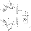
- Fig. 4 shows a further schematic diagram of a hydraulic circuit diagram for a control and / or regulating system according to a further exemplary embodiment.
- the structure of the hydraulic circuit diagram is analogous to Fig. 3 .
- a proportional valve 22 is provided instead of the adjustable throttle 21.
- the proportional valve 22 is arranged in each case between the accumulator 20 and the multi-way valve 19 in the hydraulic line 11.
- the proportional valve 22 can be controlled by the data processing unit.
- the spring and damper rate for damping yaw vibrations on the distributor linkage can be set depending on the different driving conditions of the agricultural utility vehicle.
- Fig. 5 shows a further schematic basic illustration of a hydraulic circuit diagram for a control and / or regulating system for an agricultural utility vehicle according to a further exemplary embodiment.
- the utility vehicle not shown, comprises a distributor linkage 12 for applying material such as fertilizers, pesticides or seeds according to FIG Fig. 1 .
- the two hydraulic cylinders 10 a, b can be acted upon with pressure to adjust the damping of yaw vibrations occurring on the distributor rod 12 in the direction of travel.
- the hydraulic cylinders 10 a, b are for this purpose with the distributor linkage according to Fig. 1 connected as described above.
- the two hydraulic cylinders 10 a, b are connected by means of a common hydraulic line 11.
- the hydraulic cylinders 10 a, b are each assigned a spring 23.
- the springs 23 can be designed, for example, as rubber buffers or by means of a memory which can act as a hydraulic spring.
- An adjustable throttle 21 is arranged in the hydraulic line 11.
- the throttle 21 can be controlled by the data processing unit by means of an actuating signal. A cross-sectional narrowing of the throttle 21 can be varied via the actuating signal in such a way that the volume flow of the hydraulic fluid in the hydraulic line 11 is adjusted.
- the damping of yaw vibrations occurring on the distributor linkage can thus be set differently depending on the driving condition.
- Fig. 6 shows a further schematic basic illustration of a hydraulic circuit diagram for a control and / or regulating system for an agricultural utility vehicle according to a further exemplary embodiment.
- the structure of the hydraulic circuit diagram is analogous to Fig. 5 .
- two throttles 21 connected in parallel are arranged.
- a proportional valve 22 is also assigned to a throttle 21.
- the combination of two throttles 21 and a proportional valve 22 can be used to switch between two different attenuations.
- the throttles 21 and the proportional valve 22 can be controlled by the data processing unit. This is particularly advantageous in order to set different damping depending on the driving state, such as cornering or straight-ahead driving of the commercial vehicle.
- several valve and throttle combinations connected in parallel are conceivable for realizing further different attenuations.
- Fig. 7 shows a further schematic basic illustration of a hydraulic circuit diagram for a control and / or regulating system for an agricultural utility vehicle according to a further exemplary embodiment.
- the structure of the hydraulic circuit diagram is analogous to Fig. 5 .
- a proportional valve 22 is arranged.
- the proportional valve 22 can be controlled by the data processing unit for setting the damping of yaw vibrations that occur depending on the driving condition by means of an actuating signal.
- Fig. 8 shows a further schematic basic illustration of a hydraulic circuit diagram for a control and / or regulating system for an agricultural utility vehicle according to a further exemplary embodiment.
- the structure of the hydraulic circuit diagram is analogous to Fig. 5 .
- two proportional valves 22 connected in parallel are arranged.
- a check valve 24 is assigned to each proportional valve 22.
- the respective proportional valve 22 can be controlled by the data processing unit for setting the damping of yaw vibrations that occur, depending on the driving condition, by means of an actuating signal.
- the proportional valves 22 and the associated check valves 24 are in this way in the hydraulic line 11 arranged that a direction-dependent damping control can be implemented.
- the damping of the distributor rod 12 can be adjusted when the distributor rod 12 oscillates on the right or left.
- Fig. 9 shows a further schematic basic illustration of a hydraulic circuit diagram for a control and / or regulating system for an agricultural utility vehicle according to a further exemplary embodiment.
- the structure of the hydraulic circuit diagram is analogous to Fig. 8 .
- a multi-way valve 19 is assigned to the hydraulic cylinders 10 a, b arranged centrally in the hydraulic line 11.
- the multi-way valve 19 is designed, for example, as a 4/3-way valve.
- the supply of hydraulic fluid for the hydraulic cylinders 10 a, b can be controlled centrally by means of the multi-way valve 19.
- the multi-way valve 19 can be controlled by the data processing unit.
- the multi-way valve is also connected to a hydraulic reservoir, which comprises a pump 16, a tank 15 and a pressure limiting valve 17.
- a direction-dependent damping of yaw vibrations occurring on the distributor linkage 12 can be implemented depending on the driving condition.
- Fig. 10 shows a further schematic basic illustration of a hydraulic circuit diagram for a control and / or regulating system for an agricultural utility vehicle according to a further exemplary embodiment.
- the structure of the hydraulic circuit diagram is analogous to Fig. 5 .
- a multi-way valve 19 is arranged in the hydraulic line 11.
- the multi-way valve 19 is designed, for example, as a 4/3-way valve.
- the supply of hydraulic fluid for the hydraulic cylinders 10 a, b can be controlled centrally by means of the multi-way valve 19.
- the multi-way valve 19 can be controlled by the data processing unit.
- the multi-way valve is also connected to a hydraulic reservoir, which comprises a pump 16, a tank 15 and a pressure limiting valve 17.
- the hydraulic cylinders 10 a, b can be actively controlled and moved in order to dampen yaw vibrations occurring on the distributor linkage 12.
- damping elements such as, for example, stroke-dependent dampers or variable dampers with bypass bores
- damping elements can generally be arranged for all exemplary embodiments.
- any valve or damping elements and their combinations are possible, whereby the damping of yaw vibrations occurring on the distributor linkage can be adjusted depending on the driving condition.
Landscapes
- Life Sciences & Earth Sciences (AREA)
- Engineering & Computer Science (AREA)
- Insects & Arthropods (AREA)
- Pest Control & Pesticides (AREA)
- Wood Science & Technology (AREA)
- Zoology (AREA)
- Environmental Sciences (AREA)
- Vehicle Body Suspensions (AREA)
Claims (15)
- Système de commande et/ou de régulation pour un véhicule utilitaire agricole qui comprend une rampe de distribution (12) pour épandre des matières telles que des engrais, des agents phytosanitaires ou des semences, qui s'étend transversalement à la direction de conduite et qui présente une partie centrale (2) et deux bras latéraux (3) connectés à la partie centrale (2) par des articulations, avec plusieurs portions de rampe (4) connectées par des articulations, pouvant être rabattues les unes sur les autres dans une position de transport et pouvant être dépliées dans une position de travail, au moins un dispositif de réglage étant associé à la rampe de distribution (12), de sorte que la rampe de distribution (12) soit disposée de manière à pouvoir pivoter autour d'un axe vertical, et au moins un capteur étant associé au véhicule utilitaire et le système présentant une unité de traitement de données qui est configurée de manière à ce que les signaux du capteur soient traités et qu'un signal de réglage pour le dispositif de réglage soit généré sur la base de ces signaux,
caractérisé en ce que
l'unité de traitement de données est configurée de telle sorte qu'en fonction de l'état de conduite différent du véhicule utilitaire agricole, un amortissement différent des oscillations de lacet autour de l'axe vertical se produisant au niveau de la rampe de distribution (12) puisse être ajusté, l'ajustement d'un amortissement différent s'effectuant en fonction de l'état de conduite par le biais de l'ajustement d'un paramètre de réglage différent. - Système selon la revendication 1,
caractérisé en ce que
l'unité de traitement de données est configurée de telle sorte qu'un amortissement des oscillations de lacet autour de l'axe vertical se produisant au niveau de la rampe de distribution (12) puisse être ajusté en fonction d'au moins un état de conduite du véhicule utilitaire agricole. - Système selon l'une quelconque des revendications précédentes,
caractérisé en ce que
l'au moins un état de conduite inclut une conduite en ligne droite et/ou une conduite en virage du véhicule utilitaire agricole, en particulier dans le cas d'une conduite en virage, en particulier dans le cas d'un changement du rayon de courbure, un amortissement différent, en particulier plus important que dans le cas d'un autre état de conduite, en particulier une conduite en ligne droite, pouvant être ajusté. - Système selon l'une quelconque des revendications précédentes,
caractérisé en ce que
l'amortissement peut être ajusté selon le principe d'un régulateur à deux points pour influencer la caractéristique d'amortissement, une valeur d'amortissement discrète étant à chaque fois prédéfinie pour deux états de conduite différents du véhicule utilitaire agricole. - Système selon l'une quelconque des revendications 1 à 3,
caractérisé en ce que
l'amortissement peut être ajusté selon le principe d'une régulation Skyhook pour influencer la caractéristique d'amortissement, en particulier l'amortissement pouvant être ajusté en fonction de l'état de conduite selon le principe d'une régulation Skyhook pour influencer la caractéristique d'amortissement. - Système selon la revendication 5,
caractérisé en ce
qu'une force d'amortissement nécessaire pour l'amortissement d'oscillations de lacet autour de l'axe vertical se produisant au niveau de la rampe de distribution (12) peut être déterminée par une force d'amortissement Skyhook, un paramètre Skyhook pouvant être ajusté au moyen d'une valeur constante ; ou
une force d'amortissement nécessaire pour l'amortissement d'oscillations de lacet autour de l'axe vertical se produisant au niveau de la rampe de distribution (12) peut être déterminée par une force d'amortissement Skyhook, un paramètre Skyhook pouvant être ajusté au moyen d'un régulateur à deux points à une valeur minimale ou maximale ; ou
une force d'amortissement nécessaire pour l'amortissement des oscillations de lacet autour de l'axe vertical se produisant au niveau de la rampe de distribution (12) peut être déterminée par une force d'amortissement Skyhook, un paramètre Skyhook pouvant être ajusté de manière continue. - Système selon l'une quelconque des revendications précédentes,
caractérisé en ce que
l'état de conduite peut être détecté au moyen de l'au moins un capteur, le capteur étant réalisé pour détecter une vitesse de rotation de la rampe de distribution (12) et/ou du véhicule utilitaire autour de l'axe vertical et/ou pour détecter une déviation de la rampe de distribution (12) et/ou pour détecter un angle de direction du véhicule utilitaire et étant associé au véhicule utilitaire agricole. - Système selon l'une quelconque des revendications précédentes,
caractérisé en ce que
sur la base des données de mesure des capteurs, dans le cas d'un dépassement d'une valeur limite, l'amortissement peut être ajusté en fonction de l'état de conduite. - Système selon l'une quelconque des revendications précédentes,
caractérisé en ce que
le dispositif de réglage comprend au moins un cylindre hydraulique (10a,b), une conduite hydraulique (11) qui est raccordée au cylindre hydraulique (10a,b) pour l'alimentation en liquide hydraulique, et au moins une unité de soupape hydraulique et/ou d'autres dispositifs d'amortissement, l'unité de soupape pouvant être à chaque fois ajustée par le biais d'un signal de réglage de l'unité de traitement de données ;
en particulier dans lequel :
l'unité de soupape hydraulique contient au moins une soupape dans le groupe des soupapes à plusieurs voies (19) et/ou des soupapes de régulation de la pression (18) et/ou des soupapes proportionnelles (22) et/ou des papillons d'étranglement (21) et/ou des diaphragmes pour la régulation de la pression hydraulique et/ou pour l'adaptation de l'amortissement ; et/ou les dispositifs d'amortissement supplémentaires comprennent un accumulateur (20) et un diaphragme réglable et/ou un accumulateur (20) et une soupape proportionnelle (22) et/ou au moins un papillon d'étranglement réglable (21) et/ou au moins deux soupapes proportionnelles (22) et/ou un amortisseur de réglage et/ou des ressorts pour l'adaptation du taux d'amortissement. - Véhicule utilitaire agricole pour épandre des matières telles que des engrais, des agents phytosanitaires ou des semences, comprenant un système de commande et/ou de régulation selon l'une quelconque des revendications précédentes.
- Procédé de commande et/ou de régulation d'un véhicule utilitaire agricole qui comprend un système de commande et/ou de régulation et une rampe de distribution (12) pour épandre des matières telles que des engrais, des agents phytosanitaires ou des semences, qui s'étend transversalement à la direction de conduite et qui présente une partie centrale (2) et deux bras latéraux (3) connectés à la partie centrale (2) par des articulations, avec plusieurs portions de rampe (4) connectées par des articulations, pouvant être rabattues les unes sur les autres dans une position de transport et pouvant être dépliées dans une position de travail, au moins un dispositif de réglage étant associé à la rampe de distribution (12), de sorte que la rampe de distribution (12) soit disposée de manière à pouvoir pivoter autour d'un axe vertical, et au moins un capteur étant associé au véhicule utilitaire et le système présentant une unité de traitement de données qui est configurée de manière à ce que les signaux du capteur soient traités et qu'un signal de réglage pour le dispositif de réglage soit généré sur la base de ces signaux,
caractérisé en ce
qu'en fonction de l'état de conduite différent du véhicule utilitaire agricole, un amortissement différent des oscillations de lacet autour de l'axe vertical se produisant au niveau de la rampe de distribution (12) est ajusté, l'ajustement d'un amortissement différent s'effectuant en fonction de l'état de conduite par le biais de l'ajustement d'un paramètre de réglage différent. - Procédé selon la revendication 11,
caractérisé en ce
qu'un amortissement d'oscillations de lacet autour de l'axe vertical se produisant au niveau de la rampe de distribution (12) est ajusté en fonction d'au moins un état de conduite, en particulier d'une conduite en ligne droite ou d'une conduite en virage, du véhicule utilitaire agricole ; en particulier dans le cas d'une conduite en virage, en particulier dans le cas d'un changement du rayon de courbure, un amortissement différent, en particulier plus important que dans le cas d'un autre état de conduite, en particulier une conduite en ligne droite, étant ajusté. - Procédé selon l'une quelconque des revendications 11 et 12,
caractérisé en ce que
l'amortissement est ajusté selon le principe d'un régulateur à deux points pour influencer la caractéristique d'amortissement, une valeur d'amortissement discrète étant à chaque fois prédéfinie pour deux états de conduite différents du véhicule utilitaire agricole. - Procédé selon l'une quelconque des revendications 11 à 13,
caractérisé en ce que
l'amortissement est ajusté selon le principe d'une régulation Skyhook pour influencer la caractéristique d'amortissement ; en particulier l'amortissement est ajusté en fonction de l'état de conduite selon le principe de la régulation Skyhook pour influencer la caractéristique d'amortissement ;
en particulier dans lequel
une force d'amortissement nécessaire pour l'amortissement d'oscillations de lacet autour de l'axe vertical se produisant au niveau de la rampe de distribution (12) est déterminée par une force d'amortissement Skyhook, un paramètre Skyhook étant ajusté au moyen d'une valeur constante ; ou
une force d'amortissement nécessaire pour l'amortissement d'oscillations de lacet autour de l'axe vertical se produisant au niveau de la rampe de distribution (12) est déterminée par une force d'amortissement Skyhook, un paramètre Skyhook étant ajusté au moyen d'un régulateur à deux points à une valeur minimale ou maximale ; ou
une force d'amortissement nécessaire pour l'amortissement des oscillations de lacet autour de l'axe vertical se produisant au niveau de la rampe de distribution (12) est déterminée par une force d'amortissement Skyhook, un paramètre Skyhook étant ajusté de manière continue. - Procédé selon l'une quelconque des revendications 11 à 14,
caractérisé en ce que sur la base des données de mesure des capteurs, dans le cas d'un dépassement d'une valeur limite, l'amortissement est ajusté en fonction de l'état de conduite.
Priority Applications (1)
| Application Number | Priority Date | Filing Date | Title |
|---|---|---|---|
| PL18187795T PL3440932T3 (pl) | 2017-08-11 | 2018-08-07 | Aktywne tłumienie drgań |
Applications Claiming Priority (1)
| Application Number | Priority Date | Filing Date | Title |
|---|---|---|---|
| DE102017118302.7A DE102017118302A1 (de) | 2017-08-11 | 2017-08-11 | Steuer- und/oder Regelsystem, landwirtschaftliches Nutzfahrzeug und Verfahren zur Steuerung und/oder Regelung eines landwirtschaftlichen Nutzfahrzeuges |
Publications (2)
| Publication Number | Publication Date |
|---|---|
| EP3440932A1 EP3440932A1 (fr) | 2019-02-13 |
| EP3440932B1 true EP3440932B1 (fr) | 2021-03-03 |
Family
ID=63173982
Family Applications (1)
| Application Number | Title | Priority Date | Filing Date |
|---|---|---|---|
| EP18187795.2A Active EP3440932B1 (fr) | 2017-08-11 | 2018-08-07 | Réglage active des vibrations |
Country Status (4)
| Country | Link |
|---|---|
| EP (1) | EP3440932B1 (fr) |
| DE (1) | DE102017118302A1 (fr) |
| DK (1) | DK3440932T3 (fr) |
| PL (1) | PL3440932T3 (fr) |
Cited By (1)
| Publication number | Priority date | Publication date | Assignee | Title |
|---|---|---|---|---|
| EP4321021A1 (fr) * | 2022-08-10 | 2024-02-14 | Amazonen-Werke H. Dreyer SE & Co. KG | Système de commande et/ou de régulation, véhicule utilitaire agricole |
Families Citing this family (3)
| Publication number | Priority date | Publication date | Assignee | Title |
|---|---|---|---|---|
| DE102018201121B4 (de) * | 2018-01-24 | 2022-07-28 | Amazonen-Werke H. Dreyer SE & Co. KG | Regelvorrichtung für ein landwirtschaftliches Nutzfahrzeug und Verfahren zum Betreiben des Nutzfahrzeugs |
| DE102019114084A1 (de) * | 2019-05-27 | 2020-12-03 | Amazonen-Werke H. Dreyer Gmbh & Co. Kg | Landwirtschaftliches Gerät mit verbesserter Neigungsregelung |
| DE102023121074A1 (de) * | 2023-08-08 | 2025-02-13 | Voith Patent Gmbh | Hydraulisches Steuerungssystem für ein Spritzgestänge an einer landwirtschaftlichen Feldspritze |
Family Cites Families (7)
| Publication number | Priority date | Publication date | Assignee | Title |
|---|---|---|---|---|
| DE102005019238A1 (de) * | 2005-04-26 | 2006-11-09 | Amazonen-Werke H. Dreyer Gmbh & Co. Kg | Landwirtschaftliche Verteilmaschine |
| EP2837285B1 (fr) | 2013-08-09 | 2021-07-07 | Lemken GmbH & Co. KG | Rampe de pulvérisation d'un pulvérisateur agricole |
| WO2015040133A1 (fr) * | 2013-09-18 | 2015-03-26 | Horsch Leeb Application Systems Gmbh | Dispositif de distribution de substances actives liquides et/ou solides et procédé de commande d'un tel dispositif |
| EP4018801A1 (fr) * | 2013-11-10 | 2022-06-29 | HORSCH LEEB Application Systems GmbH | Dispositif d'extraction de liquides et/ou d'agents actifs solides et procédé de commande d'un tel dispositif |
| DE102014111090A1 (de) * | 2014-08-05 | 2016-02-11 | Amazonen-Werke H. Dreyer Gmbh & Co. Kg | Vorrichtung und Verfahren zur Bewegungssteuerung eines Verteilergestänges einer landwirtschaftlichen Verteilmaschine |
| DE102015102975A1 (de) * | 2015-03-02 | 2016-09-08 | Horsch Leeb Application Systems Gmbh | Vorrichtung zum Ausbringen von flüssigen und/oder festen Wirkstoffen und Verfahren zur Steuerung einer solchen Vorrichtung |
| DE102015113721A1 (de) * | 2015-08-19 | 2017-02-23 | Amazonen-Werke H. Dreyer Gmbh & Co. Kg | Aufhängung für eine landwirtschaftliche Maschine, landwirtschaftliche Maschine mit einer solchen Aufhängung und Verfahren zum Betreiben einer landwirtschaftlichen Maschine |
-
2017
- 2017-08-11 DE DE102017118302.7A patent/DE102017118302A1/de not_active Withdrawn
-
2018
- 2018-08-07 PL PL18187795T patent/PL3440932T3/pl unknown
- 2018-08-07 DK DK18187795.2T patent/DK3440932T3/da active
- 2018-08-07 EP EP18187795.2A patent/EP3440932B1/fr active Active
Non-Patent Citations (1)
| Title |
|---|
| None * |
Cited By (1)
| Publication number | Priority date | Publication date | Assignee | Title |
|---|---|---|---|---|
| EP4321021A1 (fr) * | 2022-08-10 | 2024-02-14 | Amazonen-Werke H. Dreyer SE & Co. KG | Système de commande et/ou de régulation, véhicule utilitaire agricole |
Also Published As
| Publication number | Publication date |
|---|---|
| PL3440932T3 (pl) | 2021-10-11 |
| DK3440932T3 (da) | 2021-06-07 |
| EP3440932A1 (fr) | 2019-02-13 |
| DE102017118302A1 (de) | 2019-02-14 |
Similar Documents
| Publication | Publication Date | Title |
|---|---|---|
| EP2829177B1 (fr) | Épandeuse agricole équipée d'un dispositif d'épandage et système de commande du dispositif d'épandage | |
| EP3357333B1 (fr) | Machine d'épandage agricole à commande automatique d'amortissement de la r ampe d'épandage | |
| EP3629725B1 (fr) | Dispositif de commande pour un système d'épandage et système d'épandage équipé d'un tel dispositif de commande | |
| EP3440932B1 (fr) | Réglage active des vibrations | |
| EP3337317B1 (fr) | Suspension d'une rampe de pulvérisation pour une machine agricole | |
| EP3753407B1 (fr) | Appareil agricole à réglage de l'inclinaison amélioré | |
| EP2064948A2 (fr) | Rampe de pulvérisation | |
| EP3592143B1 (fr) | Système de commande et/ou de régulation d'un véhicule utilitaire agricole et procédé de commande et/ou de régulation d'un véhicule utilitaire agricole | |
| DE102004012945A1 (de) | Vorrichtung und Verfahren zur Bewegungstilgung bei Baumaschinen | |
| EP2526755B1 (fr) | Machine de répartition agricole | |
| DE102020118528A1 (de) | Landwirtschaftliche Verteilmaschine, vorzugsweise eine Feldspritze oder ein Düngerstreuer | |
| EP4212018A1 (fr) | Appareil agricole avec réglage d'inclinaison amélioré | |
| EP3141114B1 (fr) | Systeme d'epandage et procede d'epandage | |
| EP3804516A1 (fr) | Machine d'épandage agricole, de préférence pulvérisateur ou distributeur d'engrais | |
| EP3975712B1 (fr) | Système de commande et/ou de régulation destiné à un appareil agricole | |
| EP3975711B1 (fr) | Système de commande et/ou de régulation pour une machine agricole | |
| EP3305071A1 (fr) | Système de commande, véhicule agricole et procédé de commande d'un véhicule agricole | |
| DE102018103862A1 (de) | Aufhängung für eine landwirtschaftliche Maschine und Verfahren zum Betreiben einer landwirtschaftlichen Maschine | |
| EP2526756B1 (fr) | Machine de répartition agricole avec barre de distribution | |
| EP3804515A1 (fr) | Machine d'épandage agricole, de préférence pulvérisateur agricole ou épandeur pneumatique d'engrais | |
| EP4321021A1 (fr) | Système de commande et/ou de régulation, véhicule utilitaire agricole | |
| DE102017104804A1 (de) | Steuer- und/oder Regelsystem, landwirtschaftliches Nutzfahrzeug und Verfahren zur Steuerung und/oder Regelung eines landwirtschaftlichen Nutzfahrzeuges | |
| EP3482631A1 (fr) | Système de commande et / ou de régulation pour véhicule utilitaire agricole, véhicule utilitaire agricole et procédé de commande et / ou de régulation correspondant | |
| DE202022002936U1 (de) | Landwirtschaftliches Gerät mit verbesserter Neigungsregelung |
Legal Events
| Date | Code | Title | Description |
|---|---|---|---|
| PUAI | Public reference made under article 153(3) epc to a published international application that has entered the european phase |
Free format text: ORIGINAL CODE: 0009012 |
|
| STAA | Information on the status of an ep patent application or granted ep patent |
Free format text: STATUS: THE APPLICATION HAS BEEN PUBLISHED |
|
| AK | Designated contracting states |
Kind code of ref document: A1 Designated state(s): AL AT BE BG CH CY CZ DE DK EE ES FI FR GB GR HR HU IE IS IT LI LT LU LV MC MK MT NL NO PL PT RO RS SE SI SK SM TR |
|
| AX | Request for extension of the european patent |
Extension state: BA ME |
|
| STAA | Information on the status of an ep patent application or granted ep patent |
Free format text: STATUS: REQUEST FOR EXAMINATION WAS MADE |
|
| 17P | Request for examination filed |
Effective date: 20190222 |
|
| RBV | Designated contracting states (corrected) |
Designated state(s): AL AT BE BG CH CY CZ DE DK EE ES FI FR GB GR HR HU IE IS IT LI LT LU LV MC MK MT NL NO PL PT RO RS SE SI SK SM TR |
|
| GRAP | Despatch of communication of intention to grant a patent |
Free format text: ORIGINAL CODE: EPIDOSNIGR1 |
|
| STAA | Information on the status of an ep patent application or granted ep patent |
Free format text: STATUS: GRANT OF PATENT IS INTENDED |
|
| INTG | Intention to grant announced |
Effective date: 20201120 |
|
| GRAS | Grant fee paid |
Free format text: ORIGINAL CODE: EPIDOSNIGR3 |
|
| GRAA | (expected) grant |
Free format text: ORIGINAL CODE: 0009210 |
|
| STAA | Information on the status of an ep patent application or granted ep patent |
Free format text: STATUS: THE PATENT HAS BEEN GRANTED |
|
| AK | Designated contracting states |
Kind code of ref document: B1 Designated state(s): AL AT BE BG CH CY CZ DE DK EE ES FI FR GB GR HR HU IE IS IT LI LT LU LV MC MK MT NL NO PL PT RO RS SE SI SK SM TR |
|
| REG | Reference to a national code |
Ref country code: GB Ref legal event code: FG4D Free format text: NOT ENGLISH |
|
| REG | Reference to a national code |
Ref country code: AT Ref legal event code: REF Ref document number: 1366188 Country of ref document: AT Kind code of ref document: T Effective date: 20210315 Ref country code: CH Ref legal event code: EP |
|
| REG | Reference to a national code |
Ref country code: DE Ref legal event code: R096 Ref document number: 502018004108 Country of ref document: DE |
|
| REG | Reference to a national code |
Ref country code: IE Ref legal event code: FG4D Free format text: LANGUAGE OF EP DOCUMENT: GERMAN |
|
| RAP4 | Party data changed (patent owner data changed or rights of a patent transferred) |
Owner name: AMAZONEN-WERK H. DREYER SE & CO. KG |
|
| REG | Reference to a national code |
Ref country code: DE Ref legal event code: R081 Ref document number: 502018004108 Country of ref document: DE Owner name: AMAZONEN-WERKE H. DREYER SE & CO. KG, DE Free format text: FORMER OWNER: AMAZONEN-WERKE H.DREYER GMBH &CO.KG, 49205 HASBERGEN, DE |
|
| RAP4 | Party data changed (patent owner data changed or rights of a patent transferred) |
Owner name: AMAZONEN-WERKE H. DREYER SE & CO. KG |
|
| REG | Reference to a national code |
Ref country code: DK Ref legal event code: T3 Effective date: 20210603 |
|
| REG | Reference to a national code |
Ref country code: NL Ref legal event code: FP |
|
| REG | Reference to a national code |
Ref country code: LT Ref legal event code: MG9D |
|
| PG25 | Lapsed in a contracting state [announced via postgrant information from national office to epo] |
Ref country code: NO Free format text: LAPSE BECAUSE OF FAILURE TO SUBMIT A TRANSLATION OF THE DESCRIPTION OR TO PAY THE FEE WITHIN THE PRESCRIBED TIME-LIMIT Effective date: 20210603 Ref country code: LT Free format text: LAPSE BECAUSE OF FAILURE TO SUBMIT A TRANSLATION OF THE DESCRIPTION OR TO PAY THE FEE WITHIN THE PRESCRIBED TIME-LIMIT Effective date: 20210303 Ref country code: BG Free format text: LAPSE BECAUSE OF FAILURE TO SUBMIT A TRANSLATION OF THE DESCRIPTION OR TO PAY THE FEE WITHIN THE PRESCRIBED TIME-LIMIT Effective date: 20210603 Ref country code: FI Free format text: LAPSE BECAUSE OF FAILURE TO SUBMIT A TRANSLATION OF THE DESCRIPTION OR TO PAY THE FEE WITHIN THE PRESCRIBED TIME-LIMIT Effective date: 20210303 Ref country code: GR Free format text: LAPSE BECAUSE OF FAILURE TO SUBMIT A TRANSLATION OF THE DESCRIPTION OR TO PAY THE FEE WITHIN THE PRESCRIBED TIME-LIMIT Effective date: 20210604 Ref country code: HR Free format text: LAPSE BECAUSE OF FAILURE TO SUBMIT A TRANSLATION OF THE DESCRIPTION OR TO PAY THE FEE WITHIN THE PRESCRIBED TIME-LIMIT Effective date: 20210303 |
|
| PG25 | Lapsed in a contracting state [announced via postgrant information from national office to epo] |
Ref country code: RS Free format text: LAPSE BECAUSE OF FAILURE TO SUBMIT A TRANSLATION OF THE DESCRIPTION OR TO PAY THE FEE WITHIN THE PRESCRIBED TIME-LIMIT Effective date: 20210303 Ref country code: LV Free format text: LAPSE BECAUSE OF FAILURE TO SUBMIT A TRANSLATION OF THE DESCRIPTION OR TO PAY THE FEE WITHIN THE PRESCRIBED TIME-LIMIT Effective date: 20210303 Ref country code: SE Free format text: LAPSE BECAUSE OF FAILURE TO SUBMIT A TRANSLATION OF THE DESCRIPTION OR TO PAY THE FEE WITHIN THE PRESCRIBED TIME-LIMIT Effective date: 20210303 |
|
| PG25 | Lapsed in a contracting state [announced via postgrant information from national office to epo] |
Ref country code: EE Free format text: LAPSE BECAUSE OF FAILURE TO SUBMIT A TRANSLATION OF THE DESCRIPTION OR TO PAY THE FEE WITHIN THE PRESCRIBED TIME-LIMIT Effective date: 20210303 Ref country code: CZ Free format text: LAPSE BECAUSE OF FAILURE TO SUBMIT A TRANSLATION OF THE DESCRIPTION OR TO PAY THE FEE WITHIN THE PRESCRIBED TIME-LIMIT Effective date: 20210303 Ref country code: SM Free format text: LAPSE BECAUSE OF FAILURE TO SUBMIT A TRANSLATION OF THE DESCRIPTION OR TO PAY THE FEE WITHIN THE PRESCRIBED TIME-LIMIT Effective date: 20210303 |
|
| PG25 | Lapsed in a contracting state [announced via postgrant information from national office to epo] |
Ref country code: PT Free format text: LAPSE BECAUSE OF FAILURE TO SUBMIT A TRANSLATION OF THE DESCRIPTION OR TO PAY THE FEE WITHIN THE PRESCRIBED TIME-LIMIT Effective date: 20210705 Ref country code: SK Free format text: LAPSE BECAUSE OF FAILURE TO SUBMIT A TRANSLATION OF THE DESCRIPTION OR TO PAY THE FEE WITHIN THE PRESCRIBED TIME-LIMIT Effective date: 20210303 Ref country code: RO Free format text: LAPSE BECAUSE OF FAILURE TO SUBMIT A TRANSLATION OF THE DESCRIPTION OR TO PAY THE FEE WITHIN THE PRESCRIBED TIME-LIMIT Effective date: 20210303 Ref country code: IS Free format text: LAPSE BECAUSE OF FAILURE TO SUBMIT A TRANSLATION OF THE DESCRIPTION OR TO PAY THE FEE WITHIN THE PRESCRIBED TIME-LIMIT Effective date: 20210703 |
|
| REG | Reference to a national code |
Ref country code: DE Ref legal event code: R097 Ref document number: 502018004108 Country of ref document: DE |
|
| PLBE | No opposition filed within time limit |
Free format text: ORIGINAL CODE: 0009261 |
|
| STAA | Information on the status of an ep patent application or granted ep patent |
Free format text: STATUS: NO OPPOSITION FILED WITHIN TIME LIMIT |
|
| PG25 | Lapsed in a contracting state [announced via postgrant information from national office to epo] |
Ref country code: ES Free format text: LAPSE BECAUSE OF FAILURE TO SUBMIT A TRANSLATION OF THE DESCRIPTION OR TO PAY THE FEE WITHIN THE PRESCRIBED TIME-LIMIT Effective date: 20210303 Ref country code: AL Free format text: LAPSE BECAUSE OF FAILURE TO SUBMIT A TRANSLATION OF THE DESCRIPTION OR TO PAY THE FEE WITHIN THE PRESCRIBED TIME-LIMIT Effective date: 20210303 |
|
| 26N | No opposition filed |
Effective date: 20211206 |
|
| PG25 | Lapsed in a contracting state [announced via postgrant information from national office to epo] |
Ref country code: SI Free format text: LAPSE BECAUSE OF FAILURE TO SUBMIT A TRANSLATION OF THE DESCRIPTION OR TO PAY THE FEE WITHIN THE PRESCRIBED TIME-LIMIT Effective date: 20210303 |
|
| REG | Reference to a national code |
Ref country code: CH Ref legal event code: PL |
|
| PG25 | Lapsed in a contracting state [announced via postgrant information from national office to epo] |
Ref country code: MC Free format text: LAPSE BECAUSE OF FAILURE TO SUBMIT A TRANSLATION OF THE DESCRIPTION OR TO PAY THE FEE WITHIN THE PRESCRIBED TIME-LIMIT Effective date: 20210303 |
|
| REG | Reference to a national code |
Ref country code: BE Ref legal event code: MM Effective date: 20210831 |
|
| PG25 | Lapsed in a contracting state [announced via postgrant information from national office to epo] |
Ref country code: LI Free format text: LAPSE BECAUSE OF NON-PAYMENT OF DUE FEES Effective date: 20210831 Ref country code: CH Free format text: LAPSE BECAUSE OF NON-PAYMENT OF DUE FEES Effective date: 20210831 |
|
| PG25 | Lapsed in a contracting state [announced via postgrant information from national office to epo] |
Ref country code: IS Free format text: LAPSE BECAUSE OF FAILURE TO SUBMIT A TRANSLATION OF THE DESCRIPTION OR TO PAY THE FEE WITHIN THE PRESCRIBED TIME-LIMIT Effective date: 20210703 Ref country code: LU Free format text: LAPSE BECAUSE OF NON-PAYMENT OF DUE FEES Effective date: 20210807 |
|
| PG25 | Lapsed in a contracting state [announced via postgrant information from national office to epo] |
Ref country code: IE Free format text: LAPSE BECAUSE OF NON-PAYMENT OF DUE FEES Effective date: 20210807 Ref country code: BE Free format text: LAPSE BECAUSE OF NON-PAYMENT OF DUE FEES Effective date: 20210831 |
|
| P01 | Opt-out of the competence of the unified patent court (upc) registered |
Effective date: 20230523 |
|
| PG25 | Lapsed in a contracting state [announced via postgrant information from national office to epo] |
Ref country code: CY Free format text: LAPSE BECAUSE OF FAILURE TO SUBMIT A TRANSLATION OF THE DESCRIPTION OR TO PAY THE FEE WITHIN THE PRESCRIBED TIME-LIMIT Effective date: 20210303 |
|
| PG25 | Lapsed in a contracting state [announced via postgrant information from national office to epo] |
Ref country code: HU Free format text: LAPSE BECAUSE OF FAILURE TO SUBMIT A TRANSLATION OF THE DESCRIPTION OR TO PAY THE FEE WITHIN THE PRESCRIBED TIME-LIMIT; INVALID AB INITIO Effective date: 20180807 |
|
| PG25 | Lapsed in a contracting state [announced via postgrant information from national office to epo] |
Ref country code: MK Free format text: LAPSE BECAUSE OF FAILURE TO SUBMIT A TRANSLATION OF THE DESCRIPTION OR TO PAY THE FEE WITHIN THE PRESCRIBED TIME-LIMIT Effective date: 20210303 |
|
| PG25 | Lapsed in a contracting state [announced via postgrant information from national office to epo] |
Ref country code: MT Free format text: LAPSE BECAUSE OF FAILURE TO SUBMIT A TRANSLATION OF THE DESCRIPTION OR TO PAY THE FEE WITHIN THE PRESCRIBED TIME-LIMIT Effective date: 20210303 |
|
| REG | Reference to a national code |
Ref country code: AT Ref legal event code: MM01 Ref document number: 1366188 Country of ref document: AT Kind code of ref document: T Effective date: 20230807 |
|
| PG25 | Lapsed in a contracting state [announced via postgrant information from national office to epo] |
Ref country code: AT Free format text: LAPSE BECAUSE OF NON-PAYMENT OF DUE FEES Effective date: 20230807 |
|
| PG25 | Lapsed in a contracting state [announced via postgrant information from national office to epo] |
Ref country code: AT Free format text: LAPSE BECAUSE OF NON-PAYMENT OF DUE FEES Effective date: 20230807 |
|
| PGFP | Annual fee paid to national office [announced via postgrant information from national office to epo] |
Ref country code: PL Payment date: 20250612 Year of fee payment: 8 |
|
| PGFP | Annual fee paid to national office [announced via postgrant information from national office to epo] |
Ref country code: GB Payment date: 20250619 Year of fee payment: 8 |
|
| PGFP | Annual fee paid to national office [announced via postgrant information from national office to epo] |
Ref country code: NL Payment date: 20250613 Year of fee payment: 8 |
|
| PGFP | Annual fee paid to national office [announced via postgrant information from national office to epo] |
Ref country code: FR Payment date: 20250610 Year of fee payment: 8 |
|
| PGFP | Annual fee paid to national office [announced via postgrant information from national office to epo] |
Ref country code: DK Payment date: 20250814 Year of fee payment: 8 Ref country code: DE Payment date: 20250611 Year of fee payment: 8 |
|
| PGFP | Annual fee paid to national office [announced via postgrant information from national office to epo] |
Ref country code: IT Payment date: 20250722 Year of fee payment: 8 |
|
| PG25 | Lapsed in a contracting state [announced via postgrant information from national office to epo] |
Ref country code: TR Free format text: LAPSE BECAUSE OF FAILURE TO SUBMIT A TRANSLATION OF THE DESCRIPTION OR TO PAY THE FEE WITHIN THE PRESCRIBED TIME-LIMIT Effective date: 20210303 |
|
| PGFP | Annual fee paid to national office [announced via postgrant information from national office to epo] |
Ref country code: AT Payment date: 20260410 Year of fee payment: 5 |